

Panasonic 2SD2420 Datasheet
Power Transistors
2SD2420
Silicon NPN triple diffusion planer type Darlington
For power amplification
■ Features
• High forward current transfer ratio hFE: 2 000 to 10 000
• Dielectric breakdown voltage of the package: > 5 kV
■ Absolute Maximum Ratings TC = 25°C
Parameter Symbol Rating Unit
Collector to base voltage V
Collector to emitter voltage V
Emitter to base voltage V
Peak collector current I
Collector current I
Collector power
dissipation
TC = 25°CPC40 W
Ta = 25°C 2.0
Junction temperature T
Storage temperature T
CBO
CEO
EBO
CP
C
j
stg
60 V
60 V
5V
8A
4 A
150 °C
−55 to +150 °C
±0.5
15.0
±0.2
4.2
±0.2
13.7
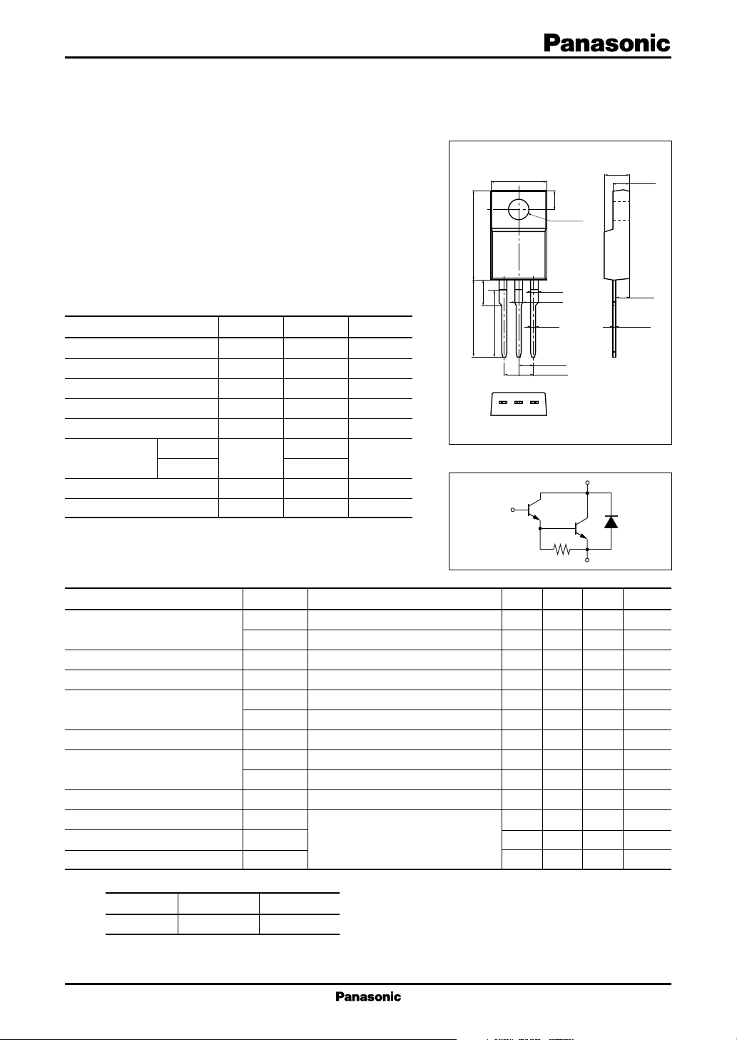
Internal Connection
9.9
Solder Dip
123
B
±0.3
0.8
2.54
5.08
±0.5
3.0
φ 3.2
±0.1
1.4
±0.2
1.6
±0.2
±0.1
±0.30
±0.50
Unit: mm
4.6
±0.2
2.9
±0.2
2.6
±0.1
0.55
±0.15
1: Base
2: Collector
3: Emitter
TO-220D Package
C
■ Electrical Characteristics TC = 25°C ± 3°C
Parameter Symbol Conditions Min Typ Max Unit
Collector cutoff current I
Emitter cutoff current I
Collector to emitter voltage V
Forward current transfer ratio h
Base to emitter voltage (DC value) V
Collector to emitter saturation voltage V
Transition frequency f
Turn-on time t
Storage time t
Fall time t
Note)*: Rank classification
Rank P Q
h
FE2
4 000 to 10 000 2 000 to 5 000
CBO
I
CEO
EBO
CEO
FE1
h
FE2
CE(sat)1IC
V
CE(sat)2IC
stg
VCB = 60 V, IE = 0 200 µA
VCE = 30 V, IB = 0 500 µA
VEB = 5 V, IC = 02mA
IC = 30 mA, IB = 060V
VCE = 3 V, IC = 0.5 A 1 000
*VCE = 3 V, IC = 3 A 2 000 10 000
VCE = 3 V, IC = 3 A 2.5 V
BE
= 3 A, IB = 12 mA 2.0 V
= 5 A, IB = 20 mA 4.0 V
VCE = 10 V, IC = 0.5 A, f = 1 MHz 20 MHz
T
IC = 3 A, IB1 = 12 mA, IB2 = −12 mA 0.5 µs
on
VCC = 50 V 4.0 µs
f
E
1.0 µs
1
 Loading...