

Panasonic 2SC5592 Datasheet
Transistors
2SC5592
Silicon NPN epitaxial planer type
For DC-DC converter
For various driver circuits
■ Features
• Low collector to emitter saturation voltage
capacitance
• High-speed switching
Mini type 3-pin package, allowing downsizing and thinning of the
•
equipment.
• Complementary pair with 2SA2010
V
CE(sat)
, large current
10°
0.40
3
1
(0.95) (0.95)
±0.1
1.9
+0.20
2.90
–0.05
Unit: mm
+0.10
–0.05
+0.25
–0.05
+0.2
–0.3
2.8
1.50
2
(0.65)
+0.2
–0.1
+0.3
–0.1
1.1
1.1
+0.10
0.16
–0.06
5°
0.4±0.2
■ Absolute Maximum Ratings Ta = 25°C
Parameter Symbol Rating Unit
Collector to base voltage V
Collector to emitter voltage V
Emitter to base voltage V
Peak collector current I
Collector current I
Collector power dissipation
*
Junction temperature T
Storage temperature T
CBO
CEO
EBO
CP
P
C
C
j
stg
15 V
15 V
5V
10 A
2.5 A
600 mW
150 °C
−55 to +150 °C
Note)*: Measure on the ceramic substrate at 15 × 15 × 0.6 mm3.
■ Electrical Characteristics Ta = 25°C ± 3°C
Parameter Symbol Conditions Min Typ Max Unit
Collector cutoff current I
Collector to base voltage V
Collector to emitter voltage V
Emitter to base voltage V
1
Forward current transfer ratio
Collector to emitter saturation voltage
*
1
*
Collector output capacitance C
Transition frequency f
2
Turn-on time
Storage time
Fall time
*
2
*
2
*
Note)*1: Rank classification (≤ 1 ms)
2: Refere to the measurement circuit.
*
V
CBO
CBO
CEO
EBO
h
FE1
h
FE2
CE(sat)
ob
T
t
on
t
stg
t
f
VCB = 10 V, IE = 0 0.1 µA
IC = 10 µA, IE = 0 15 V
IC = 1 mA, IB = 015V
IE = 10 µA, IC = 05 V
VCE = 2 V, IC = 100 mA 400 1 000
VCE = 2 V, IC = 2.5 A 280
IC = 1 A, IB = 10 mA 110 mV
IC = 2.5 A, IB = 50 mA 220 320 mV
VCB = 10 V, IE = 0, f = 1 MHz 30 pF
VCB = 10 V, IE = −50 mA 180 MHz
f = 200 MHz
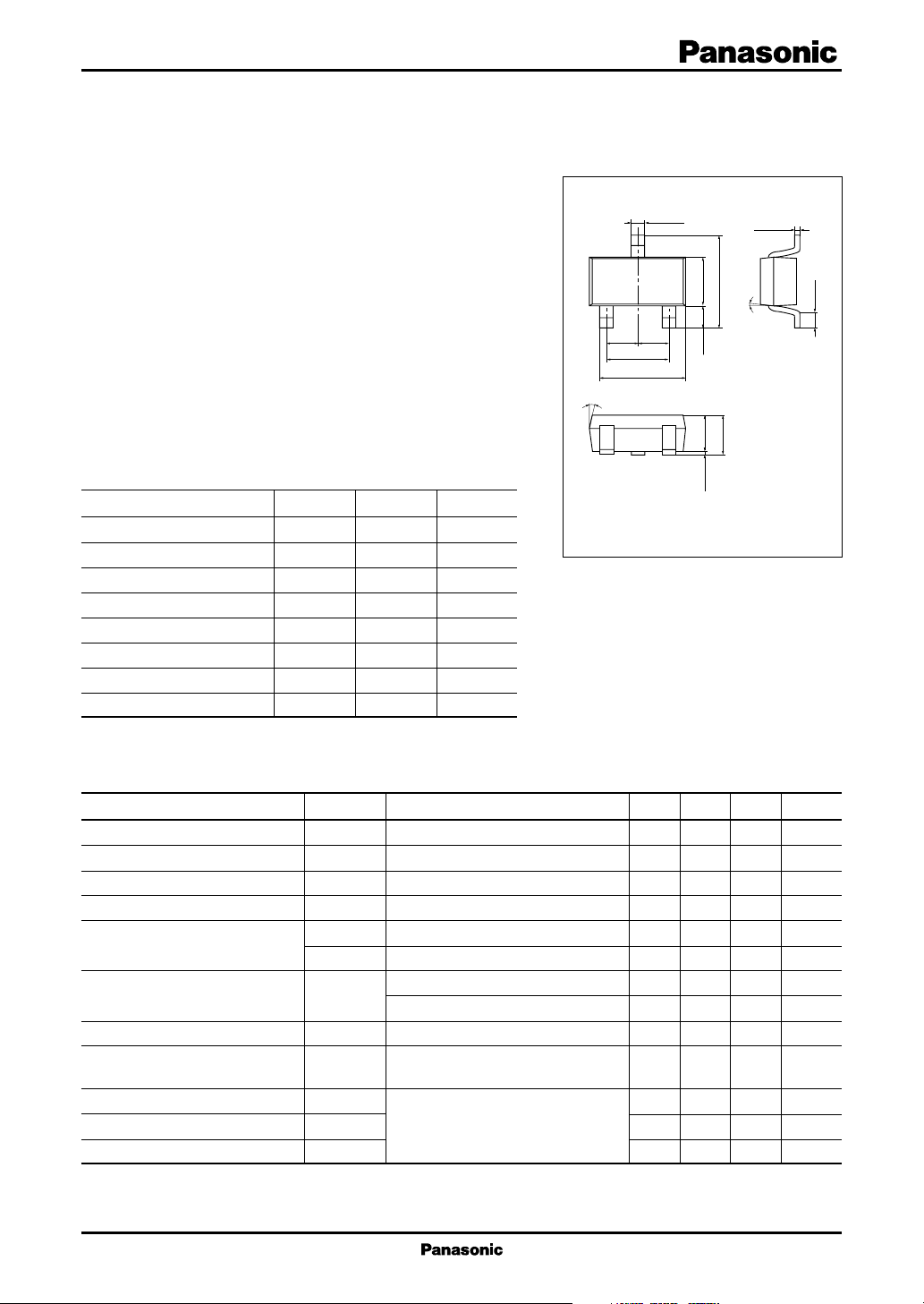
Mini Type Package (3-pin)
Marking Symbol: 2T
0 to 0.1
1: Base
2: Emitter
3: Collector
EIAJ: SC-59
30 ns
100 ns
10 ns
1

2SC5592 Transistors
■ Measurement Circuit
IB2
Input
PW = 20 µs
DC ≤ 1%
−201B1 = 201B2 = IC = 1.5 A
IB1
RB
470 µF
V
CC
Output
R
L
= 5 V
2
 Loading...