

Panasonic 2SC4953 Datasheet
Po wer Transistors
2SC4953
Silicon NPN triple diffusion planar type
For high breakdown voltage high-speed switching
Features
■
●
High-speed switching
●
High collector to base voltage V
●
Wide area of safe operation (ASO)
●
Satisfactory linearity of foward current transfer ratio h
●
Dielectric breakdown voltage of the package: > 5kV
Absolute Maximum Ratings (T
■
Parameter
Collector to base voltage
Collector to emitter voltage
Emitter to base voltage
Peak collector current
Collector current
Base current
Collector power
dissipation
Junction temperature
Storage temperature
TC=25°C
Ta=25°C
Symbol
V
CBO
V
CES
V
CEO
V
EBO
I
CP
I
C
I
B
P
C
T
j
T
stg
CBO
=25˚C)
C
Ratings
500
500
400
7
6
3
1.2
30
2.0
150
–55 to +150
FE
Unit
V
V
V
V
A
A
A
W
˚C
˚C
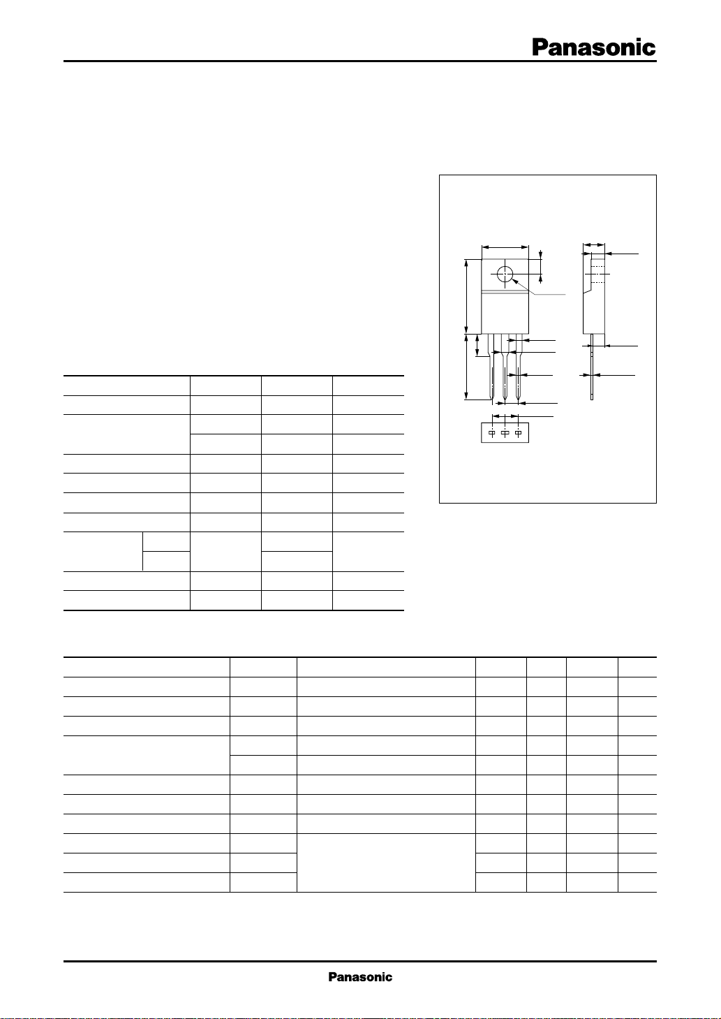
Unit: mm
9.9±0.3
φ3.2±0.1
15.0±0.513.7±0.2
1.4±0.2
1
1.6±0.2
0.8±0.1
2.54±0.3
23
5.08±0.5
TO–220D Full Pack Package
4.2±0.2
4.6±0.2
2.9±0.2
3.0±0.5
2.6±0.1
0.55±0.15
1:Base
2:Collector
3:Emitter
Electrical Characteristics (T
■
Parameter
Collector cutoff current
Emitter cutoff current
Collector to emitter voltage
Forward current transfer ratio
Collector to emitter saturation voltage
Base to emitter saturation voltage
Transition frequency
Turn-on time
Storage time
Fall time
Symbol
I
CBO
I
EBO
V
CEO
h
FE1
h
FE2
V
CE(sat)
V
BE(sat)
f
T
t
on
t
stg
t
f
=25˚C)
C
Conditions
VCB = 500V, IE = 0
VEB = 5V, IC = 0
IC = 10mA, IB = 0
VCE = 5V, IC = 0.1A
VCE = 2V, IC = 1.2A
IC = 1.5A, IB = 0.3A
IC = 1.5A, IB = 0.3A
VCE = 10V, IC = 0.2A, f = 1MHz
IC = 1.5A, IB1 = 0.15A, IB2 = – 0.3A,
VCC = 200V
min
400
10
8
typ10max
100
100
40
1.0
1.5
1.0
3.0
0.3
Unit
µA
µA
V
V
V
MHz
µs
µs
µs
1
Po wer Transistors 2SC4953
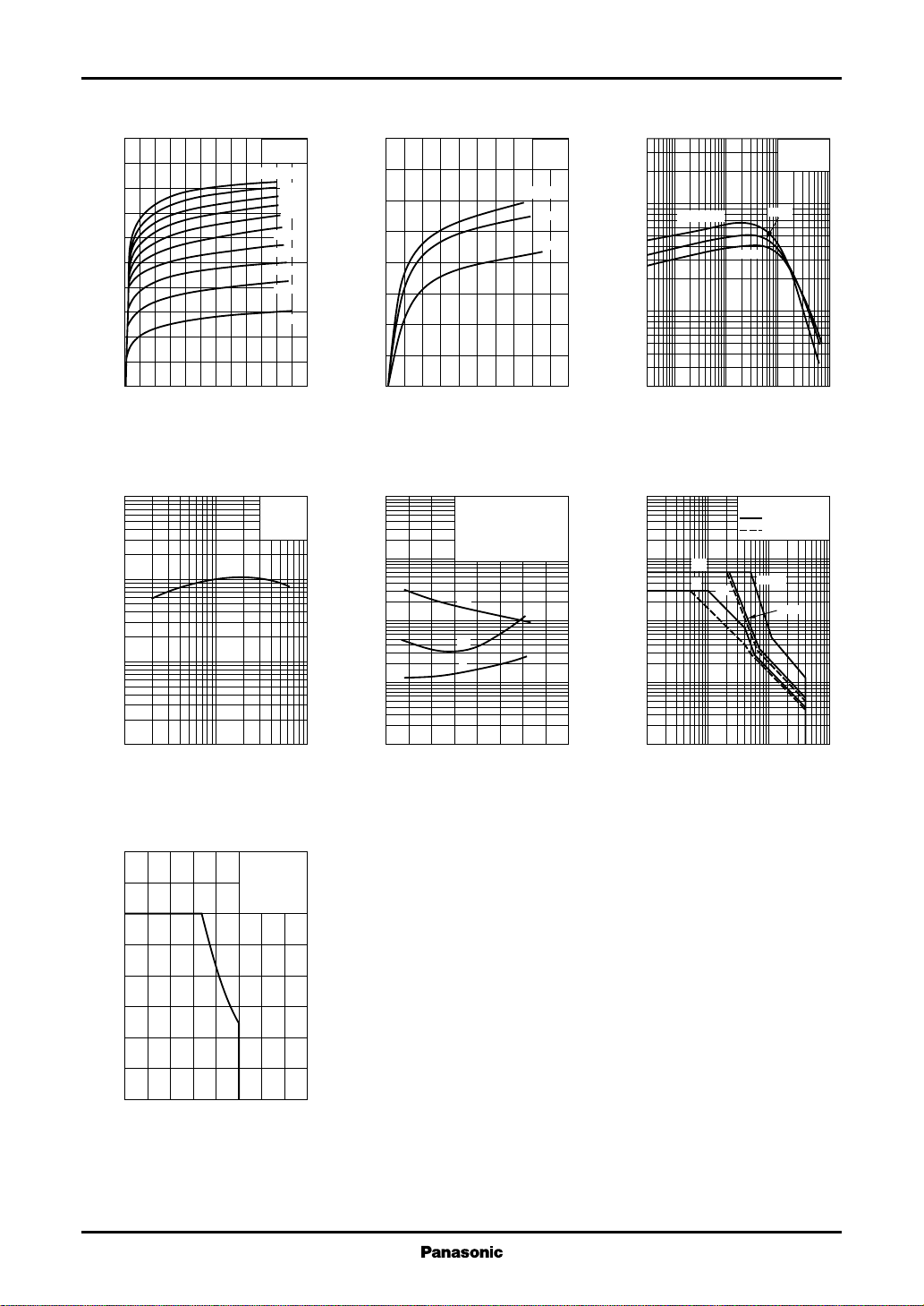
IC—V
CE
5.0
4.5
4.0
)
A
(
3.5
C
3.0
2.5
2.0
1.5
Collector current I
1.0
0.5
0
012108264
I
B
Collector to emitter voltage VCE (V
fT—I
C
100
)
30
MHz
(
T
10
3
1
0.3
Transition frequency f
0.1
0.01 0.03 0.1 0.3 1
VCE=10V
f=1MHz
T
Collector current IC (A
TC=25˚C
=500mA
450mA
400mA
350mA
300mA
250mA
200mA
150mA
100mA
50mA
=25˚C
C
)
IC—V
CE(sat)
8
7
)
6
A
(
C
5
4
3
2
Collector current I
1
0
0 2.52.00.5 1.51.0
)
Collector to emitter saturation voltage V
ton, t
, tf — I
stg
100
30
)
µs
(
10
f
,t
stg
3
,t
on
1
0.3
0.1
Pulsed tw=1ms
Duty cycle=1%
I
C/IB
V
CC
T
C
t
stg
t
on
t
f
Switching time t
0.03
0.01
0 4.01.0 3.02.0 3.50.5 2.51.5
Collector current IC (A
TC=–25˚C
C
=10(2IB1=–IB2)
=200V
=25˚C
I
C/IB
25˚C
125˚C
CE(sat)
)
hFE—I
C
=5
(V
300
FE
100
TC=125˚C
30
10
Forward current transfer ratio h
3
0.01 1 100.10.003 0.3 30.03
)
Collector current IC (A
VCE=5V
25˚C
–25˚C
)
Area of safe operation (ASO)
100
30
)
10
A
(
C
3
1
0.3
0.1
Collector current I
0.03
0.01
1 10 100 10003 30 300
Collector to emitter voltage VCE (V
I
CP
I
C
1s
Non repetitive pulse
Ta=25˚C
Ta=85˚C
t=1ms
10ms
)
Area of safe operation, reverse bias ASO
4.0
3.5
)
3.0
A
(
C
2.5
2.0
1.5
1.0
Collector current I
0.5
0
0 800200 600400 700100 500300
Collector to emitter voltage VCE (V
2
IC/IB=5
L
coil
T
=25˚C
C
=100µH
)
 Loading...