

Page 1
2016 - LCD TV
Order No. ITD1603906GE
Model No. LCD-201603
Circuit Operation and Troubleshoot
c
Panasonic Corporation 2016
Unauthorized copying and distribution is
a violation of law.
Ver. 1.0
1
Page 2
Revision History
Version Issued/Revised
date
Ver. 1.0 25th. Mar. 2016 First version
Revised content
2
Page 3

INDEXINDEX
1.Board Layout
2.Video Signal Processing
3.Power Supply
3-1. Power Board Structure
3-2. Stand by / Start up Operation
4.SOS Protection Circuit and Troubleshooting (except 1 time blink)
5.Difference of LED Drive Circuit (Troubleshooting for 1 time blink)
3
Page 4

1. Board Layout
4
Page 5
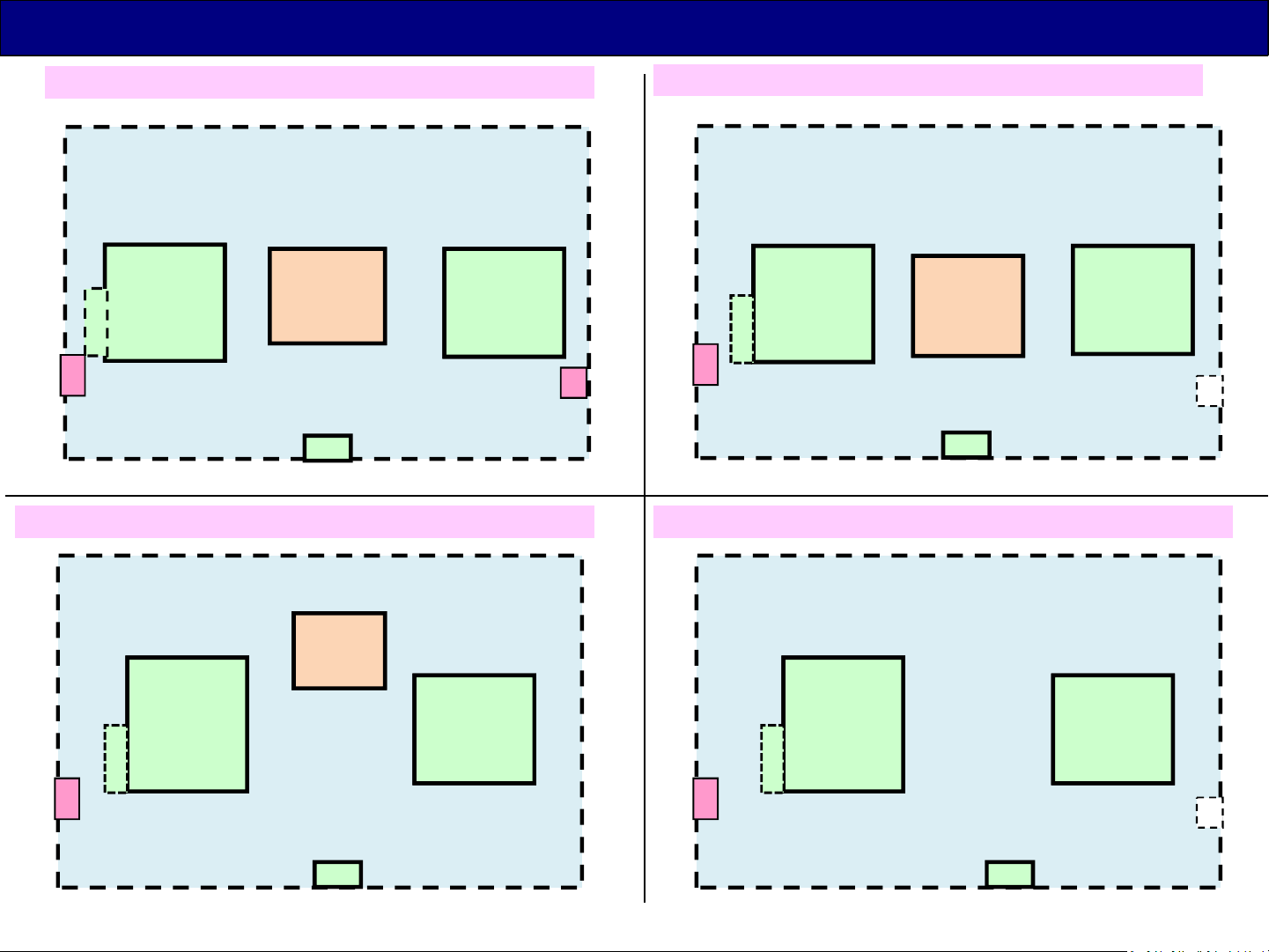
Board Layout -1 ( DX*** series )
T*-**DX900
G
K
WiFi
T*-40DX***
PB
K
T*-65DX***, TH/TC-55DX***
A P
BT
G
K
WiFi
P
PB
K
A
BT
T*-49/50/58DX***, TX-55DX***
LDP
G
K
WiFi
P
K
A
GK board : depend on the model
G
K
WiFi
BT : depend on the model and region
P
A
BT
K
5
Page 6
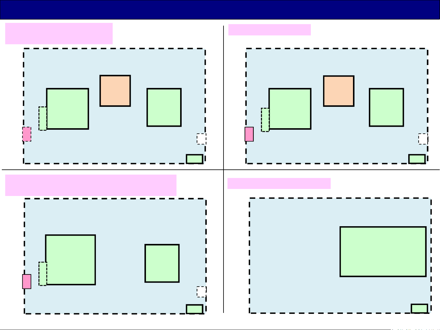
Board Layout -2 ( D/DS*** series )
T*-49/43DS***
T*-49/43D***
LD
G
K
WiFi
P
A
T*-50/40/32DS***
T*-40/32D*** (except 32inch India model)
K
T*-65/55DS***
LDP
G
K
WiFi
BT
P
A
BT
K
TH-32D450/440/400D
G
P
K
WiFi
WiFi : only DS*** series
A
K
BT : only TC-**DS6**, TX-**DS630 series
A
(P + A + GK)
BT
K
GK board : depend on the model
6
Page 7
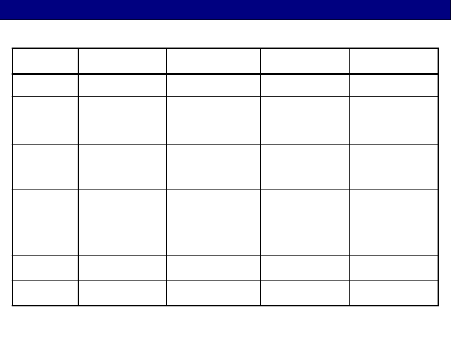
Main Board Structure
24inch
32inch
40inch
43inch
49inch
50inch
55inch
D4** DS4**/5**/6** DX6**/7**/8**
(4K)
--- A+P --- ---
A+P /
(India : 1 Board)
A+P A+P A+P+LDP ---
A+P+LD A+P+LD --- ---
A+P+LD A+P+LD A+P ---
--- A+P A+P ---
--- A+P+LDP A+P ,
A+P --- ---
A+P+PB: (only
TH-55DX640*,
TC-55DX700*)
DX900
(4K)
---
58inch --- --- A+P A+P+PB
65inch
--- A+P+LDP A+P+PB A+P+PB
Except K, GK boards
7
Page 8
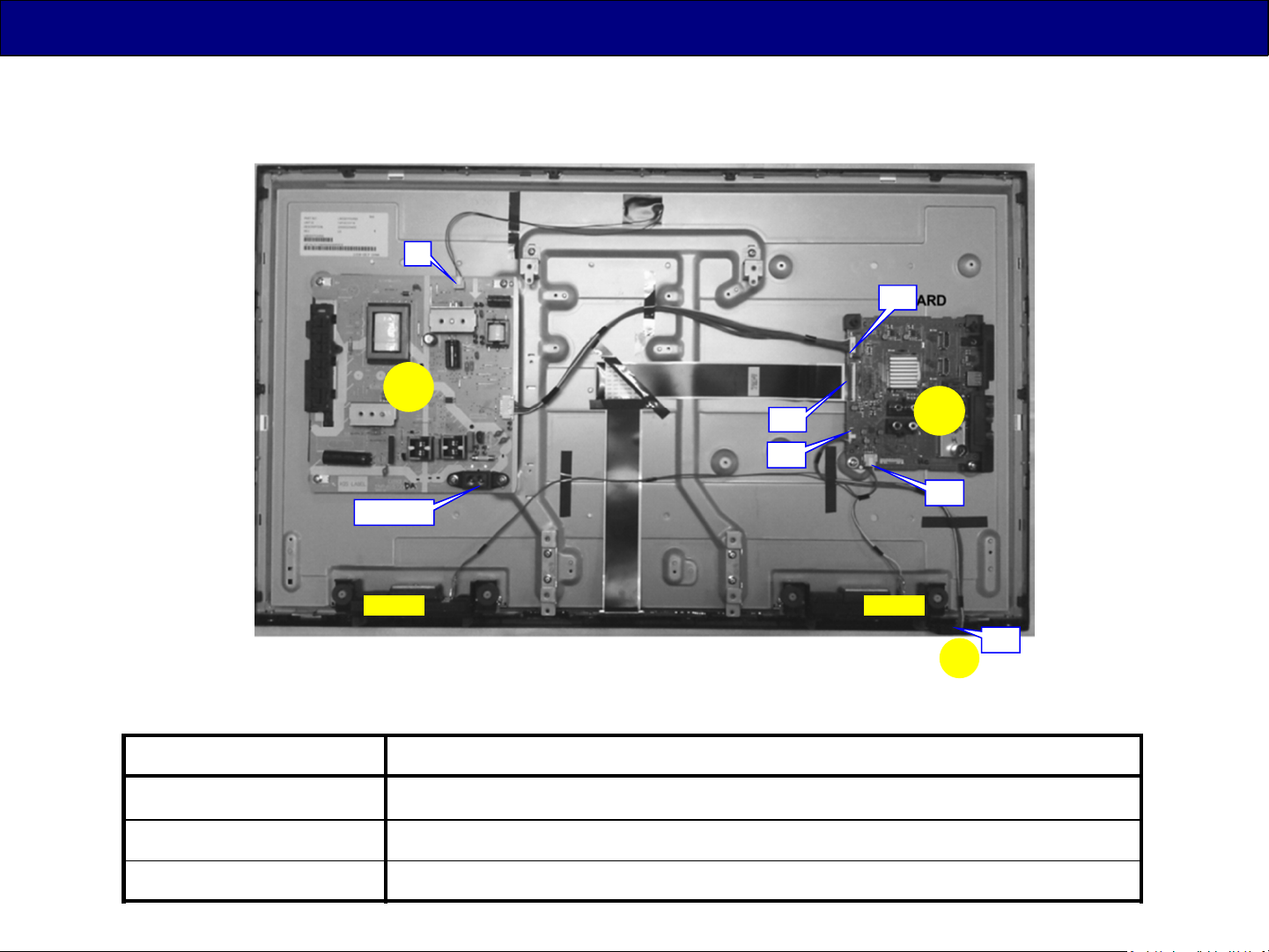
Board Layout -1
A+P
P3
P
AC input
A15
A10
( 32D410/400 )
A02
A
A12
Speaker Speaker
Board Name Function
A-Board Main Board
P-Board Power supply, Backlight Drive, Power key, Control key
K-Board Remote Receiver, LED
K10
K
8
Page 9
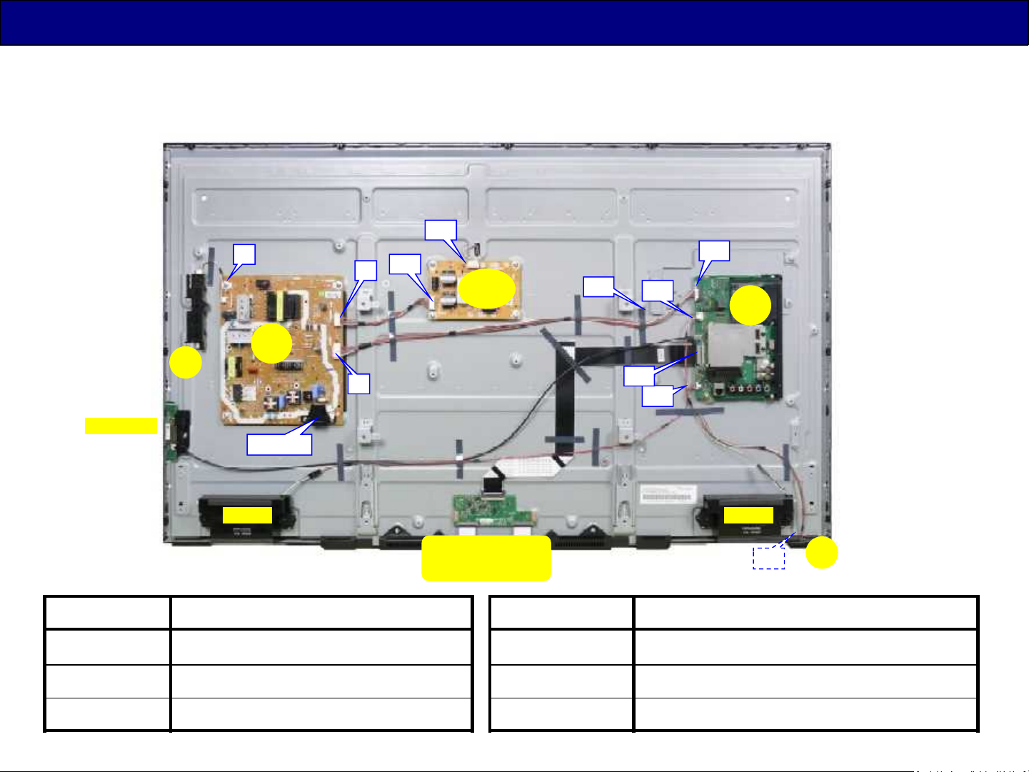
Board Layout -2
A+P+LD/LDP
GK
WiFi Module
P5
P
AC input
P2
P4
LD1
LD2
LD
A15
( 49DS630 )
A02
A10
A
A19
A12
Speaker Speaker
Board Name Function
A-Board Main Board
P-Board Power supply for Signal Process
LD-Board Power supply for Backlight Drive
(T-CON)
Not repairable,
One of the panel module
Board Name Function
GK-Board Key
K-Board Remote Receiver, Power LED
K10
K
9
Page 10
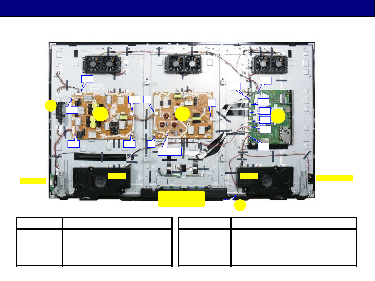
Board Layout -3
WiFi Module
GK
A+P+PB
PB1
PB5
PB2
P6
PB6
PB
PB3
Speaker Speaker
P3
AC input
P
P2
A02
A08
A15
A16
A17
A12
A10
( 65DX900 )
A
Bluetooth Module
Board Name Function
A-Board Main Board
P-Board Power supply for Signal Process
PB-Board Power supply for Backlight Drive
(T-CON)
Not repairable,
One of the panel module
Board Name Function
GK-Board Key
K-Board Remote Receiver, Power LED
K10
K
10
Page 11

2. Video Signal Processing
11
Page 12
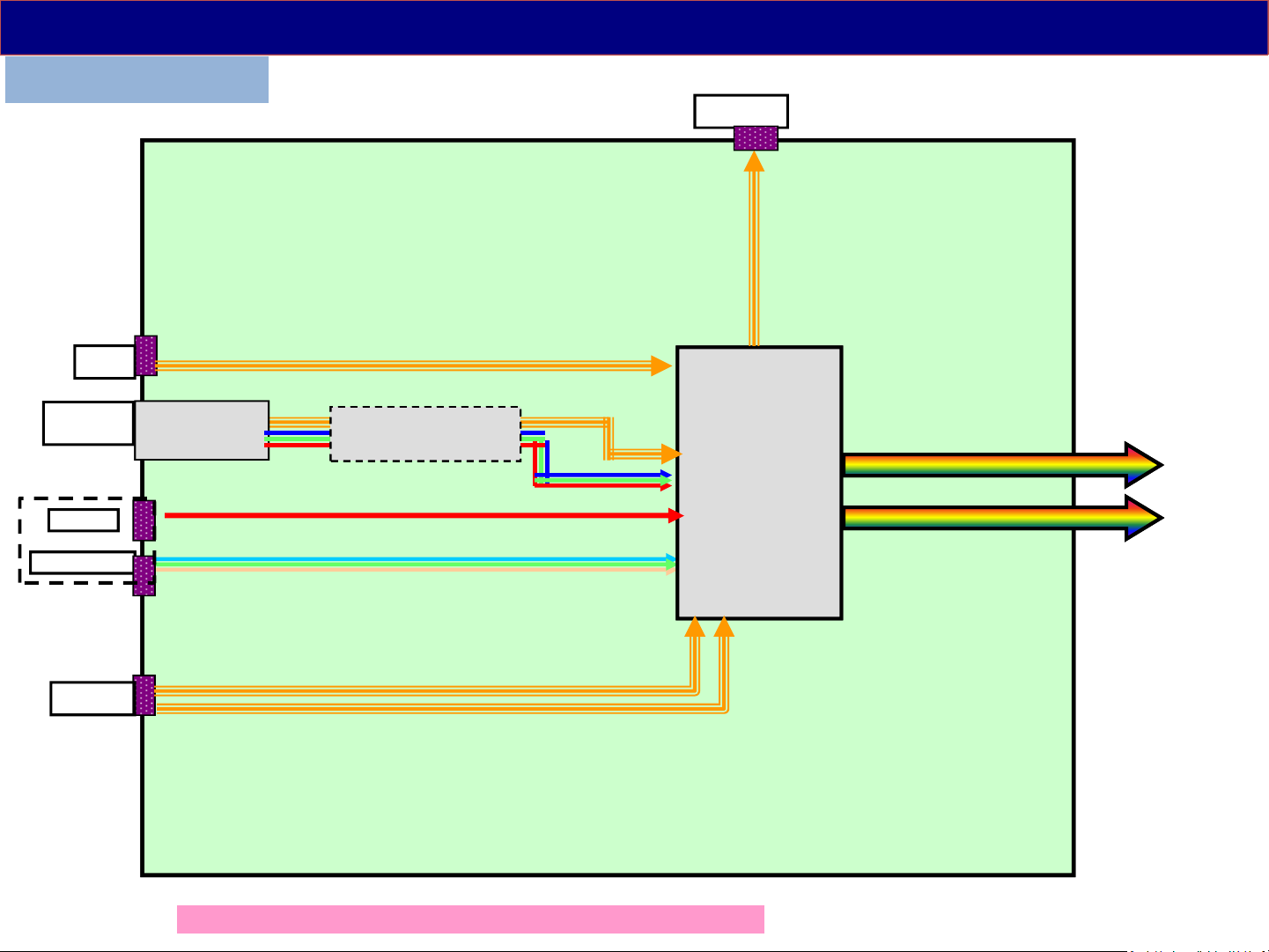
Video/Audio Signal Process - 1
D5** / D4** series
USB1
OPT_out
A
Antenna
terminal
AV
Component
HDMI1/2
TU670*
TUNER
IC68**
De-Modulation
IC8000
(MTK5561)
Resize
IP conv.
OSD
LVDS Data
to LCD Panel
The input terminals are different by the models or countries.
12
Page 13
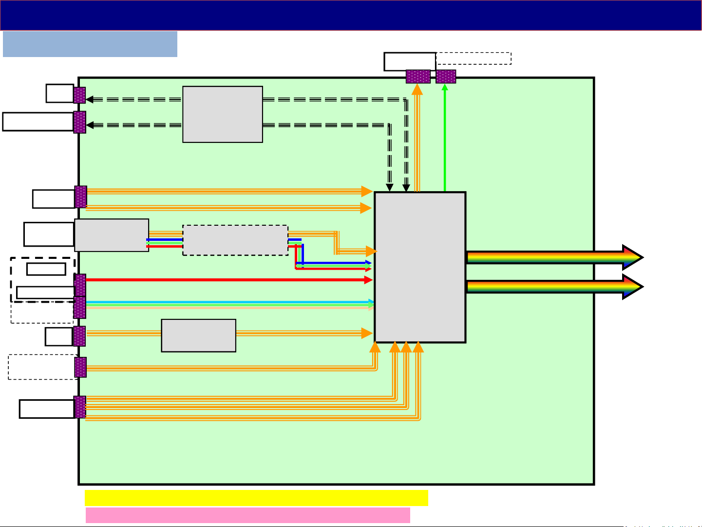
Video/Audio Signal Process - 2
DS5** / DS6** series
OPT_out
(*)Headphone
WiFi
(*1)Bluetooth
USB1/2
Antenna
terminal
AV
Component
SCART
(only Europe)
LAN
CI-slot
(only Europe)
TU670*
TUNER
IC8601
(USB HUB)
IC68**
De-Modulation
IC8650
(LAN)
IC8000
(Peaks LD6/
sLD8A)
Resize
IP conv.
OSD
A
LVDS Data
to LCD Panel
HDMI1/2/3
(*1) Bluetooth : only TC-**DS6**(except Canada), TX-**DS630*
The input terminals are different by the models or countries.
13
Page 14
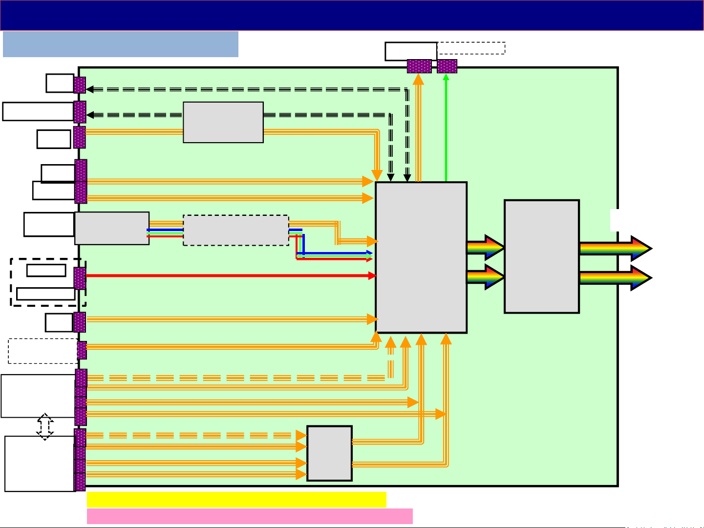
Video/Audio Signal Process - 3
DX6** / DX7** / DX8** series
WiFi
(*1)Bluetooth
USB2
USB1
USB3.0
Antenna
terminal
AV
Component
LAN
TU670*
TUNER
(USB HUB)
IC8601
IC68**
De-Modulation
OPT_out
IC8000
(MT5810)
Resize
IP conv.
OSD
2D->3D
(*)Headphone
IC9000
(Mstar/NTK)
Frame Rate
Convert
A
to LCD Panel
( V by One format )
CI-slot
(only Europe)
HDMI1/2/3/(4)
(except below
models
HDMI1/2/3/(4)
(TX-DX8**
TH-DX640
TC-DX700C)
IC4500
HDMI
SW
(*1) Bluetooth : only DX9**/7** (except TC-**DX700C)
The input terminals are different by the models or countries.
14
Page 15
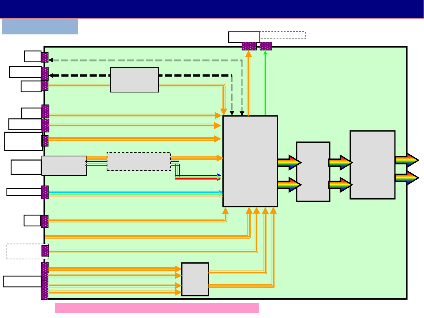
Video/Audio Signal Process - 4
DX900 series
OPT_out
(*)Headphone
WiFi
Bluetooth
USB2
USB1
USB3(3.0)
SD card
(only TC/TX
Antenna
terminal
Component
LAN
TU670*
TUNER
IC8705
(USB HUB)
IC68**
De-Modulation
IC8000
(MT5810)
Resize
IP conv.
OSD
2D->3D
IC4300
(GCEX2)
HDR
Hexachroma
A
to LCD
IC9000
(NTK)
Frame Rate
Convert
( V by One format )
Panel
CI-slot
(only Europe)
HDMI1/2/3/4
IC4500
HDMI
SW
(*) The input terminals are different by the models or countries.
15
Page 16

Video/Audio Signal Process - 5
The main function of the A board is to select and process one of the incoming video signals.
IC8601 is just switches of USB signals. The built in WiFi module is connected by USB type
terminal.
Video input, Component Video Input, HDMI input and the composite video output of the tuner
are all connected to IC8000 for selection. The video input signal can be two formats: Video, or Y,
Pb, Pr. A comb filter inside IC8000 converts the composite video signal of the main picture to Y
and C (luminance and chrominance) signals. The signal is then converted to RGB. At the
completion of this process, the format of the composite signal is now the same as a digital 1080i
component signal. If the incoming video is in the 480p, 720p, 1080i, and 1080p format, the Y, Pb,
and Pr signals undergo A/D (analog to digital) conversion. Finally all picture signals are
converted to 1080p.
Digital television reception of the tuner is output in the form of an IF (Intermediate Frequency)
signal. The transport stream from the tuner enters the VSB I/F (Interface) section of IC8000 where
the video signal is extracted and converted to YUV data. The output is provided to the Video Input
I/F for selection. The JPEG data of the SD card enters the JPEG I/F section of IC8000 for
conversion into YUV data and output to the Video Input I/F circuit. The video input interface
outputs the selected picture data to the video process circuit.
This Video Process section of the IC performs all picture control operations such as brightness,
contrast, color, tint, etc. On Screen Display data such as channel numbers, Digital TV closed
caption, and picture adjustments are mixed with the video data. If in 3D mode, it converts to the
right and left pictures. After the process, LVDS (Low Voltage Differential Signaling) is output to
LCD panel module. # IC9000 is the frame rate converting IC for high speed LCD panel. IC4300
adjust the brightness for HDR feature.
16
Page 17
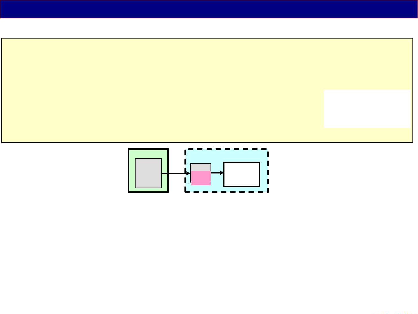
When abnormal picture is displayed, troubleshoot by the test pattern in LCD module.
Troubleshoot for Video Signal Problem
<LCD Panel Test Mode> :
If the picture is no problem, A board must be defective.
If the picture is also abnormal, LCD panel module must be defective. Just in
case, confirm the flat cable connection between A board and T-CON board.
How to enter :
While pressing "volume(-)" button of the TV unit,
press "option/yellow" button of the remote control 3 times within 2 seconds.
How to exit :
Switch off the TV unit
#)The test pattern is created by the circuit in LCD Panel Module(T-CON board).
Some patterns are
automatically changed.
The patterns are depend
on the LCD panel.
A
IC8000
(Peaks/MTK )
Resize
IP conv.
LCD Panel Module
T-CON
Test
Pattern
LCD Panel
17
Page 18
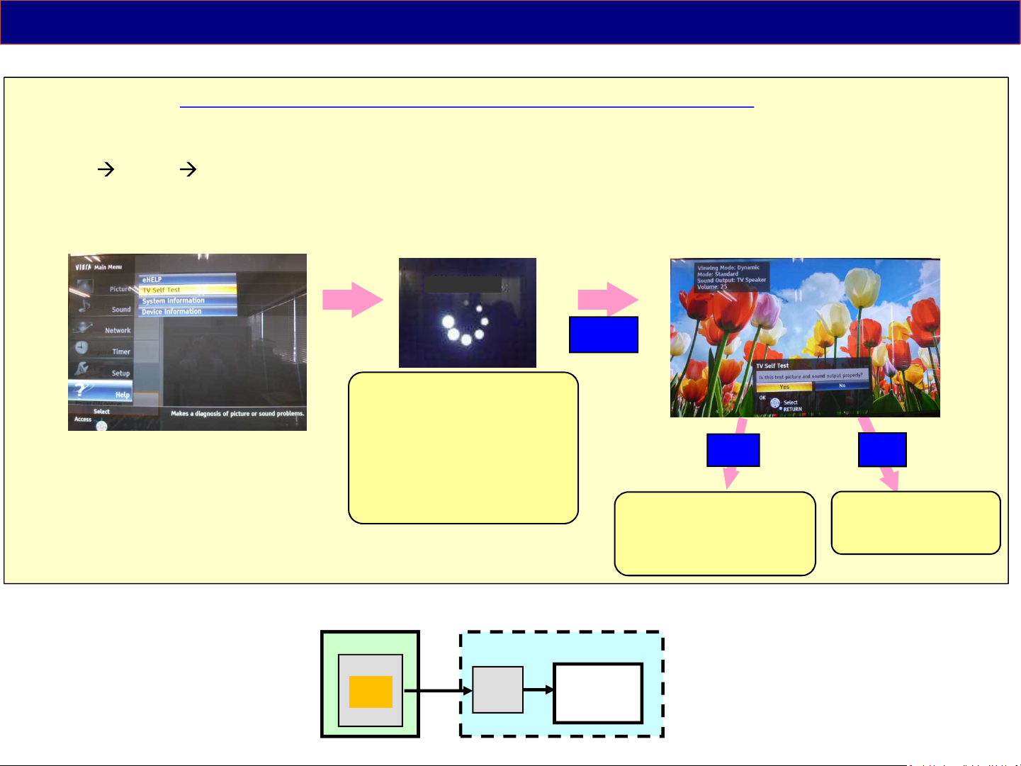
Troubleshoot for Video/Audio Signal Problem
<TV Self Test> : Customers also can check the picture and sound by internal data.
If the picture and sound is no problem, the reason of trouble is mostly not a TV.
How to display :
Menu HELP TV Self Test
#)The test pattern and test sound are created by the main IC on the A board.
TV Self Test
(OK)
1) During this indication
“Self Check of Service Mode”
is working at the background.
*) D400/410 series do not support.
2) If NG, indication is shown.
# A board defective
3) If All OK, it shifts to picture
and sound test.
1.Antenna level low
2.Connection mistake
3.Input devices NG
4.Input select mistake
Yes
No
TV unit defective.
(A board, Panel or
Speaker)
A
IC8000
(Peaks/MTK )
Test
Pattern
Resize
IP conv.
LCD Panel Module
T-CON
LCD Panel
18
Page 19

3. Power Supply
3-1. Power Board Structure
19
Page 20
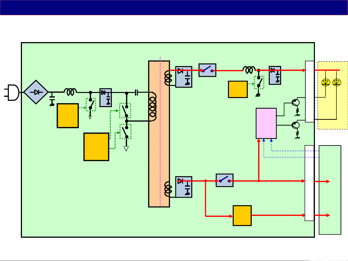
Power Board Structure 1 ( P Board only )
< P >
VLED
Anode
Power
IC
P
PFC
IC
Power
IC
HO
LO
16V
REG
LED
Drive
IC
PWM
BL-ON
BL-ON
16V
STB5V
Cathode
(Backlight)
A
20
Page 21
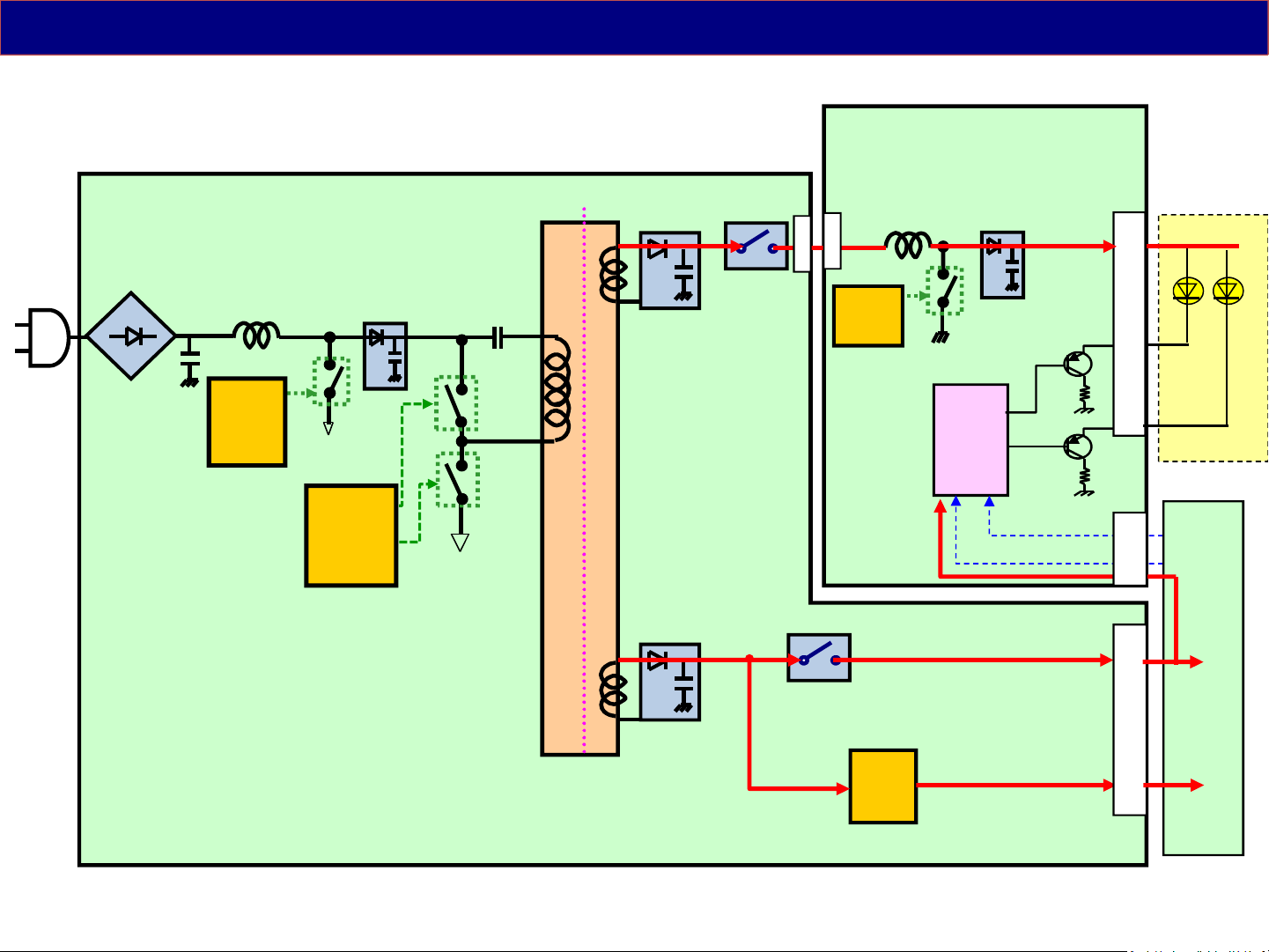
Power Board Structure 2 ( P+LDP/LD board )
< P + LDP/LD >
LDP/LD
VLED
Anode
Power
IC
P
PFC
IC
Power
IC
HO
LO
16V
REG
LED
Drive
IC
PWM
BL-ON
BL-ON
16V
STB5V
Cathode
(Backlight)
A
21
Page 22
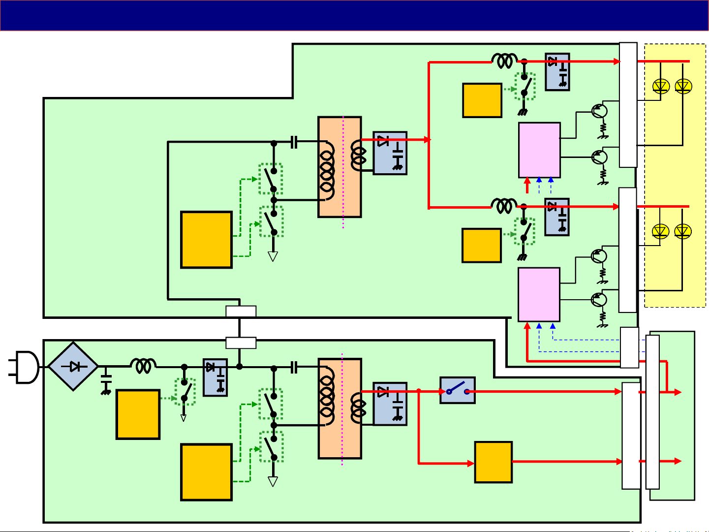
Power Board Structure 3 ( P+PB board )
< P + PB >
only 65DX7**/8**
(TNPA6249)
PB
HO
Power
IC
LO
Power
IC
Power
IC
LED
Drive
IC
LED
Drive
IC
VLED1
VLED2
PWM
BL-ON
Anode
Cathode
Anode
Cathode
(Backlight)
A
P
PFC
IC
(TNPA6060)
HO
Power
IC
LO
16V
16V
REG
STB5V
22
Page 23
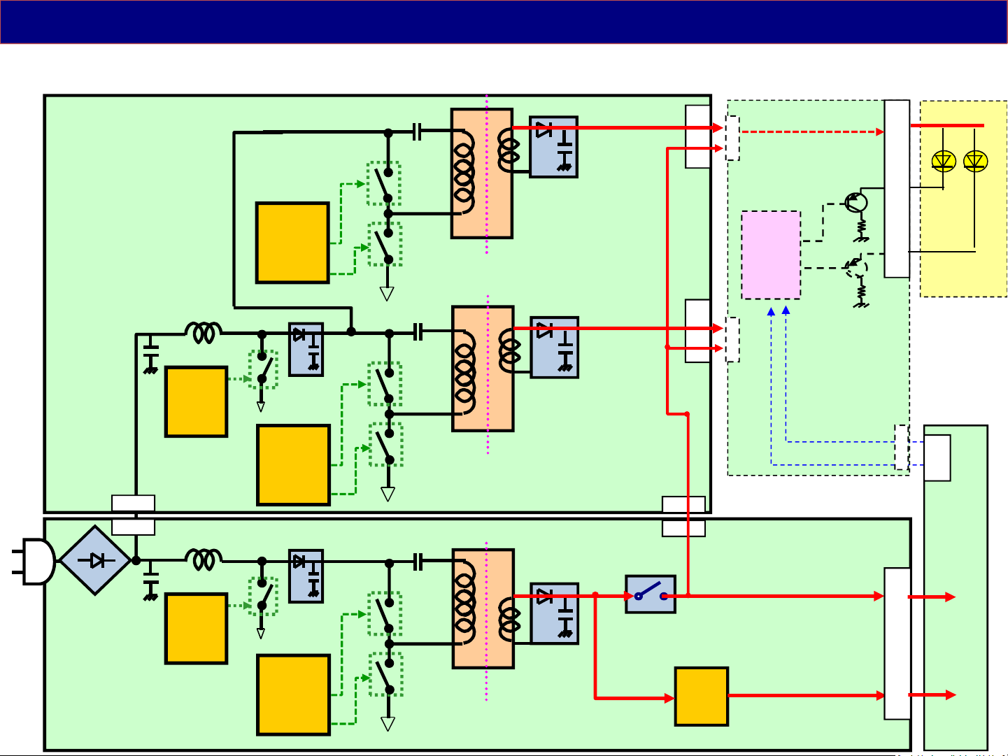
Power Board Structure 4 ( P+PB board )
< P + PB >
(TNPA6200)
PB
PFC
IC
only DX9**
HO
Power
LO
IC
HO
Power
LO
IC
VLED1
VLED2
LED
Drive
IC
Anode
Cathode
(Backlight)
Sync/control/etc
BL-ON
A
(TNPA6199)
P
PFC
IC
HO
Power
IC
LO
16V
16V
REG
STB5V
23
Page 24

3-2. Stand by / Start up Operation
The explanation is for the case of “Power Board Structure 2 (P+LD/LDP board,
43/49DS630 )”, but “P, P+LD/LDP, P+PB” cases are basically same start up operation.
24
Page 25
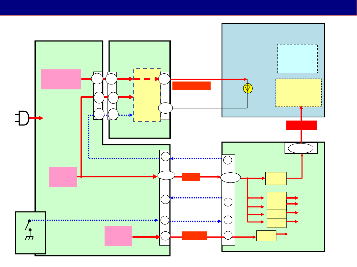
Voltage Distribution ( A+P+LD Boards )
Ex. 43/49DS630** series
(Each models are different pin allocation but operation is same.)
P
28V/32V(*)
Output
P4
8,9
LD
LD1
8,9
LD2
3,7
VLED1,2(*)
LED
6
16V
6
3
3
(Ex. TNPA5935** )
Drive
1,5
11
1,2,3
P2
BL_ON
16V
Output
LCD Module
A02
10
F15V
1,3,5
12V
LCD Panel
T-CON
board
PNL12V
A19
1,2,3,4
PNL12V
GK
POWER
Switch
(Ex. TNPA5916** )
9
12
TV_SUB_ON
POWER_ON
2
4
STB5V
7
STB5V
11
Output
(*)The DC level is different by the LCD panel.
5V
3.3V
1.5V
1.1V
3.3V
A
STB3.3V
25
Page 26
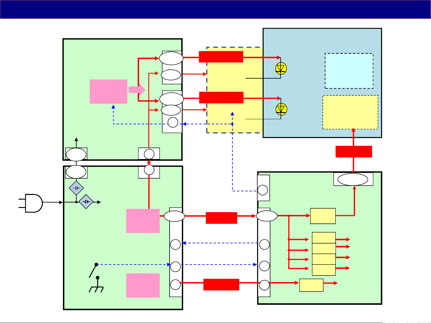
Reference : Voltage Distribution ( A+P+PB Boards )
Ex. DX900** series
(TNPA6200** )
PB
PB2
17-28
VLED2(*)
LCD Module
PB6
P6
VLED(*)
Output
1 / 3
1 / 3
P
POWER
Switch
(TNPA6199** )
BL_ON
PB3
P3
16V
Output
STB5V
Output
16V
9,10
LED
16V
LCD Panel
Drive
17-28
9,10
5
PB1
1
1
1-5
11 11
12
9
VLED1(*)
16V
P2
TV_SUB_ON
POWER_ON
16V
5VS
BL_ON
15
1-5
12
9
A03
A02
F15V
3.3V
A16
12V
5V
3.3V
1.5V
1.1V
STB3.3V
T-CON
board
PNL12V
44 - 51
PNL12V
A
(*)The DC level is different by the LCD panel.
26
Page 27
Start up Operation-1
Ex. 43/49DS630** series
Transformer
P
PFC
T7202
IC7201
DC/DC
IC7301
T7301
24V/32V(*)
Output
16V
Output
Q7402/05
(Each models are different pin allocation but operation is same.)
24V/
32V(*)
Q7403
LD1P4
L7813/14/
Q7804/01
(DC/DC)
LD
LED
Drive
IC7800
LD2
3,7
1,5
P2
11 10
1,2,3
VLED1,2(*)
6(light)
6(light)
3
3
BL_ON
16V
5
LCD Module
Power
For
LED
(Back
Light)
A02
A19
1,3,5
F15V
1
DC/DC
IC7503
7
STB5V
2
2
11
STB5V
LCD Panel
T-CON
board
PNL12V
4
1,2,3,4
A
POWER
Switch
9
TV_SUB_ON
12 4
POWER_ON
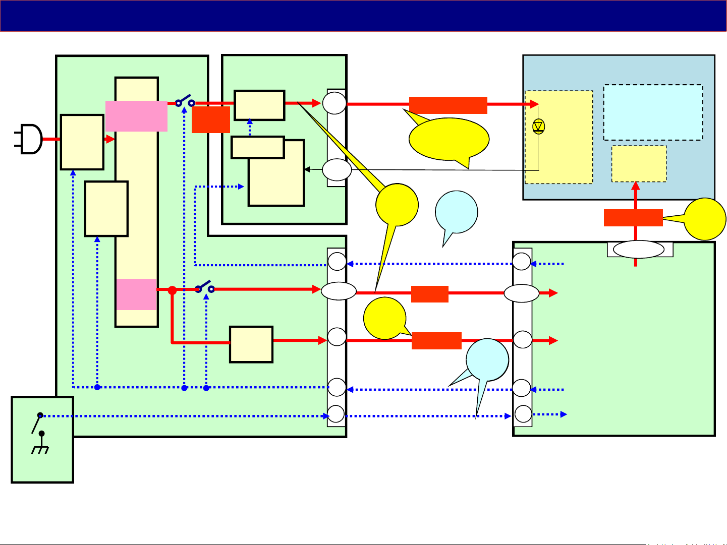
When the TV is plugged in, the power board outputs 5V for standby voltage.
When the power supply receives the TV_SUB_ON signal, it outputs 2 different voltages:
•16V to the A board on pins 1, 2, and 3 of connector P2.
•24/32V to the LED backlight board on pins 8,9 of connector P4.
After A board is ready to display, it outputs Backlight_on command to LD board.
2
KEY3
27
Page 28
Start up Operation-2
< from AC plug in to : P board >
1
Ex. 43/49DS630** series
( TNPA5916** )
( PFC = OFF
AC100V: 140V
AC240V: 330V)
VCC
feedback
D7106
Rectifier
D7104,
7105
R7104-
7105
( Through )
T7202
7
PFC
IC7201
( OFF )
Start Vcc
VH
1
HO
LO
VCC
IC7301
D7215
C7213
15
11
10
4
FB
REF
6
Q7301
Q7302
PC7301
PC7303
T7301
D7401/02
C7422
D7408/09
C7423
IC7401
Q7402/05
( OFF )
24V/32V(*)
Q7403
16V
( OFF )
LD
2
IC7503
6
CE
LED
Drive
IC7800
STB5V
Anode1
Anode2
Cathode1
Tr
Cathode2
Tr
LD2
3
7
1
5
11
13
1 - 3
7
P
P2
28
Page 29
Start up Operation-3
< from AC plug in to : P board >
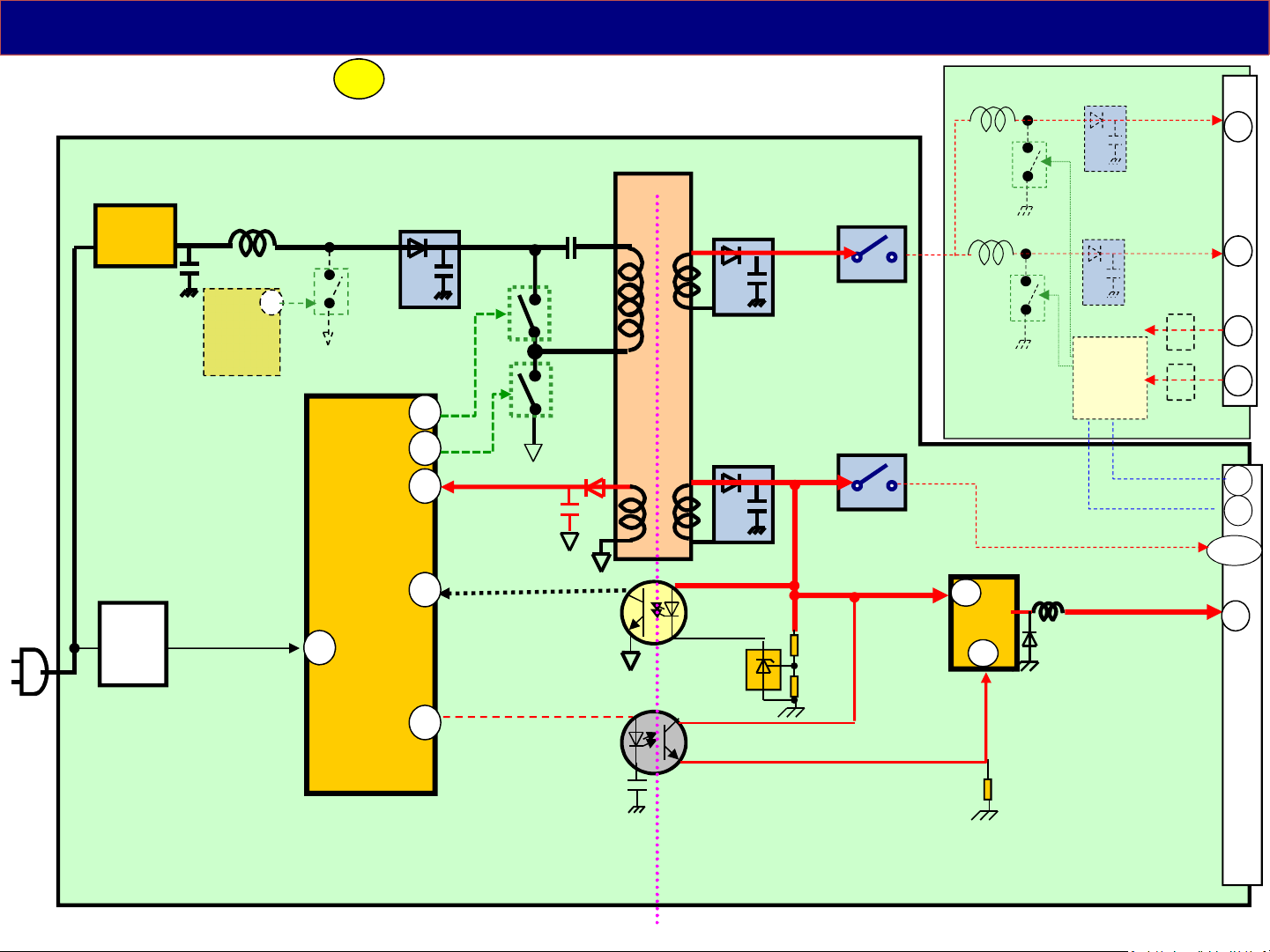
When the TV is plugged in, the rectifier start to produce DC voltage which leads
through PFC circuit directly to the power switches Q7301, Q7302. (PFC circuit
IC7201 does not operate at this moment.) Besides this DC voltage is provided also for
D7104, D7105 which provide start voltage to pin 1 of power supply IC 7301. When
the voltage on pin 1 rise up to predefined value IC7301 starts supplyinng of switching
pulses for Q7301, Q7302. Due to this current starts to lead through winding of T7301
which starts to generate output voltages. One of these voltages VCC is used for
power supplying of the IC 7301 to its pin 10.
When the power supply starts up, the 16V is providing by D7408,09/C7423. This
voltage leads to IC7503, which is 5 volts DCDC converter.
This voltage (STB5V) is provided to A board via connector P2 pin7. So if the TV is
1
plugged in, STB5V is provided to A board without trigger signal.
29
Page 30
Start up Operation-4
< from to : A board >
1
2
Ex. 43/49DS630** series
P A
P2
9
5VS
IC7503
12
POWER
Switch
A02
2
117
STB5V
4
LCD_TV_SUB_ON
IC5000
STB3.3V
3.3V
KEY3
IC8000
PEAKS
Signal
Processing
LED_on
K
A11 K10
1 7
5
3.3V
3
REMOTE
LED
(Each models are different pin allocation but operation is same.)
OFF
(It can receive only Power SW)
North America Power LED: OFF
Except North America Power LED: OFF Power LED: RED
( Automatically )
Power SW on
Standby
(It can receive Power SW, Remote, Viera Link and so on)
30
Page 31
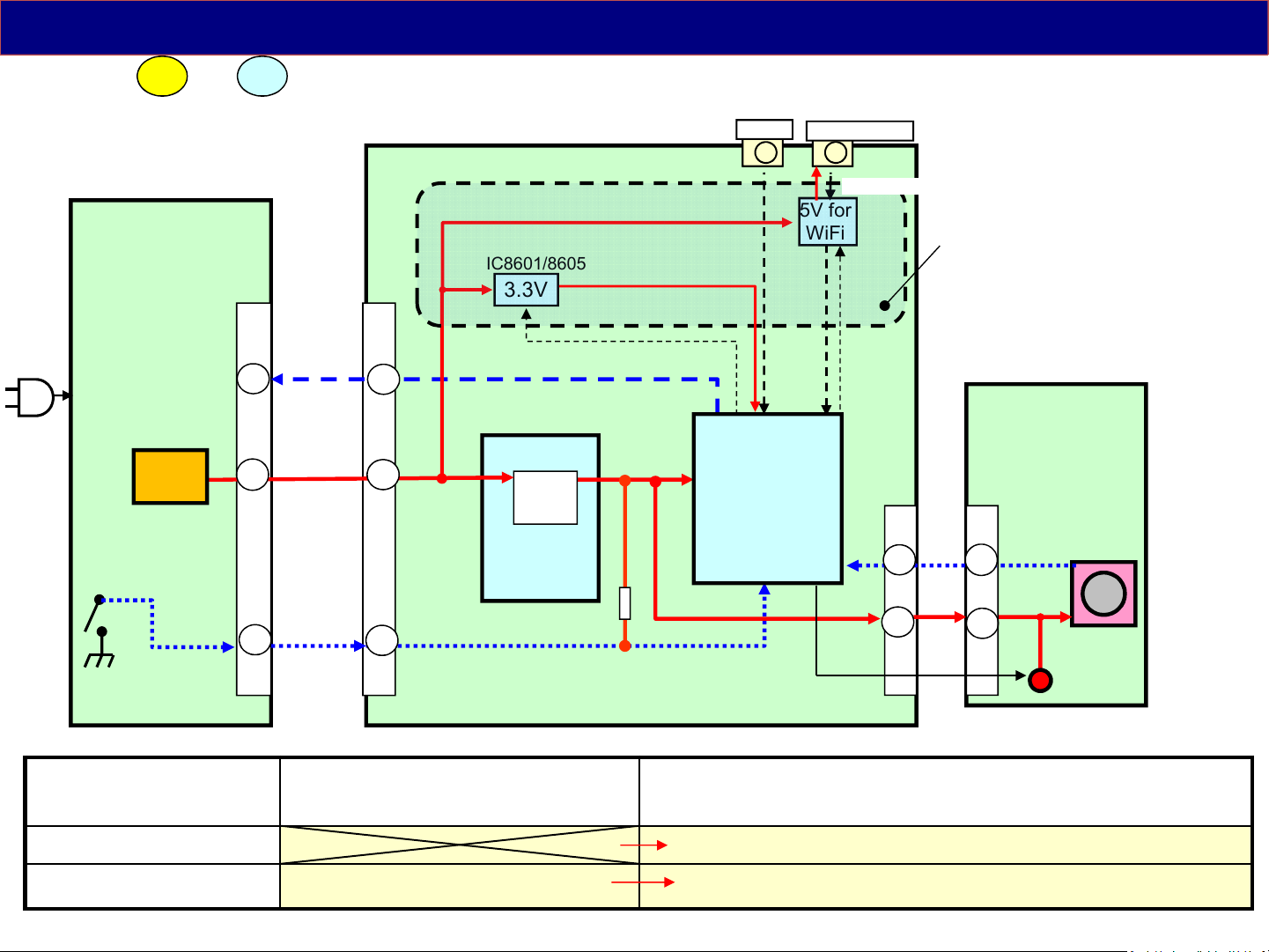
( Reference ) Start up Operation-4
< from to : A board >
1
2
(4K models except Taiwan, Hong Kong, Brazil and USA.
And TX-**DS630 )
A
P
IC7503
P3
11
5VS
A02
11
99
STB5V
IC8601/8605
3.3V
LCD_TV_SUB_ON
IC5000
3.3V
Enable
PHY3.3V
STB3.3V
LAN
JK8600
JK8705/8605
1
5V for
WiFi
IC8000
PEAKS
Signal
Processing
To WiFi adaptor
1
IC8706/8607
Enable
A10 K10
12 7
The power line for LAN/WiFi
is supplied from Standby power.
*) It is for “Power on by
Apps”, Power on by Easy
Mirroring etc. function.
K
REMOTE
8
12
POWER
Switch
OFF
(It can receive only Power SW)
North America Power LED: OFF
Except North America Power LED: OFF Power LED: RED
12
KEY3
LED_on
Standby
(It can receive Power SW, Remote, Viera Link and so on)
( Automatically )
Power SW on
3
3.3V
LED
31
Page 32

Start up Operation-5
< from to : A board >
1
2
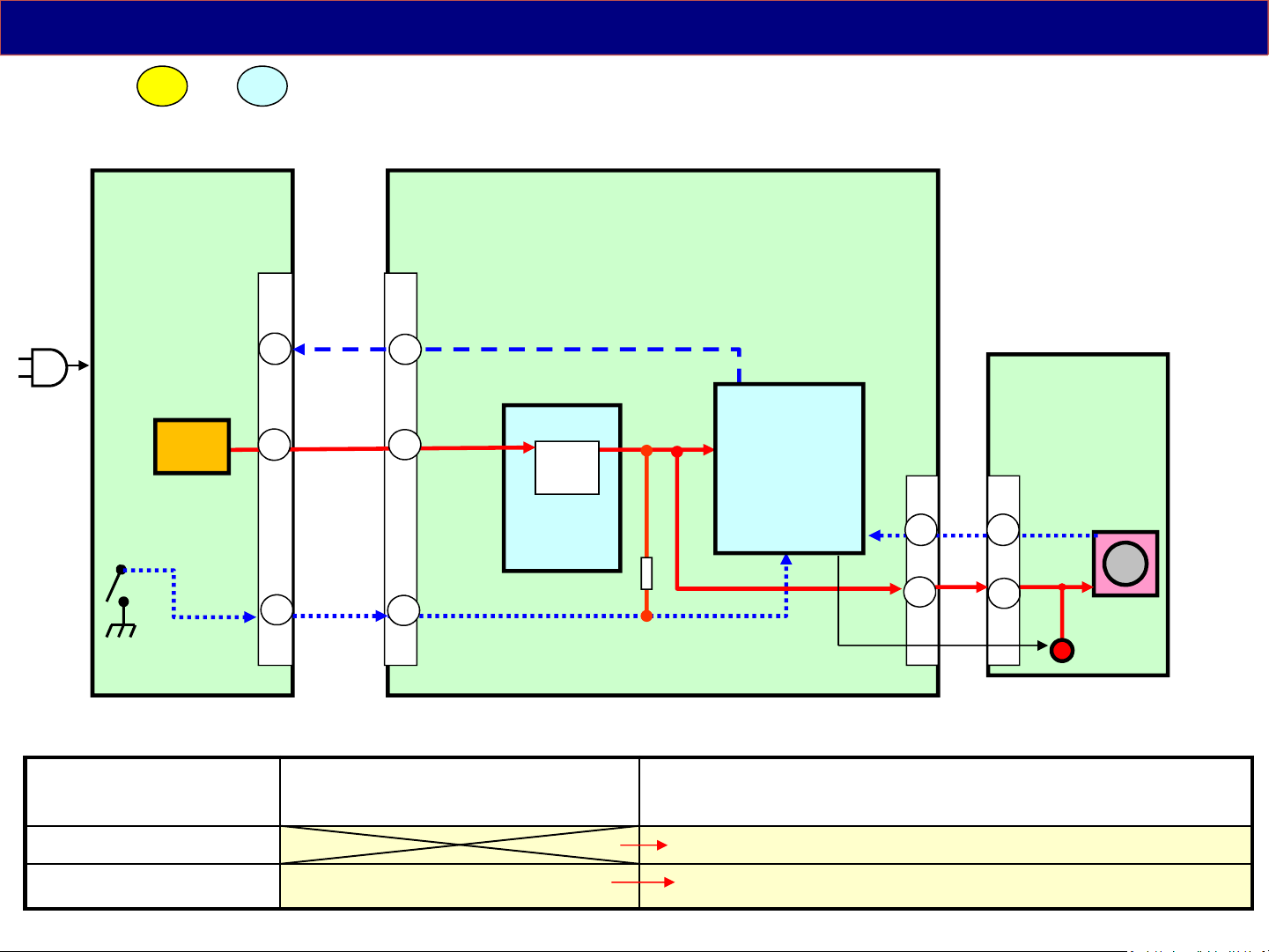
The STB5V from pin7 of connector P2 is applied to the Analog ASIC (IC5000) for
supplying power to the Main CPU/PEAKS (IC8000) on the A board. The Analog ASIC
(IC5000) converts the STB5V to STB3.3V. This voltage energize and prepare the
microprocessor (CPU) for program execution. The STB3.3V from the Analog ASIC (IC5000)
is also applied to the remote control receiver and the power LED on the K board through pin
5/8 of connector A11/K10.
When the Power Switch on, the key3 signal is grounded. (#1)
The IC8000 lights on the RED LED and is ready to power on the TV by receiving the Power
switch on, Remote on, Viera Link and so on. This is a standby state.
(#1)Only North America model: Power switch on is no need, automatically this procedure is
operated after the TV is plugged in. But the RED LED does
not light.
When the power on command from the power switch, the remote control and so on is
provided to IC8000 PEAKS, IC8000 first outputs the “TV_SUB_ON” command. The
“TV_SUB_ON” command is provided to power board via pin 9 of connector P2.
(#) Just after transition to Stand-by mode, the TV_SUB_ON(16V) output for few minutes.
(North America model : 10s)
32
Page 33
Start up Operation-6
< from to : P/LD board >
2
3
Ex. 43/49DS630** series
( TNPA5916** )
( PFC = ON
AC100V: 380V
AC240V: 380V)
VCC
feedback
D7106
Rectifier
D7104,
7105
R7104-
7105
Q7202
Start Vcc
T7202
PFC
IC7201
8
VCC
7
Q7201
IC7301
VH
1
5
CS
(mode change)
D7215
C7213
HO
LO
VCC
REF
15
11
10
4
FB
6
Q7301
Q7302
PC7301
PC7303
T7301
D7401/02
C7422
D7408/09
C7423
IC7401
SRV-VLED
Q7402/05
24V/
32V(*)
16V
Q7403
P4
8,9
LD1
L7814
Q7804
L7813
Q7801
LD
SRV-16V
2
IC7503
6
CE
SRV-VLED1
SRV-VLED2
LED
Drive
IC7800
Vcc
BL-ON
PWM
16V
STB5V
SRV-5.3V
Anode1
Anode2
Cathode1
Tr
Cathode2
Tr
LD2
3
7
1
5
11
13
1 - 3
7
P
Q7303
PC7302
Standby/ON
L=ON
Switch
Q7401
(*)The DC level is different by the LCD panel.
P2
9
SUB-ON
33
Page 34

Start up Operation-7
< from to : P board >
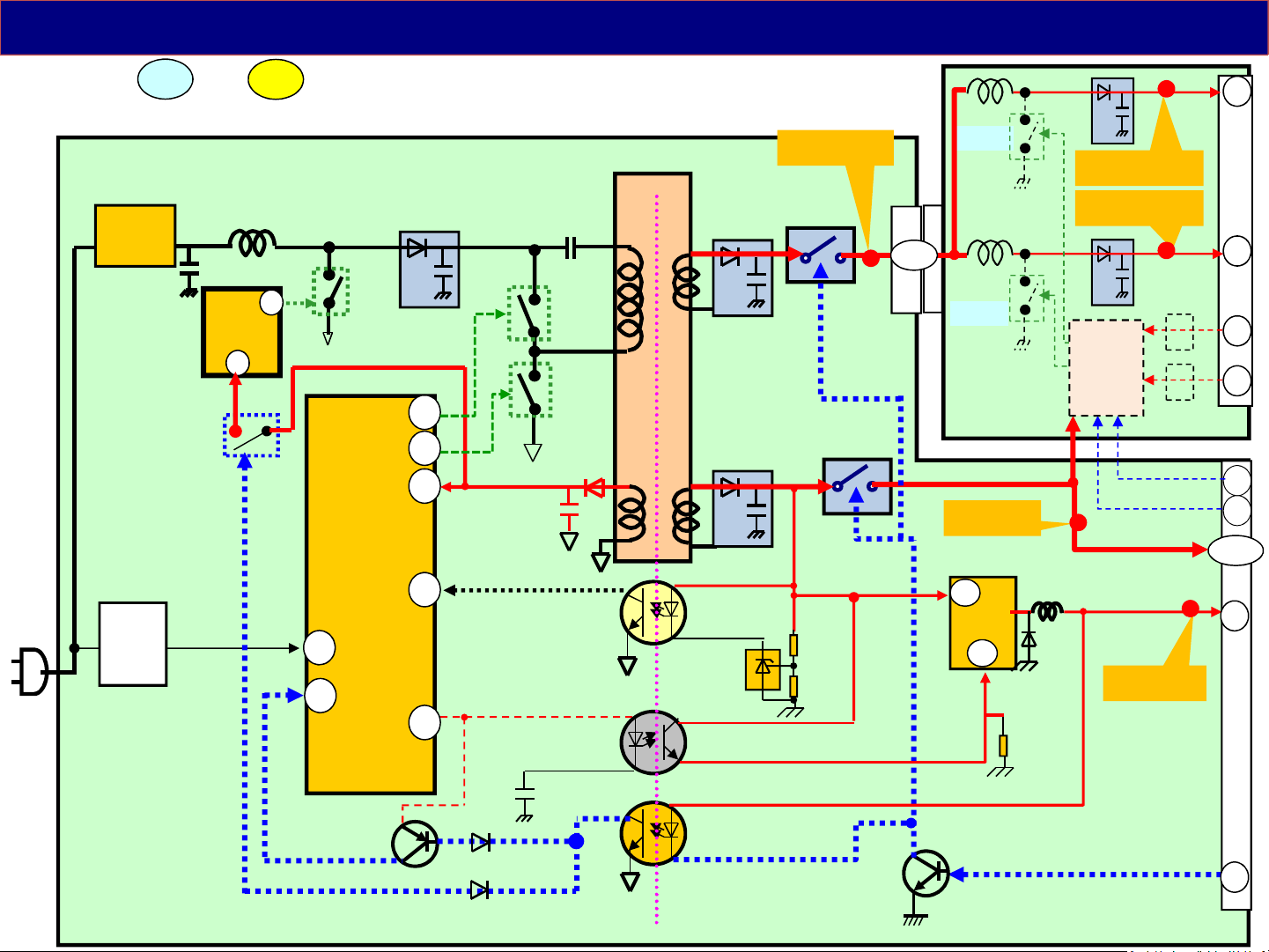
connector P2, it outputs 2 different voltages:
TV_SUB_ON command is carried to the primary side by PC7302. This voltage is leaded
to Q7303 whcih provide the mode change signal to pin 5 of IC7301.
Therefore the operation of the IC 7301 changes the switching frequency from standby
state to working state and output voltages rise up.
of PFC circuit. The PFC starts to operate then.
2
When the power board receives the TV_SUB_ON signal from IC8000 via pin 9 of
16V to the A board on pins 1, 2 and 3 of connector P2.
24/32V(*) to the LED backlight board on pins 8,9 of connector P4.
Besides the ON command is connected to the Q7202 which provide power supply VCC
3
Output voltages from transformer T7301 start rising up until the moment when IC7401
started to operate. This IC measures the 16V line output in the secondary side. The
output of this IC is provided by PC7301 to pin 4 of IC7301. IC7301 adjust the switching
frequency by this feedback signal.
The TV_SUB_ON signal also switches on the Q7402/03/05 to provide output voltages
(16V and 24/32V(*) ) to other boards. The 24/32V(*) is provided to the LD Board for
LED Backlight Drive. The 16V is provided to the A board.
(*)The DC level is different by the LCD panel.
34
Page 35
Start up Operation-8
< : A board (SUB voltage) >
3
Ex. 43/49DS630** series
3, 7
VLED1/2(*)
DCDC LED
LD1
8,9
P4
(*)
Q7402
/05
IC7800
Drive
16V
6
DC/DC
IC7503
16V
Q7403
PFC
T7202
IC7201
DC/DC
IC7301
LD2
24/32V(*)
LD
24/32V
Output
Transformer
T7301
16V
Output
P
( TNPA5916** )
P2
A
IC8000
PEAKS
SRV-16V
29
7
1
2
3
11
1
3
5
A02
STB5V
F15V
IC5420
5V
F15V
DCDCEN
LCD_TV_SUB_ON
IC5000
ANALOG
ASIC
3.3V
STB3.3V
IC8001
HDMI3.3V
SUB5V
(*)The DC level is different by the LCD panel.
IC5400
3.3V
1.1V
1.5V
IC8100
IC8101
1.8V
IC5701/04
SUB3.3V
TU1.8V
SUB1.1V
SUB1.5V
35
Page 36

Start up Operation-9
< : A board (SUB voltage) >
3
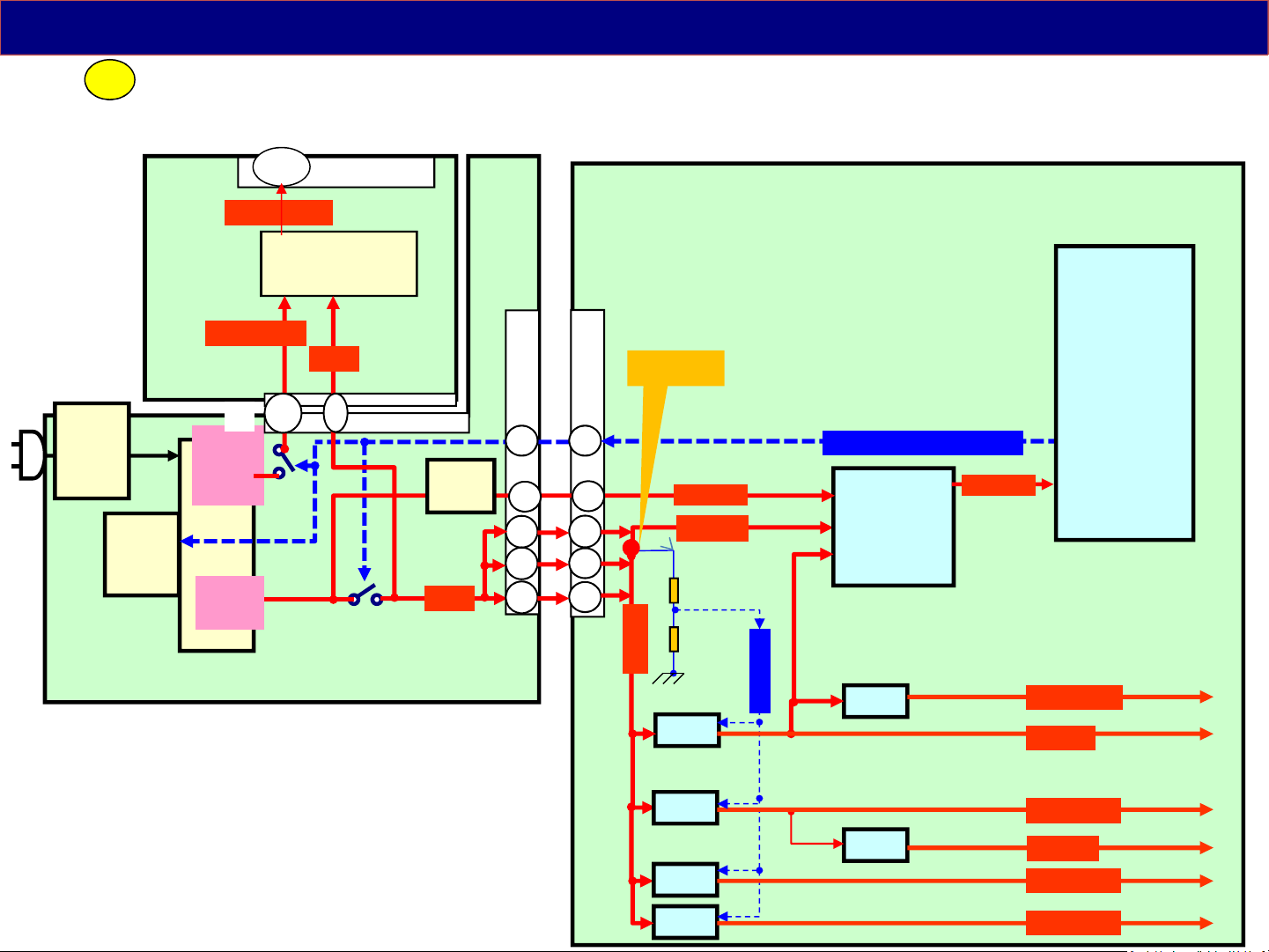
The 16V(F15V) from the P board via pin1,3 and 5 of connector A02 is applied to Analog
ASIC IC5000 and ICs (Voltage regulators) on the A board to generate the SUB-Voltages
used for signal processing operation.
: SUB1.1V, 1.5V, 3.3V, 5V and HDMI3.3V, TU1.8V
Each voltage regulators start up by high state of DCDCEN signal which is pull up to F15V.
So F15V is provided to A board, each SUB-voltage regulator ICs start output.
36
Page 37
Start up Operation-10
< and : A board (PNL voltage) >
4
LD
PFC
T7202
IC7201
DC/DC
IC7301
P
( TNPA5916** )
5
LD2
24/32V(*)
24/32V
Output
Transformer
T7301
16V
Output
3, 7
VLED1/2(*)
LD1
P4
(*)
1, 5
IC7800
DCDC LED
Drive
16V
8,9
6
Q7402
/05
Q7403
Back Light
4
2
3
DC/DC
IC7503
16V
14
13 12
11
7
1
2
3
P2
LCD Module
8
10
29
11
1
3
5
A02
IC5500
F15V
STB5V
F15V
IC5420
5V
12V
F15V
PNL12V
PWM
DCDCEN
T-CON
1
2 3 4
Panel_VCC_ON2
BL_SOS
BL_ON
LCD_TV_SUB_ON
IC5000
ANALOG
ASIC
IC8001
3.3V
A19
STB3.3V
A
IC8000
PEAKS
HDMI3.3V
SUB5V
(*)The DC level is different by the LCD panel.
IC5400
3.3V
1.1V
1.5V
IC8100
IC8101
1.8V
IC5701/04
SUB3.3V
TU1.8V
SUB1.1V
SUB1.5V
37
Page 38

Start up Operation-11
< and : A board (PNL voltage) >
< : LD board ( backlight drive ) >
4
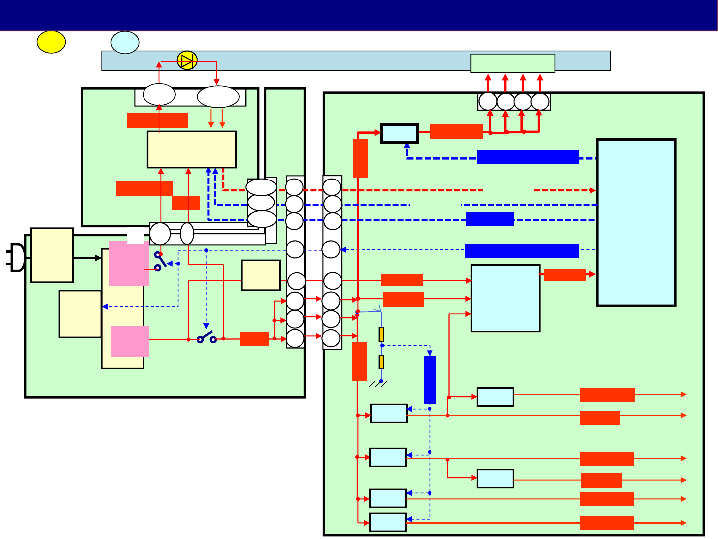
The F15V is also used to generate the PNL-Voltage on A board. IC8000 outputs the
Panel VCC On2 signal. IC5500 starts generating the PNL12V by this signal. The
PNL12V is provided to T-con circuit of the LCD Module.
6
After that, IC8000 outputs the BL_ON command to the LD board through P board. The
BL_ON command turns on the IC7800 for LED backlight drive. Then the backlight starts
5
lighting by PWM signals, and LCD panel displays the pictures.
If the backlight drive circuit does not work normally, the BL_SOS signal is informed to
the IC8000. At that time, IC8000 stops outputting the TV_SUB_ON signal and blinks the
red LED 1 times.
38
Page 39
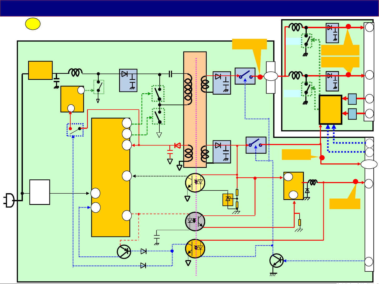
Start up Operation-12
< : LD board ( backlight drive ) >
6
Ex. 43/49DS630** series
( TNPA5916** )
( PFC = ON
AC100V: 380V
AC240V: 380V)
Q7301
Q7302
VCC
feedback
D7106
Rectifier
D7104,
7105
R7104-
7105
Q7202
Start Vcc
T7202
PFC
IC7201
8
VCC
7
Q7201
IC7301
VH
1
5
CS
(mode change)
D7215
C7213
HO
LO
VCC
REF
15
11
10
4
FB
6
PC7301
PC7303
T7301
D7401/02
C7422
D7408/09
C7423
IC7401
SRV-VLED
Q7402/05
24V/
32V(*)
16V
Q7403
8,9
P4
L7814
Q7804
L7813
Q7801
LD
SRV-16V
2
IC7503
6
CE
SRV-VLED1
SRV-VLED2
LED
Drive
IC7800
Vcc
BL-ON
PWM
16V
STB5V
SRV-5.3V
Anode1
Anode2
Cathode1
Tr
Cathode2
Tr
LD2
3
7
1
5
11
13
1 - 3
7
P
Q7303
PC7302
Standby/ON
L=ON
Switch
Q7401
(*)The DC level is different by the LCD panel.
P2
9
SUB-ON
39
Page 40
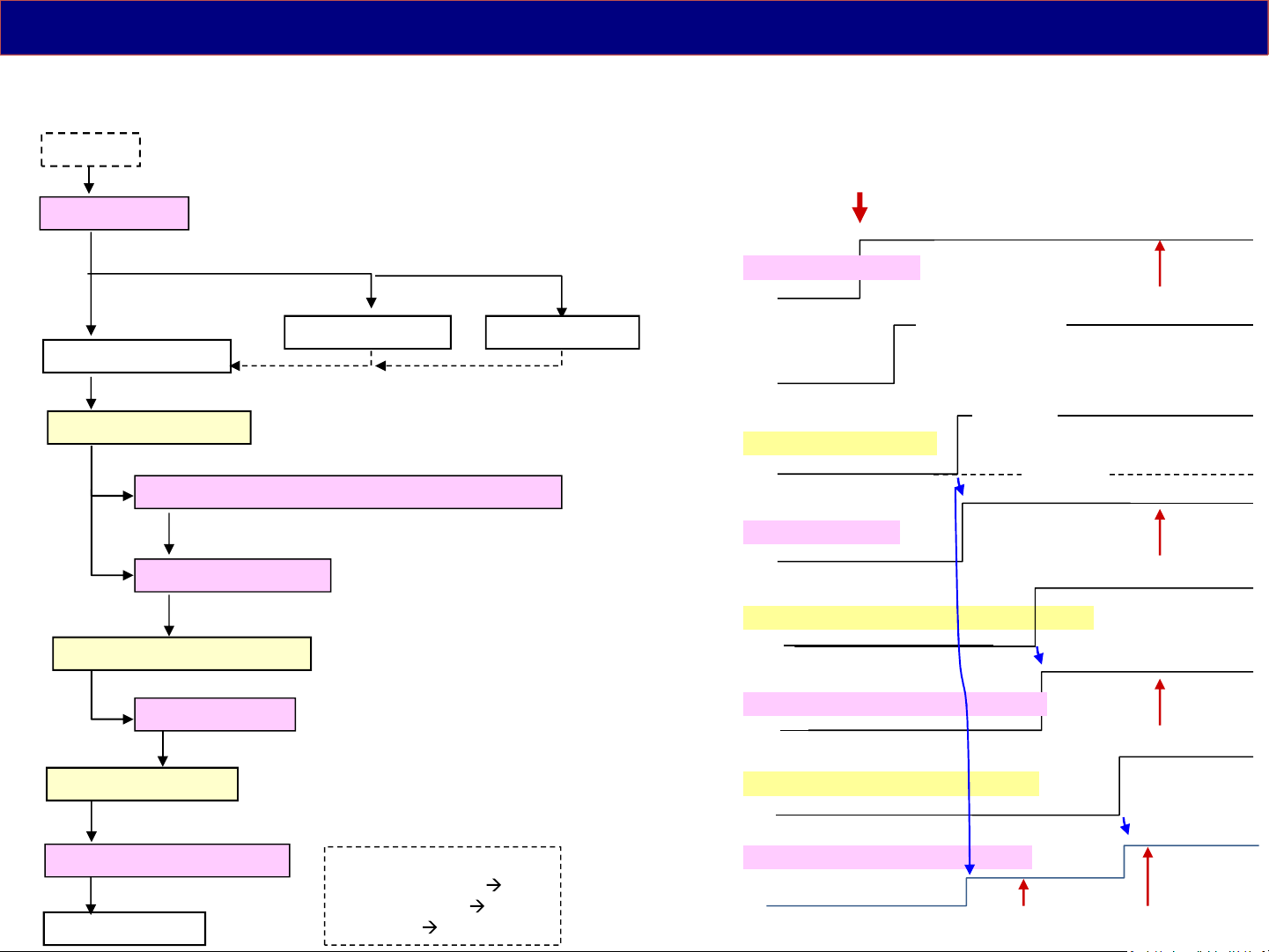
Simple Power On Sequence (D/DS Series)
< DS/D series >
( Plug in )
STB5V output
Power LED Green
TV_SUB_ON signal
PFC circuit ( IC7201/T7201 ) start working
16V / 32(*)V output
StandbyPower On
Power Off
Power LED Red Power LED off
Power SW on / Remote on
(*) The DC level is different by the LCD panel.
AC Plug in
STB5V (form P to A)
Standby / Power on
Power LED
Power on
SUB_ON (from A to P)
(Standby)
16V (from P to A)
5V
16V
PANEL_VCC_ON2 signal
PNL12V output
BL_ON_ON signal
16V / 32(*)V up to VLED
< Display start >
North America :
(Power LED Green RED)
(Power LED Red OFF)
(Power Off no exist)
Panel_Vcc_ON (from A to Panel(TCON))
PNL12V (from A to Panel(T-CON) )
BL_ON (from A to Panel(Backlight))
VLED (from P to Panel(Backlight) )
Ex.24V
12V
VLED
40
Page 41
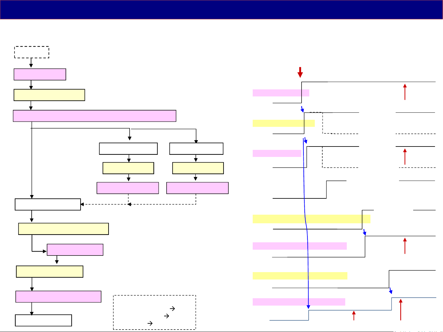
Simple Power On Sequence (DX Series)
< DX series >
Also 16V is necessary before Power LED on at first time.
( Plug in )
STB5V output
TV_SUB_ON signal
16V / 32(*)V output / PFC circuit start working
StandbyPower On
Power LED Red
TV_SUB_OFF TV_SUB_OFF
Stop 16V / 32(*)V
Power LED Green
Power SW on / Remote on
PANEL_VCC_ON2 signal
Power Off
Power LED off
Stop 16V / 32(*)V
(*) The DC level is different by the LCD panel.
AC Plug in
STB5V (form P to A)
Power on
SUB_ON (from A to P)
(Standby)
Power on
16V (from P to A)
(Standby)
Standby / Power on
Power LED
Power on
Panel_Vcc_ON (from A to Panel(TCON))
5V
16V
PNL12V output
BL_ON_ON signal
16V / 32(*)V up to VLED
< Display start >
North America :
(Power LED Green RED)
(Power LED Red OFF)
(Power Off no exist)
PNL12V (from A to Panel(T-CON) )
BL_ON (from A to Panel(Backlight))
VLED (from P to Panel(Backlight) )
12V
VLED
Ex.24V
41
Page 42
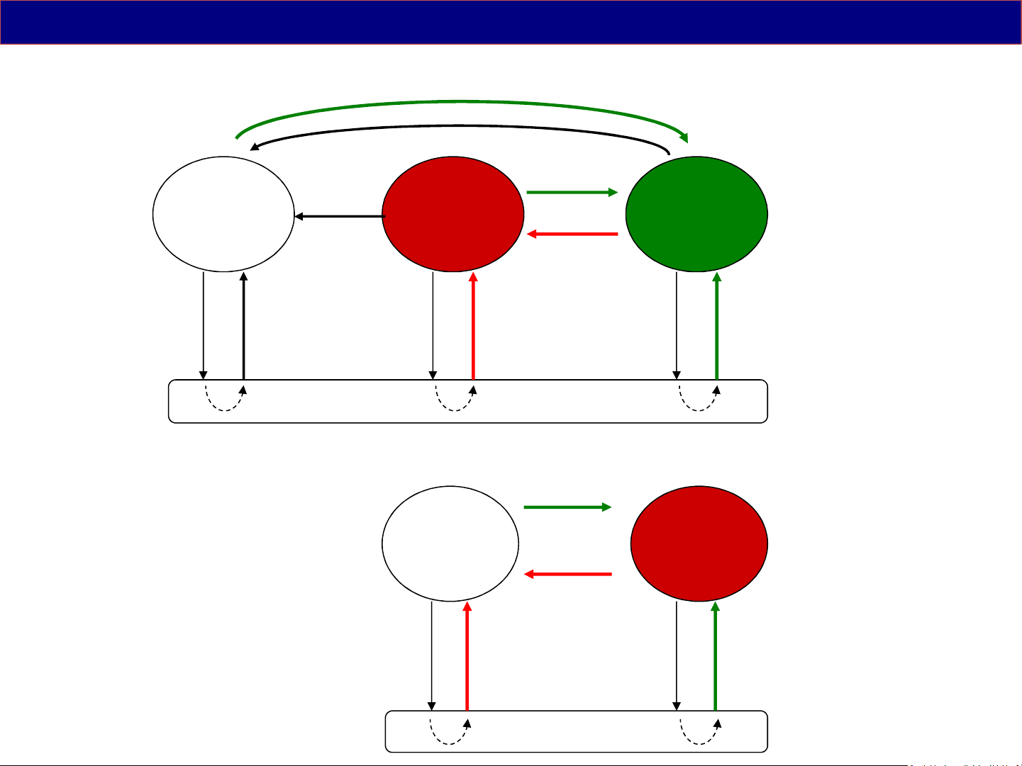
(Reference : State Transition Diagram)
< Except the Americas >
Pow-SW
Plug
Out
< The Americas >
Power Off
LED: OFF
Plug
In
Pow-SW
AC Off
Stand-by
LED: Red
Plug
Out
Stand-by
LED: OFF
Plug
In
Remote
Pow-SW /
Remote
Power On
LED: Green
Plug
Out
Power On
LED: Red
Plug
In
Plug
Out
Plug
In
AC Off
Plug
Out
Plug
In
42
Page 43

4. SOS Protection Circuit and Troubleshooting
(Except 1 time blink )
43
Page 44
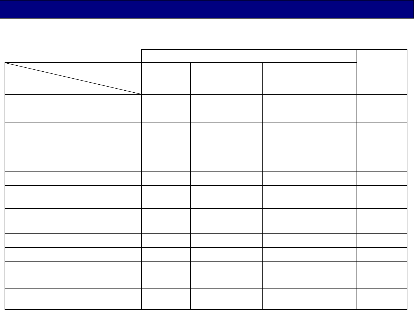
LED Blinking Summary
When an abnormality occurs in the unit, the “SOS Detect” circuit is triggered and the TV shuts down.
Shut down means that turn off the TV_SUB_ON signal. The power LED on the front panel will flash a
pattern indicating the circuit that has detected an abnormality.
Model name
(refer to the model
Detect content
lineup page)
BL_SOS (LED driver)
IROM SOS = Power on problem
(No F15V/SUB3.3V voltage)
IROM SOS = Power on problem
(No SUB5V/SUB1.5V/SUB1.1V voltage)
Memory (eMMC) read problem
No voltage SUB3.3V
(after wake up once)
Audio amplifier: SOUND_SOS
MT5561
(D** )
Blinking Time
Peaks LD6
Peaks
MT5810
(only
sLD8A
(DX**)
Euro DS6**)
(DS**/D**)
1
1
(occurred several sec
later after power on)
1 1
quick 1
(occurred soon
---
after power on)
quick 3 ---
quick 3
--- quick 5 --- ---
7 7 7 7
9 9 9 9
Estimated
Defect
Board
Panel/P
P/A
P/A
A
A
A/
Speaker
FRC_SOS (IC9000)
FAN_SOS
--- --- ---
--- --- ---
10
11
Back End SOS (inside of Peaks) --- 12 12 ---
Emergency SOS
GCEX_SOS (IC4300)
13 13 13 13
--- --- ---
16
A
Fan/A
A
A
A
44
Page 45
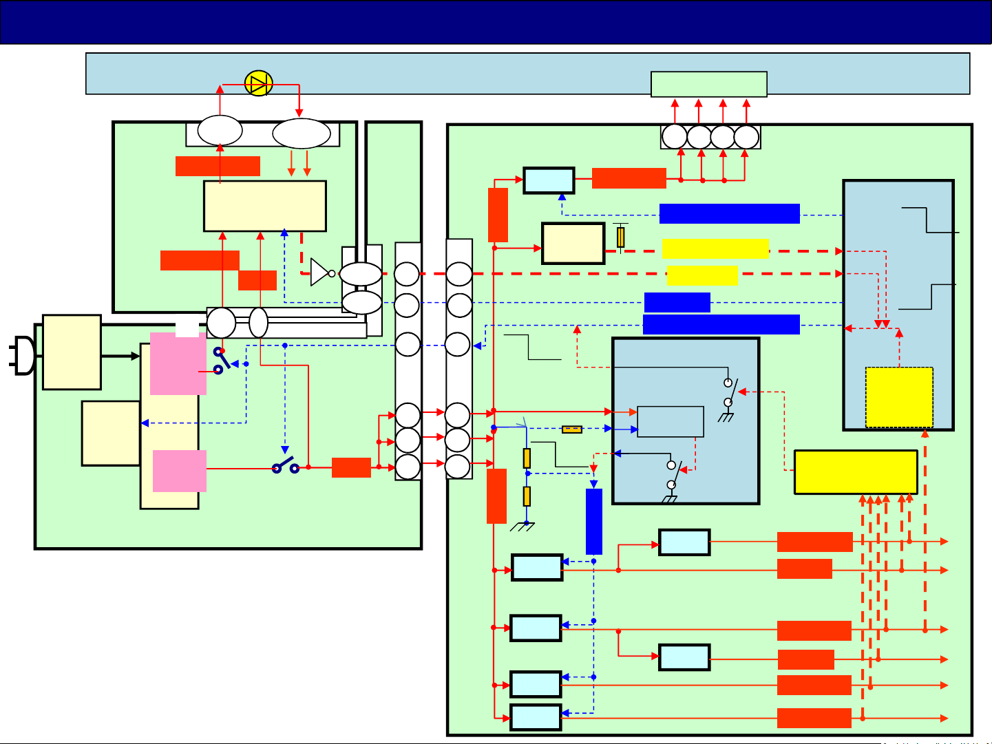
Protection Circuit
Back Light
3, 7
VLED1/2(*)
DCDC LED
LD1
8,9
P4
(*)
Q7402
/05
IC7800
16V
PFC
T7202
IC7201
DC/DC
IC7301
LD2
24/32V(*)
LD
24/32V
Output
Transformer
T7301
16V
Output
P
( TNPA5916** )
Ex. 43/49DS630** series
6
Q7403
1, 5
Drive
Back Light
Tr
3
16V
P2
11
LCD Module
IC5500
12V
PNL12V
T-CON
1
2 3 4
A19
IC8000
Panel_VCC_ON
F15V
84 14
10
9
2
ON OFF
IC4900
AMP
SOUND_SOS
BL_SOS
BL_ON
LCD_TV_SUB_ON
IC5000
(OFF)
(OFF)
Low
N SOS
9 Blink
1 Blink
N SOS
7 Blink
voltage
1
2
3
1
3
5
A02
N OFF
F15V
IC5420
5V
IC5400
DCDCEN
(OFF)
detect
3.3V
IC8001
IC5702
Over voltage
protection
HDMI3.3V
SUB5V
detect
(*)The DC level is different by the LCD panel.
3.3V
1.1V
1.5V
IC8100
IC8101
1.8V
IC5701/04
SUB3.3V
TU1.8V
SUB1.1V
SUB1.5V
A
45
Page 46
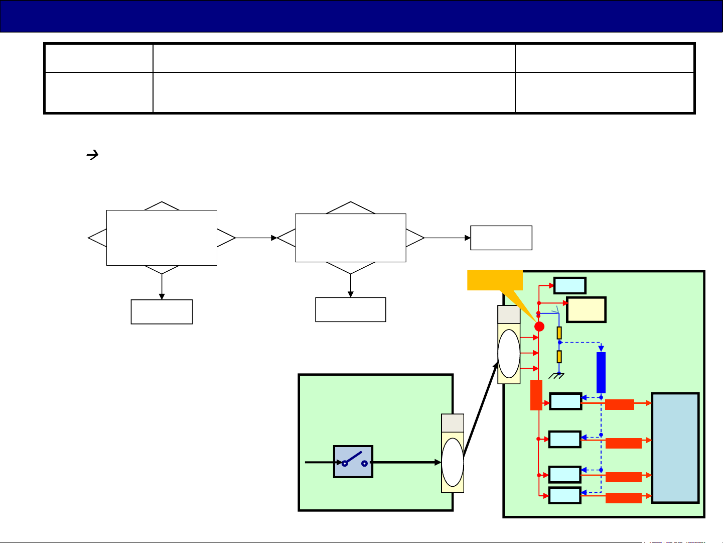
Troubleshooting for LED Blinking ( Quick 3 time blink )
LED blinks Detail error Board may defect
Quick 3 Power on problem
(No F15V/SUB3.3V/SUB1.5V voltage)
F15V(16V) is supplied from P board. If the F15V /SUB voltage is not supplied
LED blinks 3 times (quick blink).
Ex. 43/49DS630** series
Power on.
Check if voltage F15V at
pin 1,3,5 of A02
connector before LED
blinks?
Yes
(15V)
A board
No
Remove P2 connector.
Check if short-circuit at
pin 1,3,5 of A02
connector?
Yes
(Shorted)
A board
No
P board
SRV-16V
A02
1
3
5
12V
IC4900
P/A
IC5500
A
AMP
P
16V
Q7403
16V
P2
1
2
3
IC8716/5420
F15V
IC8705/5400
3.3V
IC8100
1.1V
1.5V
IC8101
DCDCEN
SUB5V
SUB3.3V
SUB1.1V
SUB1.5V
IC80005V
46
Page 47
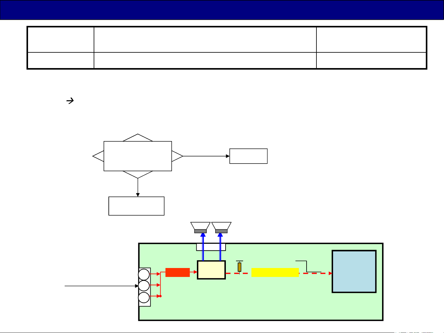
Troubleshooting for LED Blinking ( 9 time blink )
LED blinks Detail error Board may defect
9 Audio amplifier: SOUND_SOS A/Speaker
Audio amplifier is sourced power F15V from P board. If the amplifier work abnormally (may due
to short-circuit or overload), the SOUND_SOS signal will go low level and be detected by
IC8001 LED blinks 9 times.
Ex. 43/49DS630** series
Remove A12 connecter.
Power on.
Does LED blinks again?
No (Power on)
Yes
(9 time blinks)
A board
(wire of speaker)
16V
From P BOARD
L/R speaker
1
3
5
A02
A12
IC8000
IC4900
F15V SOUND_SOS 9 Blink
AMP
N SOS
A
47
Page 48
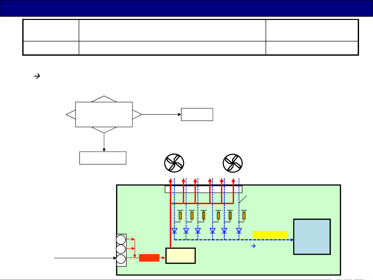
Troubleshooting for LED Blinking ( only DX900 : 11 time blink )
LED blinks Detail error Board may defect
11 Fan_SOS Fan/A
If one of the fan does not work, Fan_SOS signal will go high level and be detected by IC8001
LED blinks 11 times.
only DX9** series
Before shutdown,
are all fans stopped?
(only one fan is stopped)
Stopped fan
16V
From P BOARD
No
1
3
5
A02
Yes
(all stopped)
A08
Fan_Vcc
F15V
IC5901
DC/DC
A board
.. Fan x6 ..
( all fan output low signal Low )
(Low=Normal)
IC8000
Fan_SOS
11 Blink
= Normal
A
48
Page 49
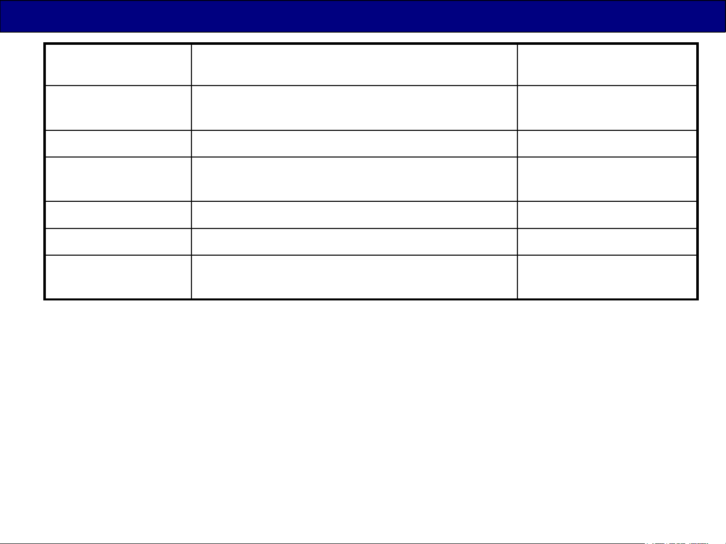
Troubleshooting for LED Blinking ( 5/7/10/12/13/16 time blink )
LED blinks Detail error Board may defect
5
(only Euro DS6** )
7 No voltage SUB3.3V detected A
10
(only DX*** series)
12
13 Emergency SOS A
16
(only DX9** series)
5 blinks is problem about memory access (IC8000 or IC8903)
7 blinks is problem about the power line of SUB3.3V.
10 blinks is problem about initialization of FRC IC (IC9000).
Memory (eMMC: IC8903) read problem
FRC_SOS (Initialization of IC9000)
Back End SOS (inside of Peaks)
GCEX_SOS (IC4300) A
A
A
A
12 and 13 blinks is problem about IC8000 and software item.
16 blinks is problem about initialization of GCEX IC (IC4300).
IN THIS CASE, A BOARD DEFECTS
49
Page 50
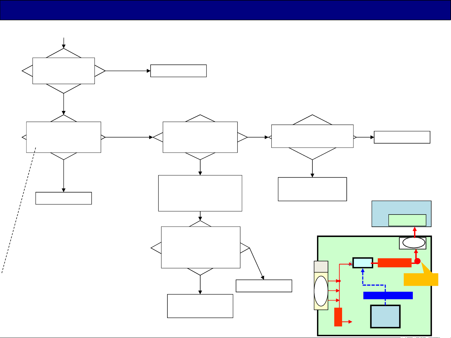
Troubleshooting for No Picture and No OSD (Power LED is lit = No blinking)
Refer to the block diagram “Troubleshooting for LED Blinking (1 time blink )”
Patterns are
Try the “LCD Panel
Test Mode”
No Picture
Is the power LED situation
changed after pushing the
button for entering Test
Mode?
displayed
Replace A board
LED blink (except TC- model)
LED off (TC- model)
Check if the Backlight is lit.
(open the back cover and
check from back side)
No lit
Check if voltage 24V/32V(*)
at SRV-LED in P board
No
Replace P board
No change
(LED keep lit)
Replace A board
If entering the test mode,
the Power LED will Blink(except TC- model)
or OFF (TC- model).
(*) The DC level is different by the LCD panel.
Lit
Confirm(Clean) the flat
cable connection
(between A board and T-CON
board of LCD Panel)
Disconnect A15/16/19
connecter(FFC cable to
Panel). Check if voltage
SRV-12V (PNL12V) in A
board
Yes
(12V)
Replace LCD Panel
(T-CON part)
No
Replace A board
Yes
24V/32V(*)
Replace LCD Panel
(Backlight part)
A
A02
1
3
5
F15V
LCD Module
A19
IC5300
12V
PNL12V
Panel_VCC_ON2
IC8000
T-CON
1-4
SRV-12V
50
Page 51
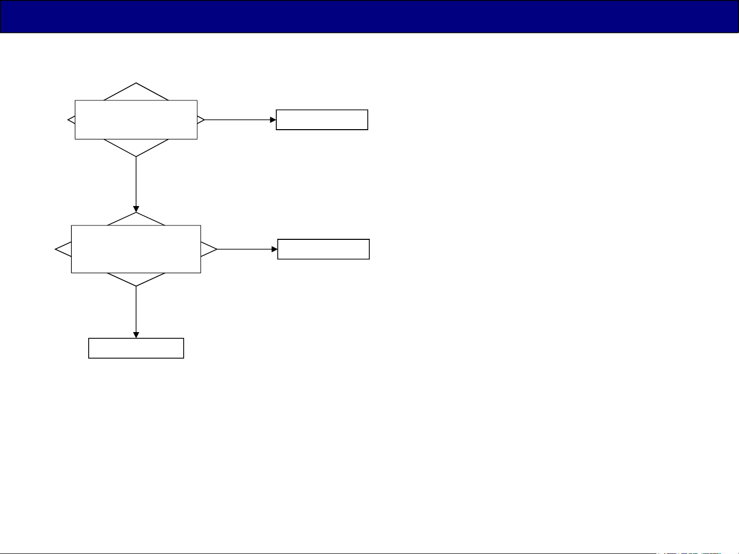
Troubleshooting for No Power On (Power LED is off = No blinking)
< DS/D series >
Check if the output of
STB5V.
NG
Disconnect A02 connecter.
Short check of STB5V line
in A board.
Shorted
Replace A board
Replace A board
OK
Replace P board
No
Shorted
51
Page 52
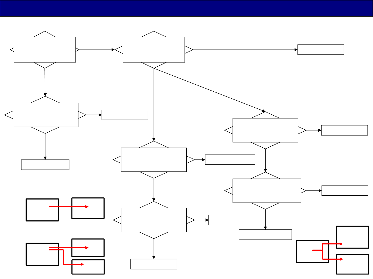
Troubleshooting for No Power On (Power LED is off = No blinking)
< DX series >
Check if the output of
STB5V.
NG
Disconnect A02 connecter.
Short check of STB5V line
in A board.
Shorted
Replace A board
DX9**
P2
P
16V
65DX8**/7**
P2
P
16V
A02
A02
PB4
DX series need both STB5V and 16V before lighting power LED. (Refer to Page41.)
OK
No
Shorted
A
A
PB
Check if the output 16V
(SRV-16V in A board)
Replace P board
(DX9** = skip to below )
Disconnect PB4 connecter.
Short check the SRV-16V
Disconnect A02 connecter.
Short check the SRV-16V
Replace A board
NG
(A+P+PB)
T*-65DX8**/7**
T*-**DX900/
TH-55DX640/
TC-55DX700
In A board.
Shorted
In A board.
Shorted
OK
(A+P, A+P+LDP)
T*-40,49,50DX***/
T*-58DX7**,DX8**/
TX-55DX***/
T*-55DX600,DX650
Replace PB board
No shorted
Replace P board
No shorted
Disconnect A02 connecter.
Short check the SRV-16V
In A board.
No shorted
(No LDP board = go to right)
Disconnect LDP3 connecter.
Short check the SRV-16V in
P board.
No shorted
Replace LDP board
Replace A board
Replace A board
Shorted
Replace P board
Shorted
P2
P
16V
P3
A02
LDP3
A
LDP
52
Page 53

5. SOS Protection Circuit and Troubleshooting
( 1 time blink )
53
Page 54
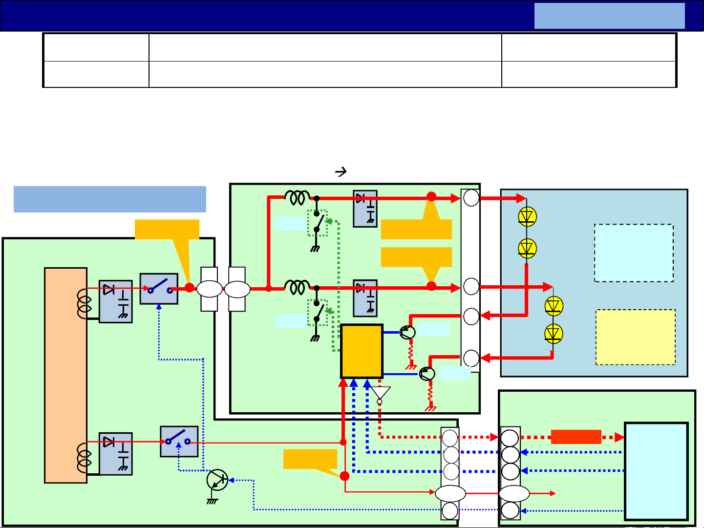
Troubleshooting for LED Blinking ( 1 time blink )
LED blinks Detail error Board may defect
1 BL_SOS (LED driver) Panel / LD / P
<A+P+LD/LDP> -1
If the IC7800 detects
(*)VLED : The DC level is different by the LCD panel.
1.abnormal current of backlight LEDs ( = Backlight LED broken or Low(No) VLED voltage )
2.abnormal DC/DC power supply of IC7800 (does not rise up the VLED voltage )
or the IC7800 does not work (No Vcc or No BL_ON/PWM signal or defect itself),
the IC7800 output BL_SOS signal to IC8001 LED blink 1 time.
Ex. 43/49DS630** series
SRV-VLED
T7301
D7401/02
C7422
D7408/09
24V/
32V(*)
C7423
Q7402/05
Q7403
16V
8,9
P4
Q7804
L7813
8,9
LD1
Q7801
LD
( TNPA5935** )
L7814
58V(*)
SRV-VLED1
SRV-VLED2
88V(*)
Q7802
LED
Drive
IC7800
Vcc
Tr
3
Anode1
Anode2
7
Cathode1
1
Cathode2
5
Q7803
LD2
P2
14
A02
8
LCD Module
Back
light
(Low=Normal)
BL_SOS
LCD Panel
T-CON
board
A
P
( TNPA5916** )
Q7401
SRV-16V
SUB-ON
16V
BL-ON
PWM
11
13
1 - 3 1,3,5
9
12
10
2
BL-ON
PWM
SUB-ON
IC8000
PEAKS
Page 55
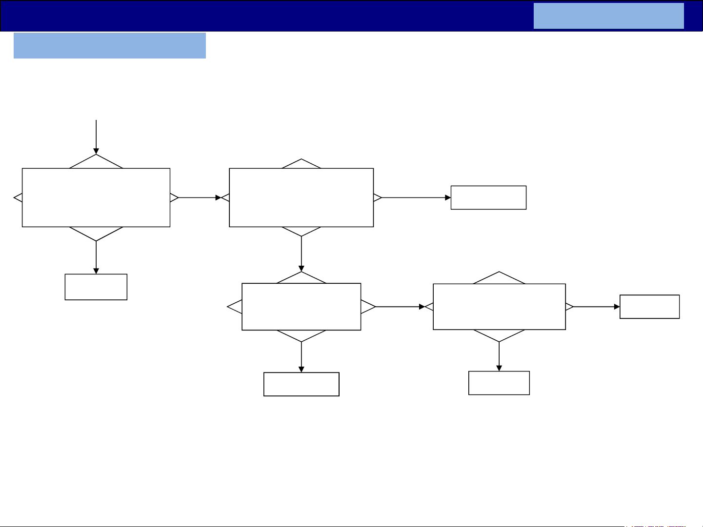
Troubleshooting for LED Blinking ( 1 time blink )
Ex. 43/49DS630** series
Refer to the previous page block diagram.
<A+P+LD/LDP> -2
(Power off)
Disconnect LD1 and LD2
connectors. Short check between
pin8,9 of LD1 and GND,
pin1,5 of LD2 and GND.
NG
LD board
ALL OK
Connect LD1 and LD2
connectors. Power on.
Check if the voltage
of SRV-VLED1, VLED2 (pin 3 , 7
of LD2) before LED 1 blink?
NG
Short check between SRV-
VLED1, VLED2 and GND
Shorted
Panel Module
Both OK
58V(*),
88V(*)
OK
Panel Module
Power on.
Check if the voltage
of SRV-VLED (pin 9 of LD1)
before LED 1 blink?
NG
P board
OK
32V(*)
LD board
(*)VLED : The DC level is different by the LCD panel.
55
Page 56
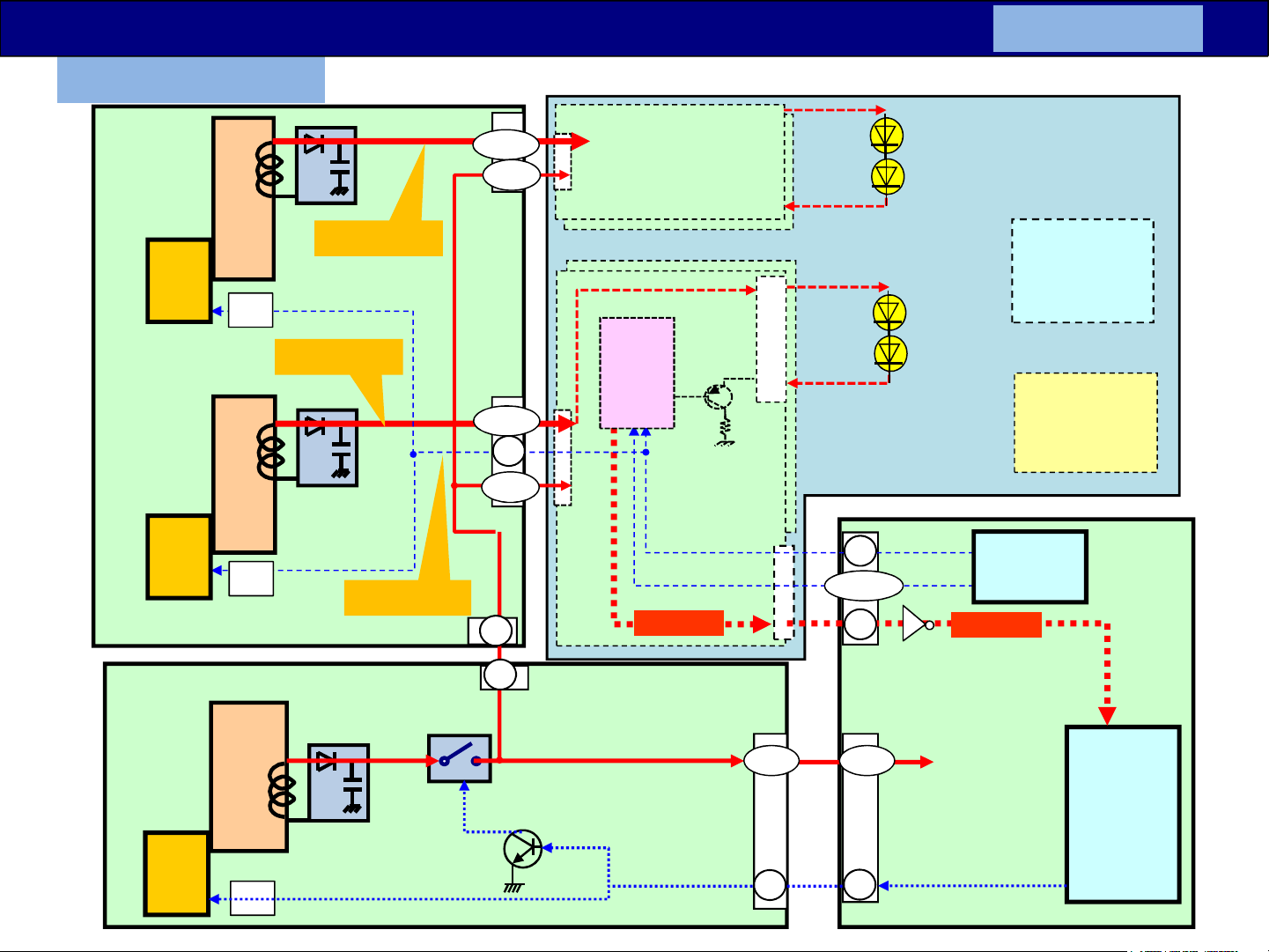
Troubleshooting for LED Blinking ( 1 time blink )
(*)VLED : The DC level is
different
by the
LCD panel.
Ex. DX900** series
VLED2
17-28
PB
9,10
PB2
SRV-VLED2
<A+P+PB> -1
LCD Module
Back
Power
IC
Power
IC
(TNPA6200)
(TNPA6199)
P
Photo
coupler
SRV-VLED1
Photo
coupler
VLED1
BL-ON
SRV-BL-ON
PB3
16V
P3
PB1
17-28
5
9,10
1
1
LED
Drive
IC
Sync/control/…
BL_SOS
16V
P2
1 - 5
Anode
Cathode
2,4,6,,,
15
1
A03
A02
1 - 5
light
BL-ON
Tr
LCD Panel
T-CON
IC9000
FRC
BL_SOS
(Low=Normal)
board
A
IC8000
Power
IC
Photo
coupler
SUB-ON
11
MTK
11
SUB-ON
56
Page 57
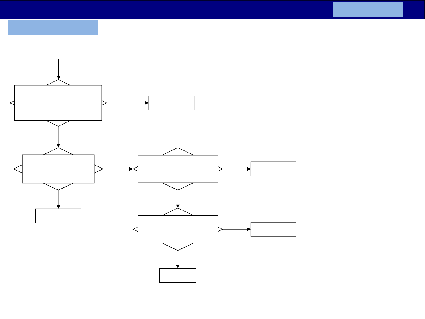
Troubleshooting for LED Blinking ( 1 time blink )
Ex. DX900** series
Refer to the previous page block diagram.
Power on.
Check if the voltage
of SRV-VLED1(pin17-28 of PB1)
and SRV-VLED2 (pin17-28 of
PB2) before LED 1 blink?
NG
Both OK
58V(*),
88V(*)
Panel Module
<A+P+PB> -2
(Power off) Disconnect
PB1 and PB2 connector.
Short check between SRV-
VLED1, VLED2 and GND
Shorted
PB Module
(*)VLED : The DC level is different by the LCD panel.
OK
Check if the voltage
of SRV-BL-ON (pin 5 of PB1)
before LED 1 blink?
NG
Check if the voltage
of BL_ON (pin 15 of A03)
before LED 1 blink?
NG
A board
OK
3.3V
OK
3.3V
Panel Module
Panel Module
57
Page 58
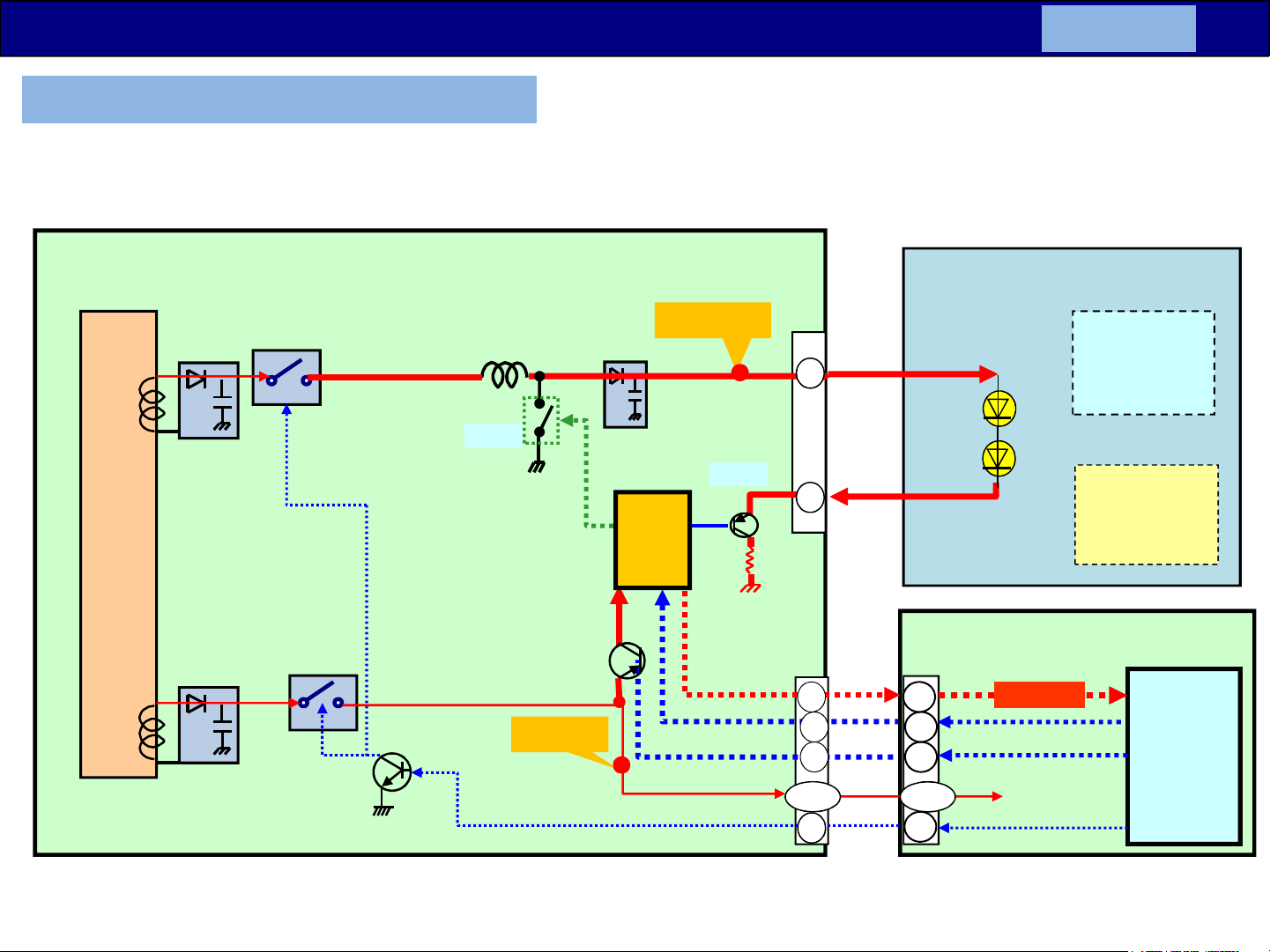
Troubleshooting for LED Blinking ( 1 time blink )
Ex. 32D400/410, 32DS500/600 series
<A+P> -1
P
T7301
( TNP4G572** )
D7507/08
C7502
D7502
C7512
Q7501
16V
Q7502
Q7510
24/32V(*)
L7801
Q7801
Vcc
SRV-16V
SRV-VLED
70V(*)
LED
Drive
IC7800
16V
SUB-ON
P3
Q7803
P2
(Low=Normal)
PWM
BL-ON
Anode
3
Cathode
1
11
13
12
1,2,3
8
A02
8
12
10
1,3,5
2
Back
light
(Low=Normal)
BL_SOS
PWM
BL-ON
SUB-ON
LCD Module
LCD Panel
T-CON
board
A
IC8000
PEAKS
(*)VLED : The DC level is different by the LCD panel.
58
Page 59
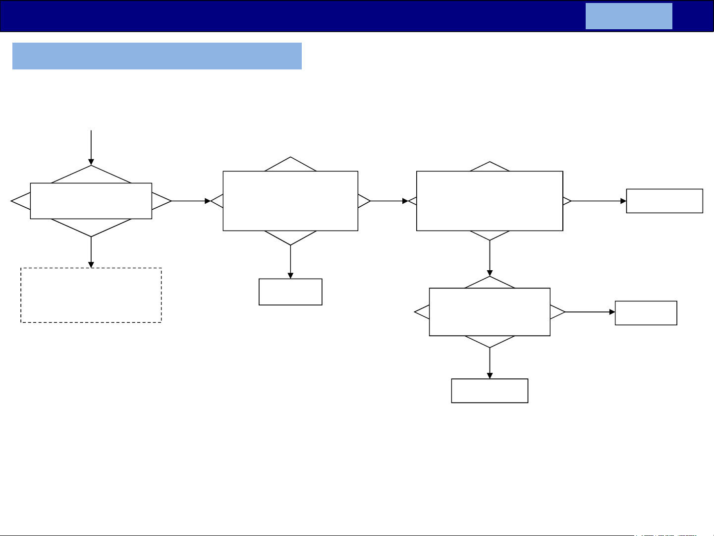
Troubleshooting for LED Blinking ( 1 time blink )
Ex. 32D400/410, 32DS500/600 series
<A+P> -2
Does the blinking start
soon after power on?
Yes
(#Euro DS6** model only)
Go to troubleshoot of
quick 3 time blink page
(check with that procedure)
No
(after
several
sec.)
(Power off)
Disconnect P3 connectors.
Short check between
pin1,3 of P3 and GND.
Short
P board
Both
OK
Connect P3 connector.
Power on.
Check if the voltage
of SRV-VLED(pin 3 of P3)
before LED 1 blink?
NG
Short check between SRV-
VLED and GND
Shorted
Panel Module
OK
Panel Module
70V(*)
P board
OK
(*)VLED : The DC level is different by the LCD panel.
59
Page 60
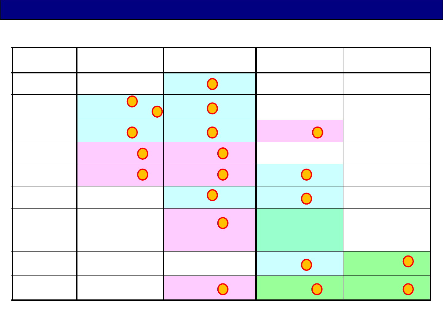
Backlight Drive Structure -1
24inch
32inch
40inch
43inch
49inch
50inch
55inch
D4** DS4**/5**/6** DX6**/7**/8**
(4K)
--- A+P --- ---
A+P /
(India : 1 Board)
A+P A+P A+P+LDP ---
A+P+LD A+P+LD --- ---
1
1 1
2
A+P --- ---
4
A+P+LD A+P+LD A+P ---
--- A+P A+P ---
1
1
2
2
22
1
1
1
--- A+P+LDP A+P ,
2
A+P+PB: (only
TH-55DX640*,
TC-55DX700*)
DX900
(4K)
---
58inch --- --- A+P A+P+PB
1
65inch
--- A+P+LDP A+P+PB A+P+PB
2
Except K, GK boards
3
33
60
Page 61
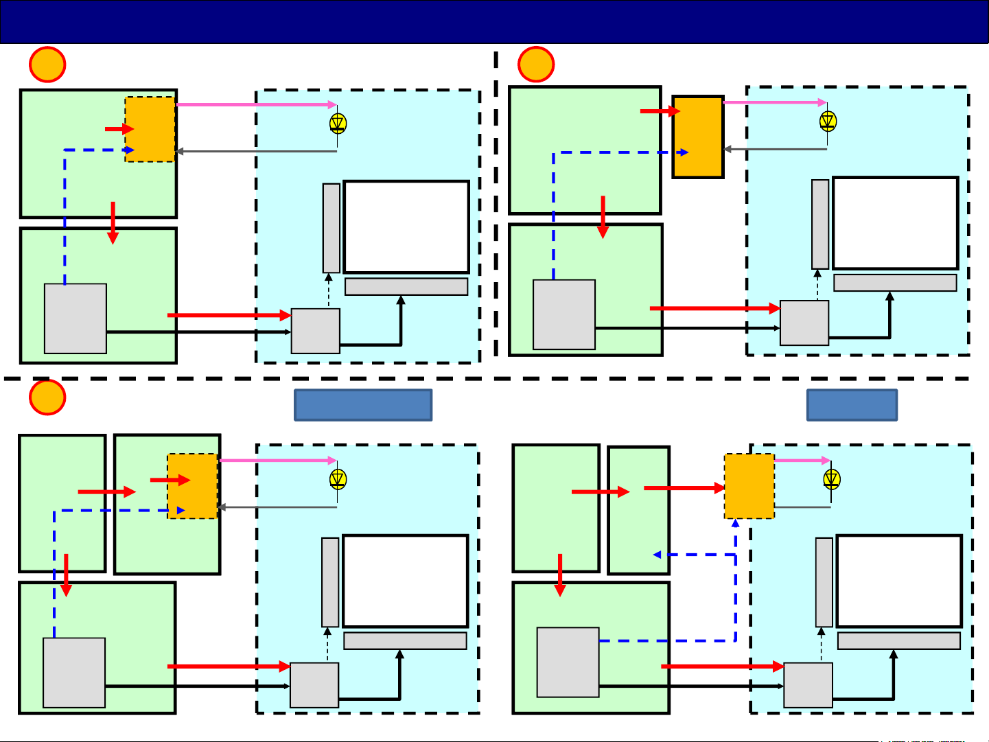
Backlight Drive Structure -2
1
< 1. A+P >
VLED(*)
P
24/32V(*)
LED
Drive
BL_ON
16V, STB5V
A
IC8000
(Peaks/MTK )
Resize
IP conv.
3
< 1. A+P+PB board >
P
390V
PB
24/32V(*)
BL_ON
PNL12V
LED
Drive
VLED(*)
LCD Panel Module
Backlight
Dr
T-CON
LCD Panel
Dr
(DX6**/7**)
LCD Panel Module
Backlight
2
< 2. A+P+LDP/LD >
P
24/32V(*)
BL_ON
LD/
LDP
LED
Drive
16V, STB5V
A
IC8000
(Peaks/MTK )
Resize
IP conv.
P
390V
PB
PNL12V
VLED1/2
VLED(*)
LED
Drive
LCD Panel Module
Backlight
Dr
T-CON
LCD Panel
Dr
(DX900)
LCD Panel Module
Backlight
16V, STB5V
A
IC8000
(Peaks/MTK )
Resize
IP conv.
PNL12V
Dr
LCD Panel
16V, STB5V
A
BL_ON
T-CON
Dr
IC8000
(Peaks/MTK )
Resize
IP conv.
(*)The DC level is different by the LCD panel.
PNL12V
T-CON
Dr
LCD Panel
Dr
61
 Loading...