

Page 1
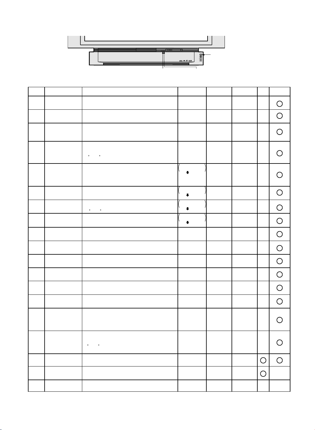
LED INDICATIONS FOR ERROR CONDITION
Each LED indication facilitates finding the cause of the error.
When an error is detected, each LED on the front will light up or flash when the AC Cord is plugged in.
The detected error data will not be stored in the EEPROM. This data is cleared when the AC Cord is unplugged.
POWER LED
TEMP LED
LAMP LED
(Note 3) (Note 4)
Error InformationError No. ERROR DESCRIPTION LAMP OFFLAMP LED
Fan1, Fan2 or Fan3
1)
stopped
Lamp Cover open
2)
Temperature Sensor
3)
shorted or open
Abnormal
4)
Temperature
Ballast Error
5)
(abnormal Lamp)
Ballast Error
6)
(abnormal
Lamp voltage)
Ballast Error
7)
(abnormal
temperature)
Ballast Error
8)
(other causes)
Abnormal Voltage
9)
on 33 V line of
Main C.B.A.
10)
Abnormal Voltage
on 9 V line of
Main C.B.A.
Abnormal Voltage
11)
on 5 V line of
Main C.B.A.
Abnormal Voltage
12)
on 3.3 V line of
Main C.B.A.
Abnormal Voltage
13)
on -5 V line of
Main C.B.A.
Abnormal Voltage
14)
on 6.5 V line of
Main C.B.A.
Temperature Sensor
15)
shorted or open
16)
Abnormal
Temperature
Clogged air filter
17)
18)
Request for Lamp
Replacement
-
Forced cooling
Note:
1.When any of the above errors has occurred, the LED will flash as shown above.
2.When two or more errors have occurred at the same time, the LED will alternate light up and/or flash patterns as shown
above every 5 seconds.
3.Warning OSD appears when the air filter is clogged or accumulated Lamp operation time reaches 10,000 hours.
4.LAMP OFF: The LED will flash immediately after the Lamp comes off.
5.IC6003 and IC6302 are mounted on the Main C.B.A.
IC6302(pin6) detects the stop of FAN1, FAN2 or FAN3,
then indicates the error when the FAN1, FAN2 or FAN3 is
stopped.
IC6003(pin66) detects the Lamp Cover condition
(open or close), then indicates the error when the Lamp Cover
is open.
IC6302(pin4 and 5) detects open or short of the Temperature
Sensor (R2811) on Thermistor 1 C.B.A., then indicates the
error when Temperature Sensor is open or shorted.
(The error is not detected for 1 minute after Lamp ON.)
IC6302(pin4 and 5) detects the temperature near
the FAN1 by the Temperature Sensor (R2811) on Thermistor 1
C.B.A., then indicates the error when the temperature exceeds
55 C (131 F).
(The error is not detected for 1 minute after Lamp ON.)
IC6003(pin19) detects the error of the Lamp, and Ballast C.B.A.,
then indicates the error when an inner malfunction of Ballast
C.B.A. occurs, the Lamp voltage becomes more than 130V or
less than 30V, the Lamp is cracked, the Thermal Fuse Unit is
open or the Lamp is not cooled off.
IC6003(pin19) detects the error of the Lamp, then indicates the
error when the Lamp is defective.
IC6003(pin19) detects the error of Ballast C.B.A.,
then indicates the error when the thermal fuse (F1302)
117 C (243 F) in Ballast C.B.A. is open.
IC6003(pin19)
then indicates the error when an inner malfunction of Ballast
C.B.A. occurs.
IC6302(pin61) detects +33V line voltage on Main C.B.A., then
indicates the error when the voltage becomes less than +10V.
IC6302(pin64) detects +9V line voltage on Main C.B.A., then
indicates the error when the voltage becomes less than +2V.
IC6302(pin63) detects +5V line voltage on Main C.B.A., then
indicates the error when the voltage becomes less than +1V.
IC6302(pin7) detects +3.3V line voltage on Main C.B.A., then
indicates the error when the voltage becomes less than +1.5V.
IC6302(pin62) detects -5V line voltage on Main C.B.A., then
indicates the error when the voltage becomes more than 0V.
IC6302(pin60) detects +6.5V line voltage on Main C.B.A., then
indicates the error when the voltage becomes less than +2V.
IC6302(pin2 and 3) detects open or short of the
Temperature Sensor (R2821) on Thermistor 2 C.B.A.,
then indicates the error when Temperature Sensor is open or
shorted.
(The error is not detected for 4 minutes after Lamp ON.)
IC6302(pin2 and 3) detects the temperature near
the Lamp by the Temperature Sensor (R2821) on Thermistor 2
C.B.A., then indicates the error when the temperature exceeds
85 C (185 F).
(The error is not detected for 4 minutes after Lamp ON.)
IC6003(pin65) detects clogged air filter when the filter detection
value exceeds the standard value.
When accumulated Lamp operation time reaches 10,000
hours, OSD (replacing the Lamp) appears on the screen.
Note: The Lamp time is stored in EEPROM (IC6005).
Indicated during forced cooling.
detects the error of Ballast C.B.A.,
flashes orange
once every
5 seconds
flashes orange
twice every
5 seconds
-
-
flashes green for
140 seconds.
flashes red
flashes green for
140 seconds.
flashes red
flashes green for
140 seconds.
flashes red
flashes green for
140 seconds.
flashes red
flashes orange
5 times every
5 seconds
flashes orange
6 times every
5 seconds
flashes orange
7 times every
5 seconds
flashes orange
8 times every
5 seconds
flashes orange
9 times every
5 seconds
flashes orange
10 times every
5 seconds
-
-
-
flashes red for
10 minutes
TEMP LEDPOWER LED
--
-
flashes once
every 5 seconds
flashes twice
every 5 seconds
-
-
-
-
flashes once
every 5 seconds
flashes twice
every 5 seconds
flashes 3 times
every 5 seconds
flashes 4 times
every 5 seconds
flashes 5 times
every 5 seconds
flashes 6 times
every 5 seconds
flashes 3 times
every 5 seconds
flashes 4 times
every 5 seconds
flashes 5 times
every 5 seconds
-
-
-
-
-
flashes once
every 5 seconds
flashes twice
every 5 seconds
flashes 3 times
every 5 seconds
flashes 4 times
every 5 seconds
flashes once
every 5 seconds
flashes twice
every 5 seconds
flashes 3 times
every 5 seconds
flashes 4 times
every 5 seconds
flashes 5 times
every 5 seconds
flashes 6 times
every 5 seconds
-
-
--
lights up
flashes 5 times
every 5 seconds
OSD
Page 2
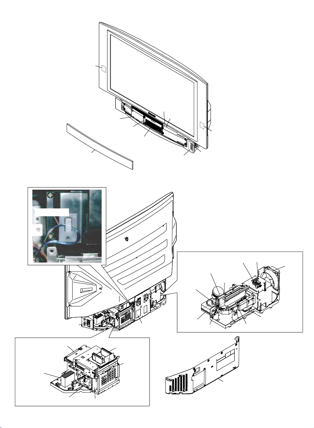
MAIN PARTS LOCATION
Network C.B.A.
<Front View>
Lamp Cover
Cover Switch C.B.A.
Optical Cover
TEMP LED
LAMP LED
Network C.B.A.
Front Cover Unit
20-pin Cable
Front Jack C.B.A.
Operation C.B.A.
<Rear View>
Ballast C.B.A.
POWER LED
Projection Unit
Thermal Fuse Unit
Thermistor 1 C.B.A.
Air Filter
Fan Case Unit
(Fan 1)
Air Filter
Air Filter
Thermistor 2 C.B.A.
Fan 3
Fan 2
LCD Drive C.B.A.
Audio
Amp C.B.A.
Main C.B.A.
Power C.B.A.
Tuner C.B.A.
Fan 4
Rear Cover
Rear Jack C.B.A.
TV/Tuner Unit
Page 3
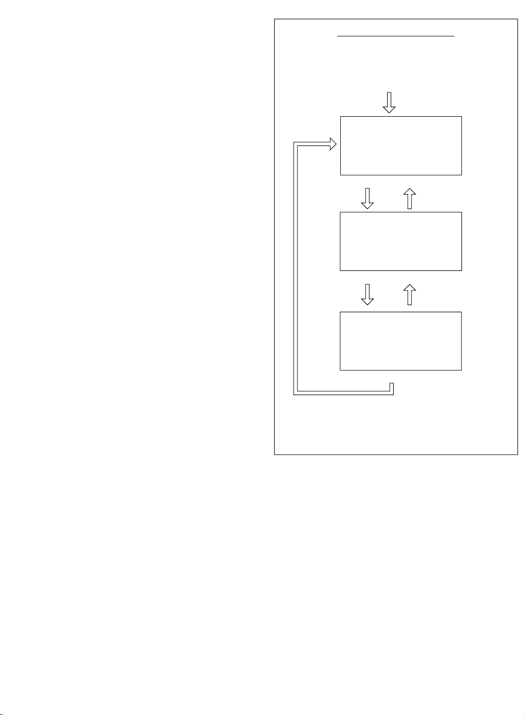
Service Mode Map
CH DOWN key CH UP key
CH DOWN key
CH DOWN key
CH UP key
Enter :
VOLUME DOWN button + TV/VIDEO key
(on the front) (on the remote)
(for more than 5 seconds in power off condition)
Exit:
Power OFF.
(When turning the power on again after once turning
off, wait for approx. 10 seconds. Or, the unit can not be
released from Service Mode.)
< Service Mode (2/3) >
< Service Mode (3/3) >
< Service Mode (1/3) >
SERVICE MODE 1/3
LAMP OPERATION TIME
TOTAL : 12345h
CURRENT LAMP: 2000h
OSD DISPLAY : ON
LON COUNT : 153
Power ON
SERVICE MODE P6:11010101 3/3
IC6003 PORT P3:00000000
P0:11001101 P4:11010101
P1:10001101 P5:10000111
P2:11001101 P7:10000111
IC6302 PORT P8:11010101
P0:001-1111 P5:-----000
P1:-0-0-0-1 P6:11011001
P2:---00111 P7:11100000
P3:00000111 P8:----0111
P4:11110011 PA:----1111
SERVICE MODE 2/3
IR:1 UNIT:1
IC3501:1 3601:1 3602:1
5005:1 5009:1 5504:1
6005:1 6006:1 7501:1
IC5302:1 5306:1 6501:1
9004:1 E:030630
F:0305000
IC6003 V:0307080
IC6302 V:0307010
SERVICE MODE
In this mode, the following information can be confirmed on the
screen:
Service Mode (1/3)
• Total Lamp elapsed time
• Current Lamp elapsed time
• The number of Lamp ON (For reference only)
Service Mode (2/3)
• Key detection check
• Communication check for IIC bus on the Main C.B.A.
• Communication check for serial bus on the Main C.B.A.
• EEPROM IC6006 version and build version
• EEPROM IC6306 version and build version
• IC6003 software version and build version
• IC6302 software version and build version
(For reference only)
(For reference only)
(For reference only)
(For reference only)
Service Mode (3/3)
• IC6003 Port information
• IC6302 Port information
Note:
IC6003: Main Microcontroller on the Main C.B.A.
IC6302: Sub Microcontroller on the Main C.B.A.
Fig. 1-1
Page 4
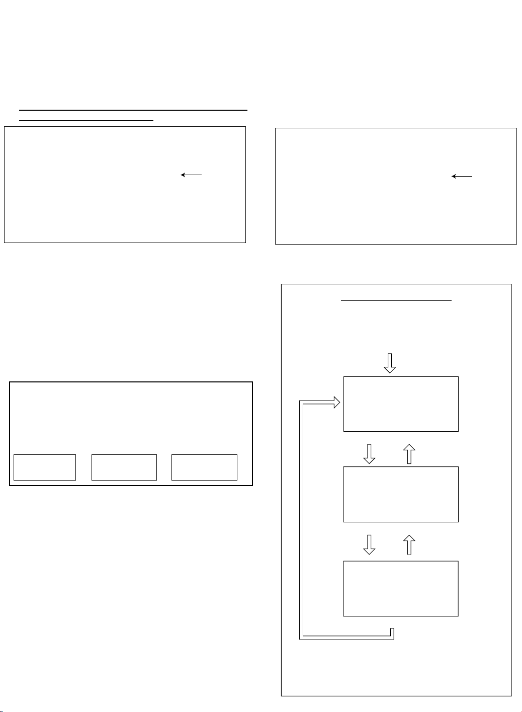
BEFORE REMOVING THE MAIN C.B.A. OR
Value A
(Changeable)
<Service Mode (1/3)>
SERVICE MODE 1/3
LAMP OPERATION TIME
TOTAL : 12345h
CURRENT LAMP: 2000h
OSD DISPLAY : ON
LON COUNT : 153
Service Mode Map
CH DOWN key CH UP key
CH DOWN key
CH DOWN key
CH UP key
Enter :
VOLUME DOWN button + TV/VIDEO key
(on the front) (on the remote)
(for more than 5 seconds in power off condition)
Exit:
Power OFF.
(When turning the power on again after once turning
off, wait for approx. 10 seconds. Or, the unit can not be
released from Service Mode.)
< Service Mode (2/3) >
< Service Mode (3/3) >
< Service Mode (1/3) >
SERVICE MODE 1/3
LAMP OPERATION TIME
TOTAL : 12345h
CURRENT LAMP: 2000h
OSD DISPLAY : ON
LON COUNT : 153
Power ON
SERVICE MODE P6:11010101 3/3
IC6003 PORT P3:00000000
P0:11001101 P4:11010101
P1:10001101 P5:10000111
P2:11001101 P7:10000111
IC6302 PORT P8:11010101
P0:001-1111 P5:-----000
P1:-0-0-0-1 P6:11011001
P2:---00111 P7:11100000
P3:00000111 P8:----0111
P4:11110011 PA:----1111
SERVICE MODE 2/3
IR:1 UNIT:1
IC3501:1 3601:1 3602:1
5005:1 5009:1 5504:1
6005:1 6006:1 7501:1
IC5302:1 5306:1 6501:1
9004:1 E:030630
F:0305000
IC6003 V:0307080
IC6302 V:0307010
THE TV/TUNER UNIT FROM THE UNIT AT
THE USER’S LOCATION
Note:
The TV/Tuner Unit includes the Main C.B.A.
CAUTION:
Be sure to make a note of the CURRENT LAMP value
1.
(value A) in Service Mode (1/3):
SERVICE MODE 1/3
LAMP OPERATION TIME
TOTAL : 12345h
CURRENT LAMP: 2000h
OSD DISPLAY : ON
LON COUNT : 153
<Service Mode (1/3)>
Value A
(Changeable)
WHEN REINSTALLING THE MAIN C.B.A.
OR THE TV/TUNER UNIT INTO THE UNIT
AT THE USER’S LOCATION
CAUTION:
1. Set CURRENT LAMP value to original value as follows.
1) Select CURRENT LAMP in Service Mode (1/3).
2) Press the VOLUME UP/DOWN key on the remote to
change to the original value (value A) that was noted
before removing the Main C.B.A. or the TV/Tuner Unit
at the user’s location.
Fig. 2
LAMP OPERATION TIME is stored in EEPROM on the
Main C.B.A. Therefore, before removing the Main C.B.A. or
the TV/Tuner Unit at the user’s location, make a note of the
CURRENT LAMP value (value A) in Service Mode (1/3).
Then, after installing the new Main C.B.A. or the TV/Tuner
Unit at the user’s location, set the CURRENT LAMP value
to the original value (value A) in Service Mode.
Otherwise, OSD and LED Lamp replacement indications
will be displayed at the wrong time.
Note:
In case it is impossible to make a note of the CURRENT
LAMP value because of a defective Main C.B.A., ask the
customer their daily average use and the approximate age
of the current Lamp. Then, calculate the CURRENT LAMP
value as follows and make a note.
Daily average use
(hours) (days) (hours)
Note:
The TOTAL value can be set to the original value in Service
Mode (1/3) by similar method:
Before removing the Main C.B.A. at the user’s location,
make a note of the TOTAL value in Service Mode (1/3).
Approx. age CURRENT LAMP
X=
Then, after installing the new Main C.B.A. at the user’s
location, set the TOTAL value to the original value in
Service Mode.
Fig. 3
Page 5
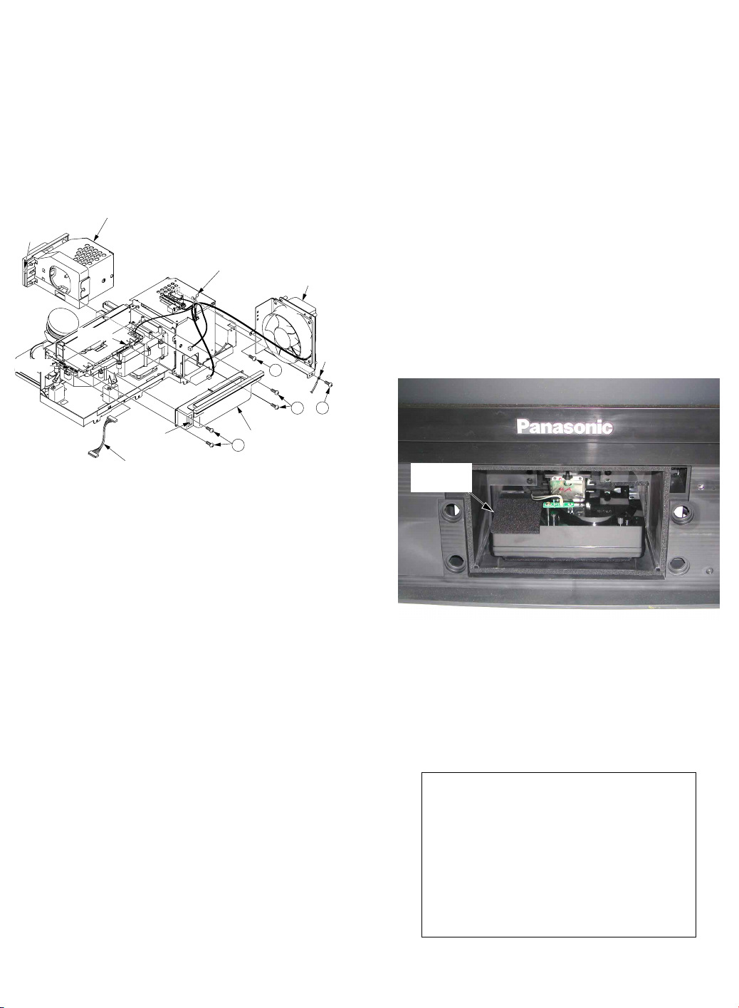
BEFORE REMOVING THE PROJECTION
Projection
Unit
<Front View>
(With Front Cover Unit and Optical Cover removed)
C-COR/GAM/W-BAL
PUSH RECALL 5SEC
WORK MODE
<Work Mode>
UNIT FROM THE UNIT AT THE USER’S
LOCATION
WHEN REINSTALLING THE PROJECTION
UNIT INTO THE UNIT AT THE USER’S
LOCATION
1. When removing the Projection Unit, remove the Lamp from
the Projection Unit and keep it. Then, reinstall this Lamp
into the new Projection Unit.
2. When removing the Projection Unit, remove the Fan 3 Unit,
the Top Duct 3 Unit and the 20-pin Cable from the Projection
Unit and keep them. Then, reinstall the Fan 3 Unit, the Top
Duct 3 Unit and the 20-pin Cable into the new Projection
Unit.
Screw
for lamp
P2501
Lamp
P2904
Clamper
20-pin Cable
Clamper
Top Duct 3 Unit
421
Fan 3 Unit
402
421
GND
Wire
402
Fig. 4-1
1. Be sure to install the original Lamp, the Fan 3 Unit, the Top
Duct 3 Unit and the 20-pin Cable into the new Projection
Unit.
CAUTION:
Confirm that there is no dust on the Top Duct 3 Unit before
installing. If there is dust, clean the Top Duct 3 Unit with a
brush, etc. Otherwise, dust may adhere to the inside of the
screen.
2. The following ADJUSTMENT of the Projection Unit must be
performed.
a. Mechanical Picture Position Adjustment
b. Focus Adjustment
Note:
Perform this adjustment only if necessary. (Normally, it
will not be necessary.)
c. Electrical Picture Position Adjustment
Preparation of ADJUSTMENT:
1. Install all parts except the Front Cover Unit and the Optical
Cover.
Fig. 4-2
2. Turn the power on.
3. Press and hold the VOLUME DOWN button on the unit and
the RECALL key on the remote for more than 5 seconds in
power on condition. The unit will go into Work Mode.
(“WORK MODE” will appear on the screen.)
Fig. 4-3
Page 6
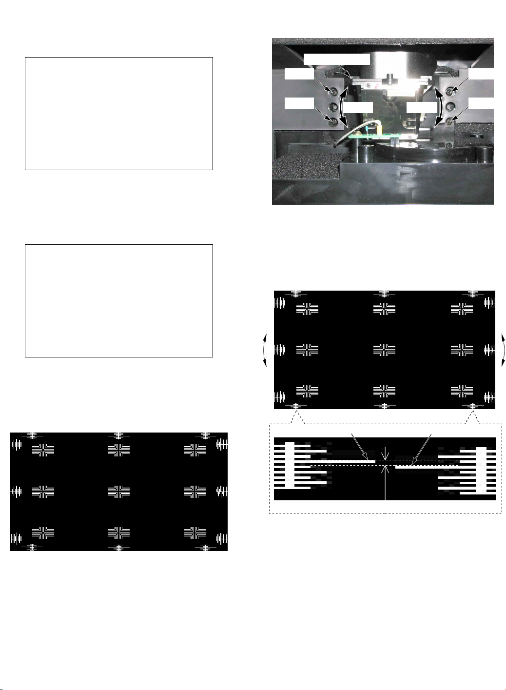
4. 1) Then, press and hold the VOLUME DOWN button on
Screw
Projection Lens
Twist Twist
Screw
Screw
Screw
<Front View>
OPT HPOSI 16
OPT VPOSI FE
<Focus Screen>
"G" "H"
within 4 dots
long line "g"
long line "h"
"G"
"H"
the unit and the MOVE key on the remote for more than
5 seconds. The unit will go into the Factory Adjust
Mode. (FACTORY ADJUST menu will appear.)
FACTORY ADJUST 1/1
M:030780 S:0307010
VIDEO ADJ
SOUND
FAN
OTHER
PARTIAL
DEFAULT SET
(SELF CHECK)
<Factory Adjust mode>
Fig. 4-4
2) Then, press the CH UP/DOWN key on the remote to
select “OTHER” on menu and press the ACTION key.
(OTHER menu will appear.)
a.
Mechanical Picture Position Adjustment (Tilt)
1) Loosen the 4 Screws on the Projection Unit.
Fig. 4-6
OTHER 1/1
RGB1
OPT HPOSI 07
OPT VPOSI 00
FP:000000 PROTEC
GC:030630
<Factory Adjust Mode>
(OTHER menu 1/1)
Fig. 4-5
5. Press the VOLUME UP/DOWN key on the remote.
(Focus screen will appear.)
OPT HPOSI 16
OPT VPOSI FE
<Focus Screen>
To release this mode:
1. After completing the ADJUSTMENT, press the CH UP/
2. Then, press RECALL key twice to return to Work Mode, and
DOWN key on the remote to return to the OTHER menu.
press and hold the VOLUME DOWN button on the unit and
the RECALL key on the remote for more than 5 seconds.
Alternatively, turn off the power.
3. Then, install the Optical Cover with the 2 Screws and the
Front Cover Unit.
2) Adjust the Projection Lens by twisting so that the long
line “g” and the long line “h” are within 4 dots. (The long
line “g” and the long line “h” will be almost aligned
horizontally.)
Note:
If the Projection Lens is twisted left, the Focus Screen twists
left.
If the Projection Lens is twisted right, the Focus Screen
twists right.
3) Tighten the 4 Screws while fixing the Projection Lens.
Page 7
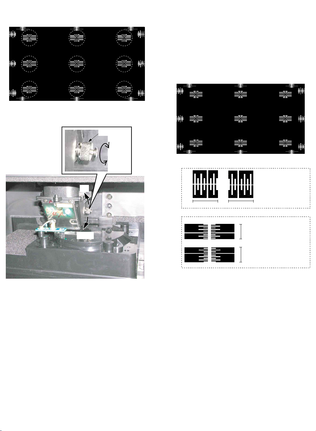
b. Focus Adjustment
1) Confirm that each of the pixels in the nine portions is
clearly visible.
OPT HPOSI 16
OPT VPOSI FE
c. Electrical Picture Position Adjustment
1) Adjust OPT HPOSI so that “C” is symmetrical to “D.” by
pressing the VOLUME UP/DOWN key on the remote to
change the value.
2) Press the CH UP/DOWN key on the remote to return to
the OTHER menu.
3) Select OPT VPOSI by pressing CH UP/DOWN key on
the remote.
4) Adjust OPT VPOSI so that “A” is symmetrical to “B” by
pressing the VOLUME UP/DOWN key on the remote to
change the value.
"E"
"F""A"
<Focus Screen>
2) If not, loosen the Knob on the Projection Lens until the
Knob can be moved.
Knob
Tighten
Loosen
Up
Down
"I"
OPT HPOSI 16
OPT VPOSI FE
"C"
"K"
"G" "H""B"
"C"
width "c"
"A"
"B"
"J"
"D"
"L"
<Focus Screen>
"D"
width "c" = width "d"
width "d"
width "a"
width "a" = width "b"
width "b"
<Front View>
Fig. 4-7
3) Adjust the Knob by moving up or down so that each of
the pixels in the nine portions is clearly visible to obtain
the best focus.
4) Tighten the Knob.
Note:
Focus Adjustment is not normally necessary. Perform this
adjustment only if necessary.
5) Confirm that all “A”, “B”, “C”, “D”, “E”, “F”, “G”, “H”, “I”, “J”,
“K”, “L” are each almost symmetrical.
6) If not, adjust the “OPT HPOSI” and “OPT VPOSI”
(repeat steps 1-6) until the picture is in the correct
position.
7) Press the CH UP/DOWN key on the remote to return to
the OTHER menu.
Page 8
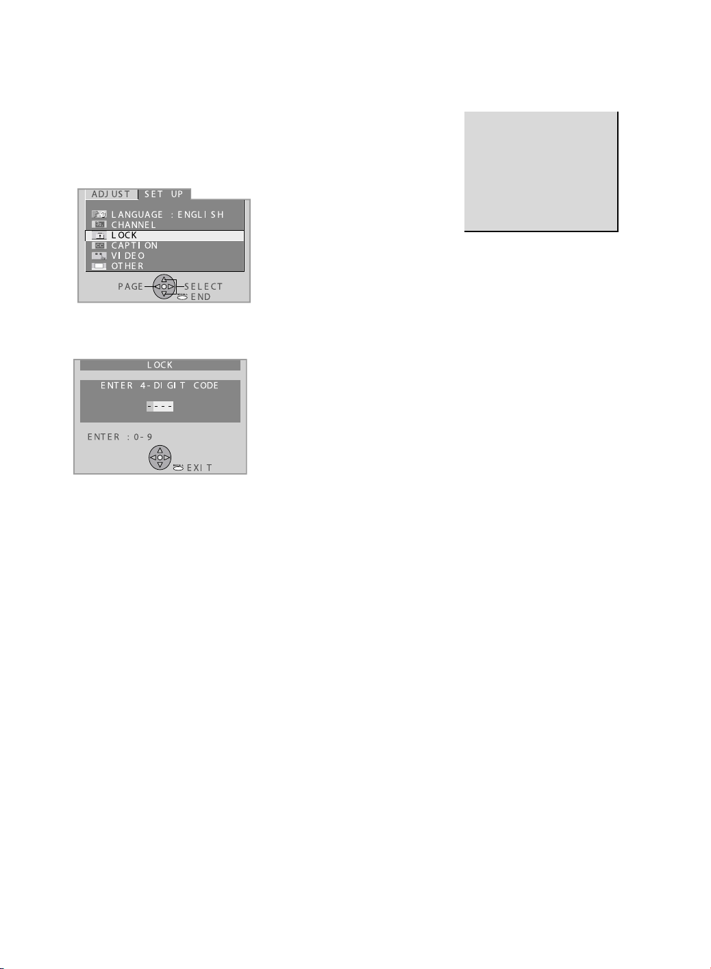
RESET USER’S MEMORY FUNCTIONS
CLOGGED AIR FILTER DETECTION
Be sure to reset the user’s memory:
• After replacing the Main C.B.A. (included in the TV/Tuner
Unit)
• If the secret code of V-chip is forgotten.
• When moving the unit to a new location.
1. Turn on the power.
2. Press the ACTION key on the remote to display the MENU
screen. Then, select SET UP. The SET UP menu will
appear.
3. Select LOCK by pressing CH UP/DOWN key on the remote.
Then, press the ACTION key. The LOCK menu will appear.
When a dirty or clogged air filter is detected, the OSD display
appears for 1 minute. And then the Lamp is turned OFF.
When this OSD display appears, remove the Projection Unit
from rear, and clean the air filters gently on the Projection Unit.
AIR FILTER CLEANING
IS RECOMMANDED AT THIS
TIME. FIRST TURN THE
UNIT OFF. PLEASE CALL FOR
SERVICE.
UNIT WILL BE TURNED
OFF AFTER 1 MINUTE.
4. Press and hold the VOLUME DOWN button on the unit and
the ACTION key on the remote for more than 5 seconds
while this LOCK menu is displayed. When reset is finished,
power shuts off automatically (the user’s memory is reset).
Page 9
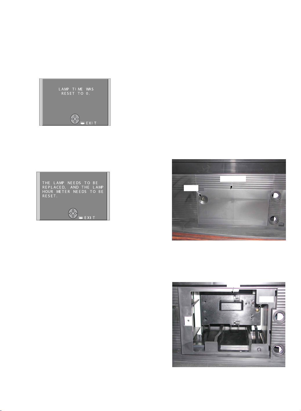
REPLACEMENT OF LAMP
Lamp Time Reset Procedure:
Be sure to reset the Lamp time to “0” after replacing the Lamp.
1. Plug in the AC Cord, and turn on the power by pressing the
POWER button.
2. Press and hold the VOLUME DOWN button on the unit and
the PIP key on the remote together for over 5 seconds in
power on condition.
When the reset is finished, the display as shown in Fig. 51 appears and the LAMP LED goes out.
Fig. 5-1
Note:
1. If the Lamp time exceeds 10,000 hours, when turning
on the power (Lamp ON), the display as shown in Fig.52 appears for about 5 minutes and LAMP LED lights up.
Lamp Replacement Procedure:
1. Press the POWER button on the remote to turn off the
power.
2. Wait for about 1 minute until the cooling fan stops.
Note:
The lamp cooling fan will continue to operate for about 1
minute after the power is turned off. Do not unplug the AC
Cord from the outlet until the fan has stopped. Avoid
interrupting the power by using circuit breakers or switchable
power strips.
3. After the cooling fan has stopped, unplug the AC Cord from
the outlet.
Note:
Please wait more than one hour before replacing the lamp.
[ Forced cooling function ]
If you need to replace the lamp more urgently:
• The Projection display has a forced cooling feature.
After the POWER button is turned OFF, and
sometime during about the first minute of the normal
cooling fan operation, press the VOLUME UP button
on the unit and CH UP key on the remote at the same
time for more than 5 seconds. The cooling fan will
operate for about 10 minutes. (LAMP LED will flash
5 times every 5 second and POWER LED will flash
red for 10 minutes.)
4. Remove the Front Cover Unit from the latches.
5. Remove the Lamp Cover by loosening the Screw.
Fig. 5-2
2. Due to variation in the way each lamp is used, the lamp
may need to be replaced before the maximum 10,000
hour limit is reached. These variations include the
number of times and the duration the lamp is lit, prolonged
use in excess of 24 hours, and any mechanical shock
the bulb may accidentally experience. In situations
where the use of this product is critical we recommend
keeping a spare bulb on hand.
WARNING:
The high-pressure lamp may explode if not properly handled.
The lamp is hot immediately after use. Touching it directly may
cause burns. Please allow the lamp to cool before handling or
replacing the lamp unit.
Avoid touching the glass portion of the bulb with your fingers.
Natural oils from your skin can cause a “hot spot” to develop,
which can cause the bulb to crack when it gets hot. In case the
bulb is accidentally touched, the area should be carefully
cleaned using isopropyl alcohol and a soft lint free cloth or
cotton ball.
Lamp Cover
Screw
Fig. 5-3
6. Loosen the Screw on the Lamp. Then, pull the Lamp.
Note:
Because the Lamp may still be hot, use caution when
handling.
Lamp
Screw
Cautions for Lamp Unit Replacement:
• Handle the removed old lamp unit carefully. If handled
improperly, it may have a risk of explosion.
• Wear gloves when replacing the lamp unit.
• If replacing the lamp unit becomes necessary during the
operation of the TV, follow the procedure below to turn off
the power and wait until the lamp unit cools completely.
Fig. 5-4
7. Install the new Lamp, and tighten the Screw.
8. Install the Lamp Cover securely, and tighten the Screw.
9. Install the Front Cover Unit.
Note:
After replacing the Lamp, use caution to reset the Lamp time.
Page 10
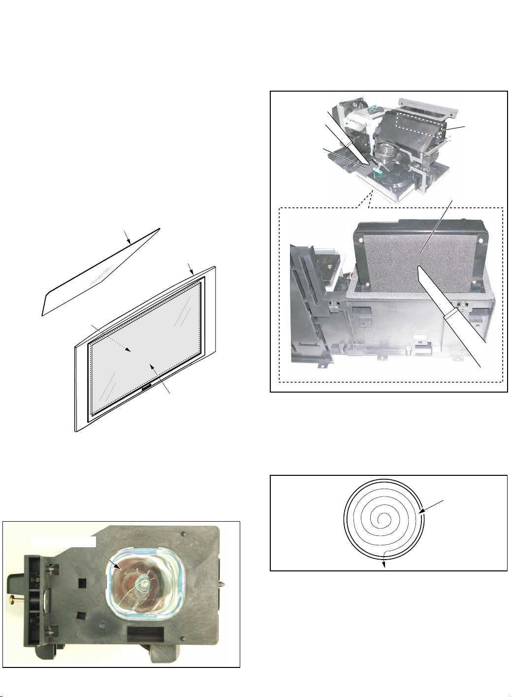
Lens
CLEANING METHOD
Air Filter
Air Filter
Air Filter
<Bottom View>
THE FILTER ON THE PROJECTION UNIT
THE SCREEN UNIT AND THE MIRROR
•THE SCREEN UNIT (Lenticular Screen, Fresnel Lens)
The Lenticular Screen surface should be wiped gently with a
clean, soft, dry cloth. If the dirt cannot be removed by wiping
with a dry cloth, lens cleaner can be used. Wipe evenly so as
not to leave any streaks.
Note:
Do not use cleaning materials containing methyl alcohol,
acetone, or dichloromethane.
Wipe the surface of the Fresnel Lens with a clean, soft, dry
cloth.
•THE MIRROR
Remove any dirt with a compressed air blower or wipe with a
clean, soft, dry cloth. If wiped too forcefully, the surface of the
Mirror can be damaged. If wiping with a clean, dry cloth does
not remove the dirt, the Mirror must be replaced.
Mirror
Screen Unit
CAUTION:
Operating with torn or damaged Air Filter may cause damage
to the Projection unit.
Remove the Projection Unit from rear. Then, clean the filters on
the Projection Unit. Gently remove any accumulated dust from
filter with a vacuum cleaner.
Fresnel Lens surface
(inside)
Lenticular Screen surface
(outside)
THE LAMP
Gently wipe the surface of the glass of the Lamp with cleaning
paper or soft cloth.
Surface of glass
Fig. 6-1
Fig. 6-3
THE PROJECTION LENS
Use lens cleaning paper and cleaner available at your local
camera shop, etc. Dampen the cleaning paper with cleaner
and gently wipe the surface of the lens from the center outward
to remove dust.
Fig. 6-4
Fig. 6-2
THE POLARIZER UNIT, THE FIELD LENS, THE RELAY
LENS, THE CONDENSER LENS, THE DICHROIC
MIRROR, THE FULL MIRRORS, THE INTEGRATOR AND
THE P/S CONVERTER
Make sure that no dust gets on the optical components such as
the Polarizer Unit, the Field Lens, the Relay Lens, the Condenser
Lens, the Dichroic Mirror, the Full Mirrors, the Integrator and
the P/S Converter. Clean these optical components with
cleaning paper moistened with lens cleaner if necessary.
Page 11
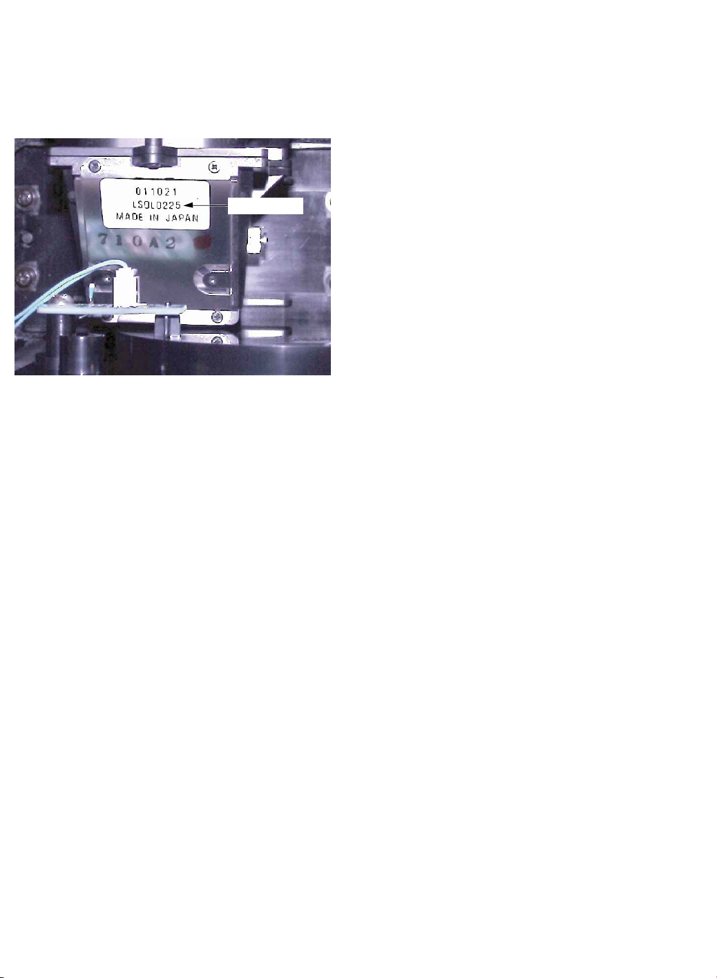
TO DISTINGUISH THE PROJECTION
LENS UNIT OR THE PROJECTION UNIT
DO NOT UNPLUG AC CORD DURING
COOLING OPERATION
The only difference between the 50 inch model and the 60 inch
model of the Projection Unit is the Projection Lens. To
distinguish, see label on the Projection Lens.
50 inch model as shown
LSDL0225
<Front View>
LSDL0225 with white label: for 50 inch model
LSDL0248 with Yellowish green label: for 60 inch model
Fig. 7
The lamp cooling fan will continue to operate for approximately
1 minute after the power is turned off.
At the same time, the POWER LED will flash red.
Do not disconnect the AC Cord from the power outlet and do
not open any circuit breakers while the cooling fan is still
operating.
HOT CIRCUIT
Primary circuit exists on the Audio Amp C.B.A., the Ballast
C.B.A. and the Power C.B.A.
This circuit is identified as "HOT" on the C.B.A. and in the
Service Manual. Use extreme care to prevent accidental shock
when servicing.
Note:
LSDL0225 and LSDL0248 are not the part numbers of the
Projection Lens as a replacement part.
Page 12
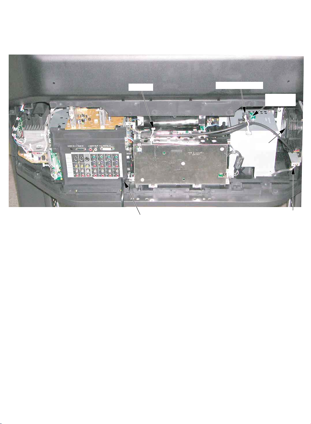
WIRE AND LEAD POSITION DIAGRAM OF THE UNIT
After servicing, make sure that all wires, leads, and clampers are placed in their original position. It is important for the best
operation of the unit.
Note: Use extreme care especially for the following.
Clamper
Thermal Fuse Unit
Fan 3
Thermistor
2 C.B.A.
GND Wire
AC Cord
Fig. 9-1
Page 13
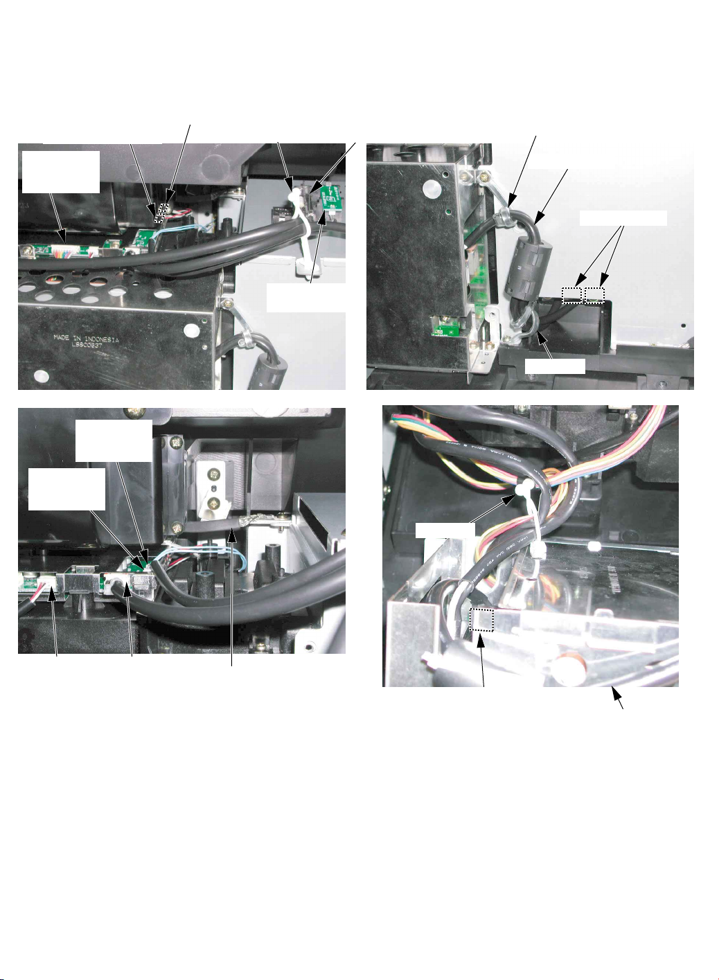
After servicing, make sure that all wires, leads, and clampers are placed in their original position. It is important for the best
operation of the unit.
Note: Use extreme care especially for the following.
P1306 (From Thermal Fuse Unit)
Ballast C.B.A.
Clamper
Clamper
Lamp Sockets
Lamp Cable
Clamper
GND Wire
P2304 (From
Thermistor 2
C.B.A.)
P2904
(From Fan 3)
P2903
(From Fan 2)
P2306 (From
Cover Switch
C.B.A.)
Clamper
Thermistor 2
C.B.A.
Thermal Fuse Unit
P2901
(From Power
C.B.A.)
P2303 (From
Thermistor 1 C.B.A.)
P2902 (From Fan 1)
Fig. 9-2
Page 14
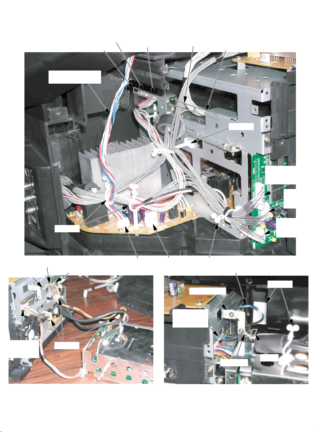
After servicing, make sure that all wires, leads, and clampers are placed in their original position. It is important for the best
operation of the unit.
Note: Use extreme care especially for the following.
Clamper
Clampers
No connection
20-pin Cable
P6003
(From Tuner
C.B.A.)
Clamper
P5501
(From Front
Jack C.B.A.)
P6305
(From Operation
C.B.A.)
No connection
No connection
P4503
(Speaker)
P5302
(From LCD
Drive C.B.A.)
GND Plate A
GND Wire
P2501
P3401
(from Power
C.B.A.)
P6002 (from
Ballast C.B.A.)
P4501
(From Power
C.B.A.)
P3502
(From Front Jack
C.B.A.)
Clamper
Speaker Connector
Leads
P3501
(From Tuner
C.B.A.)
P3603
(From Audio
Amp C.B.A.)
Clamper
No connection
Fig. 9-3
Page 15
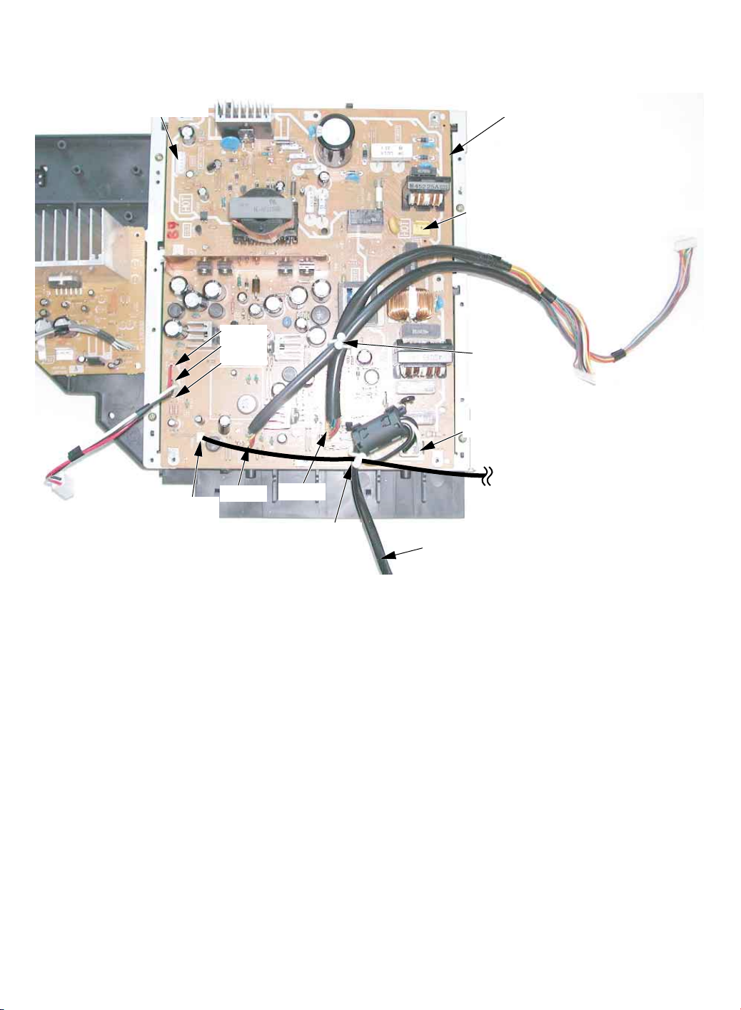
After servicing, make sure that all wires, leads, and clampers are placed in their original position. It is important for the best
operation of the unit.
Note: Use extreme care especially for the following.
Clamper
P1007
P1008
P1009
P1010
P1011
P1006
(To Fan 4)
P4501
(To Audio
Amp C.B.A.)
Clamper
P1001 (To Ballast C.B.A.)
P805 (To Ballast C.B.A.)
P804
Fan 4
P2901
(To LCD Drive
C.B.A.)
P3401
(To Main C.B.A.)
AC Cord
Power C.B.A.
Fig. 9-4
 Loading...