

Page 1
INSTRUCTIONS - MAX® ImagePRO
™
-EX Series (15Amp and 20Amp)
Important Safety Points
Panamax surge protectors and the connected equipment must be indoors in a dry
location and in the same building. Although
your Panamax protector is very durable, the
internal components are not isolated from
the environment. Do not install any
Panamax product near heat emitting appliances such as a radiator or heat register.
Do not install this product where excessive
moisture is present.
It is not uncommon for a building to be
improperly grounded. In order to protect
your equipment, Panamax products must
be plugged into a properly grounded 3-wire
outlet. Additionally, building wiring and
grounding must conform to applicable NEC
(USA) or CEC (Canada) codes for the
Panamax warranty to be valid.
Do not use 2-blade ground adapters with
this product. If an extension cord is
required, use only Panamax #GEC1410. If
your surge protector indicates a Line Fault,
do not use the product. Call your electrician
to correct the building’s wiring.
CAUTION – Do not install this device
if there is not at least 10 meters (30 feet)
or more of wire between the electrical
outlet and electrical service panel.
Power Filtration and Surge
Protection for Digital Office
Equipment
The MAX® ImagePRO™ EX Series is
designed to provide clean power and protect digital office equipment from a variety
of undesirable power
components are prone to operating at unacceptable performance levels when exposed
to EMI/RFI interference or power fluctuations (surges and spikes). Without the
proper protection,digital equipment may
experience data loss, lock-ups or even circuit damage. The MAX
series will protect your digital office equipment from a combination of power problems including, normal and common mode
EMI/RFI noise interference, ground noise,
surges, spikes, and sustained over-voltages.
® ImagePro™-EX is available in
The MAX
15-Amp (MIP-15A-EX) and 20-Amp (MIP20A-EX) models. This includes:
Firewall for Noise™ Circuitry – This
technology provides enhanced Neutral-toGround Noise Filtration for your digital
office equipment. EMI/RFI noise can
contaminate the equipment safety ground,
which in turn will contaminate the connected digital equipment, and prevent it from
operating at peak performance levels.
conditions. Digital
® ImagePRO-EX
GFCI Compatibility
This circuit features an improved 2-satge
common-mode architecture that provides
compatibility for GFCI’s ans NEC article
250.6.
Firewall for Noise™ - circuitry prevents
EMI/RFI noise from contaminating the connected digital equipment through the
ground wiring.
Automatic Voltage Monitoring (AVM )–
This power monitoring system acts as a
gate to prevent unsafe voltages from damaging sensitive electronic equipment. It
automatically detects a prolonged over-voltage and disconnects the power to the connected equipment, then reconnects it when
the power returns to a safe level. It even
protects the MAX
Wiring Fault Safety Shutoff – This technology will detect a miswired wall receptacle or
an open-ground by monitoring the voltage
between neutral and ground. If an unsafe
condition exists, the MAX
disconnect the power from the connected
equipment.
® ImagePro™ unit.
® ImagePro™ will
SignalPerfect™ Te lephone Line Protection
Two pairs of RJ-11 phone jacks are available to protect a single-line telephone
modem (pins 4,5 protected) with fuseless
Auto-Resetting technology and optimized
circuitry to ensure a clean, clear signal.
Ethernet LAN Protection – Two pairs of
RJ-11/45 jacks are available to protect one
Ethernet 10/100 Base-T network connection
(all pins protected).
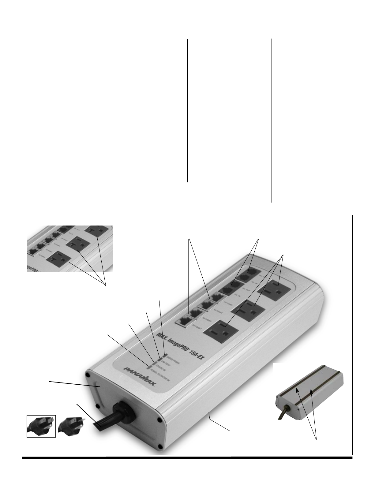
Diagnostic lights -
Power ON and Protection OK- (green)
normally ON - indicates that the surge
protector is functioning properly, power
is on, and it is protecting all connected
equipment.
Ground OK – (green) normally ON indicates that the wall outlet is properly
wired.
Line Fault – (red) normally OFF - when
lit, indicates that the wall outlet is
improperly wired.
Unsafe Power – (red) normally OFF –
when lit, indicates that incoming voltages
are unsafe and the surge protector has
disconnected the power to protect your
equipment or that there is a wiring fault.
Features
MIP-20A-EX
20 Amp AC configured receptacles
Unsafe Power Indicator light
Line Fault Indicator light
Ground OK Indicator light
Protection OK Indicator light
Three-stage, GFCI
Compatible filter circuit
provides high levels of
Normal and Common
mode EMI/RFI noise
filtration
•
LAN Protection
2 pairs of RJ-45
bi-directional connectors
(2 LAN cables included)
Telephone Protection
2 pairs of RJ-11
In/Out connectors
(2 telco cable included)
•
Separate protection
circuits for 10/100 BaseT
Ethernet and telephone
•
Three Always-on AC outlets
•
(20 Amp MIP20)
(15 Amp MIP15)
•
•
•
•
•
Wall mountable
(Velco strips
included).
Includes security
lock to prevent theft.
Eight foot power cord
15 amp plug
MIP-15A-EX
•
20 amp plug
MIP-20A-EX
Two rubber strips running the length of the product
provide a non-slip grip and prevent marring surface.
•
INS00812 REV. C 7/09
Page 2
10/100
BT
IN
1
0/100
BT
OUT
TEL IN
TEL OUT
TEL IN
TEL OUT
10/100BT
IN
10/100BT
OUT
MAX
®
ImagePRO
™
15 Amp EX
U
NSAF
E
P
OWER
LINE
FAU
L
T
GRO
UND
O
K
PO
WER
/
F
I
LTRATION O
K
®
INSTRUCTIONS - MAX® ImagePro™EX Series (15Amp and 20Amp)
Properly Connecting Your
Surge Protector
To completely protect your equipment from
power surges, every wire leading into or out
of the equipment you want to protect must
be connected to the appropriate Panamax
surge protector. Damaging lightning and
power surges can get into your system
through any AC power or signal line (phone
lines, grounding wires, LAN cables, modem
cables, etc.) connected to your electrical
equipment.
Installation Procedures
1. Turn OFF the power to all equipment that
will be plugged into the unit.
2. Plug the protector into a properly grounded AC outlet.
3. Once proper AC wiring and grounding has
been established via a green “Ground OK”
light, plug the equipment to be protected
into the AC outlets on the unit.
4. Note the position of the IN and OUT jack
on the ImagePro™ -EX unit. The IN jacks
are for the line connections that come from
the wall or floor jack. The OUT jacks are the
line connections to your connected equipment.
5. Plug the incoming LAN and/or telephone
line into the appropriate IN jack. The line
should now be connected between the wall
and the unit.
6. Plug the LAN and/or phone cord into the
appropriate OUT jack. Plug the other end
into the equipment to be protected.
7. One at a time, turn each piece of connected equipment ON and check for power and
correct operation.
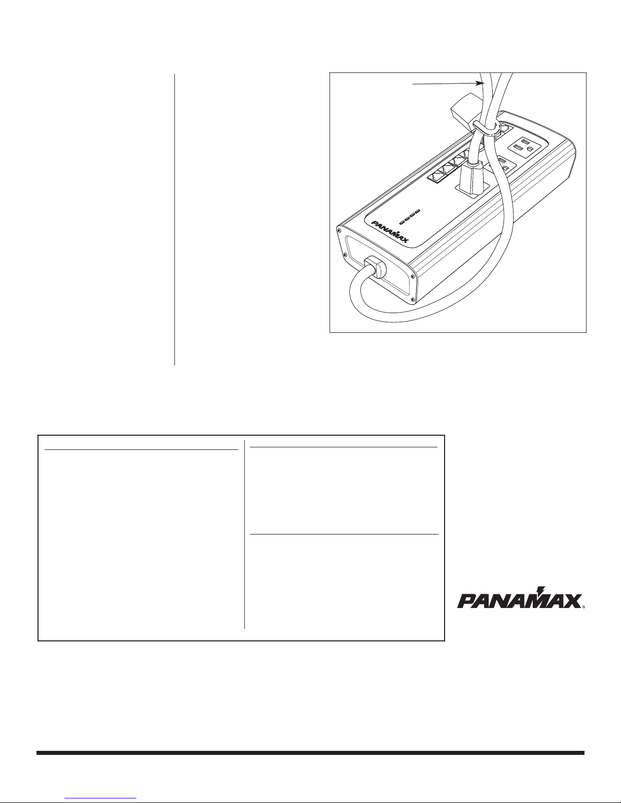
Security Lock Installation
Security Lock – An equipment-to-protector
cord security lock is included with the
® ImagePro™. This feature will allow
MAX
the user to attach and lock the connected
equipment’s power cord to the protector.
This will insure that the protector remains
connected to the office equipment, which is
a useful tool for ensuring the validity of
service agreements.
1. Open the security lock and route both
power cords (surge protector and connected equipment) through the hasp.
2. Close the lock around the power cords.
Your equipment is now locked to the
MAX
® ImagePro™.
AC line from
connected
equipment.
MAX® ImagePRO-EX PRODUCT SPECIFICATIONS
AC SURGE PROTECTION
Line Voltage…………………............……………..120VAC, 50/60Hz
Maximum Current Rating
MIP15……….............................…………………………….15A
MIP20………….............................………………………….20A
EMI/RFI Noise Filtration………….........…….65 dB (100KHz - 1 MHz)
Thermal Fusing……………........................………………..…….Yes
SurgeGate™ Circuitry…….............................……………………Yes
Overvoltage Shutoff…………….................…………..146V ± 8V
Protect or Disconnect™ Circuitry…..........................................…..Yes
Single Pulse Energy Dissipation……..…...................…...1650 Joules
Peak Impulse Current………………..................………52,000 Amps
Voltage Protection Rating (UL1449 3rd Edition, 3,000A).............500V
Protection Modes………………………................…...L-N, L-G, N-G
Initial Clamping Level…………….......................………….200 Volts
Surge Response Time………….....................……….<1 nanosecond
TELEPHONE PROTECTION
Pins Protected……………………….........……RJ-11/45, pins 4,5
Protection Modes……………………...…..Metallic & Longitudinal
Clamping Level………...........................…………………….260V
Capacitance……………………………...................30pf (approx.)
10/100 Base-T LAN PROTECTION
Pins Protected…………………….......……RJ-11/45, pins 1,2,3,6
Protection Modes…………………......….……..All pins to ground
Clamping Level……….............................……………………...7V
CONTACTING PANAMAX
For product and warranty information or
other general information, please contact
PANAMAX Customer Relations at:
Email: [email protected]
Web: www.panamax.com
Fax: 707-283-5901
Toll Free:800-472-5555 or
Phone: 707-283-5900,
7:30 AM - 4:30 PM, PST
1690 Corporate Circle, Petaluma, CA 94954
800-472-5555 • www.panamax.com
© 2009 Panamax, Inc.. MAX and the Panamax logo are registered US trademarks of Panamax. ImagePro, SignalPerfect, Firewall for Noise and Protect or Disconnect are trademarks of Panamax.
INS00812 REV. C 7/09
 Loading...