

Panacom H.264 8 / 16CH D1 User Manual

Thank you for purchasing our product.
Please read this User’s Manual before
using the product. Change without Notice
H.264 8 / 16CH D1 DVR
User’s Manual

2
CAUTION
z Please read this user manual carefully to ensure that you can use the device correctly and safely
z We do not warrant all the content is correct. The contents of this manual are subject to change
without notice
z This device should be operated only from the type of power source indicated on the marking label.
The voltage of the power must be verified before using. If not in use for a long time, pull out the plug
from the socket
z Do not install this device near any heat sources such as radiat ors, heat registers, stoves or other
device that produce heat
z Do not install this device near water. Clean only with a dry cloth
z Do not block any ventilation openings. And ensure well ventilation around the machine
z Do not power off the DVR at normal recording condition! The correct operation to shut off DVR is to
stop recording firstly, and then select “shut-down” button at the right of the menu bar to exit, and finally
to cut off the power.
z This machine is indoor using equipment. Do not expose the machine in rain or moist environment. In
case any solid or liquid get into the machine’s case, please cut off the power supply immediately, and
ask for qualified technicians to check the machine before rest art
z Refer all servicing to qualified service personnel. No any parts repaired by yourself without technical
aid or approval.
z This manual is suitable for 8/16-channel digital video recorders.
3
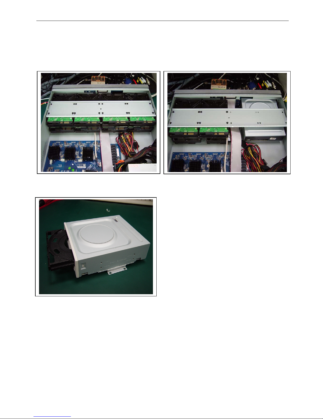
Install Hard Drive
1. Unscrew and open the top cover
2. Connect the power and data cables. Place the HDD onto the bottom case as below.
3. Screw the HDD. For the convenience to install, please connect the power and data cables firstly, and then
screw to fix.
Install HDD x 8 Install HDD x 4 and DVD writer
Install DVD writer

4
1.1
Main Features
COMPRESSION FORMAT
• Standard H.264 compression with low bit rate and better image quality
LIVE SURVEILLANCE
• Support HD VGA output and HDMI output
• Support channel security by hiding live display
• Display the local record status and basic information
• Support USB mouse to make full control
RECORD MEDIA
• Support 8 SATA HDD(FAT32 file system)
BACKUP
• Support USB 2.0 or eSATA devices to backup
• Support internal or external DVD writer to backup
• Support saving recorded files with AVI standard format to a remote computer through internet
RECORD & PLAYBACK
• Record modes: Manual, Schedule, Motion detection and Sensor alarm recording
• Support overwrite after HDD full
• Resolution, frame rate and picture quality are adjustable
• 128MB for every video file packaging
• 8/16 audio channels available
• Two record search mode: time search and event search
• Support 8/16 screen playback simultaneously
• Support deleting and locking the recorded files one by one
• Support remote playback in Network Client through LAN or internet
ALARM
• 4 channel alarm output and 8/16 channel alarm input available
• Support schedule for motion detection and sensor alarm
• Support pre-recording and post recording
• Support linked channels recording once motion or alarm triggered on certain channel
• Support linked PTZ preset, auto cruise and track of the corresponding channel
PTZ CONTROL
• Support various PTZ protocols
• Support 128 PTZ presets and 8 auto cruise tracks
• Support remote PTZ control through internet
SECURITY
• Customize user right: log search, system setup, two way audio, file management, disk management,
remote login, live view, manual record, playback, PTZ control and remote live view
• Support 1 administrator and 63 users
• Support event log recording and checking, events unlimited
NETWORK
• Support TCP/IP, DHCP, PPPoE, DDNS, UPnP protocol
• Support IE and Apple safari browser to do remote view
• Support setup client connection amount
• Support dual stream. Network stream is adjustable independently to fit the network bandwidth and
environment.
• Support picture snap and color adjustment in remote live
• Support remote time and event search, and channel playback with picture snap
• Support remote PTZ control with preset and auto cruise
• Support remote full menu setup, changing all the DVR parameters remotely
• Support mobile surveillance by smart phones , symbian, Windown Mobile, Iphone or Android, 3G network
available
• Support CMS to manage multi devices on internet
5
1.2
Front Panel Instructions
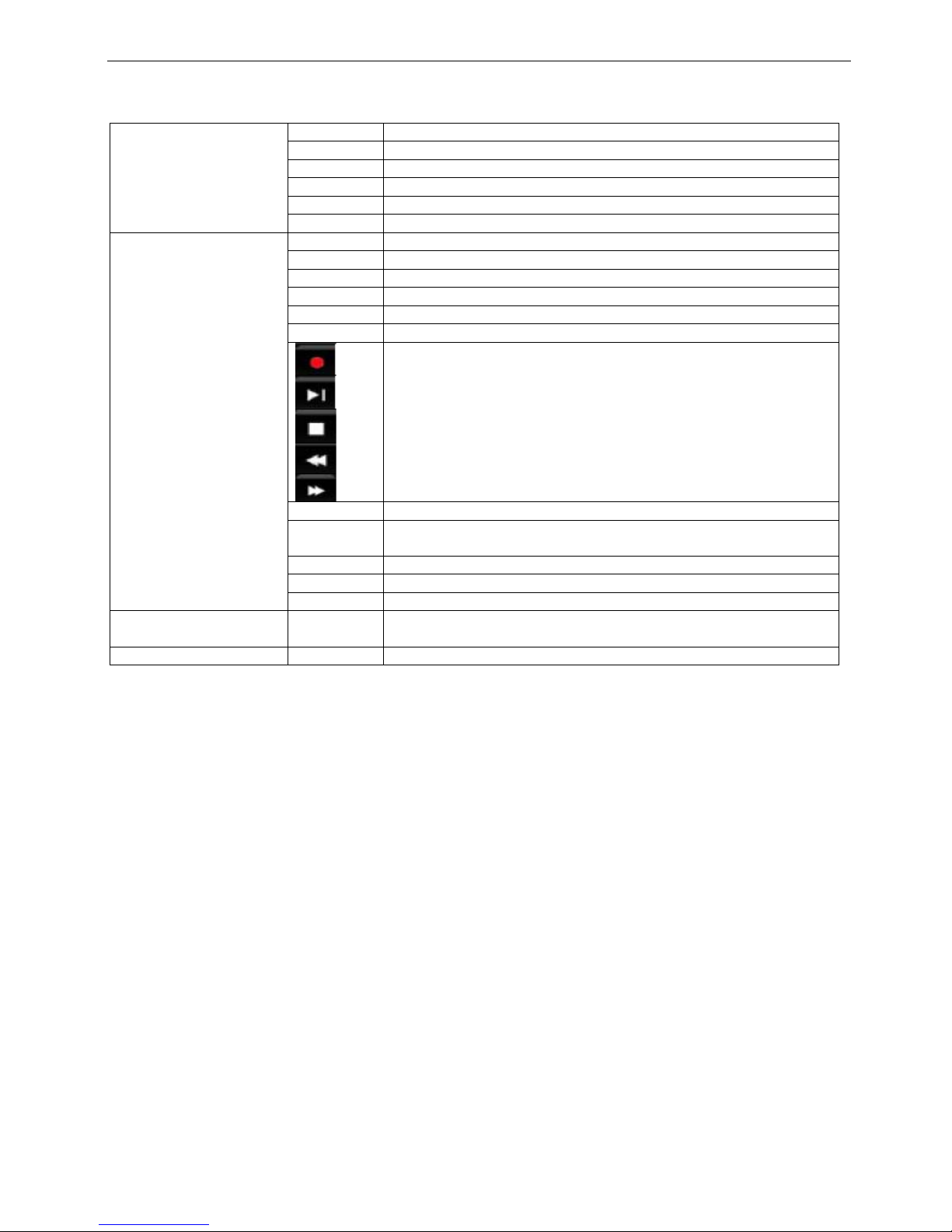
Power Power indicator, when connection
HDD When HDD is writing and reading
Net When access to network
Backup When backup files and data
Play When playing video
LED indicator
REC When recording
Audio/+ 1. Control voice 2. Increase the value in setup
PTZ/- 1. Enter PTZ mode in live 2. Decrease the value in setup
MENU Enter menu in live
INFO Check system information data
Backup Enter backup mode in live
Search Enter search mode
Record manually
Play/Pause
Stop/Esc
Rewind
Rewind
1-9 Input number 1-9 or choose camera
0/10+ Input number0, 10 and the above number together with other digital
keys
Direction Change direction to select items
Multi-screen Change screen display mode like1/4/9/16 channel
Button
Enter Confirm selection
USB
USB port To connect external USB devices like USB flash, USB HDD,
USB VCD/DVD
6
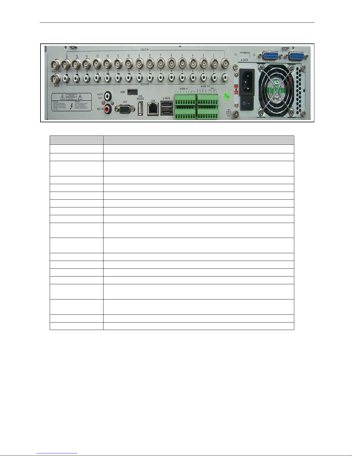
1.3 Rear Panel Instructions
The rear Panel interface for 8/16-ch is shown as Fig 2.9:
Fig 2.9 Rear Panel for 8-ch
Name Description
Video out Connect to monitor
Video in Video input channels from 1-8(8ch) / 1-16(16ch)
Spot out
Connect to monitor as an AUX output channel by channel.
Only video display, no menu show
Audio out Audio output, connect to the sound box
MIC IN Talk
VGA port VGA output, connect to monitor
Audio in 8ch: 8ch audio in / 16ch: 16ch audio in
USB Only USB mouse
LAN Network port
ALARM IN
8ch: Connect to external sensor1-8
16ch: Connect to external sensor1-16
ALARM
OUT
4ch relay output. Connect to external alarm.
P/Z Connect to speed dome
K/B Connect to keyboard
GND Grounding
FAN For cooling the device
POWER
INPUT
AC 115V or 230V
POWER
SWITCH
Switch on/off
HDMI to HDMI input
e-SATA e-SATA device connection
Tab 2.5 Definitions of Front Panel Buttons
7
1.4
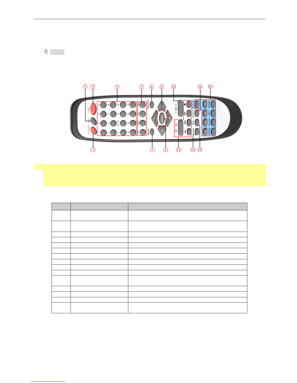
Remote Controller (Optional)
It uses two AAA size batteries and works after loading batteries as following:
Step1: Open the battery cover of the Remote Controller
Step2: Place batteries. Please take care the poles (+ and -)
Step3: Replace the battery cover
Notice: Frequently defect checking as following
1. Check batteries poles
2. Check the remaining charge in the batteries
3. Check IR controller sensor is mask
If it still doesn't work, Please change a new remote controller to try, or contact your dealers
The interface of remote controller is shown in Fig2.11 Remote Controller.
◆ Switch Remote Control ID
Take remote control and point to DVR then continuously press “8”,”8”,”ID(0-65535)”,”Enter”.
*The ID must be the same on DVR.
*For example: If ID=1, please take remote control and point to DVR then press 8,8,1,Enter.
*Repeat to release ID
Fig 2.11 Remote Controller
Item Name Function
1 Power Button
Soft switch off to stop firmware running. Do it before
power off.
2 INFOR Button
Get information about the DVR like firmware version,
HDD information
3 REC Button To record manually
4 Digital Button Input digital or choose camera
5 Multi Screen Button To choose multi screen display mode
6 SEARCH Button To enter search mode
7 MENU Button To enter menu
8 ENTER Button To confirm the choice or setup
9 Direction Button Move cursor in setup or pan/title PTZ
10 +/- Button To increase or decrease the value in setup
11 Playback Control Button
To control playback, Fast forward/rewind/stop/single
frame play
12 AUDIO Button To enable audio output in live mode
13 Auto Dwell Button To enter auto dwell mode
14 BACKUP Button To enter backup mode
15 PTZ Control Button
To control PTZ camera:
Move camera/ZOOM/FOCUS/IRIS/SPEED control
8
1.5 Control with Mouse
1.5.1 Connect Mouse
It supports USB mouse through the ports on the rear panel, please refer to Fig 2.11 Remote Controller.
Notice: If mouse is not detected or doesn't work, check below steps:
1. Make sure the mouse plugs in the USB mouse port not the USB port
2. Change a mouse to try
1.5.2 Use Mouse
The structure of the main menu is shown in Fig 2.11 Remote Controller.
In live:
Double-click left button on one camera to be full screen display. Double-click again to return to the previous
screen display.
Click right button to show the control bar at the bottom of the screen as Fig 2.11 Remote Controller. Here are all
control and setup. Click right mouse again to hide the control bar.
In setup:
Click left button to enter. Click right button to cancel setup, or return to the previous.
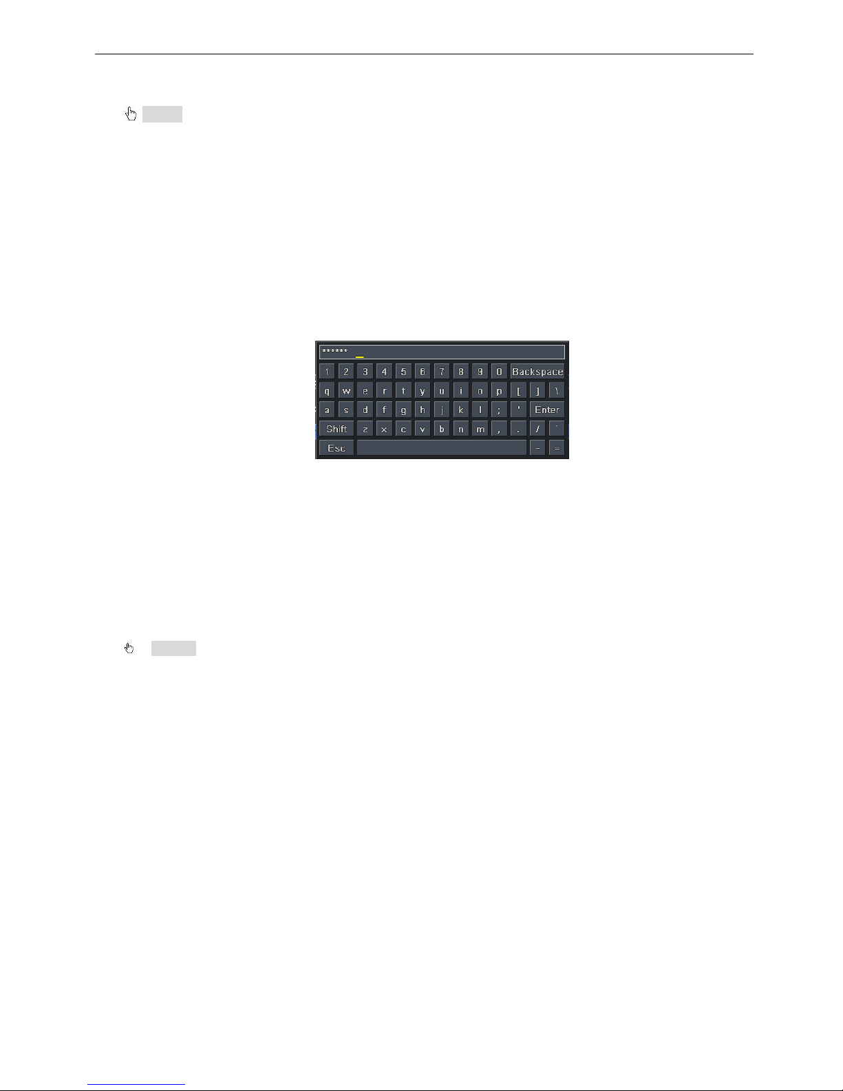
If want to input the value, move cursor to the blank and click. An input window will appear as Fig2.12. It
supports digitals, letters and symbols input.
Fig 2.12 Digital Numbers and Letters Input Window
Users can change some value by the wheel, such as time. Move cursor onto the value, and roll the wheel
when the value blinks.
It supports mouse drag. I.e. Set motion detection area: click customized, hold left button and drag to set motion
detection area. Set schedule: hold left button and drag to set schedule time
In playback:
Click left button to choose the options. Click right button to return to live mode.
In backup:
Click left button to choose the options. Click right button to return to previous picture.
In PTZ control:
Click left button to choose the buttons to control the PTZ. Click right button to return to live.
Notice: Mouse is the default tool in all the operation below unless Exceptional indicatio n.
9
2 Basic Function Instruction
2.1 Power On/Off
Before you power on the unit, please make sure all the connection is good.
2.1.1 Power on
Step1: connect with the source power; switch on the power button near the power port in the rear panel
Step2: the device will be loaded, and the power indicator will display blue
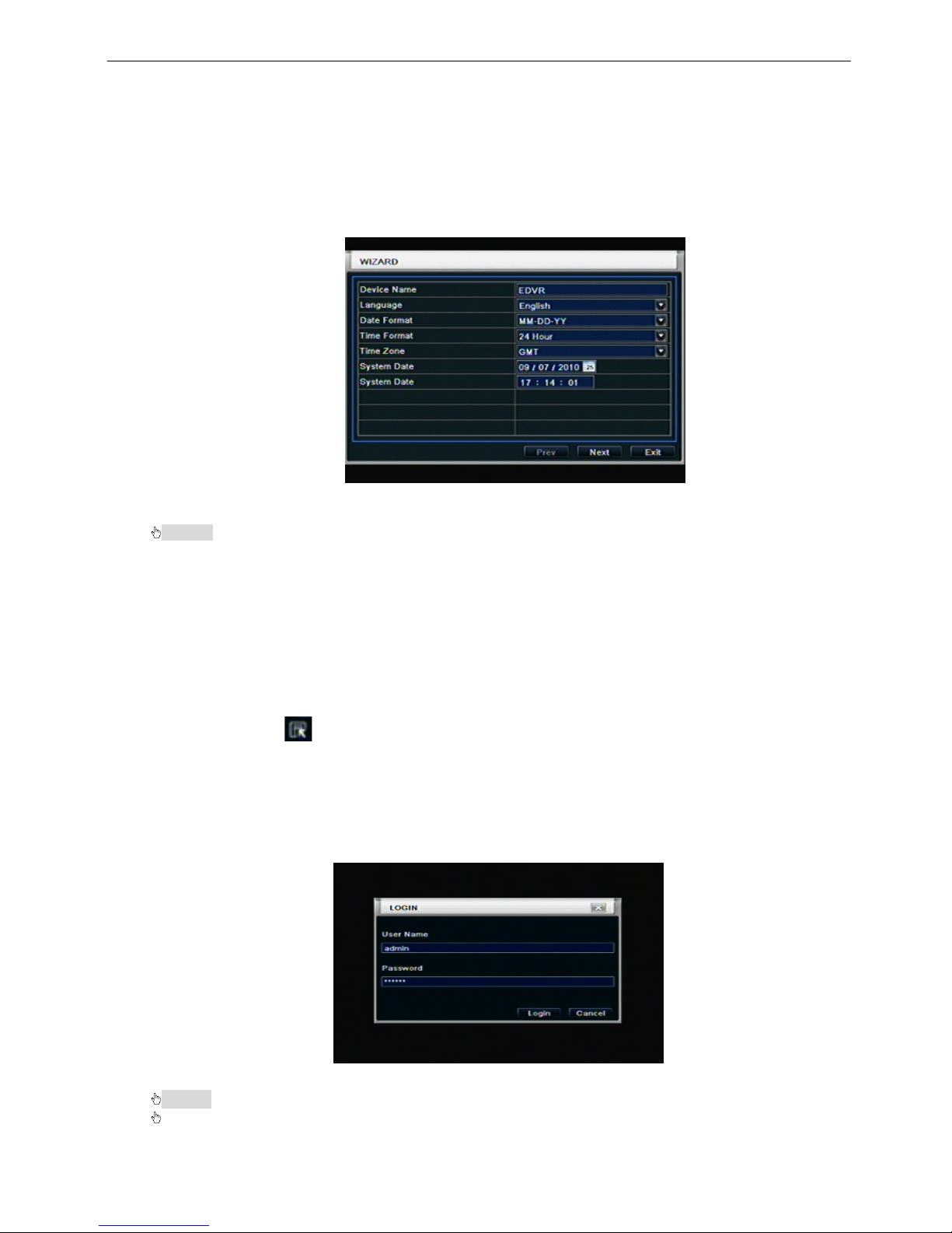
Step3: before start, a WIZARD dialogue box will be pop-up (refer to below picture) and show some
information about time zone and time setup, IP information, record quick setup and HDD information page.
After the device power on, if there is no menu or only has live image display, user can long press ESC
button to switch.
Notice: this serial device can only display menu on VGA monitor or BNC monitor at one time, if there is
live image display without menu display, please check up whether other device has menu display firstly, or
long press ESC key to wait for login dialog box to appear.
2.1.2 Power off
User can power off the device by using remote controller、keyboard and mouse.
By remote controller:
Step1: press Power button, the Shut down window will appear, click OK, the unit will power off after a while.
Step2: disconnect the power
By keyboard and mouse:
Step1: enter into Menu, then select “System Shut Down” icon, the Shut down window will appear
Step2: click OK, the unit will power off after a while.
Step3: disconnect the power
2.2 Login
User can login and logout the DVR system. User cannot do any other operations except changing the
multi-screen display once logout.
Fig 3-1 Login
Notice: the default user name and password is “admin” and 123456”
The concrete operation steps for change password, add or delete user please refer to Fig 3.7 User
management configuration for more details.
10
2.3
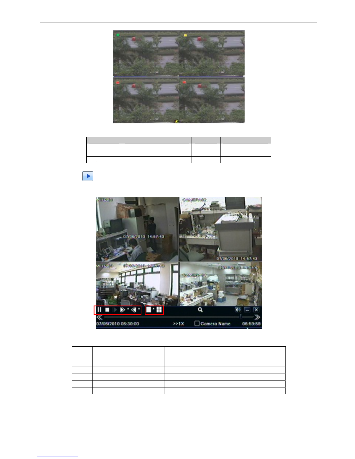
Live preview
Fig 3-2 live preview interface
The explanation of symbol in the live preview interface:
symbol meaning symbol meaning
Green
Manual record or time
record
Red Alarm record
Yellow Motion detection record Blue Schedule record
2.3.1 Live playback
Click Play
button to playback the record. Refer to Figure3-3. User can do concrete operation by click the
buttons on screen.
Fig 3-3 live playback
1 Playback process button Play/pause / stop / frame / forward / rewind
2 Playback screen mode 4ch:1/4, 8ch:1/4/9, 16ch:1/4/6/9/16
3 Playback screen magnifier Screen digital zoomx2
4 Playback volume Volume mute on/off
5 Playback bar Hide playback tool bar
6 Playback close Exit playback to search page
7 Playback process bar Last/next segment of record and time process
① ② ③ ④ ⑤ ⑥
⑦
11
3 Main menu setup guide
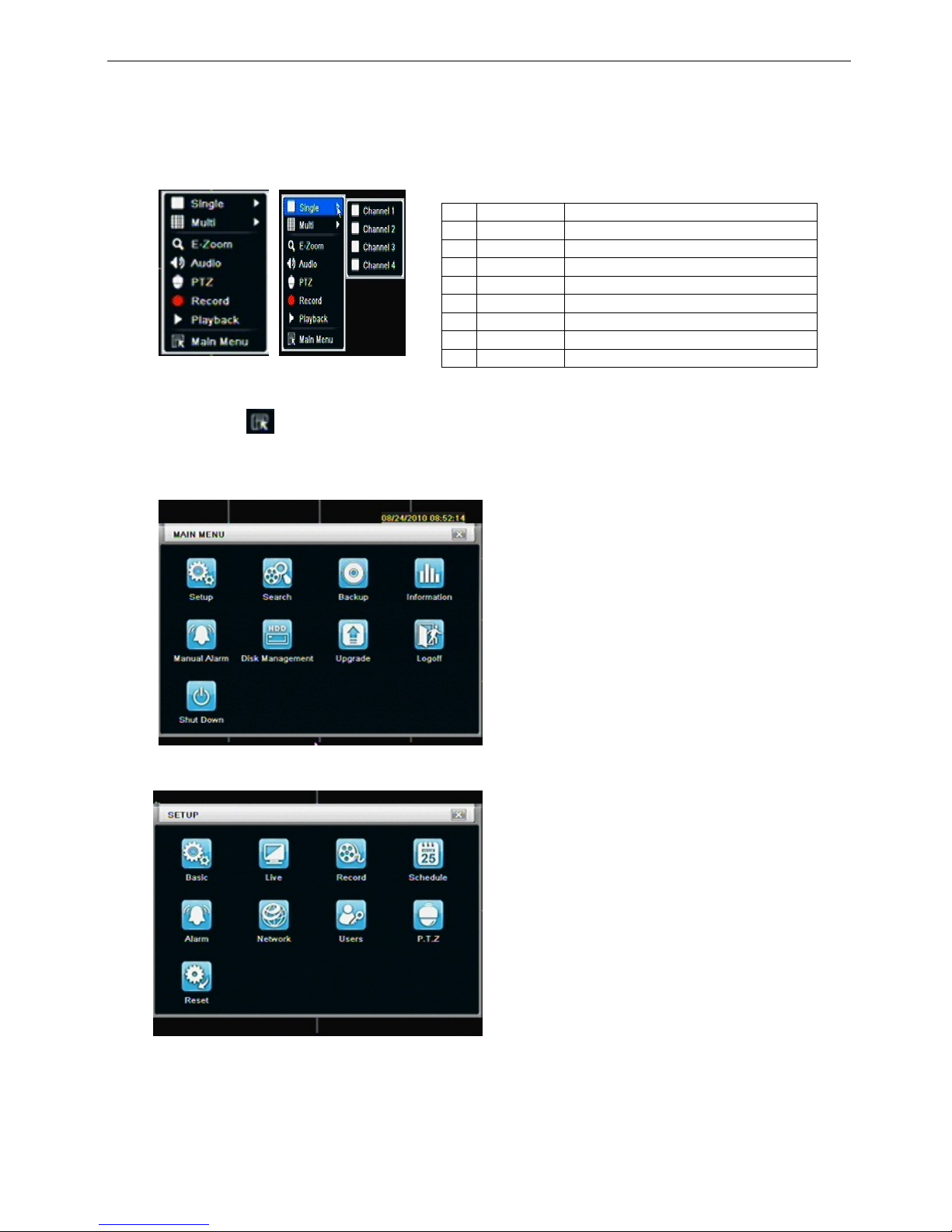
Click right mouse or press ESC button on the front panel, the control bar will display on the screen, refer to
Fig 4-1:
1 Single Full channel
2 Multi 4ch:1/4, 8ch:1/4/9, 16ch:1/4/9/16
3 E-Zoom Live/playback digital zoomx2
4 Audio Audio channel setup and volume
5 PTZ Into PTZ control mode
6 Record Manual record
7 Playback Playback the nearest file
8 Main Menu Into main OSD
9 Dwell Channel sequence(only 16CH)
Fig 4-1 main menu toolbar
Click Menu button, the interface will pop-up as Fig 4-2; press MENU button on the front panel or
operate with remote controller also can display the main menu.
Main OSD
Fig 4-2 system setup
Full channel switch, camera 1 ~ 4 or camera 1 ~ 8, camera 1 ~ 16
①
②
③
④
⑤
⑥
⑦
⑧
12
3.1
Basic configuration
Basic configuration includes three sub menus: system、date& time and DST.
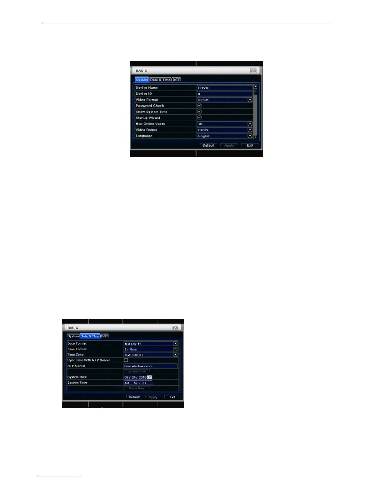
3.1.1 System
Step1: enter into system configurationÆbasic configurationÆsystem; refer to Fig 4-3:
Fig 4-3 basic configuration-basic
Step2: in this interface user can setup the device name, device ID, video format, max network users, VGA
resolution and language. The definitions for every parameters display as below:
Device name: the name of the device. It may display on the client end or CMS that help user to recognize
the device remotely.
Video format: two modes: PAL and NTSC. User can select the video format according to that of camera.
Password check: enable this option, user needs to input user name and password can do corresponding
operations with the relevant right in system configuration.
Show time: display time in live.
Show wizard: tick off this item, there will display an opening wizard with time zone and time setup
information
Max network uses: set the max user amount of network connection
VGA resolution: the resolution of live display interface, range from: VGA800*600、VGA1024*768、
VGA1280*1024and CVBS
Note:When switch between VGA and CVBS will change the menu output mode, please connect to
relevant monitor.
Language: setup the menu language.
Note: after changed the language and v i deo output, the device needs to login again.
3.1.2 Time & date
Step1: enter into system configurationÆbasic configurationÆtime & date; refer to Fig 4-4:
16 CH
Fig 4-4 basic configuration-time & date
Step2: set the date format, time format, time zone in this interface; click off “sync time with NTP server” to refresh NTP server date; user
also can adjust system date manually
Step3: click “default” button to resort default setting; click “apply” button to save the setting; click “exit” button to exit current interface.
13
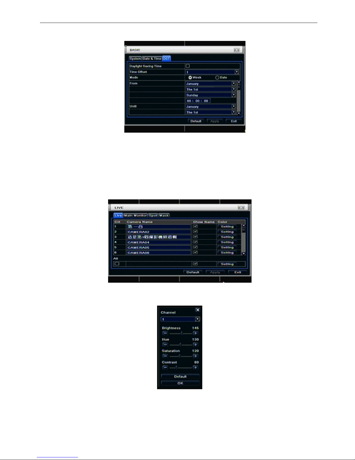
3.1.3 DST
Step1: enter into system configurationÆbasic configurationÆDST; refer to Fig 4-5:
Fig 4-5 basic configuration-DST
Step2: in this interface, enable daylight saving time, time offset, mode, start & end month/week/date, etc.
Step3: click “default” button to resort default setting; click “apply” button to save the setting; click “exit” button
to exit current interface.
3.2 Live configuration
Live configuration includes four submenus: live, host monitor, SPOT and mask.
3.2.1 Live
In this interface, user can setup camera name, adjust colors: brightness, hue, saturation and contrast.
Step1: enter into system configurationÆlive configurationÆlive; refer to Fig 4-6:
Fig 4-6 live configurationÆlive
Step2: tick off camera name; click “setting” button, a window will pop-up as Fig 4-7:
Fig 4-7 live-color adjustment
Step3: in this interface, user can adjust brightness, hue, saturation and contrast in live; click “default” button
to resort default setting, click “OK” button to save the setting.
Step4: user can setup all channels with same parameters, tick off “all”, then do relevant setup.
Step5: click “default” button to resort default setting; click “apply” button to save the setting; click “exit” button
to exit current interface.
14
3.2.2 Main monitor
Step1: enter into system configurationÆlive configurationÆhost monitor; refer to Fig 4-8:
Fig 4-8 live configuration-host monitor
Step2: select split mode: 1×1、2×2、2×3、3×3、4×4 and channel
Step3: dwell time: the time interval for a certain dwell picture display switching to next dwell picture display
Step4: selected the split mode, then setup current picture group. Click
button to setup the previous
channel groups of dwell picture, click
button to set the latter channel groups of dwell picture.
Step5: click “default” button to resort default setting; click “apply” button to save the setting; click “exit” button
to exit current interface.
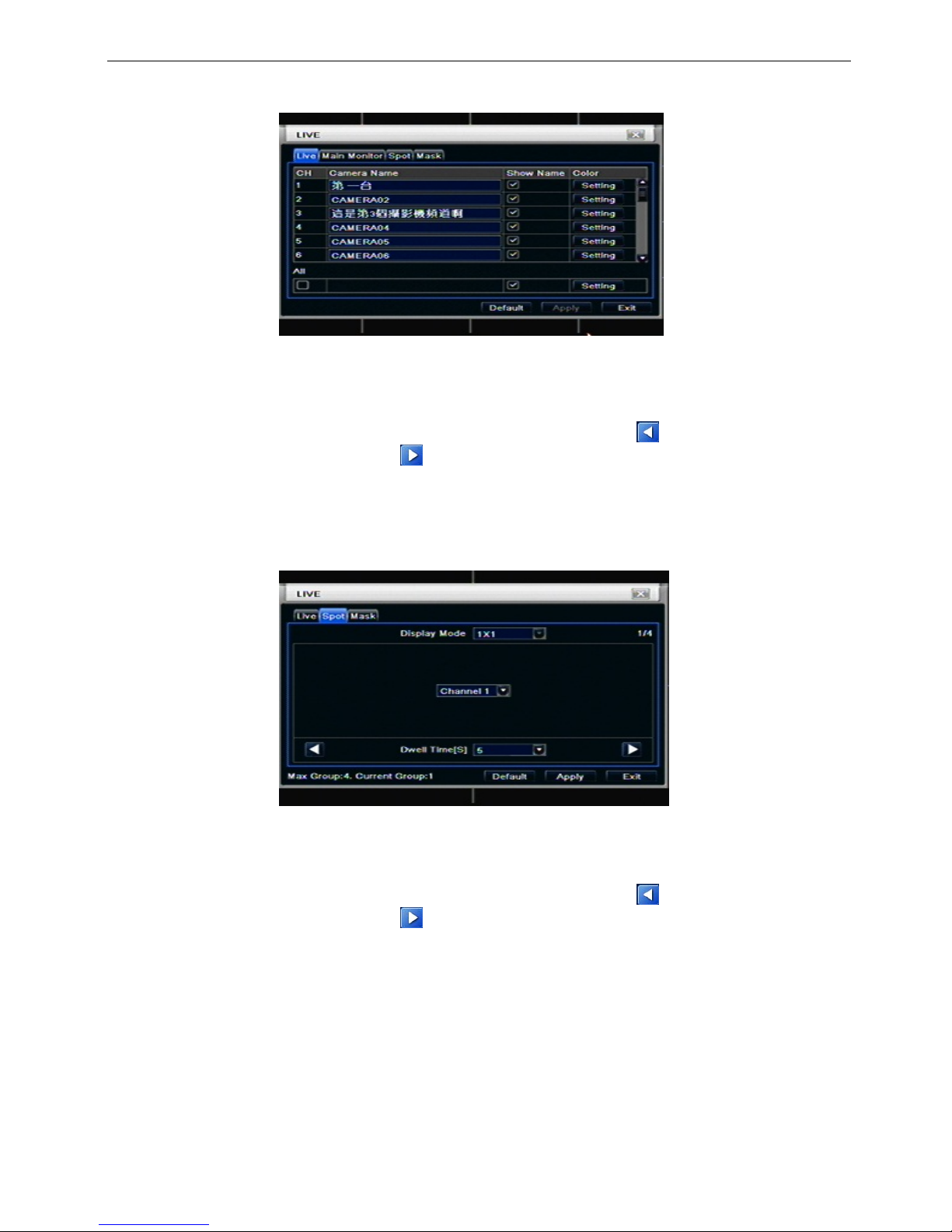
3.2.3 SPOT
Step1: enter into system configurationÆlive configurationÆSPOT; refer to Fig 4-9:
Fig 4-9 live configuration-SPOT
Step2: select split mode: 1×1and channel
Step3: dwell time: the time interval for a certain dwell picture display switching to next dwell picture display
Step4: selected the split mode, then setup current picture group. Click
button to setup the previous
channel groups of dwell picture, click
button to set the latter channel groups of dwell picture.
Step5: click “default” button to resort default setting; click “apply” button to save the setting; click “exit” button
to exit current interface
15
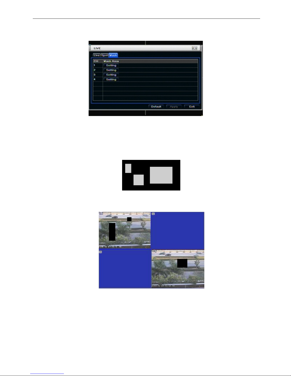
3.2.4 Mask
User can setup private mask area on the live image picture, max threes areas.
Fig 4-10 live configuration-mask
Setup mask area: click Setting button, enter into live image to press left mouse and drag mouse to set mask
area, refer to below picture. Click Apply button to save the setting.
Delete mask area: select a certain mask area, click left mouse to delete that mask area, click Apply button to
save the setting.
Setup mask area
Notice: The mask area will not be recorded on DVR. Please use this function carefully.
Live image mask area
16
3.3
Record configuration
Record configuration includes five sub menus: enable, record bit rate, time, recycle record and stamp.
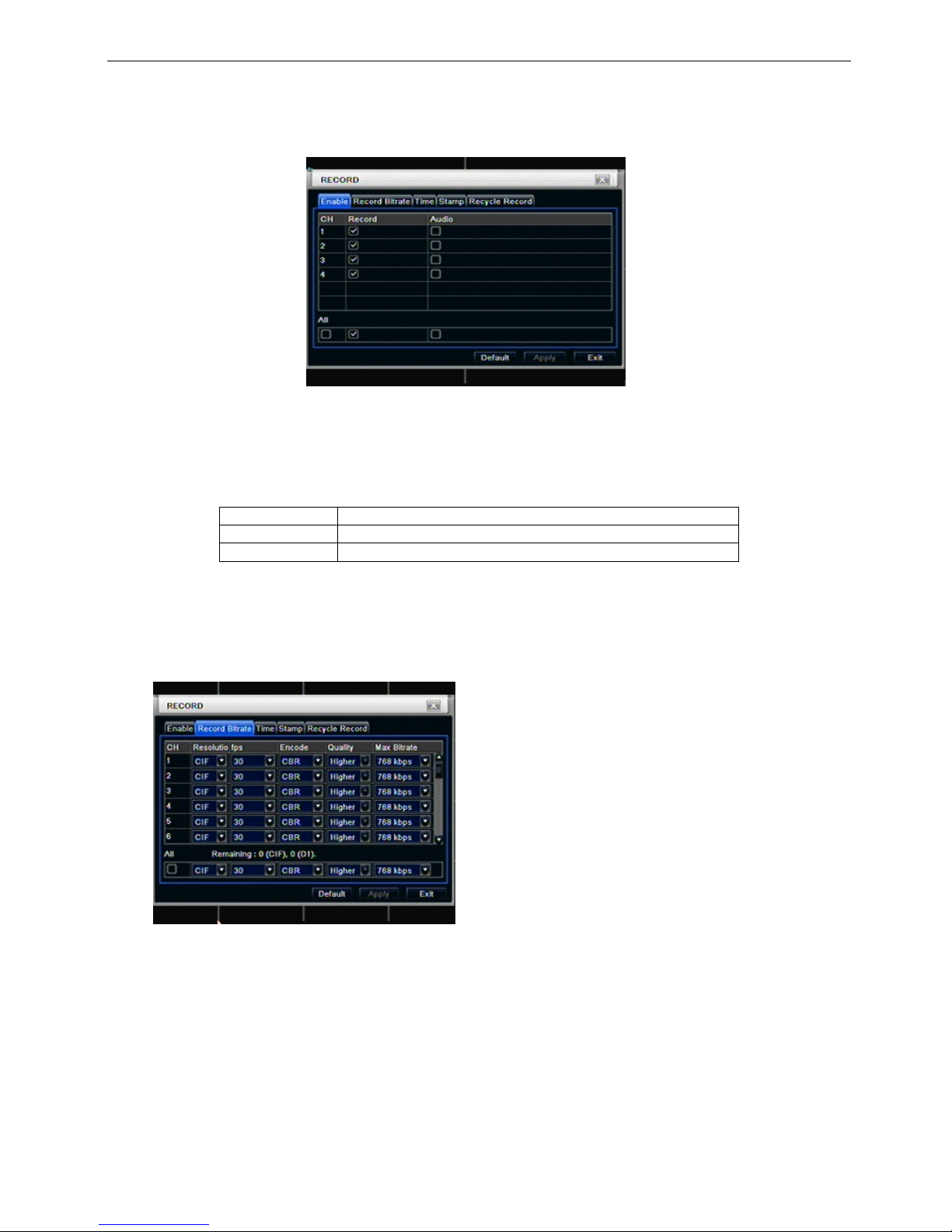
3.3.1 Enable
Step1: enter into system configurationÆrecord configurationÆenable; refer to Fig 4-11:
Fig 4-11 record configuration-enable
Step2: tick off record, audio and record time
Step3: user can setup all channels with same parameters, tick off “all”, then to do relevant setup.
Step4: click “default” button to resort default setting; click “apply” button to save the setting; click “exit” button
to exit current interface.
Definitions and descriptions of Record:
Parameter Meaning
Record Record switch of every channels
Audio Enable live record audio
3.3.2 Record stream
Step1: enter into system configurationÆrecord configurationÆrecord bit rate; refer to Fig 4-10:
16CH
Fig 4-10 record configuration-record bit rate
Step2: setup rate, resolution, quality, encode and max bit stream
Step3: user can setup all channels with same parameters, tick off “All”, then to do relevant setup.
Step4: click “default” button to resort default setting; click “apply” button to save the setting; click “exit” button
to exit current interface.

17
Note: if the rate value set is over high the maximum resources of the device, the value will be
adjusted automatically.
Definitions and descriptions of Record stream:
Parameter Meaning
Rate
Range from: 1-30(NTSC)1-25(PAL)
Resolution Support CIF and D1
Quality The quality of recorded images. The higher the value is, the
clearer the recorded image is. Six options: lowest, lower,
low, medium, higher and highest.
Encode VBR and CBR
Max bit stream
Range from: 64 Kbps、128 Kbps、256 Kbps、512 Kbps、
768 Kbps、1Mbps、2 Mbps
3.3.3 Time
Step1: enter into system configurationÆrecord configurationÆ time; refer to Fig 4-12:
Fig 4-12 record configuration-time
Pre-alarm record time: the record time before event happen i.e. record time before motion detection or
sensor alarm is triggered.
Post-alarm record: set the post recording time after the alarm is finished, five options: 10s、15s、20s、30s
and 60s.
Expire time: the hold time of saved records. If the set date is overdue, the record files will be deleted
automatically.
Step2: user can setup all channels with same parameters, tick off “all”, then to do relevant setup.
Step3: click “default” button to resort default setting; click “apply” button to save the setting; click “exit” button
to exit current interface.
18
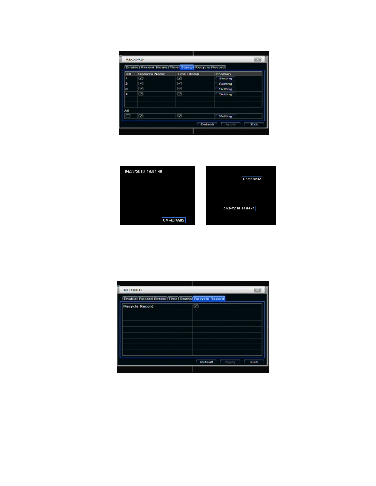
3.3.4 Stamp
Stamp:User can overlap the channel name and time stamp on video.
Step1: enter into system configurationÆ record configurationÆ stamp; refer to Fig 4-13:
Fig 4-13 record configuration-stamp
Step2: tick off camera name, time stamp; click Set button, user can use cursor to drag the camera name and
time stamp in random positions, refer to below Figures:
Before drag after drag
Step3: user can setup all channels with same parameters, tick off “all”, then to do relevant setup.
Step4: click “default” button to resort default setting; click “apply” button to save the setting; click “exit” button
to exit current interface.
3.3.5 Recycle record
Step1: enter into system configurationÆrecord configurationÆrecycle record;
Step2: tick off recycle record, the recycle record function will enable, it will cover the earlier recorded files
and keep recoding when HDD is full; if disenable this function, it will stop recording when HDD is full.
Step3: click “default” button to reset default setting; click “apply” button to save the setting; click “exit” button
to exit current interface.
 Loading...