

Pamex FKL User Manual


WARNING
CAUTION !
1
IMPORTANT SAFETY INSTRUCTION
1. To prevent damage to the finish, DO NOT use any abrasives, sharp objects or harsh chemical
products containing alcohol, petroleum solvents, acids or acetone to clean this lockset.
2. To prevent damage to the sensitive electronic components, DO NOT allow any liquids to enter
lockset while installing or cleaning.
1. Do not attempt to disassemble any internal components of this lockset as this WILL void the
limited warranty.
2. Do not drop or hit /strike the lockset as excessive shock may result in permanent damage.
STRONGLY recommended that you always create a written backup of the programming code
and individual user codes. Please use the last page of this booklet as your reference.
5. For your Security, please remember to change this lockset's factory default programming code
to a PERSONAL programming code prior to normal day to day use of this product (See Page 28).
6. It is STRONGLY recommended that you use only ALKALINE BATTERIES to operate this product.
3. Do not use sharp objects to press key buttons.
4. It is

CONTENTS
INSTALLATION INSTRUCTIONS
1. COMPONENTS
3. LATCH INSTALLATION
4. STRIKE PLATE INSTALLATION
5. LEVER DIRECTION DETERMINATION
7-1. MOUNTING EXTERIOR ASSEMBLY
7-2. PREPARING TO MOUNT INTERIOR ASSEMBLY
7-3. REMOVING DECORATIVE COVER
7-4. MOUNTING INTERIOR ASSEMBLY
7-5. BATTERY INSTALLATION
7-6. REINSTALL LEVER
8-1. EXCHANGE OF LEVER
8-2. EXCHANGE OF LEVER (REMOVAL OF INSIDE LEVER)
8-3. EXCHANGE OF LEVER (REMOVAL OF OUTSIDE LEVER)
2. DOOR PREPARATION
6
2
TEMPLATE
5
6-1. TO RESET DIRECTION OF INSIDE LEVER
6-2. TO RESET DIRECTION OF OUTSIDE LEVER
8-4. SWAP INSIDE AND OUTSIDE LEVERS (REMOVAL OF CYLINDER)
8-5. SWAP INSIDE AND OUTSIDE LEVERS (ASSEMBLE OUTSIDE LEVER)
8-6. SWAP INSIDE AND OUTSIDE LEVERS (ASSEMBLE INSIDE LEVER)

CONTENTS
MAIN OPERATING INSTRUCTIONS
SETUP MODE
1. CHANGE PROGRAMMING CODE
2. ADD A USER CODE
3. DELETE INDIVIDUAL EXISTING USER CODE
5. DISABLE ALL THE EXISTING USER CODES (VACATION MODE)
6. DISABLE BUTTON SOUND (MUTE MODE)
7. SETTING AUTO-LOCK TIME DELAY
8. RESTORE FACTORY SETTING
OPERATION MODE
TROUBLESHOOTING GUIDELINE
DATA RECORDS
4. DELETE ALL THE EXISTING USER CODES AT ONCE
3
DECLARATION AND SAFETY STATEMENTS
1.TO ACTIVATE AUTO-LOCKING (AUTOMATIC RE-LOCKING)
2. TO OPEN (UNLOCK) THE DOOR
3. TO DEACTIVATE AUTO-LOCKING (AUTOMATIC RE-LOCKING)
4
A
B
C
D
E
F
G
H
I
J
K
L
M
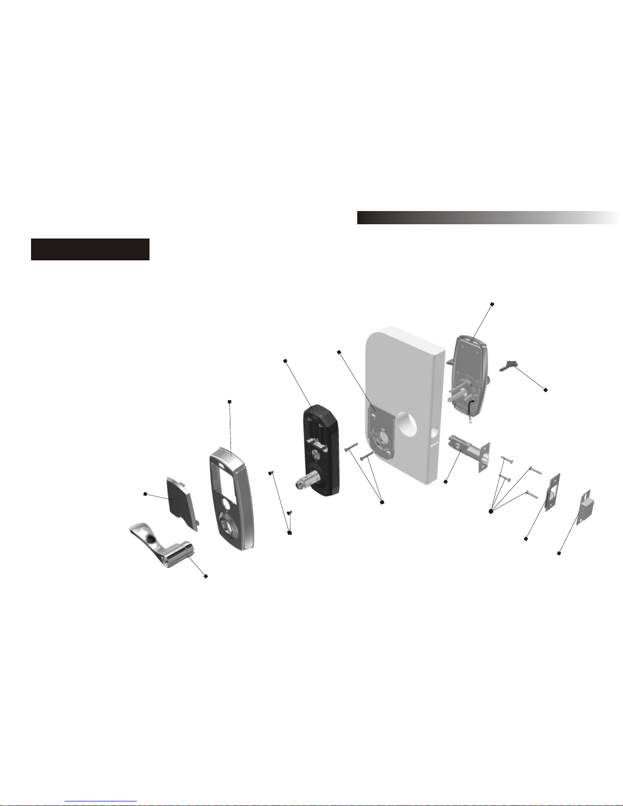
INSTALLATION INSTRUCTIONS
A. Key
B. Exterior Assembly
C. Mounting Plate
D. Interior Assembly
E. Decorative Cover
F. Battery Pack Cover
G. Lever
H. 5/16''(7.8mm) Screw (2)
I. 1-1 /4'' (32mm) Screw (2)
J. Latch
K. 6/8''(19.2mm) Wood Screw (4)
L. Strike
M. Dust Box
1. COMPONENTS
5
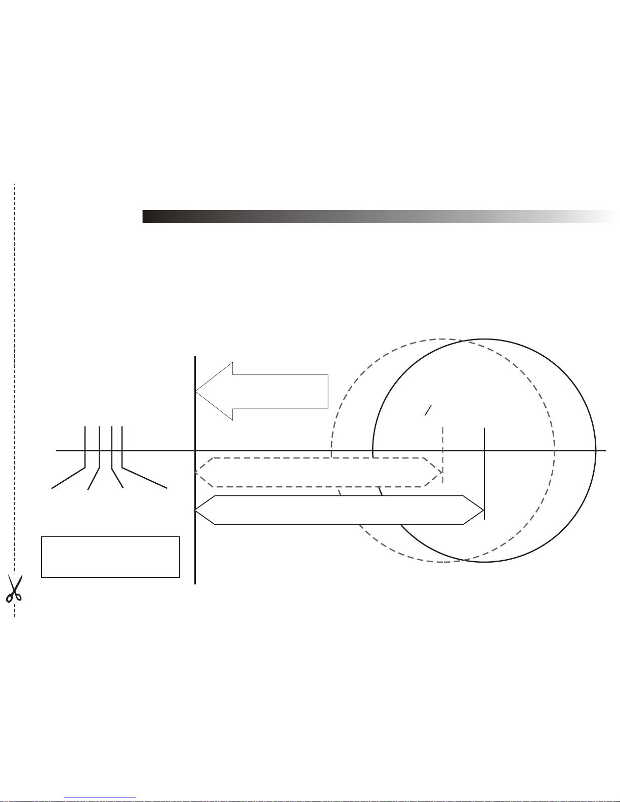
Fold here
Place on door edge
51 45 40 35
Drill 1''(25mm) hole
at center of door edge
2''
1-3/4''
1-9/16''
1-3/8''
O54mm(2-1/8'')
Backset 70mm(2-3/4'')
Backset 60mm(2-3/8'')
1. Remove lever lock, or do not install lever lock prior to painting your door.
2. Do not let any water or liquid into the lockset during installation process.
TEMPLATE
IMPORTANT BEFORE PROCEEDING
NOTE:MEASUREMENTS BELOW ARE JUST A GUIDELINE. Please measure your door to determine
the exact center of your door edge.

6
54mm(2-1/8'')
25mm(1'')
60mm(2-3/8'') or 70mm(2-3/4'')
A B
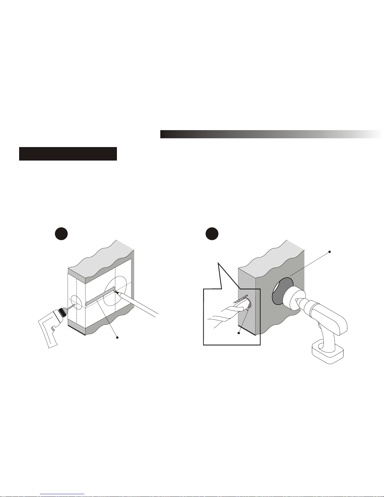
DOOR PREPARATION
2. DOOR PREPARATION
Use Diagram of spade bit
here and not Drill bit
NOTE: If replacing an existing lock or installing in a pre-drilled door, begin with page 7.
Fold the template against the door edge as shown in below illustration, mark and drill a pilot
hole for latch on door edge, select backset (60mm or 70mm) to mark and drill a pilot hole for
selected backset on door face. (It is recommended to mark centerline of the hole on door about
36 inches (914mm) above the floor. )
7
60mm(2-3/8'')
70mm(2-3/4'')
INSTALLATION INSTRUCTIONS
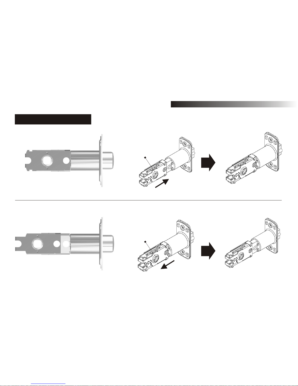
3. LATCH INSTALLATION
A. Pull the drive-shaft backward for adjustment to 70mm(2-3/4'').
B. Push the drive-shaft forward for adjustment to 60mm(2-3/8'').
Drive-shaft
Drive-shaft
8
INSTALLATION INSTRUCTIONS
A. Insert the latch into the latch hole. Using the faceplate as a pattern, TRACE a line along the out
edge of the faceplate and chisel a 4mm (1/8") slot in the marked out area. Face plate should fit
flush with door edge.
B. Insert the latch into the latch hole and fasten with screws.
Show pencil marking outer edge of latch faceplate with Dotted lined
directional arrows as you do not just carve out the screw holes
A B
3. LATCH INSTALLATION
9
INSTALLATION INSTRUCTIONS
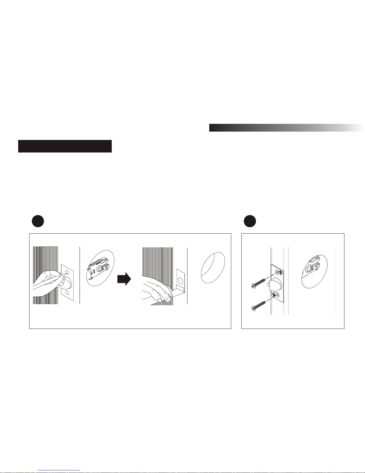
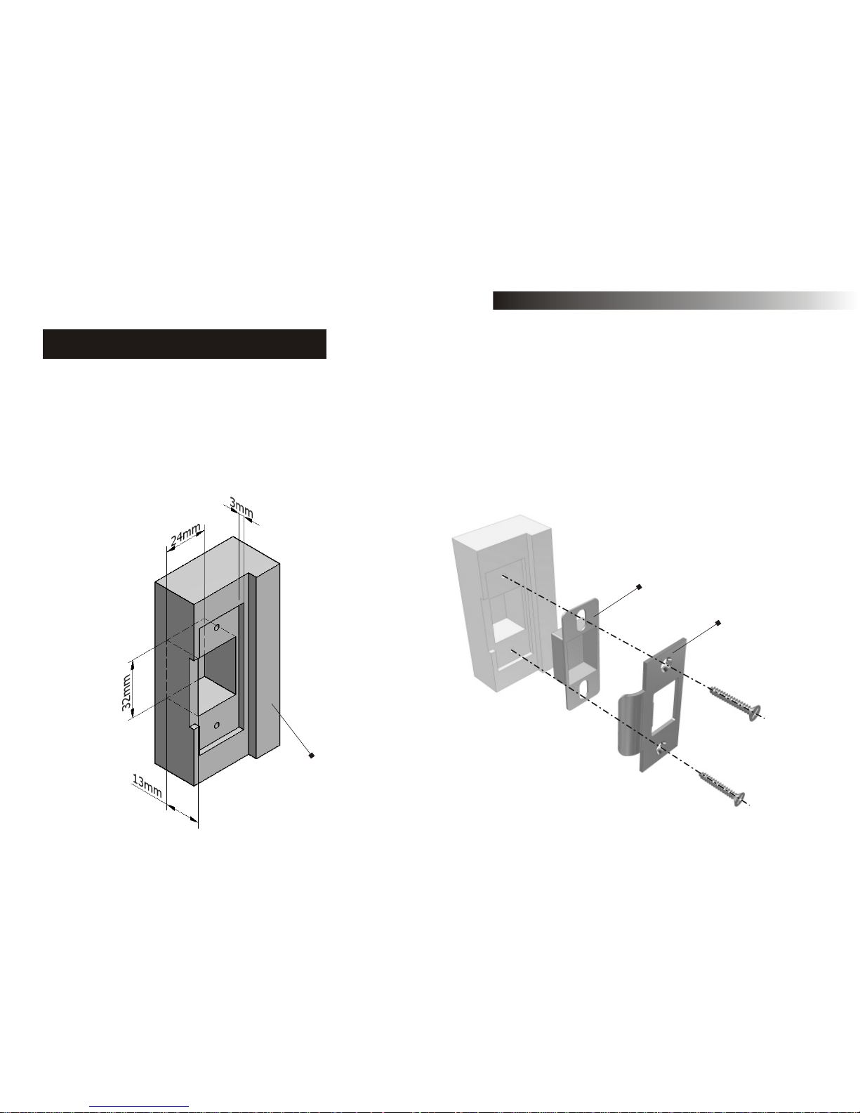
4. STRIKE PLATE INSTALLATION
A. Placing the strike plate on the door frame, TRACE a line along the out edge of the strike plate
and chisel a 3mm (1/8") slot in the marked out area.
B. Chisel out a hole measuring 32 x 24 x 13mm (1-1/4''X1''X1/2'') in association with the size of the
dust box.
C. Fasten the strike and dust box with screws.
Door frame
Strike
Dust box
INSTALLATION INSTRUCTIONS
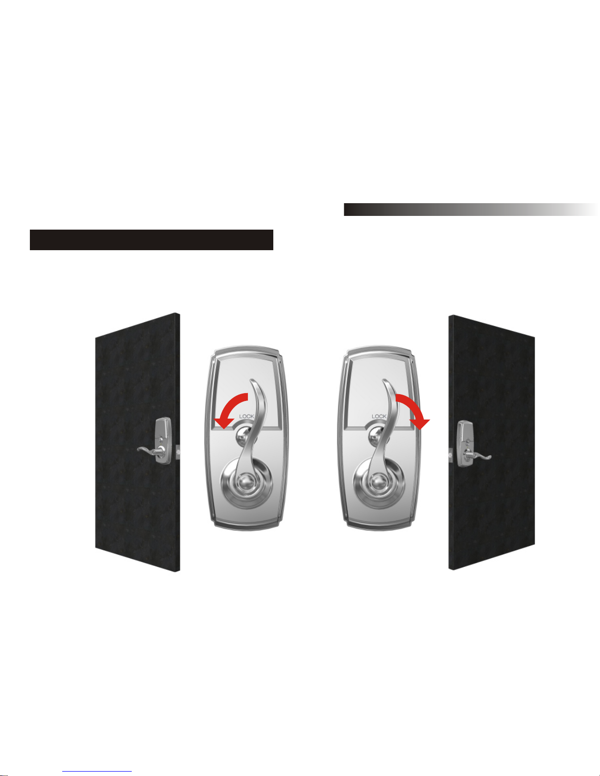
5. LEVER DIRECTION DETERMINATION
NOTE: Do not install the lock when the lever is at vertical position.
Before lock installation, please determine the inside lever direction according to the opening
direction of door as shown.
10

11
INSTALLATION INSTRUCTIONS
NOTE: Do not install the lock when the lever is at vertical position.
Before lock installation, please determine the outside lever direction according to the opening
direction of door as shown.
5. LEVER DIRECTION DETERMINATION
 Loading...