


AM/FM Power Set Procedure
For AM or FM power levels must be adjusted in that mode.
For AM mode set carrier no higher than 275 Watts. AM
requires peak power of 4 times carrier level.
TROUBLESHOOTING
Transmit Fault Indications
Bypass SWR: [as seen on display]
Amp is in BYPASS to protect from high SWR. This
indication shows up whenever SWR is, (or has been) over
2.5:1 during a transmission. Transient faults such as
antenna arcing can show a low SWR after the fault event,
while transmitter is still keyed up.
Bypass TEMP: [as seen on display]
Amp is in BYPASS to protect from high temperature.
Temperature will show in red when temperature exceeds
71 degrees C. When the heatsink temperature exceeds
100 degrees C. “Bypass Temp” will show on the display.
(Amplier locked in Bypass)
Solution:
Allow time for the heatsink to cool down to below 70
degrees C.
Operate mode will automatically return. Verify that
nothing is blocking proper airow through the side
vents.
Solution:
1) Make sure correct LA-1K antenna connector is
selected.
2) Verify that your HF-AUTO or other tuner has obtained
a good match while amp is in standby. Attempting Auto
tuning at high power can cause this “Bypass SWR” alert.
With some autotuners it may be necessary to select
manual mode after obtaining a low SWR to prevent
unwanted tuning in the middle of your transmission.
3) If antenna arcing or loose connection is suspected,
try the amplier on a dummy load. If it works normally,
there is likely some type of intermittent SWR problem.
Note: High SWR, or prolonged transmission in carrier
modes, may cause elevated temperature.
Bypass+VD: [as seen on display]
Amp is in BYPASS to protect from loss of +50V, drain
voltage supply. The indication should clear in a few
seconds. This occurs when operating on 120V, if Drain
Current (Id) exceeds 32 Amps.
Solution:
Switch supply voltage to 240V, or If operating on 120V,
Reduce Drive Power.
PALSTAR

TX Wait: [as seen on display]
This shows on display when the PTT Line is grounded but
NO RF is present. RF must be applied with PTT line low
to key the amplier to the transmit state.
Other Issues:
Won’t amplify or autoband switch when transmitting.
Solution:
Make sure that the PTT cable is connected to the
transceiver. This is a REQUIRED connection. Note that
“TX” will show on display whenever the PTT connector
sees a ground. Some transceivers must have their PTT
keying output enabled in the transceiver’s menu
settings.
Low SWR on transceiver, high SWR on LA-1K
This problem arises when you observe Low SWR on
transceiver, but the LA-1K shows High SWR.
Solution:
Always disable (i.e. Bypass) the autotuner in your
transceiver when driving any amplier.
The transceiver’s autotuner can not match loads
connected to the amplier’s output.
PALSTAR

Palstar products are designed by
Hams for Hams carrying on the
Palstar tradition for high-quality
products designed and
manufactured in Ohio, USA.
LA-1K RF SENSING 1000W
DUAL HF LDMOS AMPLIFIER
1000 watts PEP CW ICAS (160 m to 6m)
RF Sensing Auto Band Switching
Color TFT touch screen
Variable speed fans
12.75” x 6.25” x 16.5”
Weight: 27 lbs, 12.3 Kg
PALSTAR
LA-1K RF SENSING 1000W
DUAL HF LDMOS AMPLIFIER
Technical Manual
9676 N. Looney Rd,
Piqua, OH 45356 USA
(937) 773-6255
(800) 773-7931
(937) 773-8003 (Fax)
www.palstar.com
PALSTAR
Designed and Manufactured in the USA
Copyright 2018 Palstar, Inc.

LA-1K SPECIFICATIONS
THEORY OF OPERATION
SSB POWER: Power levels up to 1000 Watts PEP
CW MODE: 1000 Watts CW ICAS
FM/RTTY: 500 watts
AM: 275 watts
FREQUENCY RANGE: 1.8 TO 54 MHz
DISPLAY: Color TFT touch screen
INPUT DRIVE LEVEL: 45W - 55W (All Bands) 40-55W (Typical)
OUTPUT: 3 x RF SO-239 or Type N
ALC: Exciter power control
GAIN: 13dB + or -1dB (nominal)
RF SENSING: Auto Band Switching without Band Data
Cable from transceiver
RF OUTPUT: Vacuum RELAY T/R Switching
POWER SUPPLY: Internal Medical grade
AC POWER: 100-125VAC 15A or 200-250VAC 10A
DC SUPPLY: 50VDC @42A
POWER DEVICES: 2 x 5600H 600W LDMOS
AUTO-PROTECT: SWR/Short Circuit/Over Temp
COOLING: Variable Speed Fans (3 speed)
INTERMOD: Low IMD Distortion >-35dB
PURE SIGNAL: Sample@+10dBm @1kW ouput (Rear Panel)
CHASSIS: .090 ga. aluminium
TOP COVER: .090 ga. aluminium, powder coated
DIMENSIONS: 12.75” W x 6.25“ H x 16.5” D
WEIGHT: 27 LBS, 12.25 Kg
DESIGN CONCEPT: Full compatibility with Palstar
HF-AUTO autotuner
WARRANTY: Two year
The LA-1K RF Sensing Dual HF LDMOS amplier is a complete
stand-alone amateur RF LINEAR amplier.
It is completely independent of data from an external source to
determine frequency for tracking from Band to Band. As a result of this
feature, the LA-1K will function with any transmitting device without
interconnecting data cable attachments.
The power output of the LA-1K is 1000 Watts PEP CW ICAS (Intermittent
Commercial and Amateur Service). Under the ICAS classication, the
use of the LA-1K is designed for transmissions that are of an
intermittent nature.
Intermittent operation of the LA-1K implies that no operating or
“ON” period of 1000W of Continuous Carrier Power will exceed
approximately 1(ONE) minute. On Single Side Band (SSB) voice
duty there is no limit on transmit time at full power of 1000W PEP.
Every “on” period must be followed by an “o” or standby period of at
least the same or longer duration. The LA-1K provides a +10dBm@1kW
RF tap feed at the rear panel to provide provisions for “PURE SIGNAL”
operation provided by compatible transceivers. The level adjustment
is calibrated at the factory. The LA-1K was designed to be fully
compatible with the Palstar HF-AUTO automatic antenna tuner.
Included with the LA-1K:
• Two (2) line cords for 110VAC and 220VAC
• User Manual
• Amplier unit
• Shipping box (please keep box for warranty repair, etc.)
As per FCC 15.21 changes or modications not expressly approved
by Palstar could void the user's authority to operate the
equipment. No tune up procedure exists.
Page 1
PALSTAR

SCREEN DISPLAY ON POWER-UP
ON INITIAL POWER-UP
Display will indicate STBY mode (stand-by). To switch
mode press the “MODE” button on the touchscreen
display to switch into “OPR” mode (operational).
To change default POWER UP MODE push MENU then
NEXT until SELECT POWER UP MODE displays at the top.
Now select desired POWER UP MODE, STANDBY, or LAST
USED, or OPERATE.
STAND-BY MODE OPERATIONAL MODE
TRANSMITTING
OPERATIONAL MODE
OPERATIONAL MODE
To switch into Operational mode “OPR” press the “MODE”
button on the touchscreen display. The touchscreen
menu will display “OPR” mode (operational). The red
power bar graphical indicator will only be visible when
transmitting.
OPERATIONAL MODE
NOTE: Wattmeter only shows RED power bar graphical
indicator when the LA-1K is producing power.
It is recommended that for power up mode “STBY” is
selected to allow a TUNE sequence when using our
HF-AUTO Antenna Tuner. After the HF-AUTO is tuned,
push MODE to select “OPR” for operation mode.
Page 2
ADDITIONAL FEATURES
Automatic band selection when user transmits
Automatic antenna selection of last used antenna output when
bands selected
Over temperature protection by fan speed control, and bypass
mode if temperature exceeds 100° C (fault temperature shows on
display)
Unit is locked in Bypass until temperature drops below 70°C
Frequency operation lock-out from 25.99MHz - 28.00MHz
Also see Page 5 and Rear Panel on Page 15.
PALSTAR

OPERATIONAL MODE
BAND SELECT
To switch bands, 160M-80M-40-30M-20-15M-12-10M-6M,
press the “BAND” button on the touchscreen display,
then select desired band. The LA-1K selects the proper
band automatically when transmit (PTT) is activated.
Select the BAND by pressing the corresponding numbers
on the touchscreen display. A yellow arrow below the
number of the BAND will indicate which BAND is
selected. Press EXIT to return to main menu.
ANTENNA SELECT
To switch antennas between ANT 1(Coax 1), ANT 2 (Coax
2), and ANT 3 (Coax 3), press the “ANT” button on the
touchscreen display.
Then select desired antenna ouput. This setting will
automatically select when changing bands to the last
one used on any particular band. The default value is
ANT 1.
SELECT BAND
Select the antenna by pressing the corresponding
number on the touchscreen display. A yellow arrow
below the number of the antenna will indicate which
antenna is selected. Press EXIT to return to main menu.
Page 3
PALSTAR
OTHER MENU OPTIONS
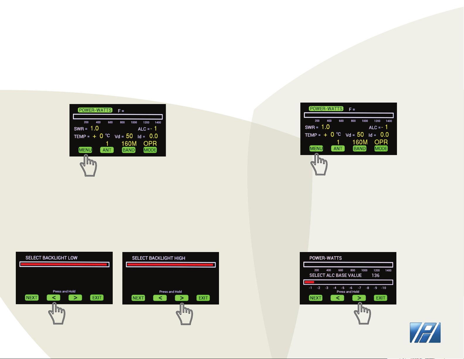
SELECT BACKLIGHT
To adjust the backlight on the touchscreen display press
MENU.
Press and hold the < or > arrows to adjust BACKLIGHT
LOW (screen intensity when no buttons are pressed) and
select NEXT and then < or > arrows to adjust BACKLIGHT
HIGH (screen intensity when buttons are being pressed).
SELECT BACKLIGHT LOW/HIGH
SELECT ALC BASE VALUE
To adjust ALC base value select menu on the touchscreen
display.
Press and hold the < or > arrows to increase or decrease
ALC BASE VALUE. If using ALC this should be adjusted
carefully to match your transceiver’s requirements.
ALC BASE VALUE
Page 4
PALSTAR

SSB POWER SET PROCEDURE
SSB
Power set procedure for SSB (see below for AM/FM)
1) Place transceiver in CW or RTTY (NOT AM or FM).
2) With LA1K in standby mode, key the transceiver and
set for initial power level of about 30 watts, then unkey
transmitter.
3) Switch the LA1K to Operate mode. Transmit and adjust
transmitter output to achieve desired output power
level. Do no exceed 1000 Watts output, or 60 Watts drive
power (to avoid splatter). UNKEY TRANSMITTER.
4) Switch to desired operating mode. The peak power will
be the same as it was on carrier mode, even though many
wattmeters do not provide correct peak
readings on SSB signals.
ALC ADJUSTMENT PROCEDURE
ALC
Suggested adjustment procedure for ALC
NOTE: Amplier ALC is only used for SSB Voice
transmission.
1) Connect ALC cable from transceiver to LA-1K amplier.
2) Set ALC Base Value to Zero on amplier.
3) Place transceiver in CW or RTTY (NOT AM OR FM).
4) With LA-1K in standby mode, set transceiver fo initial
power level of about 30 Watts, then unkey transmitter.
5) Switch the LA-1K to Operate Mode. Transmit and
adjust transmitter output, to achieve desired output
power level. Do not exceed 1000 Watts output, or 60
Watts drive power (to avoid splatter). UNKEY
TRANSMITTER.
6) Switch transciever to LSB or USB transmission.
Transmit speaking in microphone and adjust the LA-1K
ALC base value increasing the ALC voltage until the
power output starts to drop. The point where power
drops slightly is the correct setting. Push EXIT on
LA-1K.
More precise adjustments may be made by connecting
an oscilloscope to observe the output for clipping.
Page 5
PALSTAR

PREVENTING DAMAGE TO LA-1K
WARNING TO PREVENT DAMAGE
1. Never drive input power in excess of 60 Watts.
2. Never use a tuning pulser in CW full break-in mode.
The LA-1K was NOT designed for full break in CW
operation.
Very high speed full break in keying which toggles the
PTT line can lead to amplier damage.
3. Never block the air vents of the LA-1K. Without
proper airow, excess heating of internal components
may occur.
REQUIRED CONNECTIONS:
Rear Panel RF Deck Front Panel
Page 6
AC input lter
+/-12V (BIAS)
+50V@42A
Power Supply
Dual output
lters
PALSTAR

EXTERNAL DATA CONNECTORS
Table of YAESU/ELECRAFT
Band selections and
4 bit BCD codes
Band DCBA
60m 0000
160m 0001
80m 0010
40m 0011
30m 0100
20m 0101
17m 0110
15m 0111
12m 1000
10m 1001
6m 1010
NC 1111
0 = low voltage (0 volts)
1 = high voltage (5 volts)
MARS Frequency Usage:
Range: 2.011 - 25.401 MHz
Power Level: 400 Watts
Emissions: 3K00J3E/J2D
Table of ICOM Band and
Voltage Level
NC 12 volts
160m 7.0-8.0 volts
80m 6.0-7.0 volts
40m 5.0-6.0 volts
30m 0.0-1.0 volts
20m 4.0-5.0 volts
17/15m 3.0-4.0 volts
12/10m 2.0-3.0 volts
6m 1.0-2.0 volts
Pin 5
The LA-1K automatically selects bands and it is normally NOT
necessary to connect band data cables between your transceiver and
the LA-1K amplier.
RADIO INTERFACE CONNECTOR:
This connector is designed to be
pin for pin compatible with other
ampliers. The required cables are
widely available. They can be used
to connect to ICOM and YAESU
transceivers.
XCVR Interface
[Radio Interface Pin Out]
Pin Function
1 BCD B IN
2 BCD A IN
3 Kenwood RX (data in) [custom cable required]
4 Kenwood TX (data out) [custom cable required]
5 Icom Band Data
6 GND
7 Amp-Key IN
8 BCD D IN
9 BCD C IN
Page 7
RS232 BAND CONTROL CONNECTOR:
This connector is designed to be used with Kenwood transceivers for
band selection using a null modem adapter. It is also designed to
control the amplier from a computer.
PALSTAR

HOW-TO UPDATE FIRMWARE
DOWNLOADING LA-1K FIRMWARE
CREATE a folder on your computer’s hard drive
NAME the folder LA_1KFIRMWARE
DOWNLOAD the Firmware le (Zip format) from the Palstar website,
http://www.palstar.com/en/la-1k/. The download link is near the bottom of
the page. The link to the le is named “LA-1K Firmware x.x”
SAVE the le to the folder you created in Step 1
OPEN the folder by right-clicking on the Zip le and select “Extract All” -
follow the steps in the Extraction wizard
CONNECT one end of the USB cable to a USB port on your computer.
LA-1K FIRMWARE SUMMARY
SEE WEBSITE FOR FIRMWARE SUMMARY:
http://www.palstar.com/en/la1k/
POWER SUPPLY PERFORMANCE
If the LA-1K is used on 120VAC the max current rating is
33A. The DRIVE LEVEL on some of the bands may need to
be reduced.
DOUBLE-CLICK “LOAD_LA-1K” within your LA_1KFIRMWARE folder that you
created in Step 2.
Follow the instructions on the opened computer window and use the
"Browse" button to select the rmware version to be loaded.
Depress and hold down the GREY button to the right of the USB port
labeled “PROGRAM UPDATES” during the next two steps.
CONNECT the other end of the USB cable to a USB cable to the LA-1K front
panel. A "Found 1 device" message will appear on the right side of the
opened computer window.
TURN-ON the LA-1K.
Release the GREY button on the LA-1K front panel.
Click on the "Update Firmware" button that is on the opened computer
window. Wait until the green bar in the middle of the computer window
shows that the programming completes by lling from left to right. The
rmware version number on the LA-1K is on the bottom line of the start up
screen.
If the current exceeds 33 Amps, the power supply will
shut down and the Vd reading on the TFT display will
read ZERO; “BYPASS + Vd” shows on display;
(operation@120 VAC).
The power supply will immediately come back on in 1 to
2 seconds and the display will read 50V again. Reducing
drive will prevent this from occuring.
The medical grade power supply will not be damaged as
this feature has been designed into the power unit of
the LA-1K.
For 230-250 VAC operation at full power of 1000W PEP is
available on all bands. It is recommended that 240VAC
be used for all modes.
Page 8
PALSTAR

AM/FM Power Set Procedure
For AM or FM power levels must be adjusted in that mode.
For AM mode set carrier no higher than 275 Watts. AM
requires peak power of 4 times carrier level.
TROUBLESHOOTING
Transmit Fault Indications
Bypass SWR: [as seen on display]
Amp is in BYPASS to protect from high SWR. This
indication shows up whenever SWR is, (or has been) over
2.5:1 during a transmission. Transient faults such as
antenna arcing can show a low SWR after the fault event,
while transmitter is still keyed up.
Solution:
1) Make sure correct LA-1K antenna connector is
selected.
2) Verify that your HF-AUTO or other tuner has obtained
a good match while amp is in standby. Attempting Auto
tuning at high power can cause this “Bypass SWR” alert.
With some autotuners it may be necessary to select
manual mode after obtaining a low SWR to prevent
unwanted tuning in the middle of your transmission.
Bypass TEMP: [as seen on display]
Amp is in BYPASS to protect from high temperature.
Temperature will show in red when temperature exceeds
71 degrees C. When the heatsink temperature exceeds
100 degrees C. “Bypass Temp” will show on the display.
(Amplier locked in Bypass)
Solution:
Allow time for the heatsink to cool down to below 70
degrees C.
Operate mode will automatically return. Verify that
nothing is blocking proper airow through the side
vents.
Note: High SWR, or prolonged transmission in carrier
modes, may cause elevated temperature.
Bypass+VD: [as seen on display]
Amp is in BYPASS to protect from loss of +50V, drain
voltage supply. The indication should clear in a few
seconds. This occurs when operating on 120V, if Drain
Current (Id) exceeds 32 Amps.
3) If antenna arcing or loose connection is suspected,
try the amplier on a dummy load. If it works normally,
there is likely some type of intermittent SWR problem.
Page 9
Solution:
Switch supply voltage to 240V, or If operating on 120V,
Reduce Drive Power.
PALSTAR

TROUBLESHOOTING
TX Wait: [as seen on display]
This shows on display when the PTT Line is grounded but
NO RF is present. RF must be applied with PTT line low
to key the amplier to the transmit state.
Other Issues:
Won’t amplify or autoband switch when transmitting.
Solution:
Make sure that the PTT cable is connected to the
transceiver. This is a REQUIRED connection. Note that
“TX” will show on display whenever the PTT connector
sees a ground. Some transceivers must have their PTT
keying output enabled in the transceiver’s menu
settings.
Low SWR on transceiver, high SWR on LA-1K
This problem arises when you observe Low SWR on
transceiver, but the LA-1K shows High SWR.
Solution:
Always disable (i.e. Bypass) the autotuner in your
transceiver when driving any amplier.
The transceiver’s autotuner can not match loads
connected to the amplier’s output.
NORMAL MODE LA-1K KEYING
Starting with Firmware V1.03H:
Added New Menu Option: “NORMAL or DIRECT KEYING”
In “NORMAL MODE” the amplier RF Sensing switches
bands automatically before relay keying occurs (as
follows):
When the transceiver keys, the amplier RF Sensing
MUST see RF to detect frequency and switch bands
before keying. It does NOT key up in “direct response”
to the PTT line but requires RF to be applied as well.
Each time the PTT line goes low, the amplier repeats
the same sequence again. Total time required is around
20 milli-seconds. During this time, the two relays
transition from receive, to transmit.
If operating on SSB mode, the rise time of the RF drive
is fairly slow, therefore this relay switching results in
very little reected RF power.
In some digital modes, (or full break-in CW), the RF
reaches full power just about instantly, so the relay
transition is seen as a 2.5 milli-second SWR spike (as the
2 relays transition from receive to transmit).
This is NOT harmful to modern transceivers, at only
40 Watts output. Direct Keying mode (Below) may be
selected to prevent this transient from occurring.
Page 10
PALSTAR

TYPICAL KEYING EXAMPLES
NORMAL MODE LA-1K KEYING
Transceiver Delay
0 ms
14 ms
PTT
LOW
RF
APPLIED
VALID
DETECTED
HOW KEYING WORKS:
1) The amplier won’t close its transmitting output relay
until it gets a solid frequency reading and switches
bands. This requires 14 milliseconds of RF being applied.
4 ms 2.5 ms
BAND
FREQ
OUTPUT
RELAY
CLOSED
INPUT
CLOSED
TOTAL DELAY
= 20.5 msec
HI-POWER
RF is now at
OUTPUT
DRIVE
RELAY
DIRECT MODE LA-1K KEYING
Transceiver Delay
2.5 ms
RELAY
PTT
LOW
4 ms
OUTPUT
CLOSED
Selection of “DIRECT KEYING” mode closes the LA-1K
transmit relays in direct response to the PTT line. This
way, the transceiver’s built in transmit RF delay ensures
enough time for the relays in LA-1K to be in transmit
position before RF is applied. Around 6 milli-seconds is
required for relay closing, so if adjustable, transceiver
keying delay should be set higher than 6 msec.
3.5 ms
INPUT
RELAY
CLOSED
TRANSCEIVER
APPLIES
RF
TOTAL DELAY
Before Transmit Available
= 10 ms approx.
HI-POWER
RF is now at
OUTPUT
Transceiever keying delay
set for 10 ms in this
example.
2) The output relay then closes requiring 4 milliseconds
to close. We are now at at 18 milliseconds.
3) The input relay now closes, (it was energized 2
milliseconds after the transmit relay) This adds 2.5
milliseconds delay. (Hi Power RF now appears at output).
Total delay is around 20.5 milliseconds.
Page 11
Please note: A band data cable is required in this
mode. The LA-1K reverts to normal keying without
the band data cable connected.
PALSTAR
 Loading...