

Page 1
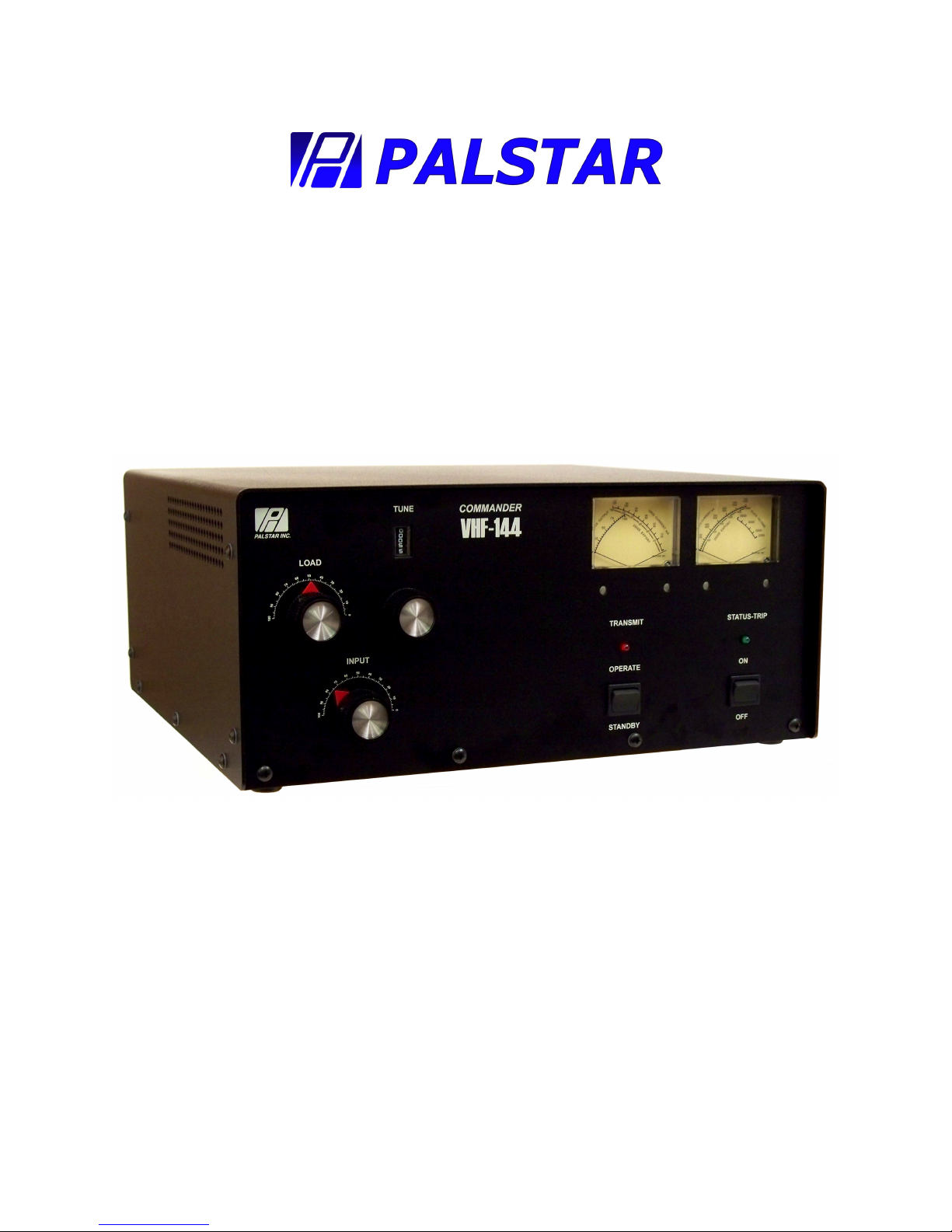
COMMANDER VHF-144
2 METER LINEAR AMPLIFIER
—————————————————————
Owner’s Manual
Customer Service and Sales Telephone: 800-773-7931
PALSTAR, INC.
Command Technologies Division
9676 N. Looney Road
Piqua, Ohio 45356
U.S.A.
Fax: 937-773-8003
E-mail: [email protected]
Page 2

Table of Contents
Introduction 3
Inside View 4
Specifications 5
Unpacking Instructions 6
Safety Warnings and Precautions 6
Front & Rear Layout 7
Installation Preparation 8
Operating Procedure 9
Operating Hints 10
Typical Operating Conditions Table 10
Warranty, Service, and Returns 11
HV Power Supply Schematic 12
AC Mains & Step-Start Schematic 13
Control & Metering Board Schematic 14
RF Deck Schematic 15
T/R Relay Board Schematic 16
Voltage Doubler Power Supply Schematic 17
PHOTO APPENDIX:
RF Deck 18
Dual Meters 19
Meter Board 20
Step-Start Board 21
Power Supply 22
2
Page 3

INTRODUCTION
The Commander VHF-144 is a grounded grid AB2 linear power amplifier that oper-
ates on the Amateur 2 meter band (144 to 148 MHz).
A single CPI/Eimac 3CPX800A7 pulse-rated external anode triode with forced air
cooling and modern stripline circuitry ensures efficient and conservative operation.
The 6:1 ratio vernier reduction drives on all tuning controls allow smooth and easy
tune up, while the front panel input tuning control allows a higher input circuit "Q" for
excellent linearity which presents a low input VSWR to the exciter across the entire
2 meter band.
An automatic delay circuit, for proper cathode conditioning before RF drive is applied,
which extends tube life. This is preformed by a microprocessor, which also controls a
step/start dual relay system for a safe and effective control AC input startup.
The Commander VHF-144 features a full compliment of control and metering functions for easy on-air operation. By using 2 cross-needle metering, it allows viewing of all
functions simultaneously.
This processor also features a gird-trip at 70ma of grid current. When activated by
overdriving the amplifier, the green LED will flash at a high rate.
Reset is provided by switching the operate/standby switch from operate to standby and
back again.
A dual primary power transformer allows 117VAC, 200VAC or 234VAC operation.
3
Page 4
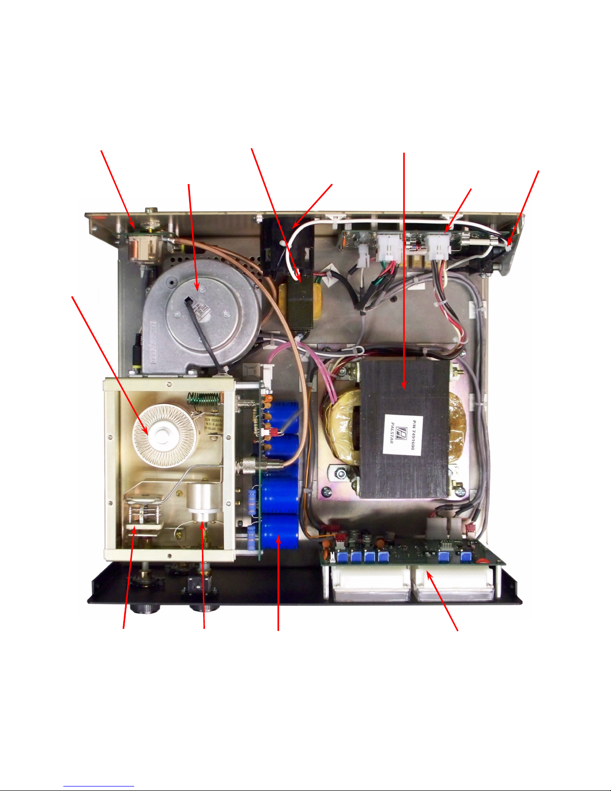
Commander VHF-144 Inside Layout
T/R Relay
Board
3CPX800A7
Triode Tube
Ball
Bearing
Cooling
Blower
Filament
Transformer
AC Input
Socket
High Voltage
Transformer
Step/Start
High Voltage
Interlock
Switch
PCB
Load Tuning
Capacitor
Input Tuning
Piston Capacitor
High Voltage
Board
4
Duel Meter
Control
Board w/ Mutliple
LED Backlighting
Page 5

Specifications
Commander VHF-144
2 Meter VHF Linear Power Amplifier
• Frequency Range: 144 to 148 MHz.
• Modes: USB, LSB, RTTY, FM, CW.
• Power Requirements: 200/234VAC 50/60 Hz.
• RF Drive Power: 10 to 15 Watts nominal; 30 Watts maximum, for full 1 KW (CW) output.
• Grid-trip Current: 70ma
• RF Output: 1 Kw pep (USB, LSB); 650 Watts cw FM, 450 Watts.
• Input Impedance: 50 Ohms unbalanced, front panel adjustable.
• Output Impedance: 50 Ohms nominal.
• Antenna Load (VSWR): 2:1 maximum.
• Harmonic Suppression: better than 60db down at rated output.
• Intermodulation Distortion: better than 35 dB down at rated output.
• Weight (with transformer): 43 lbs. (19.5 Kg).
• Cabinet Size: 14.5'' x 14.5'' x 6'' (36.8cm x 36.8 cm x 15.2 cm).
• Tube Compliment: one 3CPX800A7 ceramic pulse-rated metal triode.
• Cooling: pressurized chassis forced air, with a die cast bearing blower.
• Antenna Relay: DPDT; .1 dB insertion loss.
• Fuse: Type SFE; 234VAC and 200VAC operation: 15 Amp.
• Female AC plug on a 6’ 12ga 3-wire line cord included
5
Page 6

UNPACKING INSTRUCTIONS
Carefully remove your Commander VHF-144 from its shipping carton making sure there is
no damage evident from shipping. If there is any damage, notify the delivering shipper immediately, fully describing the damage.
Do not destroy the packing material, since it may be reusable later, should you require
factory service, or need to transport the Amplifier for any other reason.
CAUTIONS:
• DO NOT attempt any type of service or repair on this amplifier without first removing the
AC power and allowing AT LEAST 10 MINUTES FOR THE HIGH VOLTAGE CAPACI-
TORS TO BLEED OFF !
• DO NOT operate this amplifier with the top or bottom covers removed. DO NOT operate
this amplifier with the internal RF tube compartment covers removed.
• CONTACT WITH VOLTAGES IN THE CABINET CAN BE FATAL ! CLOSE QUAR-
TER EXPOSURE TO UNSHIELDED RF AT THESE POWER LEVELS AND FREQUENCY IS HAZARDOUS TO YOUR HEALTH !
• Never attempt operation without first connecting an appropriate antenna (2:1 VSWR Max)
or a 50 ohm dummy load with sufficient rating or SERIOUS DAMAGE TO THE AMPLI-
FIER MAY RESULT.
• Never operate the amplifier with more drive than required to produce the rated output for
the operating mode used (Max 25-30 Watt).
• Do not place the Commander VHF-144 in repeater operation. This amplifier is not designed
for unattended service. Extensive modification would be required for this type of service.
• Never operate any amplifier using an extension cord.
IF ANY SITUATION YOU ARE NOT SURE ABOUT OCCURS,
PLEASE CONTACT MANUFACTURER FOR ASSISTANCE.
!! WARNING !!
CONTACT WITH VOLTAGES IN THIS AMPLIFIER CAN BE
!!! FATAL!!!
6
Page 7
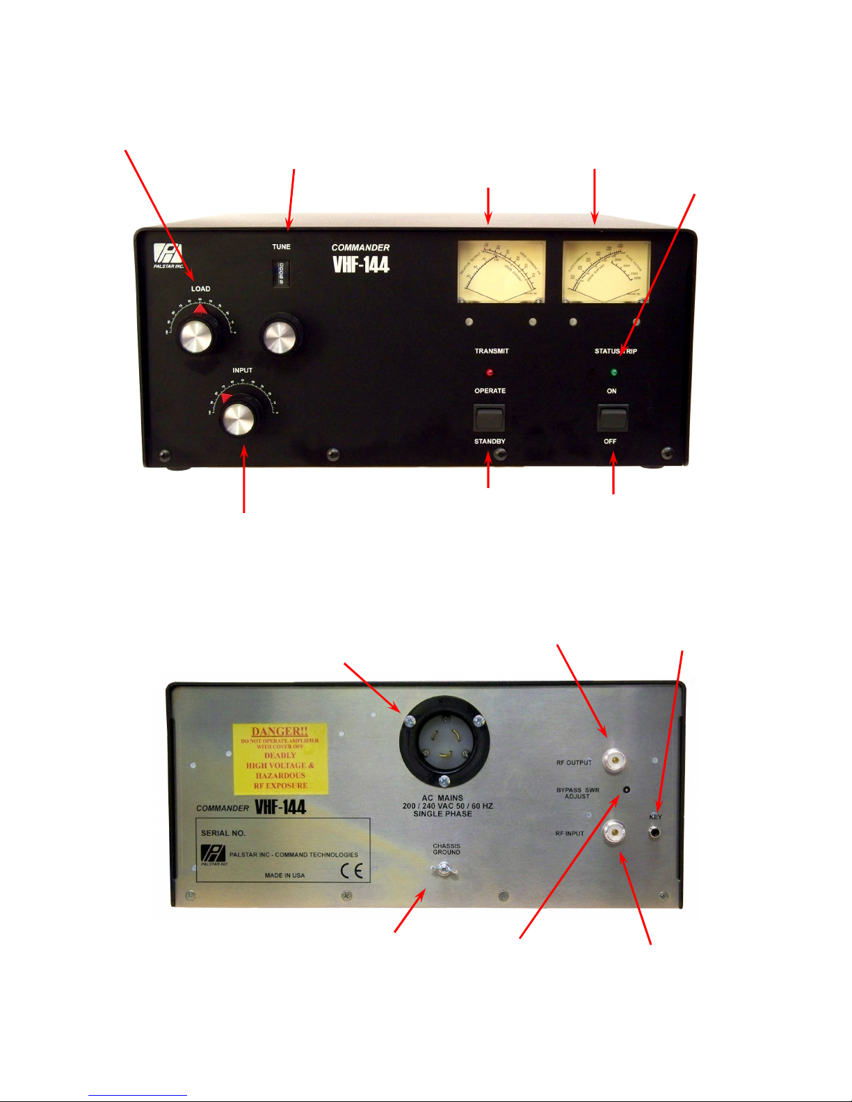
Front Panel Layout
LOAD
Control
TUNE Control
Multi-turn Piston Capacitor
Preset at Factory
INPUT
Control
Multimeter:
Relative
Output/Grid
Current
STANDBY/
OPERATE
Switch
Multimeter:
Plate Current/
Plate Voltage
ON/OFF
Switch
Power Ready
Light
Rear Panel Layout
AC Power
Socket
Ground Lug
Bypass SWR
RF Out
Adjust
(PTT) Key
RF In
7
Page 8
INSTALLATION PREPARATION
The Commander VHF-144 is factory wired for operation from an 234VAC line. Operation at
the full rated output should not be attempted unless the AC line is capable of supplying at least
15 amps of peak current. It is strongly recommended that you operate this amplifier from a
234VAC line.
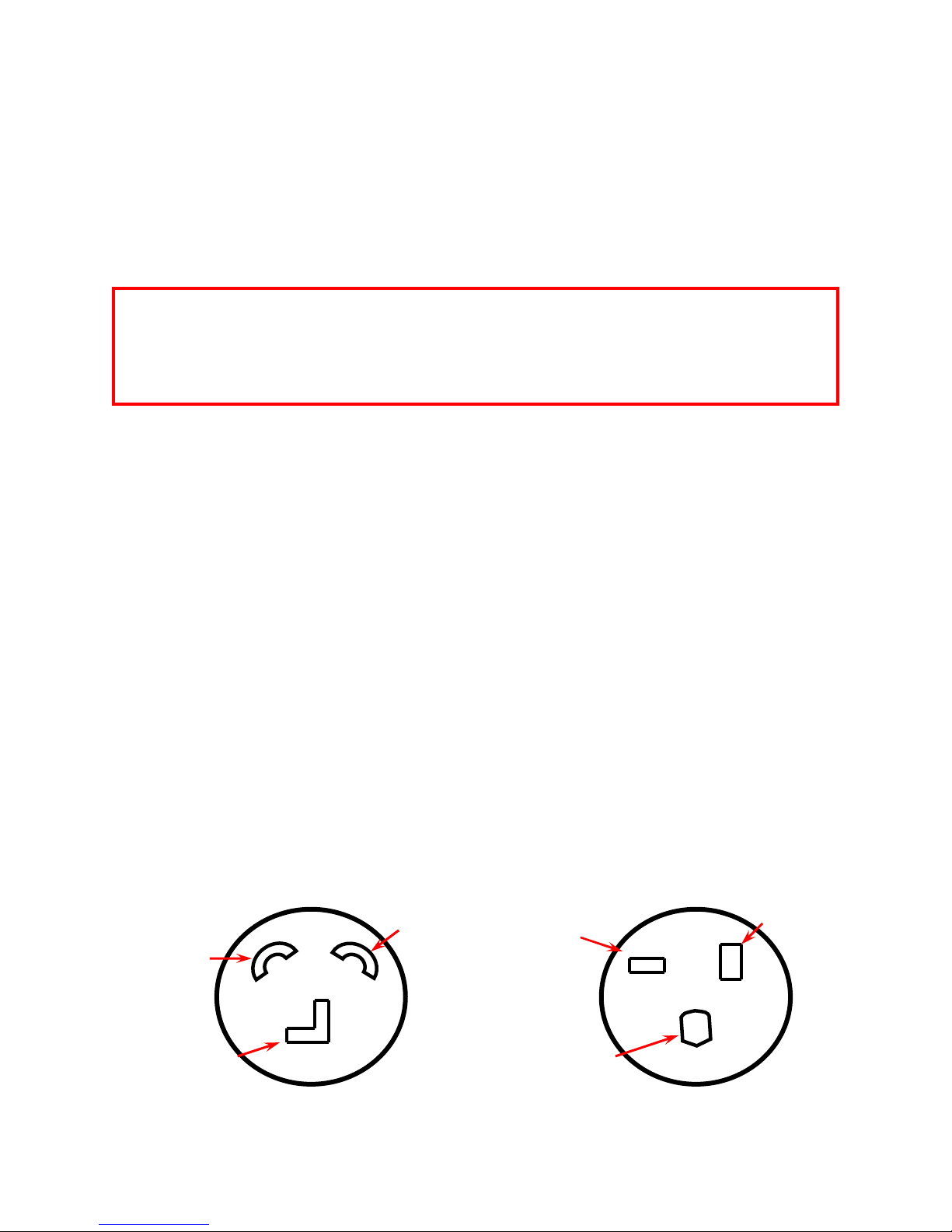
Install an appropriate plug on the end of the power cord to mate with your wall receptacle.
!!CAUTION!!
BE SURE YOU HAVE REMOVED THE LINE CORD PLUG FROM YOUR WALL
SOCKET BEFORE REMOVING THE JUMPER COVER. IF YOU FAIL TO UNPLUG
YOUR AMPLIFIER, YOU WILL EXPOSE YOURSELF TO LETHAL VOLTAGES.
If you change the operating voltage as described above, be sure to install the proper fuse.
The fuse is a type SFE, 20 Amp for 234 VAC & 200 VAC operation.
All Commander VHF-144 amplifiers manufactured for export are wired for 200 or 234VAC,
50 or 60 Hz, depending on the final destination. No plug is supplied with the AC line cord.
Location of your Commander VHF-144 requires that no equipment be placed directly
against the left side vent, as air expelled from the tube exhaust can become quite hot. Allow at
least 3 inches clearance on the side of the unit and between other equipment.
To switch from transmit to receive the Commander VHF-144 requires a contact closure or
keying circuit capable of sinking 15ma of positive voltage (12 VDC open circuit) to ground.
This connection is made to the RCA jack on the rear panel marked KEY. Read the manual that
came with your transceiver to determine the proper external connections. On some transceivers,
this is not provided, and an alternate circuit will be required. Always use shielded cable for
these connections.
Connect a good quality thru-line analog Wattmeter between the amplifier output jack and the
antenna or dummy load using RG8 or better coax.
Connect the exciter (transceiver) RF output to the amplifier input using 50 ohm coax.
Connect a ground lead, as short as possible, from earth ground to the Commander VHF144’s rear panel ground terminal.
Amplifier Wall Outlet
Black
Black
(230 VAC)
Green
(Ground)
White
(Natural)
White
Green
AC SOCKET CONNECTIONS
8
Page 9

OPERATING PROCEDURE
After reading this manual and completing the Installation/Preparation Instructions, position
the Commander VHF-144 front panel controls as follows:
• ON/OFF — OFF
• OPERATE/SSTANDBY — STANDBY
• INPUT — CENTER ON SCALE (50-55 on Scale)
• LOAD — MINIMUM (COUNTER-CLOCKWISE) (100 on scale is minimum capaci-
tance)
• TUNE — LEAVE AT FACTORY SETTING (NOTE: the TUNE control is a multi-turn
piston capacitor and was factory preset for operation at 144.200 MHz.
Factory Setting Tune is 55.
After presetting these controls, switch the ON/OFF switch to the ON position. The meter
lamps will illuminate, the blower will be running and plate voltage will be approximately 2800
VDC.
The 3CPX800A7 used in this amplifier requires a warm up period before RF drive may be
applied, to prevent damage to the tube. A 2 minute warm up is provided by a microprocessor
circuit. During warm-up the green LED will flash at 1sec rate. At the end of the warm-up period, the green POWER LED on the front panel illuminates on fully and the unit is ready for
operation.
Switch the OPERATE/STANDBY switch to the OPERATE position and key the exciter with
ZERO RF drive applied. The Red Transmit light should illuminate, the tube will be biased
“on”, and plate idling current should be approximately 60 ma. as displayed on the Ip meter
scale.
Apply a very low RF drive (less that 5 watts) and adjust the INPUT control for a peak in the
plate current (Ip) on the meter. Next adjust the TUNE control for maximum output as indicated
on an external Wattmeter. DO NOT adjust the LOAD control at this time. COMPLETE
THESE ADJUSTMENTS AS QUICKLY AS POSSIBLE TO AVOID STRESSING THE
TUBE.
Key the exciter in FM Mode (For Tune Procedure), and while increasing the RF drive, adjust
the LOAD control clockwise in order to keep the grid current below 40ma. and to obtain a peak
in output power on an external wattmeter (see chart: Typical Operating Conditions chart on the
next page).
Re-peak the TUNE control for maximum output at 600ma of plate current.
The Commander VHF-144 is ready for SSB or CW on the air operation. Normal SSB operation is indicated by plate current readings on voice peaks of approximately 1/3 to 1/2 of the CW
key down value.
For FM or other high duty cycle modes, limit drive to 10-15 watts maximum.
9
Page 10
OPERATING HINTS
The Commander VHF-144 TUNE control is a high "Q" piston-type tuning capacitor with a 6:1
ratio vernier reduction drive. This control requires about 15 revolutions to tune the unit from
144 to 148 MHz.
Unless you have specified another band segment, the unit is factory tuned at 144.200, the national SSB calling frequency. If you use the Commander VHF-144 mainly for CW and SSB,
and after having tuned the unit to your antenna, you will be able to QSY up or down the CW/
SSB band segment without making any tuning adjustments. Unless someone changes these adjustments, it will not be necessary to retune the amplifier each time you operate it. Just turn the
unit on, wait for the green light and begin transmitting.
If you decide later to operate in the FM portion of the band, it is best done by tracking up the
band about 500 KHz at a time. To do this, key the exciter with low drive (5 watts or less), retune INPUT for a peak in plate current (Ip), and readjust TUNE control for maximum output,
repeating this procedure as you move up the band. This is also useful if you happen to forget
where you left it tuned.
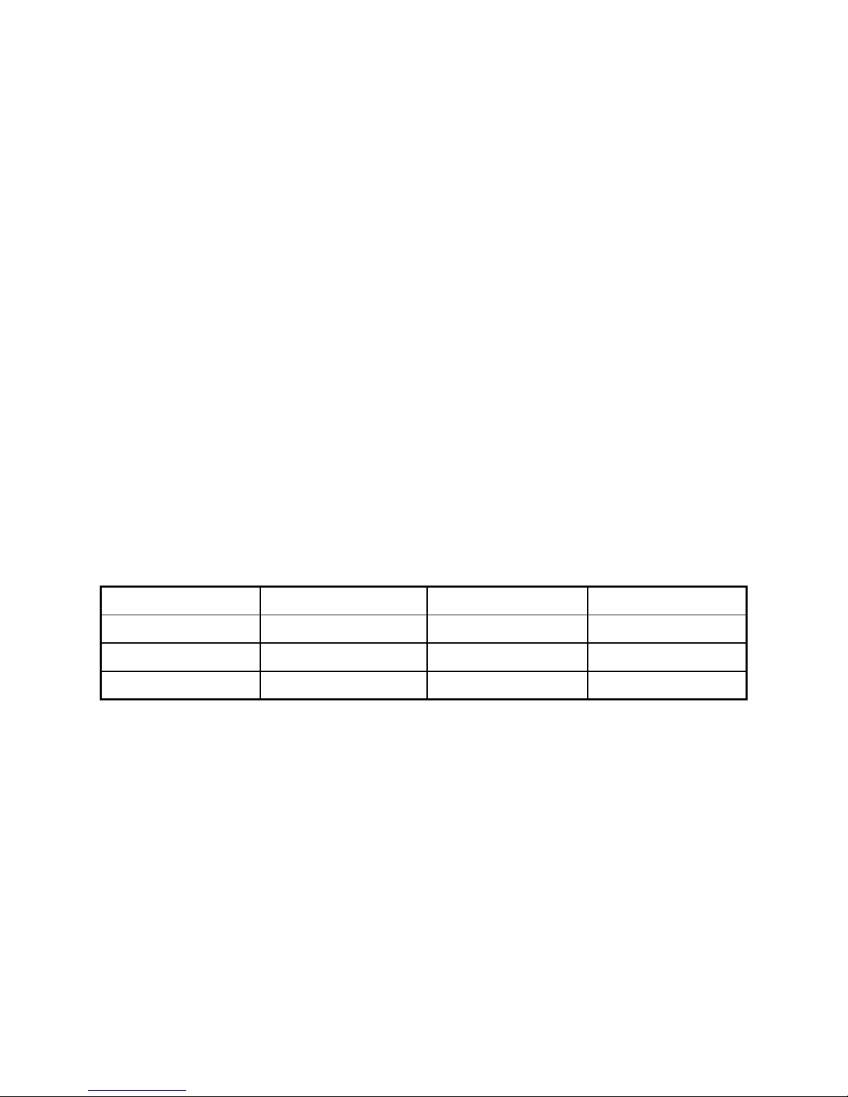
TYPICAL OPERATING CONDITIONS
DRIVE GRID CURENT PLATE CURENT POWER OUTPUT
12.5 Watts 15 ma 400 ma 450 Watts
18.5 Watts 25 ma 500 ma 650 Watts
30 Watts 35 ma 600 ma 1000 Watts
10
Page 11

Limited Warranty
Palstar Inc. warrants the Commander VHF-144 to be free from defects in material and workmanship under normal use and service for a period of one (1) year from the date of delivery
to the first buyer (the “Warranty Period”). Palstar Inc.’s obligation under this warranty is limited to repair or replacement of the product at it’s option at the Palstar factory in Piqua, OH.
This warranty is effective only when the product is returned to the factory with all transportation charges prepaid and examination of the product discloses, in Palstar’s judgment, to have
been defective during the Warranty Period.
The Warranty Period shall not extend beyond its original term with respect to interim inwarranty repairs by Palstar. This Warranty Period shall not apply to any product which has been
repaired or altered by anyone other than Palstar without prior written authorization. Warranty
does not extend to any products which have been subject to damage from improper installation,
application or maintenance in accordance with the operating specifications. Palstar neither assumes nor authorizes any person to assume for it any obligation or liability other than herein
stated.
Shipping Your Amplifier Back to the Factory
Due to the necessity of shipping the amplifier with the HV transformer removed, please
contact the factory for instructions before sending an amplifier back to us. There are circumstances in which it may not be necessary to return the HV transformer, thereby saving you shipping charges. When you call, Palstar will inform if transformer return is necessary. If transformer return is necessary, remove it from the amplifier cabinet and ship it separately, preferably in its original crate.
Repair Policy
When sending in a product for service, see the section above. If not using the original packing materials, please “double” box it carefully and ship it insured for your protection. Please
include a note clearly describing the problem, how you wish the item returned and how you
wish to pay for the service. Package your unit properly. Palstar, Inc. is not responsible for merchandise damaged in shipment. Our service rate is $30 per hour (1/2 hr. minimum).
Return Policy
All returns must receive prior authorization from Palstar. Returned items must be received in
original—AS SHIPPED—condition including the original box, manuals, accessories, and copy
of sales receipt. Returns must be within 14 days of purchase. Returned items are subject to a
20% restocking fee. Shipping is not refundable.
11
Page 12
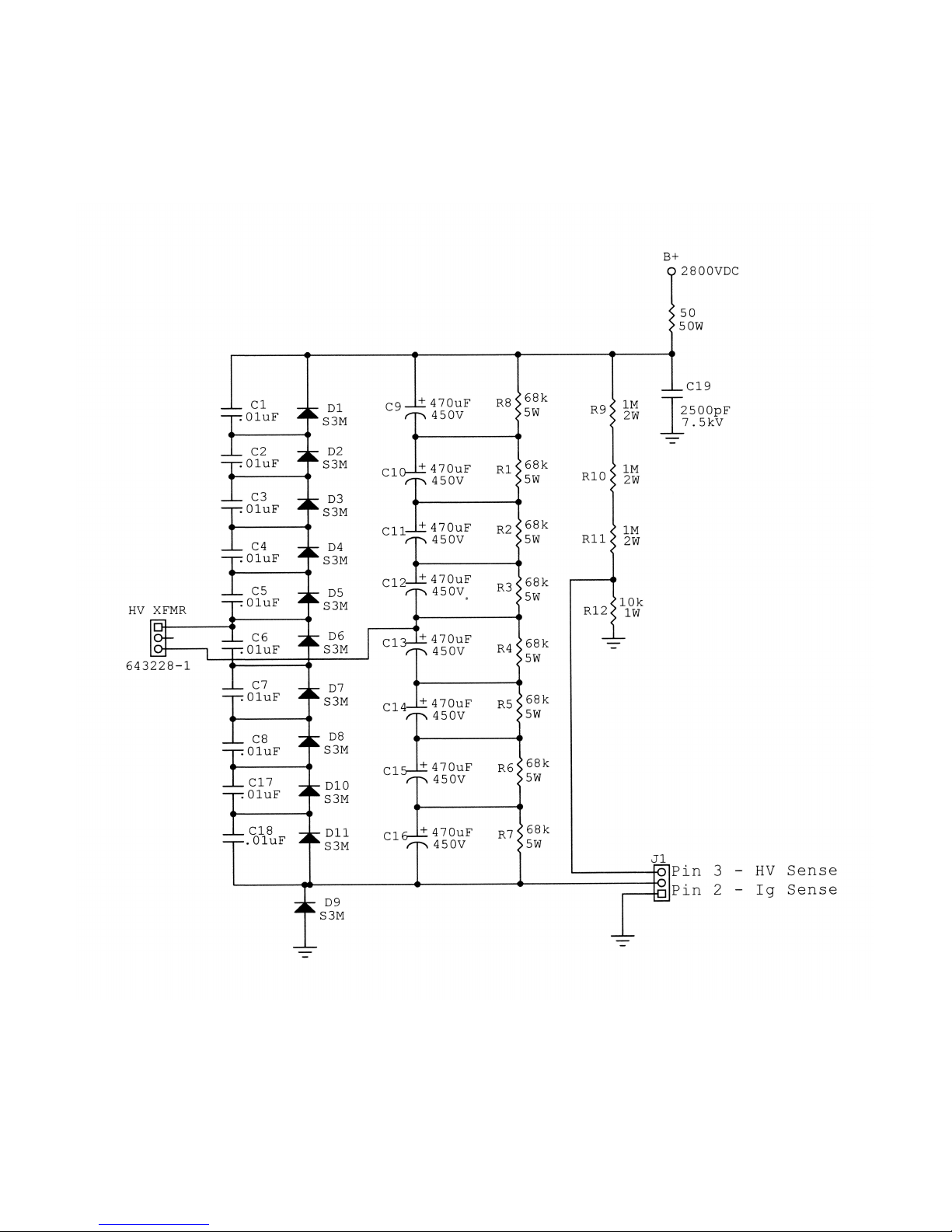
Commander VHF-144 HV Power Supply
12
Page 13
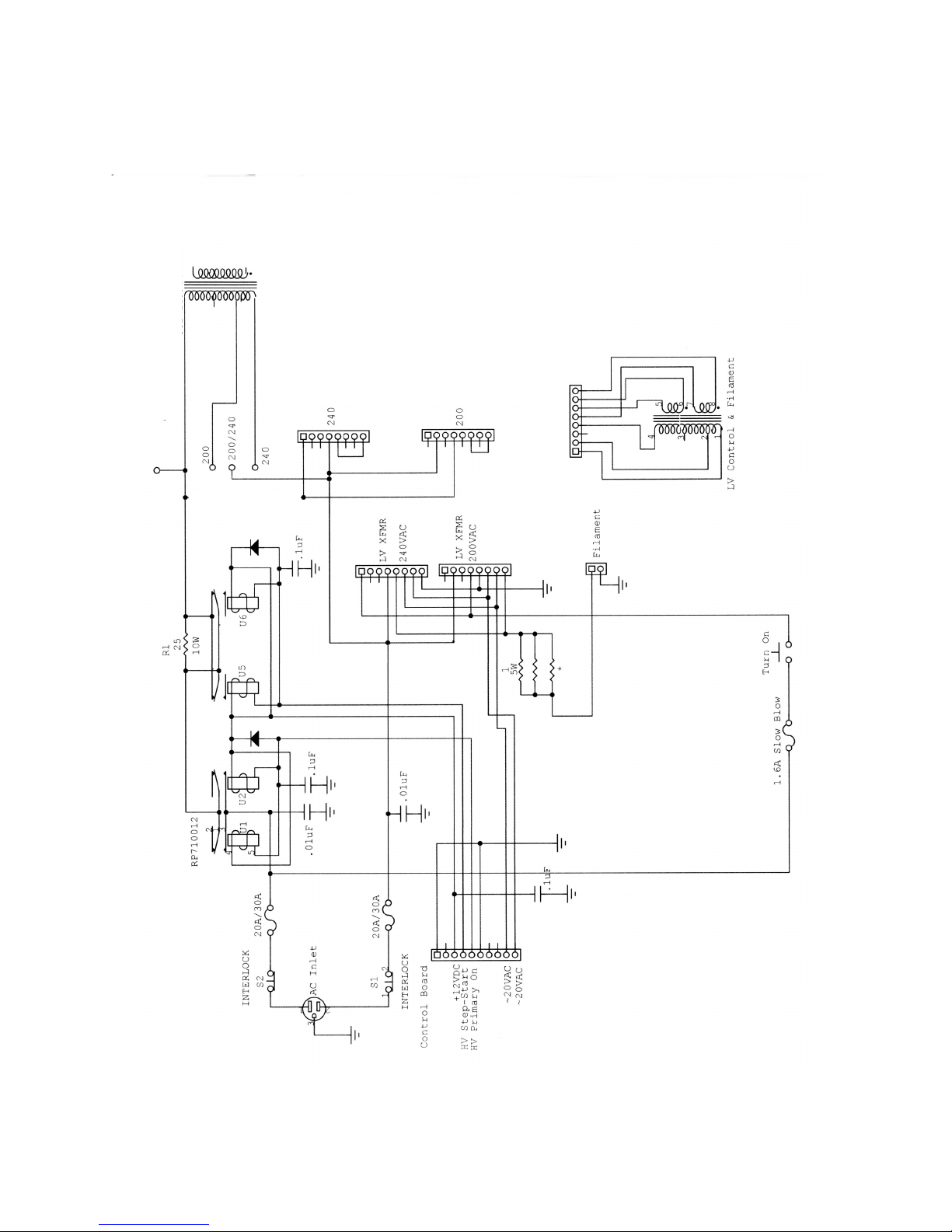
~13.5VAC
AC Mains and Step-Start Board (VHF-144)
13
Page 14
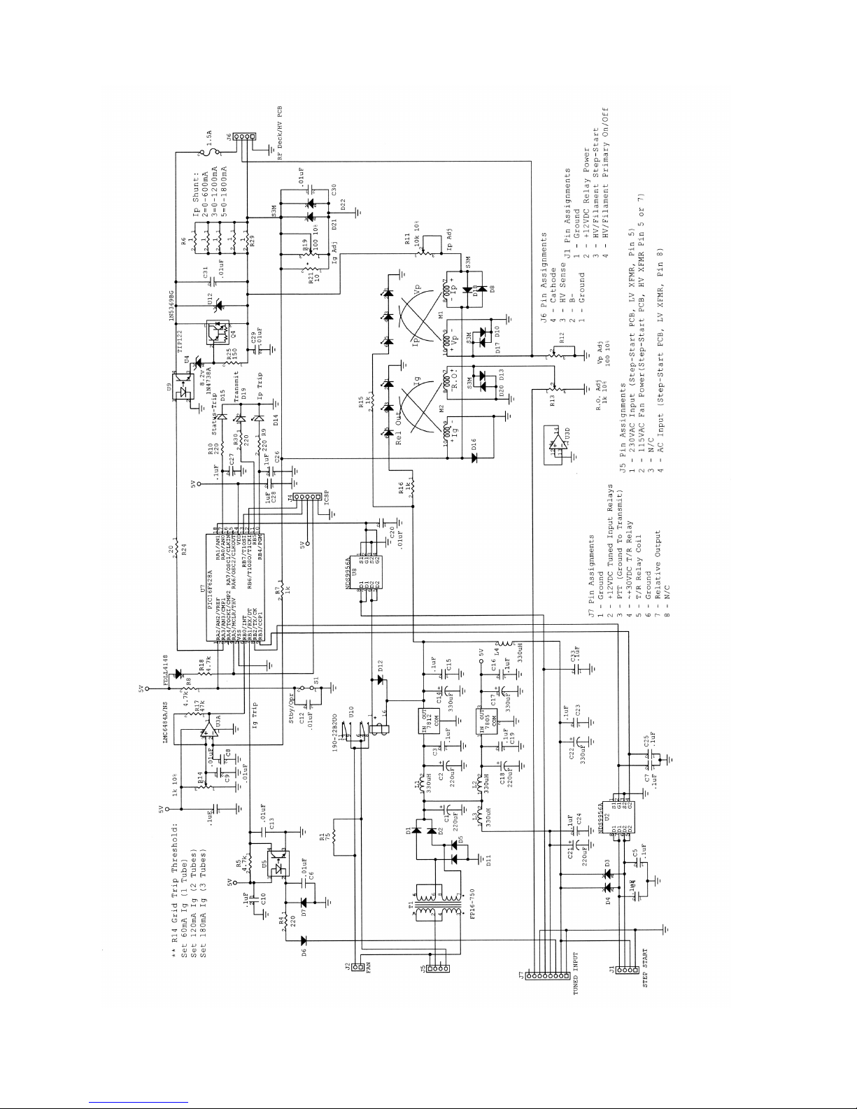
Control and Metering Board VHF-144
14
Page 15
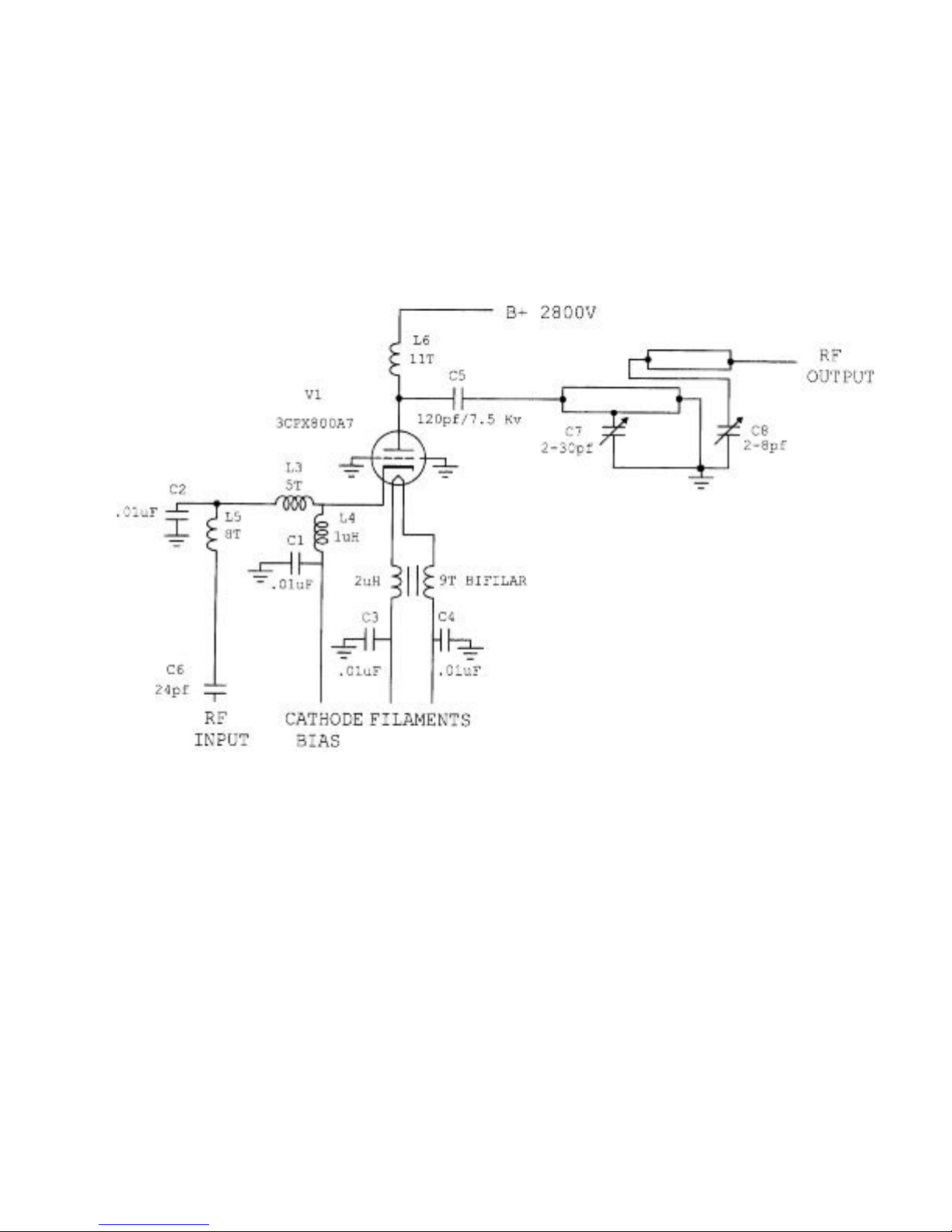
RF Deck VHF-144
15
Page 16
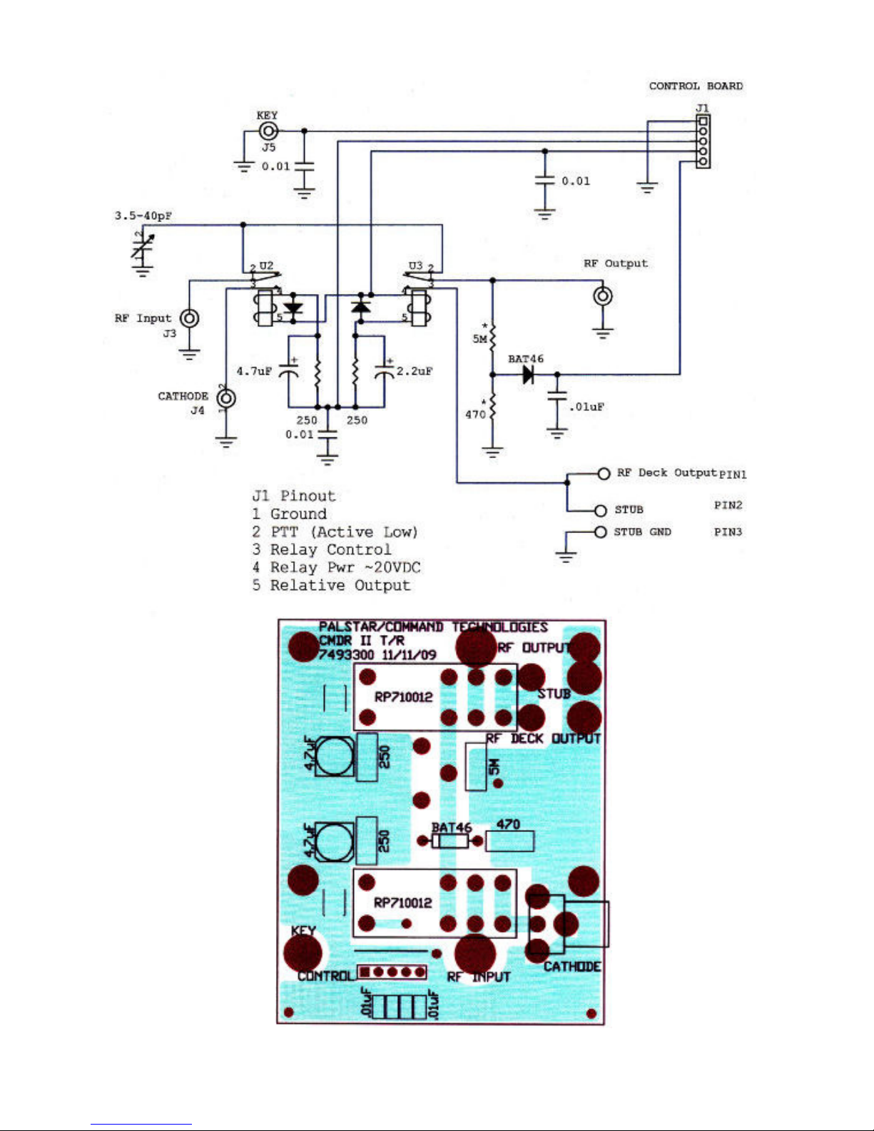
Commander VHF-144 T/R Relay Board
16
Page 17
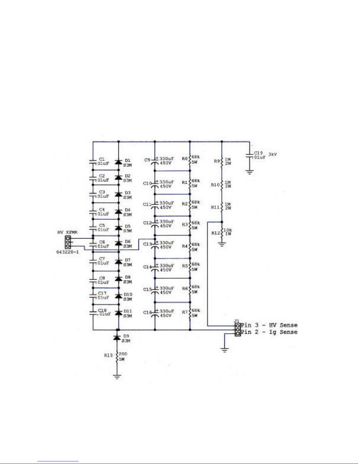
Commander VHF-144 Voltage Doubler Power Supply Board
17
Page 18
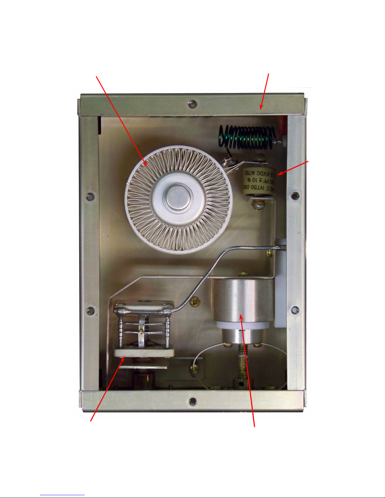
RF Deck
3CPX800A7
Triode Tube
RF Plate Choke
Plate
Capacitor
120pf/7.7kv
Load Tuning
Capacitor
Input Tuning
Piston Capacitor
18
Page 19
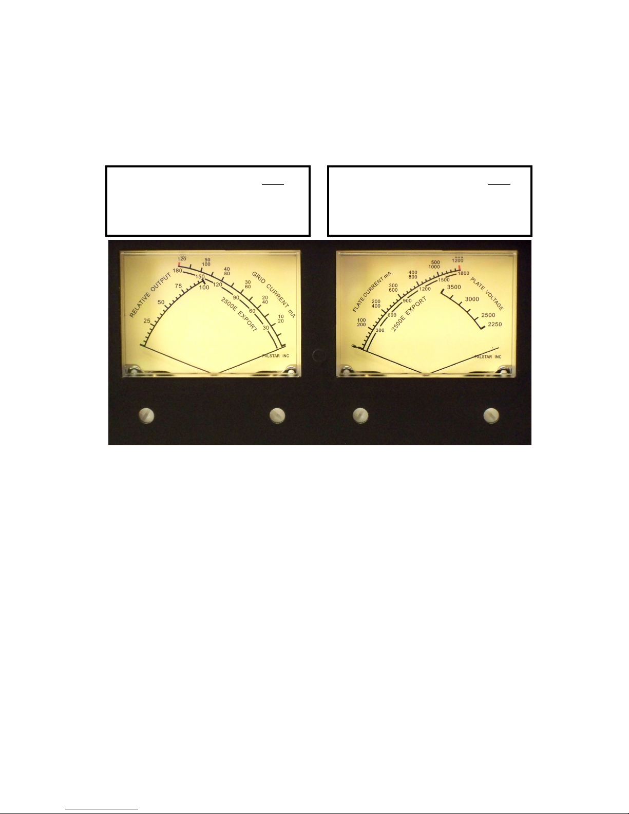
Dual Meters
Grid Current: Scale
0-60ma Single Tube Top
0-120ma Two Tubes Mid
0-180ma Three Tubes Bottom
Grid Current: Scale
0-600ma Single Tube Top
0-1200ma Two Tubes Mid
0-1800ma Three Tubes Bottom
19
Page 20
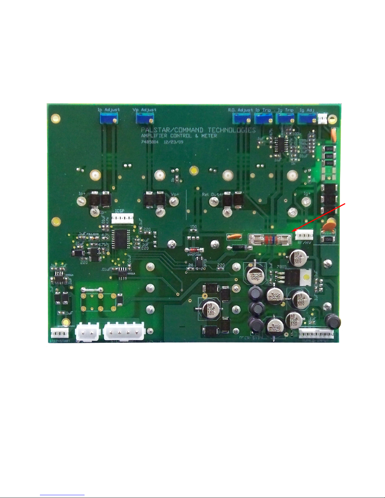
Meter Board
Cathode
Fuse
20
Page 21
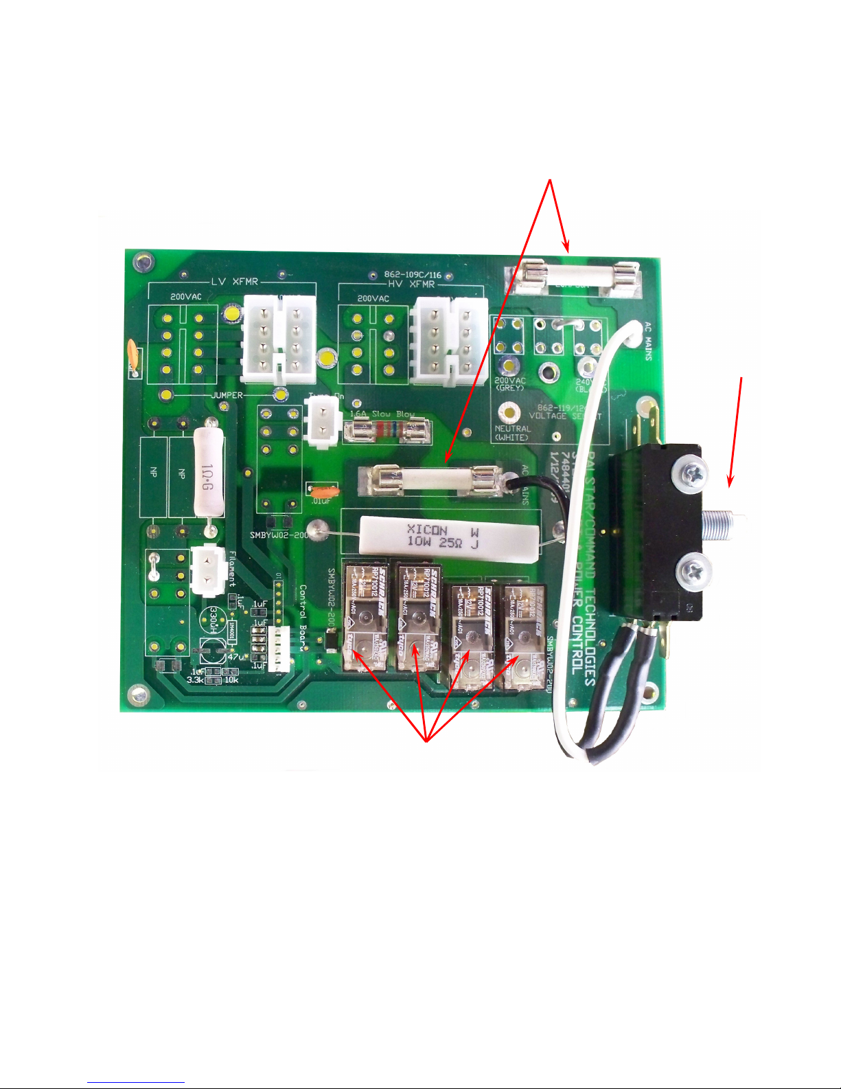
Step-Start Board
AC Main Fuse
(20A) x 2
AC
Interlock
Step/Start Relays x 4
21
Page 22
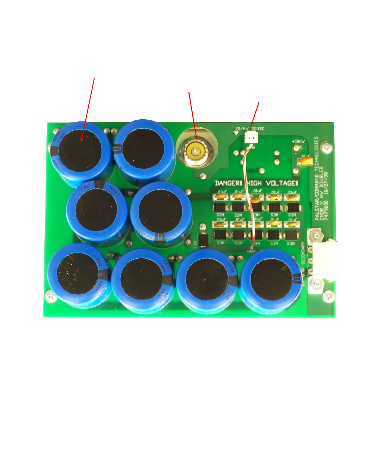
Power Supply
470uF Capacitor
450 vdc x 8
RF Output
HV Sense
22
Page 23

23
Page 24

Palstar Incorporated
9676 N. Looney Rd.,
Piqua, OH 45356 USA
Customer Service and Sales Telephone:
1-800-773-7931
Fax:
1-937-773-8003
Email:
Version 1.0 2010.03.29
24
 Loading...