

Page 1

Palstar products are designed by
Hams for Hams carrying on the
Palstar tradition for high-quality
products designed and
manufactured in Ohio, USA.
AT4K 2500 Watt
Antenna Tuner
2500 W single tone, low loss, wide Z range
160m to 15m
Custom variable capacitors and inductor
Dual movement cross needle meter
6.5” x 15” x 16”
PALSTAR
AT4K 2500 Watt Antenna Tuner
Technical Manual
9676 N. Looney Rd,
Piqua, OH 45356 USA
(937) 773-6255
(800) 773-7931
(937) 773-8003 (Fax)
www.palstar.com
PALSTAR
Designed and Manufactured in the USA
Copyright 2018 Palstar, Inc.
Page 2
AT4K SPECIFICATIONS
METERING: Dual movement cross-needle power
and frequency compensated coupler
INPUT & ANTENNA TUNING: 2 x Variable capacitors 480 pF, 6 kV
Peak 6:1 Vernier Drives for capacitors
INDUCTANCE: 28 μH roller inductor, 10 ga. wire wound on
steatite ceramic core, plated bar & wheel
ANTENNA SELECTOR SWITCH: 6 position:
Coax 1 - tuned and tuner bypass
Coax 2 - tuned and tuner bypass
Bypass coax connector;
Balanced antenna
Switch wafers are 7 kV/10A rated
POWER RANGE SWITCH: 2 position 300 W / 3000 W
REAR PANEL CONNECTORS:
SO-239: RF Input, Coax 1 & 2, Bypass
END FED WIRE: High Voltage Nylon66™
terminal/ground posts for Balanced Line
12 VDC INPUT: 14mm connector, 2.1mm ID,
5.5mm OD, center positive, 200 ma
FREQUENCY COVERAGE: 1.8 - 29.5 MHz
POWER MAXIMUM: 2500 W single tone continuous, 3000 W PEP
IMPEDANCE RANGE: 8 Ω to 2000 Ω, 160m to 10m
(assuming resistive load)
Reduce power for lower Z-range
BALANCED OUPUT: 1:1 current type balun at input-Ferrite
DIMINSIONS: 6.5” H x 15“ W x 16” D (incl. terminals)
WEIGHT: 22 LBS, 10 Kg
CHASSIS & COVER: 11 ga., .090 gold Iridite Treated Aluminium
AT4K GENERAL DESCRIPTION
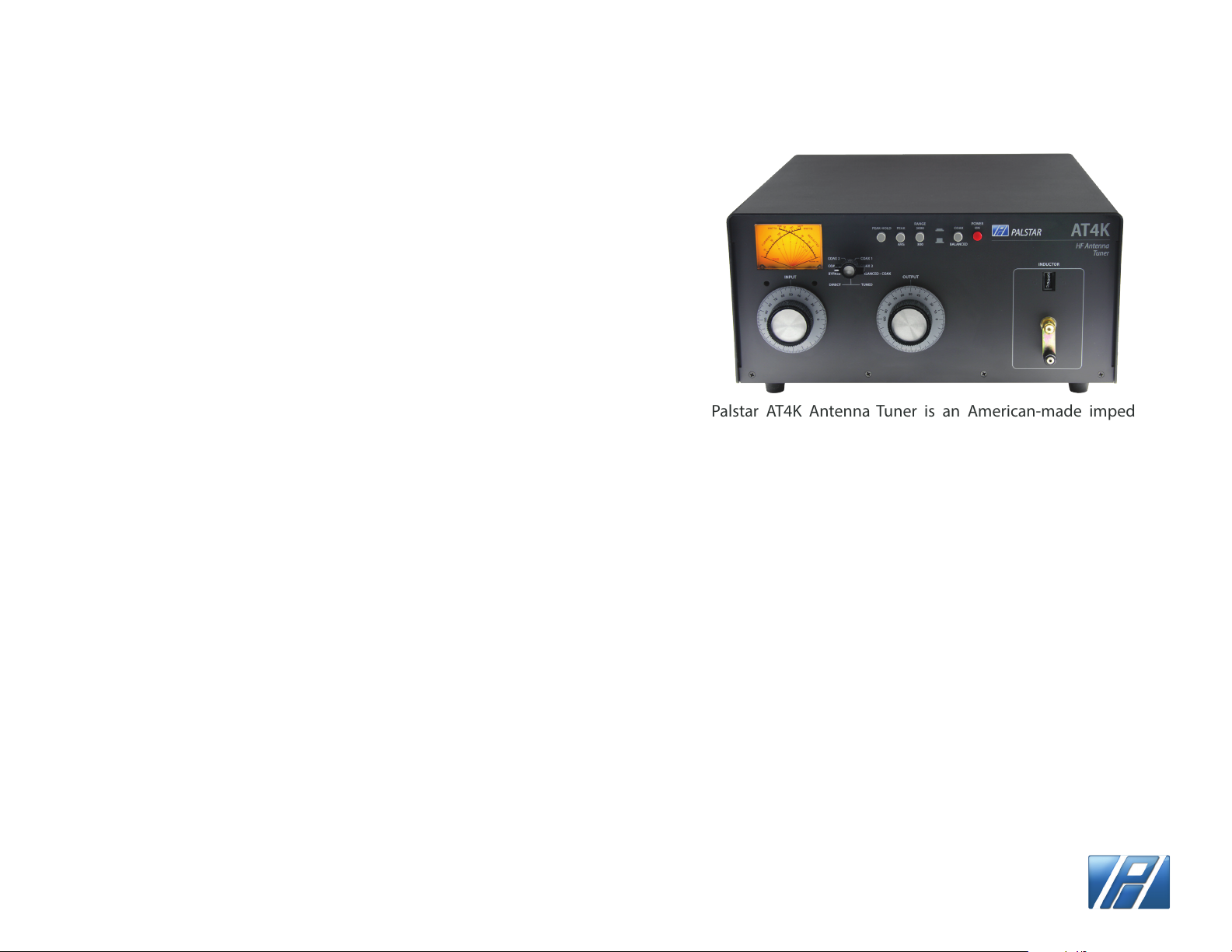
The Palstar AT4K Antenna Tuner is an American-made impedance
matching network that can provide unbalanced and balanced ouput
with a power rating of 2500 watts (single tone continuous) and 3000
watts PEP at certain Z ranges.
The AT4K T-matching network utilizes a 1:1 unbalanced to balanced
transformer in the input of the network. When the network is properly
tuned, a 50 Ohm impedance will be presented to both the input and
output of the balun for maximum eciency.
The AT4K optimizes the performance of your antenna and transmitter
by providing adjustable impedance matching using a T-type circuit
conguration. The AT4K also measures the power and Voltage
Standing Wave Ratio (VSWR), which allows you to tune the SWR to the
lowest ratio for the selected transmission frequency.
Integrated into the AT4K is a frequency-compensated lighted-dial
dual-movement SWR meter. The meter features the ability to read True
Active Peak and Peak Hold.
Designed to handle both Balanced line feeds and Coax feeds the AT4K
features a front panel mounted switch to select between feeds.
Tuning is achieved with the front panel mounted
controls. The Vernier capacitor dials allow for tuning with
precision and accuracy, while the inductor crank handle
facilitates coarse adjustments.
Page 2 PALSTAR
Page 3
INSTALLATION
UNPACKING
Carefully remove the AT4K from the shipping carton and
inspect it for signs of damage. If any damage is apparent,
notify the transportation carrier or dealer immediately.
KEEP THE PACKING CARTON for moving, storing, or
reshipping the tuner to us for repair if required.
LOCATION
Select a location for the AT4K that allows the connectors
to be free from any possible contact with people, pets,
or objects during operation and with unrestricted air
ow for cooling.
REAR PANEL
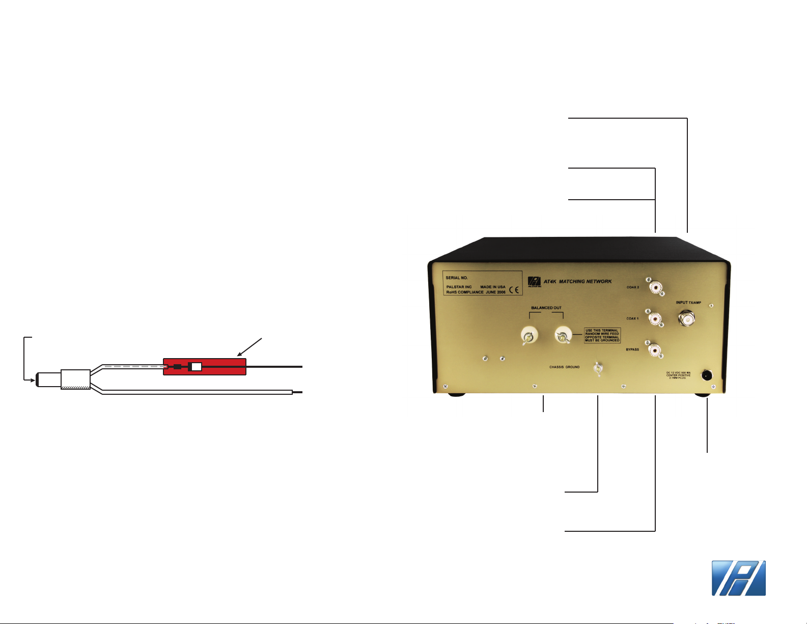
RF INPUT coaxial
connector for input from
transmitter or amplier
COAX 1 coaxial connector
for output to Antenna 1
COAX 2 coaxial connector
for output to Antenna 2
2.1 mm
FEMALE plug
Grey
TRACE ID
Protection
Reverse diode
Red Heat Shrink
cover
+
To 12-13.8v
Power Supply
-
AT4K DC POWER CORD
INSTALLATION PROCEDURE
Connect a coax cable from your transmitter to the RF
INPUT connector on the rear panel. Keep the cable as
short as possible. If you use a linear amplier, connect
your transmitter to the linear amplier input and the
linear amplier output to the AT4K.
DO NOT USE MORE THAN 3500 WATTS (single tone
continuous) through the tuner.
Page 3
BALANCED OUTPUT
Two nylon High Voltage post
connectors for output to RF
balanced twin-lead antennas.
Relay switch from front panel.
GROUND post/wing nut
ground connector
BYPASS coaxial
connector for output to
dummy load or resonant
antenna. Bypasses tuner,
but meter circuits are on
if 12VDC adapter is
connected to rear panel
12 VDC INPUT
(2.1 mm plug,
center pin +)
12 VDC adapter
500 mA to power
the metering ,lamp,
relay, and fan.
PALSTAR
Page 4
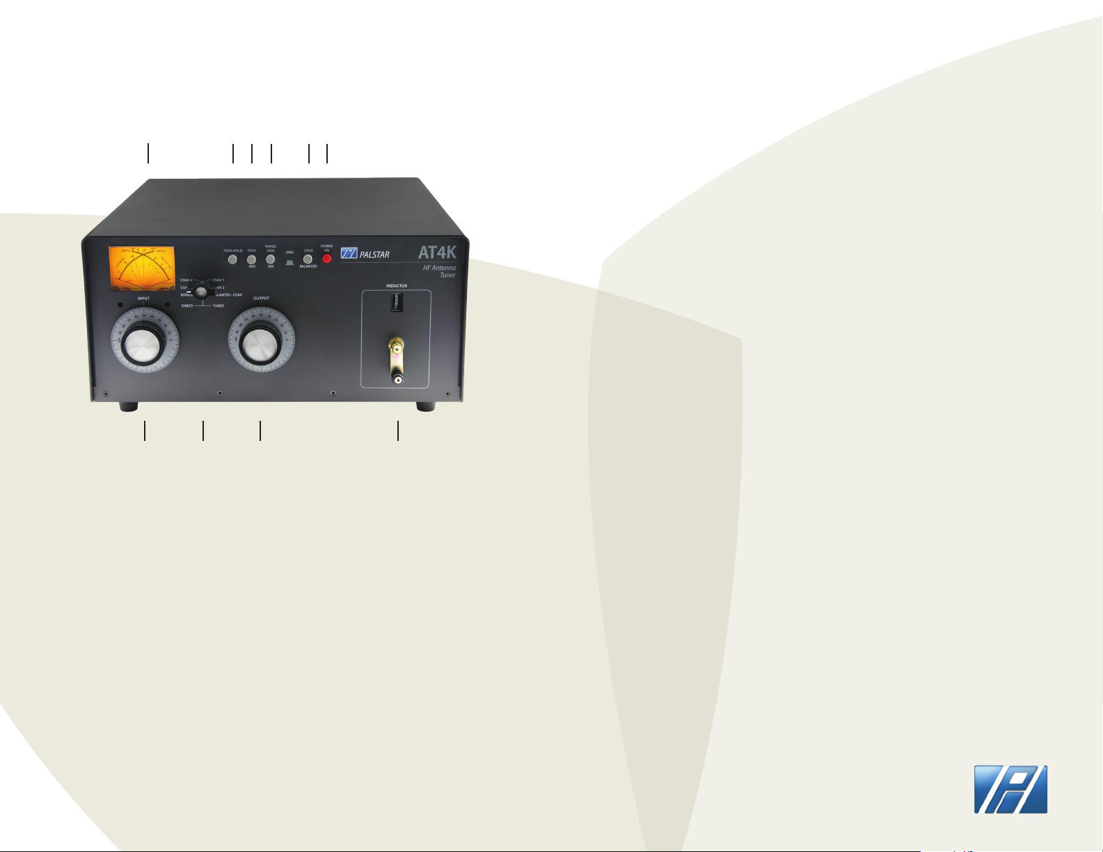
1 2 3 4 5
FRONT PANEL DESCRIPTION
6
7. INPUT Continuosly adjustable input capacitor. Min.
capacitance = 0. Max. = 100.
8. DIRECT-TUNED MODE SWITCH Six-position rotary switch selects an
output coaxial connector.
a. DIRECT BYPASS selects BYPASS COAX CONNECTOR bypassing the
impedance matching circuit, but providing SWR, FORWARD, and
REFLECTED power meter readings.
b. DIRECT COAX 1 selects COAX 1 CONNECTOR bypassing the tuner
matching circuit, but providing SWR, FORWARD, and REFLECTED meter
readings.
7 8 9 10
1. POWER/SWR METER Dual needle meter displays FORWARD and
REFLECTED power in watts. SWR is measured where the two needles
intersect on the red scale. SWR is printed on meter face.
2. PEAK HOLD Select to read PEAK HOLD on the SWR meter for 2 seconds.
PEAK switch must be in PEAK position.
3. PEAK Selects between PEAK (IN) and AVERAGE (OUT) metering display.
4. RANGE The power range is 300 watts on low and 3000 watts on high
(push button in for high).
5. BALANCED/COAX Selects either coax feed or balanced feed. A LED
shows when balanced mode is selected.
6. POWER ON The IN position provides power for the PEAK and PEAK
HOLD metering circuit, relay and meter illumination.
Page 4
c. DIRECT COAX 2 selects COAX 2 CONNECTOR bypassing the tuner
matching circuit, but providing SWR, FORWARD, and REFLECTED meter
readings.
d. TUNED COAX 1 selects COAX 1 CONNECTOR through the impedance
matching T circuit.
e. TUNED COAX 2 selects COAX 2 CONNECTOR through the impedance
matching T circuit.
f. TUNED COAX BAL selects the END FED WIRE connector through the
impedence matching circuit. For balanced antennas, the balanced coax
switch (5) must be IN.
9. OUTPUT Continuously adjustable output capacitor. Min.=0; Max.=100.
10. INDUCTOR 28 H continuously variable ceramic roller inductor driven
by a crank handle. Coupled to the crank handle is a gear-driven
precision mechanical counter; Max. = 0; Min. = 229.
μ
PALSTAR
Page 5
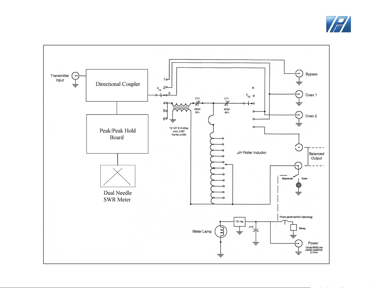
AT4K SCHEMATIC
PALSTAR
28
Page 5
COPYRIGHT PALSTAR 2018©
Page 6
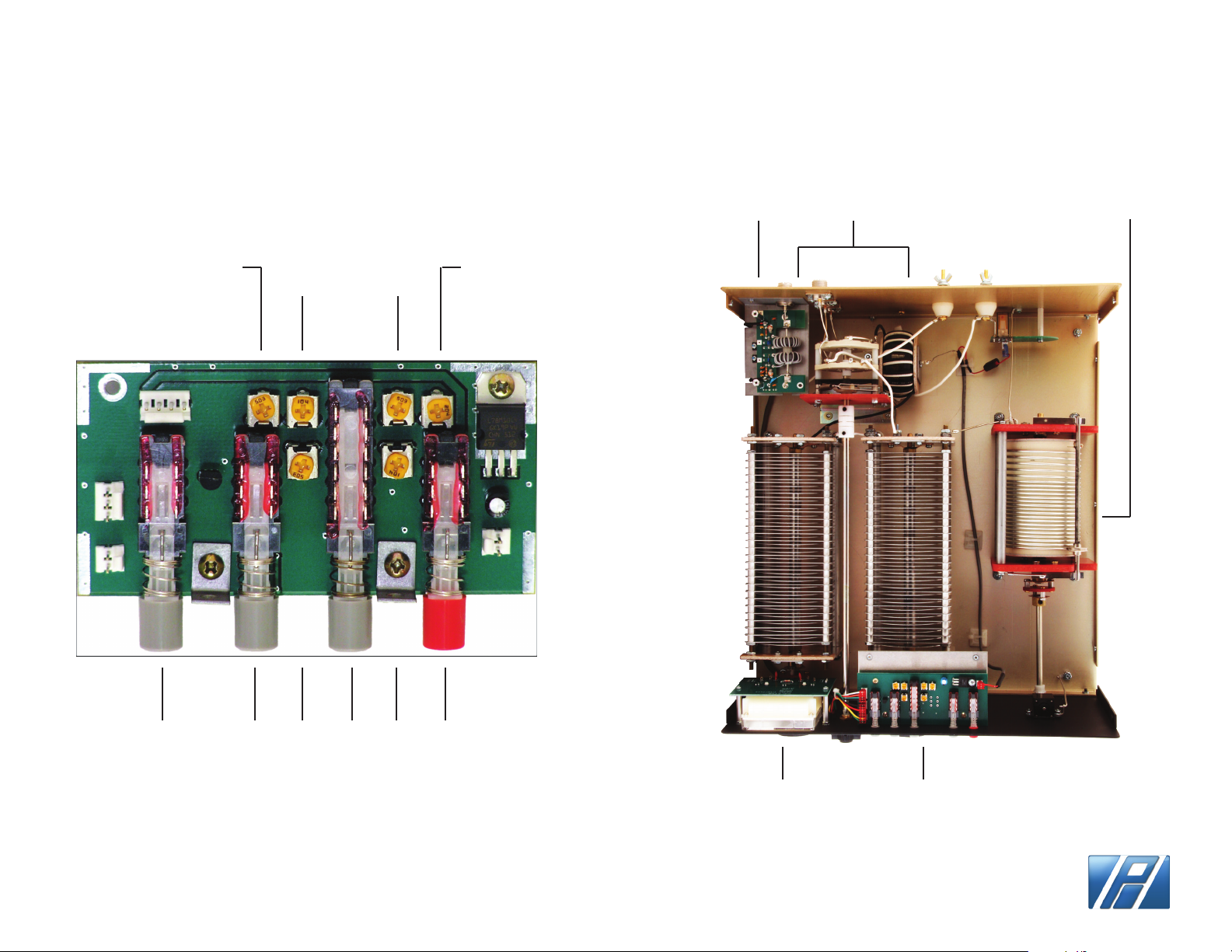
METER BOARD ADJUSTMENTS
INSIDE VIEW
Reverse
Low
Reverse
High
Forward
Low
Forward
High
COUPLER
VARIABLE
CAPACITORS
ROLLER
INDUCTOR
Peak
Hold
Peak Peak
Low
Power
Range
Peak
High
On/O
Page 6
METERING
ASSEMBLY
PEAK/HOLD
PCB
PALSTAR
Page 7
OPERATING YOUR AT4K
OPERATING YOUR AT4K
BEFORE OPERATING
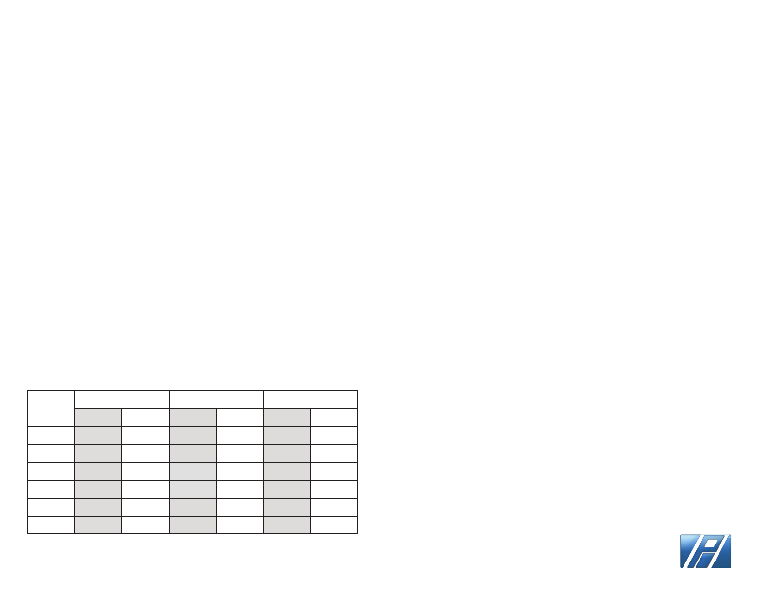
1. To avoid possible damage to the AT4K set INPUT, OUTPUT,
INDUCTOR, and POWER RANGE switches as outlined in the
chart below before applying transmitter power.
2. Begin tuning with your transmitter/amp feeding the tuner
set at a low output power setting (50-100 Watts max).
WARNING: DO NOT OPERATE THE
AT4K WITH THE COVER OFF.
TUNING
1. Select the band and frequency of desired operation.
2. Set TUNE and INDUCTOR controls to the suggested setting
before applying transmitter power (see chart). Actual settings
will vary from antenna to antenna.
3. Set your transmitter/amplier to 100-150 watts LOW output.
If your transmitter has a TUNE position, select that position.
4. Preset the INPUT, OUTPUT, and INDUCTOR values shown in
the chart. Select type of antenna feed, BALANCED or COAX.
BAND
INPUT OUTPUT INDUCTOR
SUGGESTED ACTUAL SUGGESTED ACTUAL SUGGESTED ACTUAL
5. Set POWER RANGE switch to 300 W (button out).
6. Set the OUTPUT SELECTOR switch to the position
matching your antenna connection. To tune your antenna,
the switch selection must be set to: COAX 1 TUNED, COAX 2
TUNED, or WIRE (BALANCED ANTENNA). Selecting COAX 1
DIRECT, COAX 2 DIRECT, or BYPASS bypasses the tuning
circuitry and tuning is not possible.
7. Key your transmitter and adjust the power level for a
reading of 100-150 watts on the FORWARD scale. Adjust the
INPUT, OUPUT, and INDUCTOR controls for a minimum
REFLECTED reading while maintaining a FORWARD reading
of 100-150 watts using your transmitter power control. Use
the supplied chart of approximate tuning control locations
for the dierent bands located at the back of the manual.
8. Read the SWR on the red scale at the point where the two
needles intersect. Repeat TUNING the input and antenna
controls until the lowest SWR reading is obtained.
9. When you have tuned your antenna to the best SWR, record
the settings of the INPUT, ANTENNA, and INDUCTANCE
controls on the chart above for future reference. When you
retune, use these settings as your starting point.
160 M
80 M
40 M
20 M
15 M
10 M
NOTE:
MAXIMUM INDUCTANCE is 0 (ZERO) on the turns counter.
59
57
53
44
21
21
MINIMUM INDUCTANCE is 229 (max turns clockwise).
64
66
77
43
19
12
81
169
206
210
222
229
Page 7
This procedure takes patience the rst time. The input
and antenna controls vary the capacitors and provide
ne adjustments, while the roller inductor crank
provides coarse adjustment.
PALSTAR
Page 8
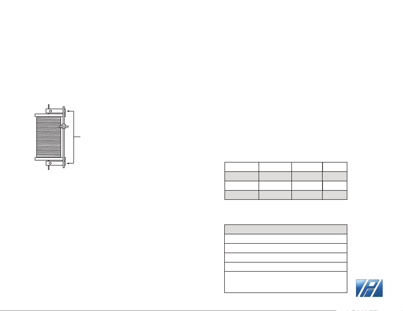
RESTORING THE INDUCTOR WHEEL
When approaching the end stops of the roller inductor
(readings of Zero or 229) SLOW DOWN. Slamming the
roller wheel into the mechanical end stops on either
end of the roller inductor will decrease the pressure of
the wheel against the wire wound on the ceramic form.
To RESTORE wheel pressure on
the inductor push down on the
at springs soldered to the
wheel shaft located on each
end of the shaft.
Notes:
1. A SWR of 1:1 is best, but an SWR as high as 2:1 may be acceptable. Check your
transmitter/amplier manual for details.
2. If you cannot get an acceptable SWR, lengthen or shorten your antenna and/or
feedlines and retune.\
3. If you get low SWR readings at more than one setting, use the setting that
gives:
- highest FORWARD power reading
- lowest REFLECTED power reading
- uses the largest capacitance (highest number) on the
INPUT and ANTENNA controls
- Adjust the largest capacitance (highest number) on the output control to
keep the losses low, and the voltage that would appear on the antenna capacitor
to within 5 kV.
4. Any time a new or dierent antenna is connected, it is necessary to repeat the
turning procedure for each antenna.
5. Once every 4-6 months clean the roller coil with Deoxit D5 contact cleaner and
a clean cotton cloth. Do not remove the conducting grease on the rod that guides
the roller wheel. Do not transfer any of the conducting grease from the rod to
the roller coil body, as this will contaminate the windings.
TROUBLESHOOTING
Your hear a spitting sound while tuning your AT4K at high
power.
You are probably tuning into an impedance that is on the
low side (20
transmitter/amplier power to a lower setting or change to a
higher antenna impedance by using a dierent antenna or
modifying the existing antenna.
As seen in the chart to the right, an antenna capacitance setting
that is too low under these conditions will result in excessively
high voltages, high losses, and poor eciency.
In the rst instance the tuner will arc and suer almost 16% loss,
of which 80% will be dissipated in the roller inductor.
1500 Watts into a 25 Ω load @ 3.5 Mhz
Ant Cap Inductor Voltage Loss
100pF
200pF
300pF
Power Specications (assuming single tone key down)
Antenna Impedance Max Power Rating
8 Ω - 15 Ω
15 Ω - 25 Ω
25 Ω - 50 Ω
50 Ω - 2000 Ω
Ω -40Ω). In this event, either reduce
11.7 μH
6 μH
4 μH
4550
2400
1600
500 watts (all bands)
1000 watts (all bands)
1500 watts (all bands)
160m - 2000 watts
80m - 15m - 2500 watts
10m - 1000 watts
(29.5 MHz max.)
16%
8%
6%
Page 8
PALSTAR
 Loading...