

Palstar 3CPX800A7 Owners Manual
COMMANDER II
2 METER VHF LINEAR AMPLIFIER
—————————————————————
Owner’s Manual
PALSTAR, INC.
Command Technologies Division
9676 N. Looney Road
Piqua, Ohio 45356
U.S.A.
Customer Service and Sales Telephone: 800-773-7931
Fax: 937-773-8003
E-mail: info@palstar.com

Table of Contents
Introduction 3
Inside View 4
Specifications 5
Unpacking Instructions 6
HV Transformer Installation 6-8
Safety Warnings and Precautions 9
Front & Rear Layout 10
Installation Preparation 11
Operating Procedure 12
Operating Hints 13
Typical Operating Conditions Table 13
Warranty, Service, and Returns 14
RF Deck Schematic 15
Control and Bias Board Schematic 16
High Voltage Power Supply Schematic 17
2

INTRODUCTION
The Commander II is a grounded grid class AB2 linear power amplifier that operates
on the Amateur 2 meter band (144 to 148 MHz).
A single CPI/Eimac 3CPX800A7 pulse-rated external anode triode with forced air
cooling and modern stripline circuitry ensures efficient and conservative operation.
The 6:1 ratio vernier reduction drives on all tuning controls allow smooth and easy
tune up, while the front panel input tuning control allows a higher input circuit "Q" for
excellent linearity and to present a low input VSWR to the exciter all across the entire 2
meter band.
An automatic delay circuit, for proper cathode conditioning before RF drive can be
applied, extends tube life. A 200 ohm resistor in the plate supply negative lead protects
the tube in the event of an arc.
The Commander II features a full compliment of control and metering functions for
easy on-air operation.
A dual primary power transformer allows 117VAC, 200VAC or 234VAC operation.
3
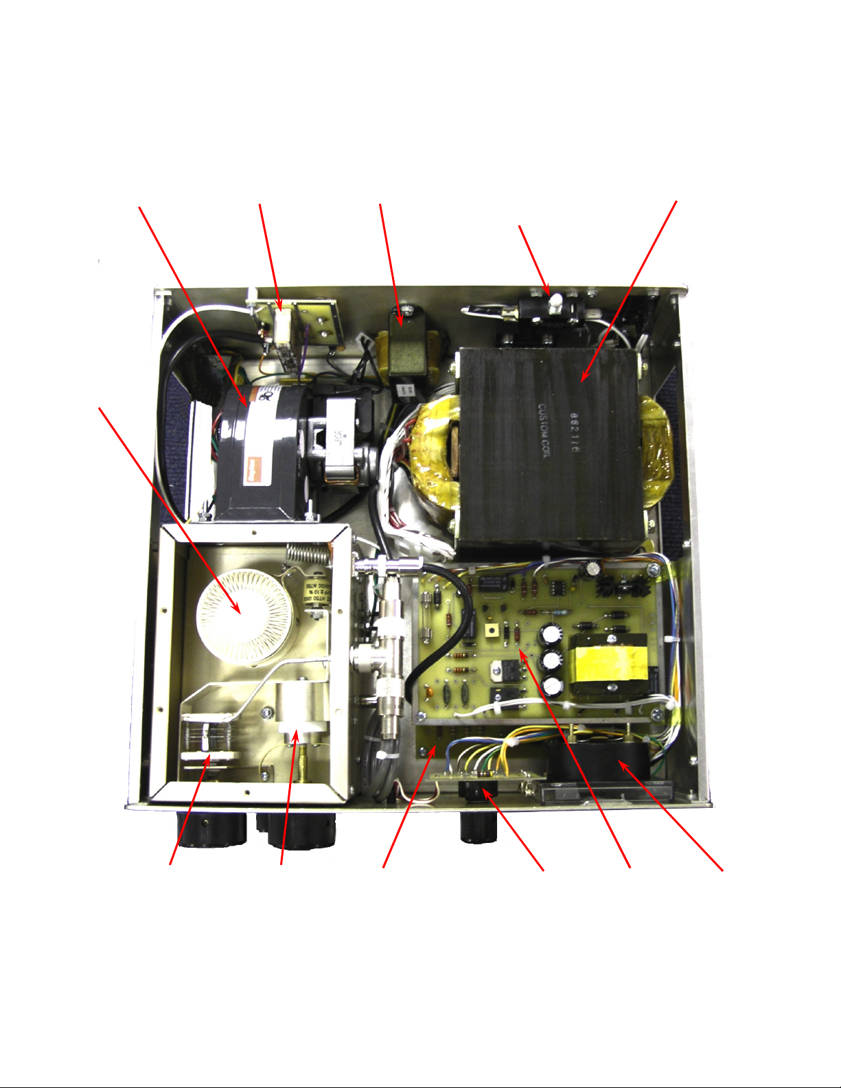
Commander II Inside Layout
Cooling
Blower
3CPX800A7
Triode Tube
T/R Relay
Board
Filament
Transformer
High Voltage
Interlock
Switch
High Voltage
Transformer
Load Tuning
Capacitor
Input Tuning
Piston Capacitor
High Voltage
Board
(underneath)
4
Multimeter
Switch
Control
Board
Multimeter

Specifications
Commander II
2 Meter VHF Linear Power Amplifier
• Frequency Range: 144 to 148 MHz.
• Modes: USB, LSB, RTTY, FM, CW.
• Power Requirements: 117/200/234VAC 50/60 Hz.
• RF Drive Power: 10 to 15 Watts nominal; 30 Watts maximum, for full 1 KW (CW) output.
• RF Output: +15db gain; > 650 Watts (USB, LSB); 450 Watts maximum. (FM or RTTY).
• Input Impedance: 50 Ohms unbalanced, front panel adjustable.
• Output Impedance: 50 Ohms nominal.
• Antenna Load (VSWR): 2:1 maximum.
• Harmonic Suppression: better than 60db down at rated output.
• Intermodulation Distortion: better than 35 dB down at rated output.
• Weight (with transformer): 60 lbs. (27.3 Kg).
• Cabinet Size: 14.5'' x 14.5'' x 6'' (36.8cm x 36.8 cm x 15.2 cm).
• Tube Compliment: one 3CPX800A7 ceramic metal triode.
• Cooling: pressurized chassis forced air.
• Antenna Relay: DPDT; .1 dB insertion loss.
• Fuse: Type SFE; 234VAC and 200VAC operation: 15 Amp; 117VAC operation: 30 Amp.
5
UNPACKING INSTRUCTIONS
Carefully remove your Commander II from its shipping carton making sure there is no dam-
age evident from shipping. If there is any damage, notify the delivering shipper immediately,
fully describing the damage.
Do not destroy the packing material, since it may be reusable later, should you require fac-
tory service, or need to transport the Amplifier for any other reason.
TRANSFORMER INSTALLATION
Due to its weight, the power transformer is shipped separately to prevent damage to the am-
plifier cabinet, and it must be installed by purchaser.
In order to install the HV transformer, both the top and bottom covers amplifier covers must
be removed. The small plastic bag (shipped with amplifier) contains the transformer mounting
hardware.
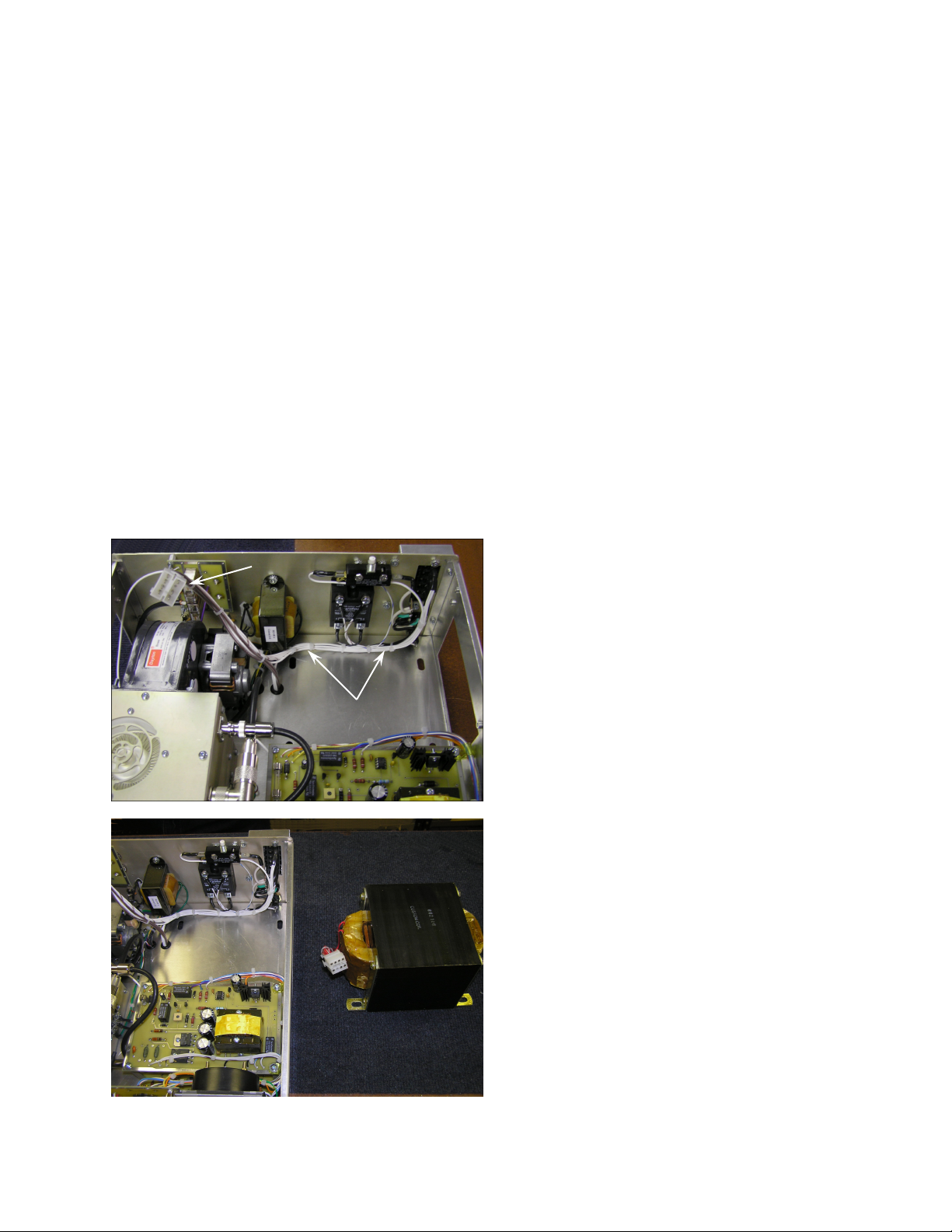
The following photographs illustrate the proper HV transformer installation:
2
This is the area the transformer
mounts in. Pay attention to the
wiring harness (1) at the rear and
be careful not to pinch any of the
wiring under transformer during
installation. Note that the connector (2) has been moved to the
1
side, out of the way
Position the HV transformer with
the wires and connector as
shown.
6
 Loading...