

Page 1

OWNER'S MANUAL
81CM CORDLESS REMOTE LCD TELEVISION & MONITOR
MODEL: TFTV836BK
PALSONIC CORPORATION PTY LTD
1 JOYNTON AVENUE
WATERLOO NSW 2017 AUSTRALIA
TEL: (02) 9313 7111
FAX: (02) 9313 7555
www.palsonic.com.au
PALSONIC CUSTOMER SERVICE
TELEPHONE
AUSTRALIA: 1300 657 888
Page 2
Important Safety Precautions
Warning
To prevent fire or shock hazard. Do not use this plug with an extension cord. Receptacle or other outlet unless the
blades can he fully inserted to prevent blade exposure to prevent fire or shock hazard. Do not expose this appliance
to rain or moisture.
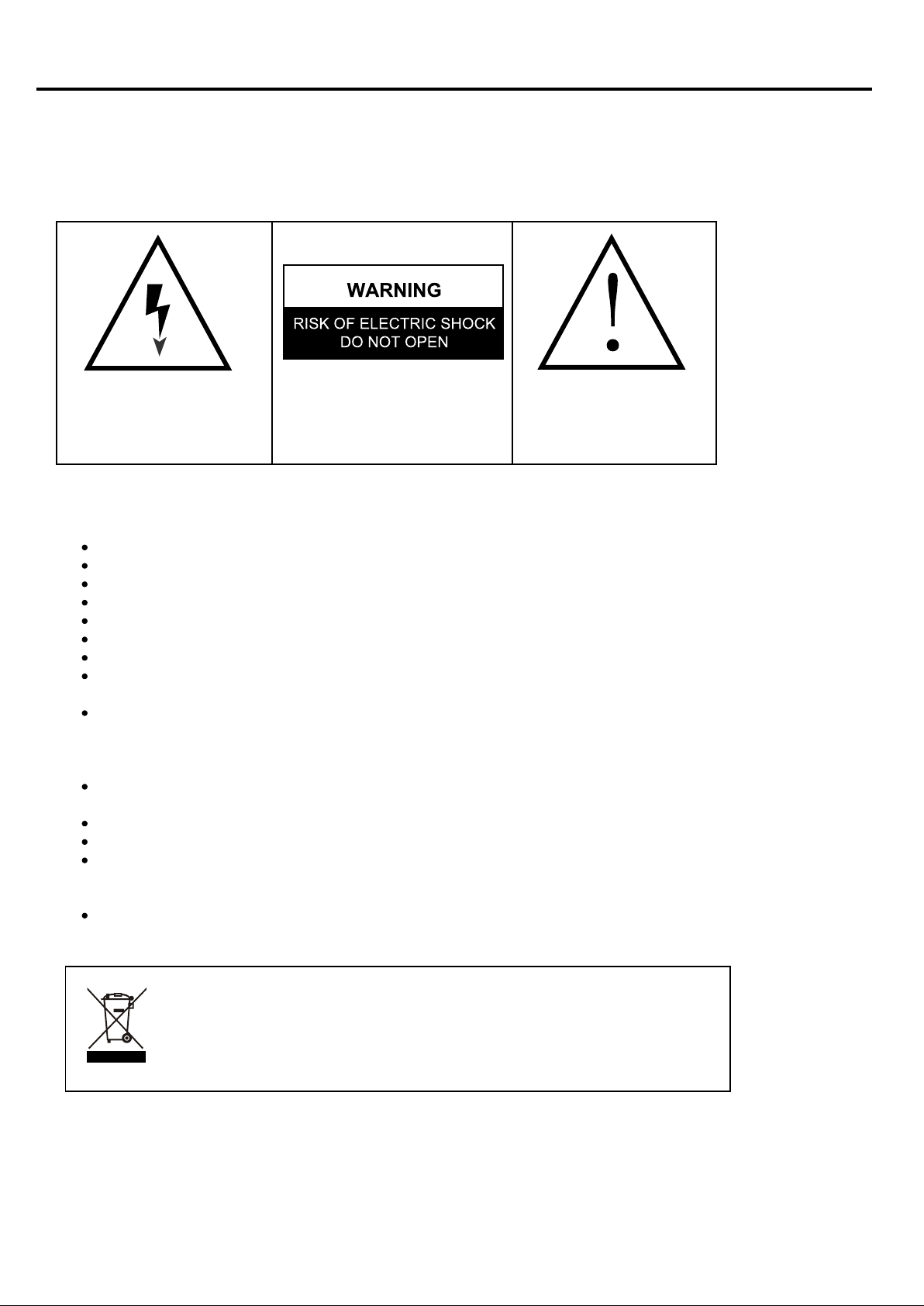
The lightning flash with arrowhead symbol
within an equilateral triangle, is intended to
alert the user to the presence of uninsulated
dangerous voltage within the product
enclosed that may be of sufficient magnitude
to constitute a risk of electric shock to persons.
WARNING: TO REDUCE THE RISK OF
ELECTRIC SHOCK, DO NOT REMOVE COVER
(OR BACK) NO USER SERVICEABLE PARTS
INSIDE, REFER SERVICING TO QUALIFIED
SERVICE PERSONNEL
The exclamation point within an equilateral
triangle is intended to alert the user to the
presence of important operating and
maintenance (servicing) instructions in the
literature accompanying the appliance.
Important Safety Precautions
Read these instructions.
Keep these instructions.
Heed all warnings.
Follow all instructions.
Do not use this apparatus near water.
Clean only with dry cloth.
Do not block any ventilation openings. Install in accordance with the manufacturer's instructions.
Do not install near any heat sources such as radiators. heat registers, stoves or other apparatus
(including amplifiers) that produce heat.
Do not defeat tile safety purpose of the polarised or grounding-type plug. A polarised plug has
two blades with one wider than the other. A grounding type plug has two blades and a third
grounding prong. The wide blade or the third prong is provided for your safety. If the provided
plug does not fit into your outlet, consult an electrician for replacement of the obsolete outlet.
Protect the power cord from being walked on or pinch particularly at plugs, convenience
receptacles, and the point where they exit from the apparatus.
Only use attachments/accessories specified by the manufacturer.
Unplug this apparatus during lightening storms or when unused for long periods of time.
Refer all servicing to qualified service personnel. Servicing is required when the apparatus has
been damaged in any way. such as power supply cord or plug is damaged. Liquid has been
exposed to rain or moisture, does not operate normally or has been dropped.
This appliance shall not be exposed to dripping or splashing water and that no object filled with
liquid such as vases shall be placed on the apparatus.
This symbol on the product or in the instructions means that your electrical and
electronic equipment should be disposed at the end of its life separately from
your household waste. There are separate collection systems for recycling in the
EU.
For more information, please contact the local authority or your retailer where
you purchased the product.
Page 3
WARNINGS AND CAUTIONS
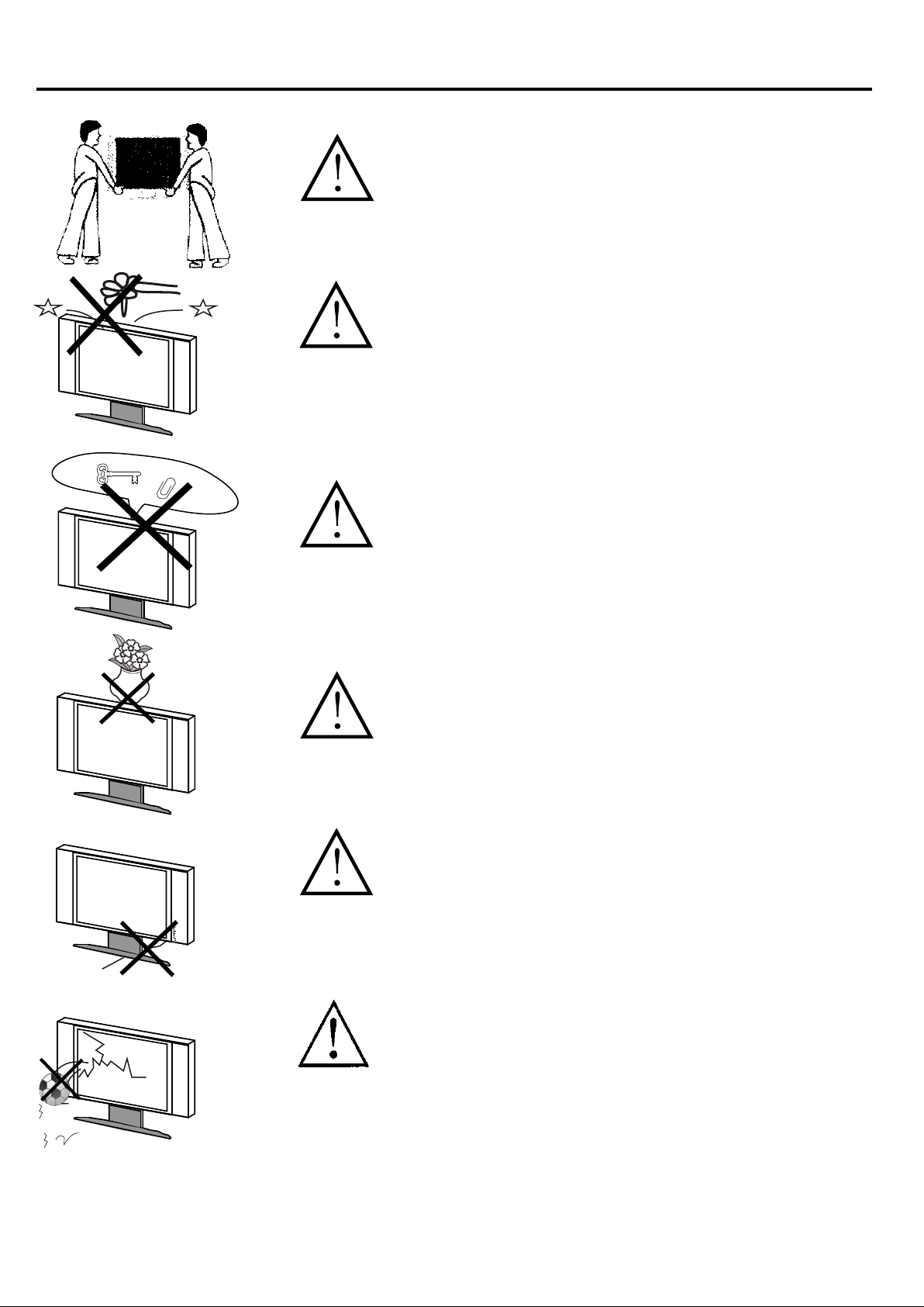
Caution
Carry the set requires two or more people
Caution
Do not drop or push objects into the television
cabinet slots or openings. Never spill any kind
of liquid on the television receiver.
Caution
Do not insert anything in the ventilation holes.
If metal or something flammable enters, it may
result in fire or electric shock.
Caution
Do not place objects on this unit. it may damage
the screen surface
Caution
Do not squash power supply cord under the
television receiver.
Caution
Do not throw anything at the set. The screen
glass may explode by impact and cause serious
injury.
2
Page 4
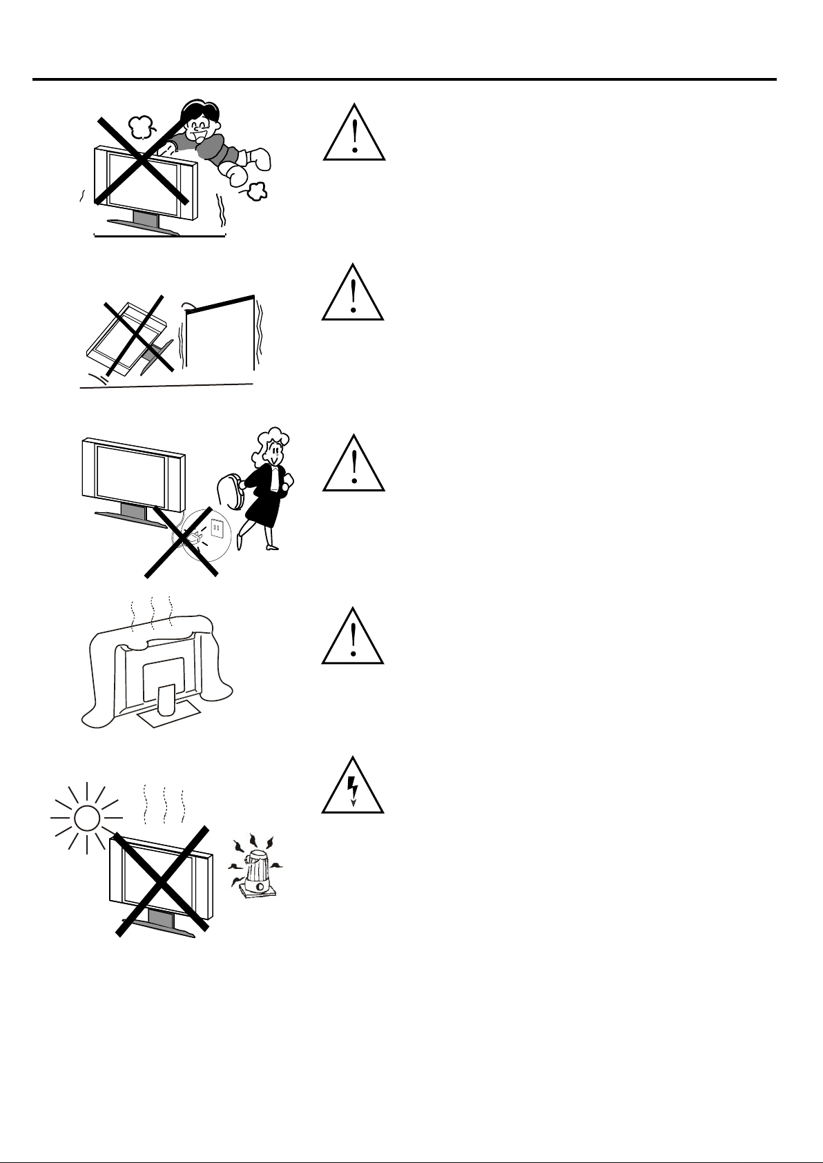
Warning and Cautions
Caution
Never stand on, lean on or push suddenly the
television or its stand. You should pay special
attention to children. Serious injury may result
if it should fall.
Caution
Do not place your television on an unstable cart,
stand, shelf or table. Serious injury to an
individual, and damage to the television, may
result it should fall.
Caution
When the television receiver is not used for an
extended period of time, it is advisable to
disconnect the AC power cord from the AC outlet.
Caution
Do not block the ventilation holes in the back
cover. Adequate ventilation is essential to prevent
failure of electrical component.
Warning
Avoid exposing the television receiver to direct
sunlight and other source of the heat.
Do not stand the television receiver directly on
other produces which give off heat. e.g. video
cassette players or Audio amplifiers.
Do not place naked flame sources, such as lighted
candle on the television. Do not expose the LCD
screen surface to the sun, it may damage the
screen surface.
3
Page 5
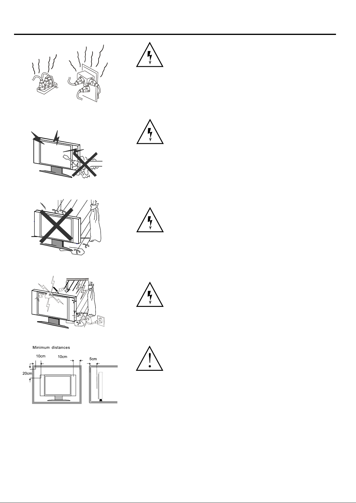
Warning and Cautions
Warning
Take care not to connect many appliances to the
same mains socket as this could result in fire or
electric shock. Do not place objects on this unit.
it may damage the screen surface.
Warning
High voltages are used in the operation of this
television receiver. Do not remove the cabinet
back from your set. Refer servicing to qualified
service personnel.
Warning
To prevent fire or electrical shock hazard, Do not
expose the television receiver to rain or moisture.
Warning
For you own safety, do not touch any part of the
set, main lead or aerial lead during lighting storms.
Caution
If the television is to be built into a Compartment
or similarly enclosed, the minimum distances
must be maintained.
Heat build-up can reduce the service life of your
television, and can also be dangerous.
4
Page 6

Table of Contents
Warnings and Cautions ......................................................................................................
Table of Contents ...............................................................................................................
Front/Back Panel Diagram .................................................................................................
Systems Connection ..........................................................................................................
Remote Controller ..............................................................................................................
Using the Remote Control ..................................................................................................
Remote Control Instruction ................................................................................................
Battery Installation .............................................................................................................
OPERATION INTRODUCTIONS .......................................................................................
Tuner on the LCD TV .........................................................................................................
Main Menu .........................................................................................................................
Teletext (optional) ...............................................................................................................
Nicam (optional) .................................................................................................................
HELP ..................................................................................................................................
SPECIFICATION ................................................................................................................
2
5
6
7
9
9
9
9
10
10
10
20
21
22
23
5
Page 7
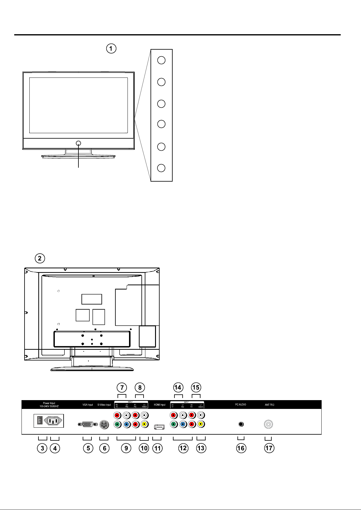
Front / Back Panel Diagram
1. LCD TV Button:
STANDBY (on/off)
Button
VOL -
VOL +
CH -
CH +
MENU
SOURCE
STANDBY: Turn on/off
LCD TV
VOL+/-: Adjust Volume
CH+/-: Select channel
MENU: Into or exit from menu (Use
CH+/- button select item. use VOL+/button to adjust item)
SOURCE: Source select
2. BACK PANEL:
3. Power Switch: Turn on/off
LCD TV main power
4. Power Socket
5. VGA Input
6. S-VIDEO Input
7. Audio Input (YPbPr 2)
8. Audio Input (Video 2 /S-VIDEO)
9. YPbPr 2 Input
10. VIDEO 2 Input
11. HDMI Input
12. YPbPr 1 Input
13. VIDEO 1 Input
14. Audio Input (YPbPr 1)
15. Audio Input (Video 1)
16. PC Audio Input
17. ANTENNA
6
Page 8
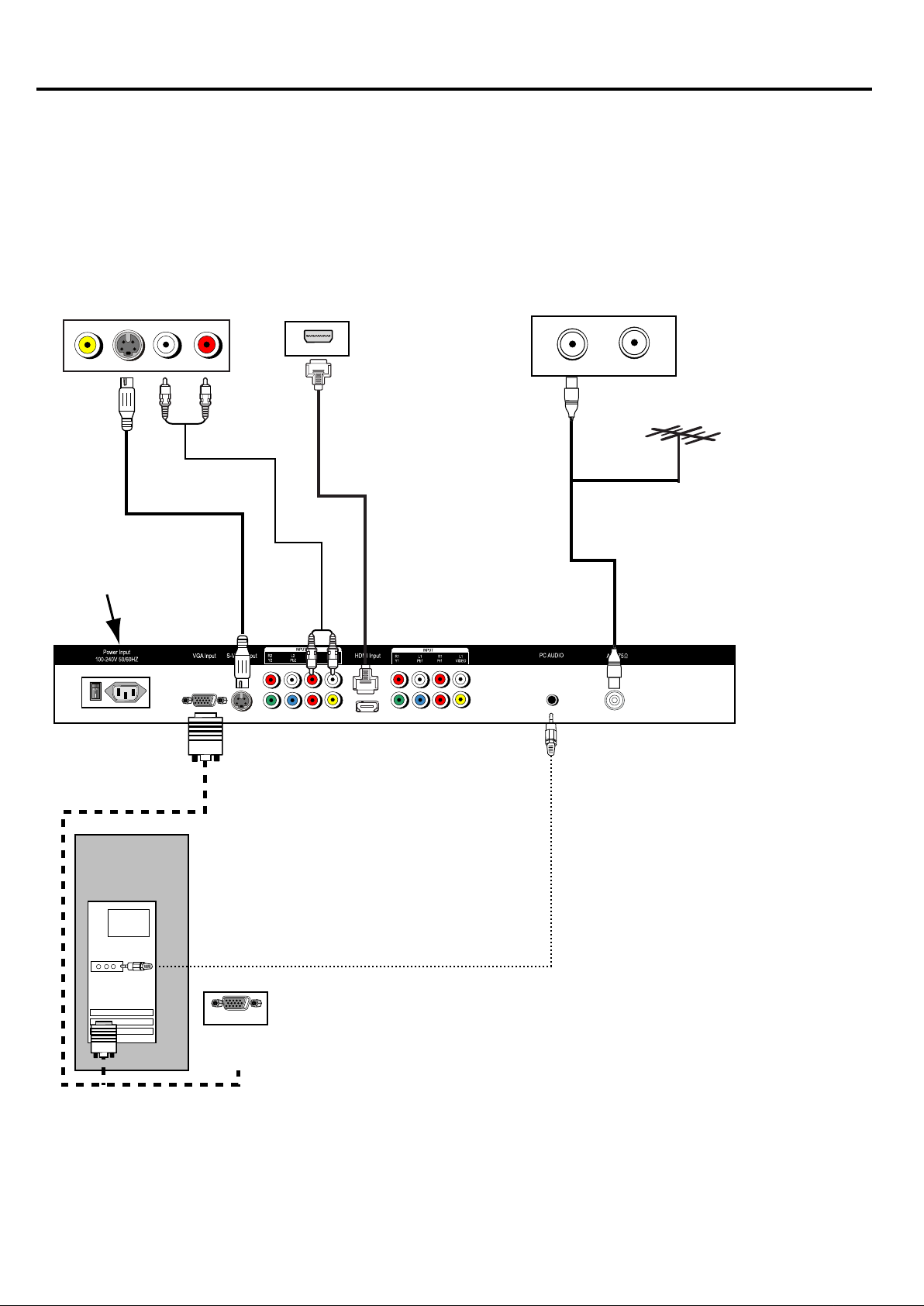
SYSTEMS CONNECTIONS
CONNECTION:
INPUT/OUTPUT JACK AS FOLLOWS: ANT Input, VIDEO Input. S-VIDEO Input,
VGA Input, PC (audio) Input. HDMI, Y Pb Pr 1 Input, Y Pb Pr2 Input
CONNECT POWER: Connect the 100-240V~50/60Hz power input of the LCD TV.
Notice:
1. Must connect properly, especially the plug should be inserted to the bottom.
2. This picture is only for your reference.
A: VGA, PC (AUDIO) IN, HDMI, S-VlDEO, ANTENNA CONNECT
DVD VIDEO output
VIDEO S-VIDEO L R
AUDIO OUTPUT
100-240V 50/60Hz
INPUT
HDMI output
HDMI
TV signal output
TV ANT
TV ANT
ANTENNA
PC
AUDIO CABLE
VGA OUTPUT
DVD VGA
OUTPUT
7
Page 9

SYSTEM CONNECTION
B: Y Pb Pr 1, Y Pb Pr 2, VIDEO 1, VIDEO 2, CONNECT and AUDIO CONNECT
100-240V 50/60Hz
INPUT
Y Pb Pr 2 AUDIO
INPUT
VIDEO 2 AUDIO
VIDEO 1 AUDIO
INPUT
INPUT
Y PB PR 1 AUDIO INPUT
DVD Y Pb Pr output 2 DVD VIDEO 2
DVD Y Pb Pr output 1
8
DVD VIDEO 1
Page 10

Remote Controller
Using the Remote Control
Unless stated otherwise, the remote control
can operate all the features of the LCD TV
Always point the remote control directly at
the remote sensor in the front of the LCD TV.
Remote control instruction
1.
Mute: Mute ON/OFF
2.
0-9: Digital key
3.
HDMI: Switch to the HDMI mode
4.
FOUR COLOUR BUTTONS:
There are four colour buttons in the last row of
the remote controller. They are red, green,
yellow and blue from left to right. By pressing
these buttons, you can enter relative pages
quickly which is is indicated in the last row of
current teletext page.
5.
16:9: Adjust aspect setting
6.
TXT/CC: Display TELETXT signal, mixing
teletext page with TV signal, close teletext
7.
PICTURE: Call out picture mode menu.
8.
and adjust the picture mode
9.
VOL-: Volume down
SOUND: Call out sound mode menu. and
adjust the sound mode.
10.
LUCIDTY: Switch to the Teletext with
mix mode
11.
INDEX: Request index page
12.
Cancel: Change display size
13.
HOLD: Toggle hold on or off for current
display page
14.
SIZE: Remove the Teletext & program
15.
REVEAL: Show the hidden words
16.
SUBPAGE: Some page attach sub-page,
press "SUB-PAGE" button to view the
sub-pages.
17.
CH-: Channel down
18.
EXIT: Exit the menu
19.
OK ( ): to confirm that what you
choose.
20.
VOL+: Volume up
21.
CH+: Channel up
22.
MENU: The button to enter into or exit
from menu
23.
Display: Call out info menu
24.
: Switch to the last channel
25.
SOURCE: Input source selection
26.
STILL: Pause picture
27.
NICAM/A2: Nicam function
28.
Sleep: Set the sleep time
29.
Power: Turn the power on when pressed
Battery Installation
Remove the battery compartment lid on the
rear of the remote control by sliding the lid
down, then off. Put two AAA batteries inside
the battery compartment with their + and ends aligned as indicated.
Do not mix old and new batteries or different
types of batteries. Replace the battery compartment lid. Slide the lid until you hear it
click into place.
1
2
3
HDMI
4
5
6
7
8
9
10
11
12
13
29
28
27
26
25
24
23
22
21
20
19
18
17
16
15
14
9
Page 11

OPERATION INTRODUCTIONS
Tuner on the LCD TV
1. Connect the 100-240V~50/60Hz power input of the LCD TV
2. Press the POWER button to turn or turn off.
3. When the power is on, press the SOURCE button choose the input mode you want.
Remark:
TV - Y PbPr 1 - Y PbPr 2 - VIDEO 1 - VIDEO 2 - S-VIDEO - HDMI - VGA (PC)
3. The OPTIONS SETTING menu allows you to alter the picture adjustment. Press
or button to highlight the item you want to alter. Press or to select the item you want to
alter, then press or button to adjust it.
Note: The item of selected is highlight when press or button.
VGA INPUT:
Resolution
Vertical frequency (Hz)
640x480
60/75
800x600 1024x768
60/75
60/75
HDTV (Y Pb Pr) INPUT:
Resolution
Vertical frequency (Hz)
480i 480p 576i 576p 1080i 720p
60 60 50 50 50/60 50/60
HDMI INPUT:
Resolution
Vertical frequency (Hz)
480i 480p 576i 576p 1080i 720p
60 60 50 50 50/60 50/60
1. Menu Structure and Navigation
1. Press the MENU button to invoke the main menu as shown.
2. Use button to select the main menu icon, the focused icon will be shown as a protruded
button.
3. Press the button to goto the corresponding menu.
4. Press the button to select menu item, the focused item will be highlighted in yellow.
5. Press the button to select the selection, adjust item value, or enter sub menu.
6. Exit the OSD mode by either of the following methods:
a) Wait for Time out (60 seconds default)
b) Press the EXIT button.
Contrast
Brightness
Saturation
Sharpness
Colour Temp.
DNR
MENU
Back
EXIT
PICTURE
50
50
55
+10
Off
Exit Menu
10
Page 12

OPERATION INTRODUCTIONS
Picture Menu
PICTURE
Contrast
Brightness
Saturation
Sharpness
Colour Temp.
DNR
MENU
Back
EXIT
Exit Menu
1. Contrast
The scale of control should be 0 -100. When it is set to 0, the image should not be 'Dark'
2. Brightness
The scale of control should be 0 -100. When it is set to 0, the image should not be 'Dark'
56
59
55
+10
Off
3. Saturation
The scale of control should be 0 -100.
4. Sharpness
The scale of control should be (-50) - (+50).
5. Colour temperature
The selection of control is Normal, Warm and Cool.
6. DNR
The selection of control is Off, Auto, Low, Mid and High.
7. Advanced
Press the button to enter the Advanced Picture Menu.
Advanced Picture Menu
Flesh Tone
Green Tone
Blue Tone
Film Mode
MENU
Back
EXIT
Advanced
Off
Off
Off
Auto
Exit Menu
11
Page 13

1. Flesh Tone
The scale of control should be a ON/OFF.
2. Green Tone
The scale of control should be ON/OFF.
3. Blue Tone
The scale of control should be ON/OFF.
4. Film Mode
selection of control is Off and Auto.
Sound Menu
Balance
Volume
AVL
Surround
Equalizer
OPERATION INTRODUCTIONS
SOUND
0
17
Off
Normal
MENU
Back
EXIT
Exit Menu
1. Balance
a. This option adjusts the balance of sound between left and right speakers.
b. The scale of control should be (-50) - (+50).
c. When set the value towards (-50), the sound tends to left. When set the value towards
(+50), the sound tends to right.
2. Volume
This option adjusts the volume 0-100.
3. AVL
This option adjusts the avl ON/OFF.
4. Surround
This option adjusts the surround mode off, normal, spatial.
5. Equaliser
This option adjusts the equaliser mode.
100 Hz
330 Hz
1 kHz
33 kHz
10kHz
MENU
Back
EXIT
Equalizer
+13
+16
+8
+20
0
Exit Menu
12
Page 14

OPERATION INTRODUCTIONS
Setup Menu
SET UP
Channel
Colour
Sound
Skip
Auto Search
Manual Search
MENU
Back
EXIT
Exit Menu
The item "Program" changes the current program number.
Other items change the current program settings. After pressing the the setting is stored.
The MENU button will NOT save the current settings and the previous setting will be
restored.
01
AUTO
I
Off
048.25 MHz
1. Channel Number
This item is to change the current program number.
a. Press the button to change the current program number.
b. Press number button to directly input the current program number.
2. Colour
a. This item is to change the colour system of the current program.
b. The selection of control is AUTO, PAL, SECAM.
3. Sound system
a. This item is to change the sound system of the current program.
b. The selection of control is I, D/K, L, B/G.
4. Skip
a. This item is to change the skip option of the current program.
b. The selection of control is On and Off.
c. When the skip option of the current program is On, user can not get to this program by press
channel +/- but the direct number button is working.
5. Auto Search
a. Press the button to start auto tuning.
b. Press the MENU button to go back to Setup Menu.
c. Press the EXIT button to exit all Menus.
6. Manual Search
a. This item is to change the frequency value of the current program.
b. Press the button to start manual search, the value shows the current frequency.
c. Press number button to directly input the frequency value.
13
Page 15

OPERATION INTRODUCTIONS
7. AFT
a. This item is to change the AFT value of the current program.
b. The selection of control is On, Off. or a value between (-15, +15).
c. When the AFT option of the current program is On, system automatically track the current
program frequency by monitoring AFT level. When this option is Off, this function is disabled.
When set to a number, the frequency departure from the searched frequency.
8. Label
a. This menu is to change the program label of the current program.
b. Press the button to change character position.
c. Press the button to change character.
There are 7 character positions. The available characters are:
'A'-'Z' '(' ')' '*' '+', ',' '-' 'o' '/' '0'-'9'.
9. Program Edit
a. This menu is to edit the program storage.
b. Press the button to select program.
c. Press the button to choose one program to be moved.
After user chooses a program, the menu changes like this:
a. The chosen program is moved to right, so user can now:
b. Press the button to select a position.
c. Press the button to insert the chosen program and swap two programs.
14
Page 16

Timer Menu
Current Time
Off Timer
On Timer
On Channel
Timer Mode
OPERATION INTRODUCTIONS
TIMER
00 : 07
00 : 03
00 : 00
01
Off
MENU
Back
EXIT
Exit Menu
1. Current Time
This option adjusts the clock.
2. Off Time
This option adjusts the automatically power off timer. The unit is minute.
Once the timer is set to a non-zero time, it is enabled and the number decreases every minute.
When the timer runs to zero, it triggers the power off action.
a. Press the button to change the timer number.
b. Continuously press down the button to change the timer number by 30 minutes.
c. Press number button to directly input the timer number.
3. On Time
This option adjusts the automatically power on timer. The unit is minute.
Once the timer is set to non-zero time, it is enabled and the number decreases every minute.
When the timer runs to zero, it triggers the power on action (in power off status) or the program
change action (in power on status).
a. Press the button to change the timer number.
b. Continuously press down the button to change the timer number by 30 minutes.
c. Press number button to directly input the timer number.
4. On Channel
This option adjusts the automatically power on program position.
The position is the program that system changes to when the on timer triggers.
a. Press the button to change the program position.
b. Continuously press down the button to change the program position by 10.
c. Press number button to directly input the program position.
5. Timer Mode
This option adjusts the off time and on time once, every, off mode.
15
Page 17

Timer Menu
Current Time
Off Timer
On Timer
On Channel
Timer Mode
OPERATION INTRODUCTIONS
TIMER
00 : 07
00 : 03
00 : 00
01
Off
MENU
Back
EXIT
Exit Menu
1. Current Time
This option adjusts the clock.
2. Off Time
This option adjusts the automatically power off timer. The unit is minute.
Once the timer is set to a non-zero time, it is enabled and the number decreases every minute.
When the timer runs to zero, it triggers the power off action.
a. Press the button to change the timer number.
b. Continuously press down the button to change the timer number by 30 minutes.
c. Press number button to directly input the timer number.
3. On Time
This option adjusts the automatically power on timer. The unit is minute.
Once the timer is set to non-zero time, it is enabled and the number decreases every minute.
When the timer runs to zero, it triggers the power on action (in power off status) or the program
change action (in power on status).
a. Press the button to change the timer number.
b. Continuously press down the button to change the timer number by 30 minutes.
c. Press number button to directly input the timer number.
4. On Channel
This option adjusts the automatically power on program position.
The position is the program that system changes to when the on timer triggers.
a. Press the button to change the program position.
b. Continuously press down the button to change the program position by 10.
c. Press number button to directly input the program position.
5. Timer Mode
This option adjusts the off time and on time once, every, off mode.
16
Page 18

AV Setup Menu
Colour
OPERATION INTRODUCTIONS
SET UP
AUTO
MENU
Back
EXIT
Exit Menu
1. Colour
a. This item is to change the colour system of the current AV source.
b. The selection of control is AUTO, NTSC, PAL, SECAM, PAL60, NTSC443.
HDTV /HDMI Setup Menu
SET UP
H Position
V Position
Reset
0
0
MENU
Back
EXIT
Exit Menu
1. H Position
The scale of control should be (-10) - (+10).
2. V Position
The scale of control should be (-10) - (+ 10).
3. Reset
Press the button to reset settings.
17
Page 19

PC Setup Menu
H Position
V Position
Auto Sync
Phase
Clock
OPERATION INTRODUCTIONS
SET UP
0
0
0
0
0
MENU
Back
EXIT
Exit Menu
1. H Position
The scale of control should be (-10) - (+10).
2. V Position
The scale of control should be (-10) - (+10).
3. Auto Sync
a. This item is to automatically setup the position settings of the current PC signal.
b. Press the button to start auto sync.
4. Phase
a. This option adjusts the phase of the PC signal.
b. The scale of control should be (-10) - (+10).
S. Clock
a. This option adjusts the clock of the PC signal.
b. The scale of control should be (-10) - (+10).
Volume Menu
The Volume Menu should appear at the bottom part of the screen.
a. Use button to call out volume menu, and adjust the volume value.
b. Press the /EXIT button to exit volume menu.
c. The scale of control should be 0 -100.
18
Page 20

OPERATION INTRODUCTIONS
Picture Mode Menu
Dynamic
The Picture Mode Menu should appear at the left bottom part of the screen.
Use the following keys to navigate through the picture mode menu:
a. Use PlC MODE button to call out picture mode menu, and adjust the picture mode.
b. Press the /EXIT button to exit picture mode menu.
c. The selection should be Soft, Standard, User and Vivid.
When user changes anyone of Contrast, Brightness, Saturation and Sharpness settings, the
picture mode changes into Memory automatically and the current picture settings are stored
into EEPROM memory part.
Sound Mode Menu
Theater
The Sound Mode Menu should appear at the left bottom part of the screen.
a. Use SND MODE button to call out sound mode menu, and adjust the sound mode.
b. Press the /EXIT button to exit sound mode menu.
c. The selection should be User, Theater, Music and News.
When user changes any one of Bass and Treble settings. The sound mode changes into Memory
automatically and the current sound settings are stored into EEPROM memory part.
Info Menu
The Info Menu should appear at the left top part of the screen.
The lnfo Menu appears when:
a. Signal changes.
b. TV channel changes.
c. Source changes.
d. User presses the DISPLAY button to call out info menu.
User can press the /EXIT button to exit info menu.
Source Switch Menu
Source Select
TV
Y Pb Pr1
Y Pb Pr2
VIDEO 1
VIDEO 2
S-VIDEO
VGA
HDMI
a. Press SOURCE button to call out source switch menu.
b. Use button to select source.
c. Press the button to switch into the corresponding source, or press EXIT button to
exit source switch menu.
19
Page 21

OPERATION INSTRUCTIONS
TELETEXT (Optional)
Teletext features may vary depending on the Broadcasting Companies and is only available
if the channel selected is transmitting Teletext. Pressing the Picture button whilst in Teletext
operation will switch the current status to TV When in Teletext mode, the volume may still
be altered to desired listening level, after pressing VOL+/VOL- or MUTE button.
Page Selection
Pages can be selected in following ways:
By entering the page number, using 0-9 button on the remote control.
Size Button
Press Size to change display size: normal => large top => large button => normal.
Reveal Button
Press Reveal to reveal hidden words e.g. Quiz page answers. Press again to hide.
RED / GREEN / YELLOW / CYAN Buttons these four buttons correspond to the differently
coloured subjects.
Hold Button
Press Hold to remain the Teletext page when viewing multi-page information Press again to
return to automatic page update.
Index Button
Press Index to return to the main index page.
Depending on the way information is transmitted, this may have to be pressed more than
once to return to the main index page.
Subpage Button
When Teletext information exceeds more than one page, it may take some time for the
automatic changing of the sub pages to reach the sub page you require.
It is possible to enter your required sub page and continue watching the normal programme
until the correct sub page is found.
Select the required page number using buttons 0-9.
If the top of the page indicates that sub pages are being transmitted yet the page dose not
change, then the number at the top of the page is there to indicated that the broadcaster has
updated the page's contents, there are no sub pages.
Press Subpage, page number/----will be displayed at the Button right of the screen.
Enter desired sub page number before the page number/----disappears. To select page 6
enter 0, 0,0 and 6.
Text Button
Press Text to enter Teletext mode and only the text page can be visible.
Lucidity Button
Press Lucidity to enter Teletext mode and both the TV picture and text page can be visible.
Cancel Button
Press Cancel to turn off the Teletext.
20
Page 22

Operation Introductions
NICAM (Optional)
Press the NICAM/A2 button:
Usually set to stereo to provide the best reproduction, but if reception deteriorates or if the
service is not available then switch to Mono.
Mono (MI) and (M2) can also be selected if a mono signal is being transmitted.
21
Page 23

Help
No picture and no sound
Has picture but no sound Check audio cable and audio volume
Picture in black and white
or colour problem
Picture or sound interference
No signal display
Remote control problem
Check power supply and cable connection
Make sure the power button is ON
Check for correct setting for brightness and
contrast ratio
Make sure TV was not muted
Adjust colour setting
Check if the TV tuner format selection is
correct
Check if TV is too close to other electronic
devices for potential interference.
Check if selected input source and connection
Check if the selected input source is working
Check battery
Remote does not aim at TV remote signal
receiver
Snowy picture with noise
Check if there is obstacle between remote and
TV
Remote is too far away from TV or the angel is
too sharp
Adjust antenna location and angel for better
reception
Check antenna location and angel for better
reception
Check PC or the connected device for correct
frequency and bandwidth
22
Page 24

Specifications
LCD:
View angle:
PC input:
Resolution:
TV system:
Channel amount:
Input:
Speaker:
ANTENNA:
Power supply:
Power Consumption:
Accessories
This user manual is for reference only. Specifications are subject to change without notice.
81cm LCD
Horizontal view angle: 176
Vertical view angle: 176
Vertical frequency: 60/75Hz
640x480, 800x600, 1024x768
(best resolution 1024x768)
PAL B/G,D/K
100
HDMI, VGA (PC), YPbPr 1, YPbPr 2,
VIDEO 1, VIDEO 2, S-VIDEO, PC Audio,
ANTENNA
10W x 2 (Impedance 8ohm)
75 ohm
100-240V~50/60
160W
Remote controller, common AAA battery
23
Page 25

PALSONIC CORPORATION PTY LTD
1 JOYNTON AVENUE
WATERLOO NSW 2017 AUSTRALIA
TEL: (02) 9313 7111
FAX: (02) 9313 7555
www.palsonic.com.au
PALSONIC CUSTOMER SERVICE
TELEPHONE
AUSTRALIA: 1300 657 888
 Loading...