

Palsonic 86WSHDA, MODEL 76WSHDA 1 Owner's Manual

PALSONIC CORPORATION PTY LTD
1 JOYNTON AVENUE
WATERLOO NSW 2017 AUSTRALIA
TEL: (02) 9313 7111
FAX: (02) 9313 7555
www.palsonic.com.au
PALSONIC CUSTOMER SERVICE
TELEPHONE
AUSTRALIA: 1300 657 888
76CM/86CM WIDE SCREEN HDTV READY
MODEL: 76WSHDA
: 86WSHDA
OWNER'S MANUAL
Type Tested
Electrical
Safety
AS/NZS 3250 Lic 4166
Standards Australia
APP No: N18748

Contents
Congratulations on your purchase of Palsonic's HDTV ready.
We recommend that you thoroughly read this manual before use to fully enjoy the many functions
and excellent effects of this equipment.
Retain this manual in an easily accessible location for future reference.
* Screen displays and illustrations in this manual may differ from the actual ones for better
visibility.
Contents
Cautions for safety ....................................................................................
Locations of controls .................................................................................
Remote controller ......................................................................................
Installation .................................................................................................
Basic operation .........................................................................................
Operation in RF mode ..............................................................................
Channel presetting ................................................................................
Channel selection .................................................................................
Picture adjustment ................................................................................
Sound adjustment .................................................................................
Timer setting .........................................................................................
System setup ........................................................................................
Operation in VIDEO mode ........................................................................
Operation in HDTV mode .........................................................................
1. YPbPr ..............................................................................................
2. XGA mode .......................................................................................
Display mode setting ................................................................................
Troubleshooting Guide .............................................................................
Specifications ...........................................................................................
1
3
5
7
11
13
13
17
18
22
24
25
27
28
28
29
34
35
36

Cautions for safety
Cautions for safety
1
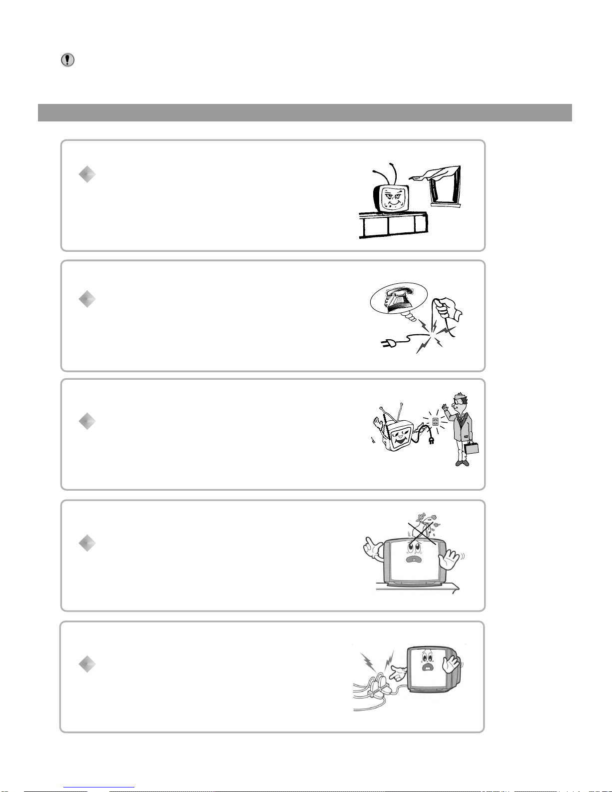
When any unusual situation occurs, turn off the
power supply at once and remove the plug from the
wall outlet. Contact a qualified service department in
your local area.
Normally, the screen surface should not be
cleaned; however, if it is essential, clean the
surface with a soft, dry cloth while the TV is turned
off. Never use any detergent cleaners to clean the
surface. The screen surface may be scratched if a
hard cloth is used.
Avoid exposing the set to direct sunlight and other
sources of heat to prevent damage to the cabinet
and components.
Do not expose the TV set to rain or excessive
moisture. Avoid using the set in very warm or
damp places and never use it in a bathroom.
High voltage exists in this TV set. Do not remove the
cover.
2
Note: This set can operated on an AC power of 240V, 50Hz. You must not use
a power supply of any other type.
Don't overload wall outlets; extension cords, or
integral convenience receptacles as this can result
in a risk of fire or electric shock.
Do not cover the ventilating hole in the cabinet
Keep a space of more than 10cm from the walls to
the TV set to ensure adequate ventilation.
If the power cord or the plug is damaged contact a
qualified service department for service.
When the TV set is to be left unattended for a long
period of time, turn off the power supply and remove
the plug from the wall outlet.
Don't try to push anything into the cabinet or place
any vessel with water on the TV set.
Location of controls
Front view/Side view/Back view
3
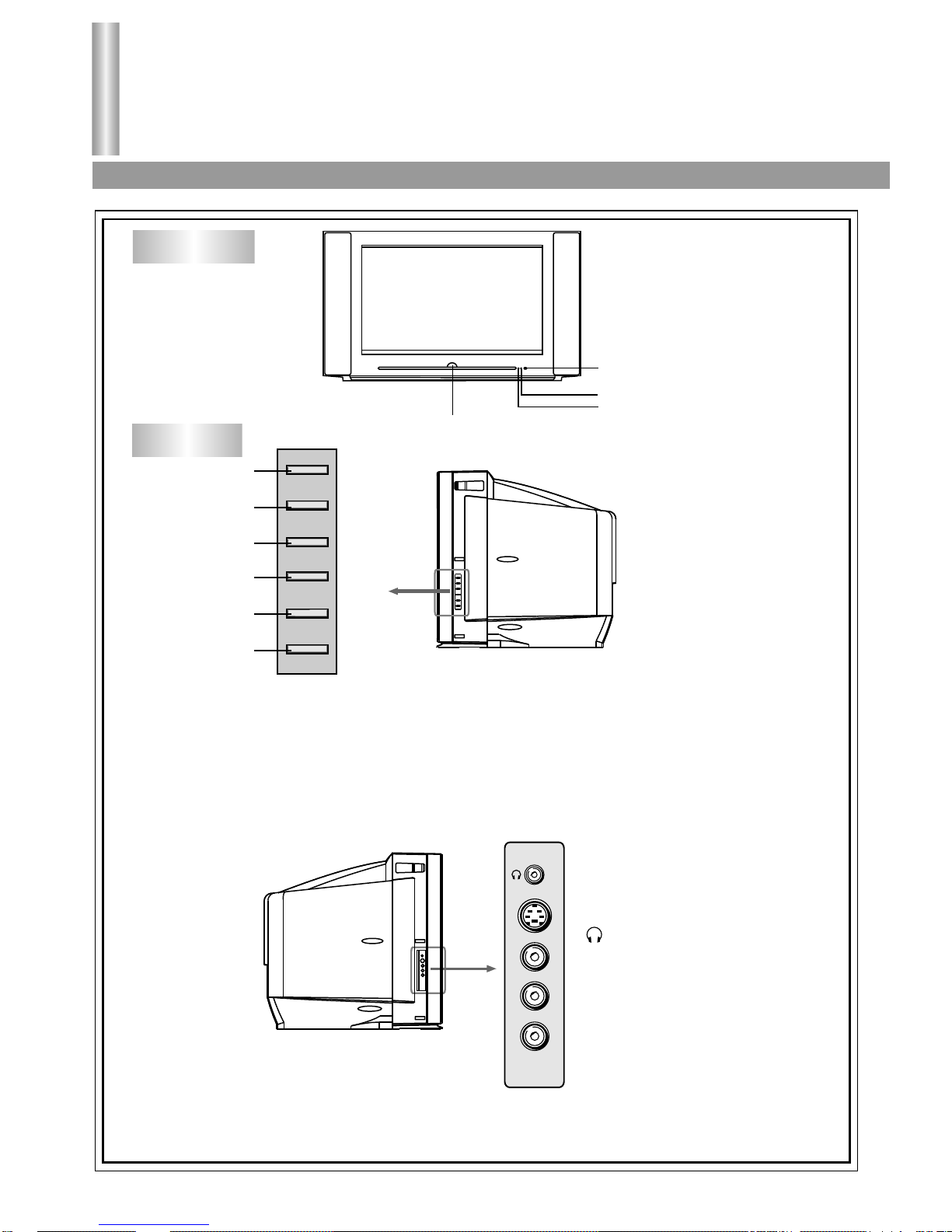
Front view
POWER SWITCH
INDICATOR
INDICATOR
REMOTE SENSOR
Side view
1. TV/AV button: Open the signal source selection menu.
2. CH- button: Select a lower position number.
3. CH+ button: Select a higher position number.
4. MENU button: Enter into the menu.
5. VOL- button: Lower the volume
6. VOL+ button: Raise the volume.
TV/AV
CH-
CH+
MENU
VOLVOL+
1
2
3
4
5
6
S-VIDEO
VIDEO
L/MONO
R
AV3 IN
: Headphone jack
AV3 input terminals
{S-VIDEO, VIDEO,
AUDIO L/MONO, R}
Y
Y
XGA
C
B
P
B
C
R
P
R
S-VIDEO
L/MONO
R
RF IN
3
4
5
6
AV1
IN
AV2
IN
AV
OUT
HDTV IN
DVD IN
VIDEO
1
4
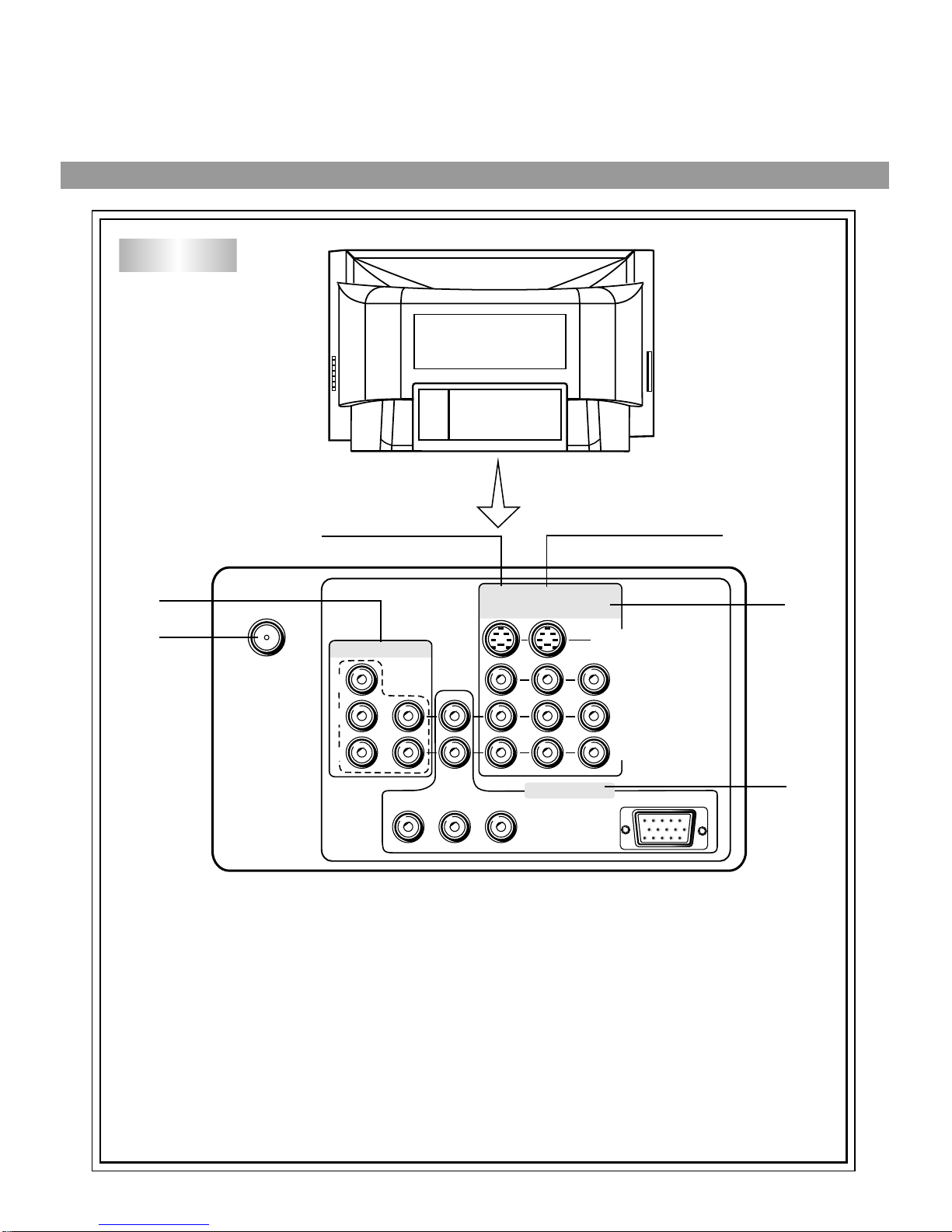
1. Antenna input
2. DVD input terminals { VIDEO: Y, CB, CR, AUDIO: L/MONO, R}
3. AV1 input terminals { S-VIDEO, VIDEO, AUDIO: L/MONO, R}
4. AV2 input terminals { S-VIDEO, VIDEO, AUDIO: L/MONO, R}
5. AV output terminals { VIDEO, AUDIO: L/MONO, R}
6. HDTV input {Y, PB, PR, XGA, AUDIO: L/MOMO, R}
Back view
2
Open the signal source
selection menu
Open/close the menu
HDTV/TV
Remote Controller
Remote controller
5
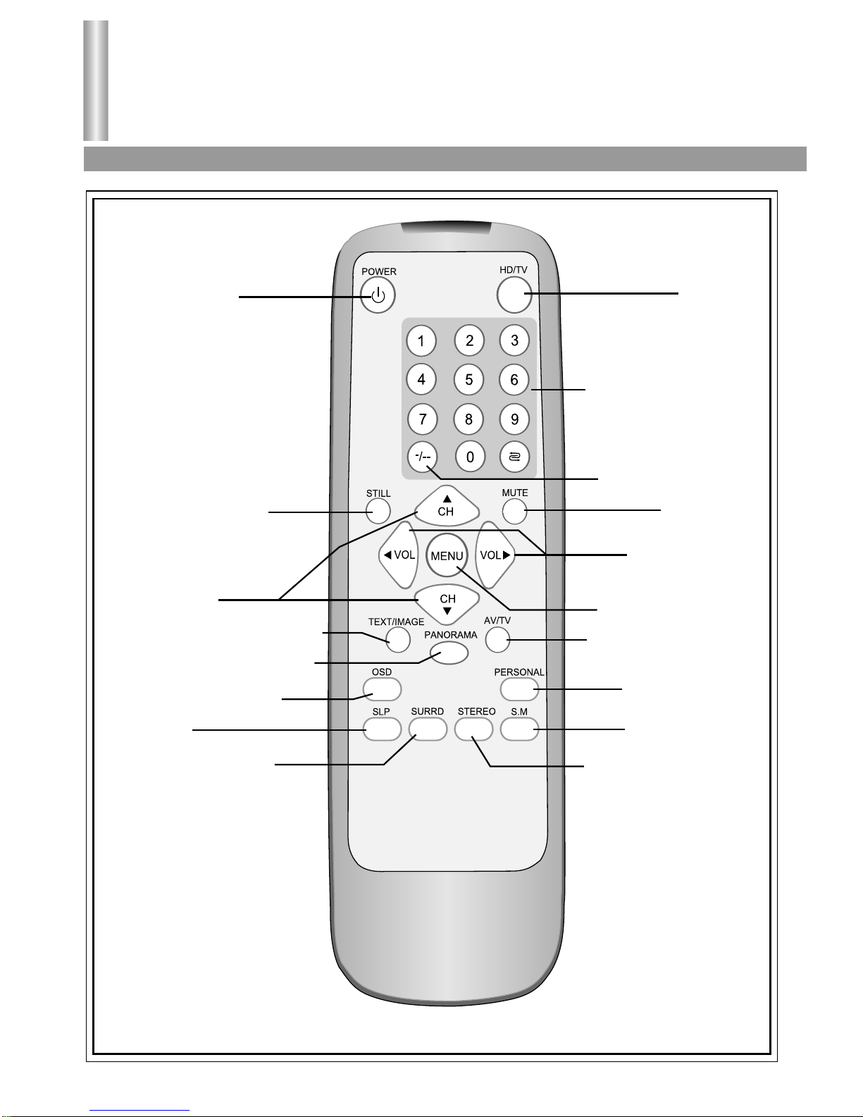
Power on/standby
Still the current picture
Channel up/down
In menu operation used to
move the cursor upward
or downward.
Text /image mode switch over
Screen aspect ratio selection
Retain on-screen display
Sleep timer
Surround sound control
Direct channel selector
Previous channel
One digit/two digit/three
digit channel selector
Sound mute
Volume up/down
Menu item adjust
Selectable picture
Selectable sound
STEREO/ FM Mono selection
6
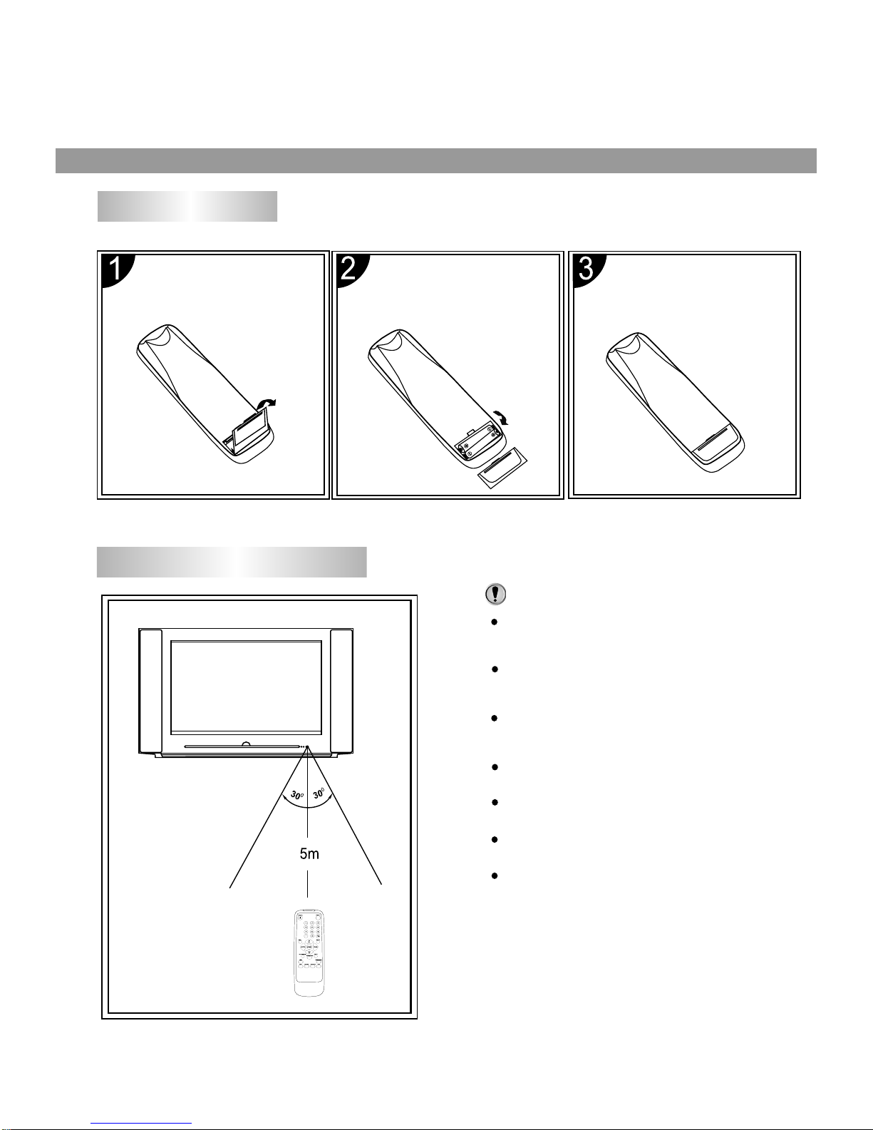
Battery installation
Open the battery
compartment
cover.
Install two "AAA"
batteries, paying
attention to the
polarity diagram in
the battery
compartment.
Replace the battery
compartment cover.
Effective range of the Remote
Notes:
The battery life should be about one year under
normal use. Do not try to recharge batteries not
intended to be recharged.
Use only the size and type of batteries
specified. Do not mix different types of batteries
together or old batteries with fresh ones.
When the remote control will not be used for a
long period of time or when the batteries are
worn out, remove the batteries.
Do not throw the batteries into a fire. Dispose of
used batteries in the specified manner.
Do not drop, dampen or disassemble the
remote control.
When there is an obstacle between the TV and
the transmitter, the transmitter may not operate.
When direct sunlight, and incandescent lamp,
fluorescent lamp or any other strong light
shines on the REMOTE SENSOR of the TV,
the remote operation may be unstable.
Note:
Note:
Installation
Antenna connection/External equipment connections
7
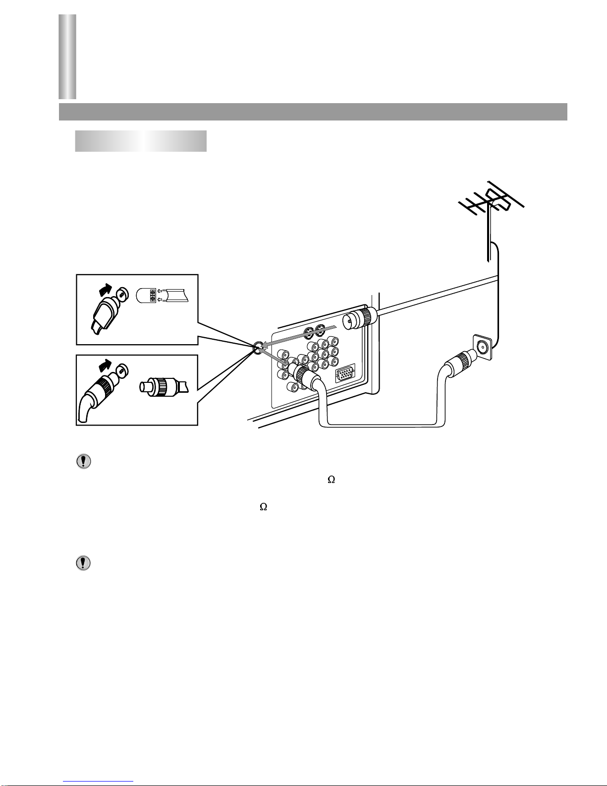
Antenna connection
INSTALL the unit in a room where direct light will not fall upon the screen. Total darkness or a
reflection on the picture screen may cause eyestrain. Soft and indirect lighting is recommended for
comfortable viewing.
To ensure a bright-coloured and clear picture use an outdoor antenna or CATV cable.
In case of using the Twin-lead aerial feeder (300 ) for UHF/VHF aerial, use a 300-75 ohm
adaptor (not supplied)
When using the coaxial cable (75 ) for UHF/VHF aerial, connect the plug into the 75 ohm
aerial socket directly.
1. When you connect the outdoor antenna cable to the antenna terminal on the set, turn off the
power supply to the set first.
2. In thunder and lightning weather, disconnect the outdoor antenna to avoid lightning strike.
3. When receiving CATV programs, a cable box (not supplied) needs to be used.
Video camera, etc.
To video output
To audio outputs
S-VIDEO
VIDEO
L/MONO
R
AV3 IN
THE SET'S REAR
Y
Y
XGA
C
B
P
B
C
R
P
R
S-VIDEO
L/MONO
R
RF IN
AV1
IN
AV2
IN
AV
OUT
HDTV IN
DVD IN
VIDEO
VHSVHS
Y
W
TO ANT IN
To S-VIDEO
output terminal
To video
output
To audio
outputs
To audio
outputs
VTR without
S-VIDEO terminal
VTR with
S-VIDEO terminal
Aerial output
Aerial output
:Yellow (video)
:White (audio L/MONO)
:Red (audio R)
8
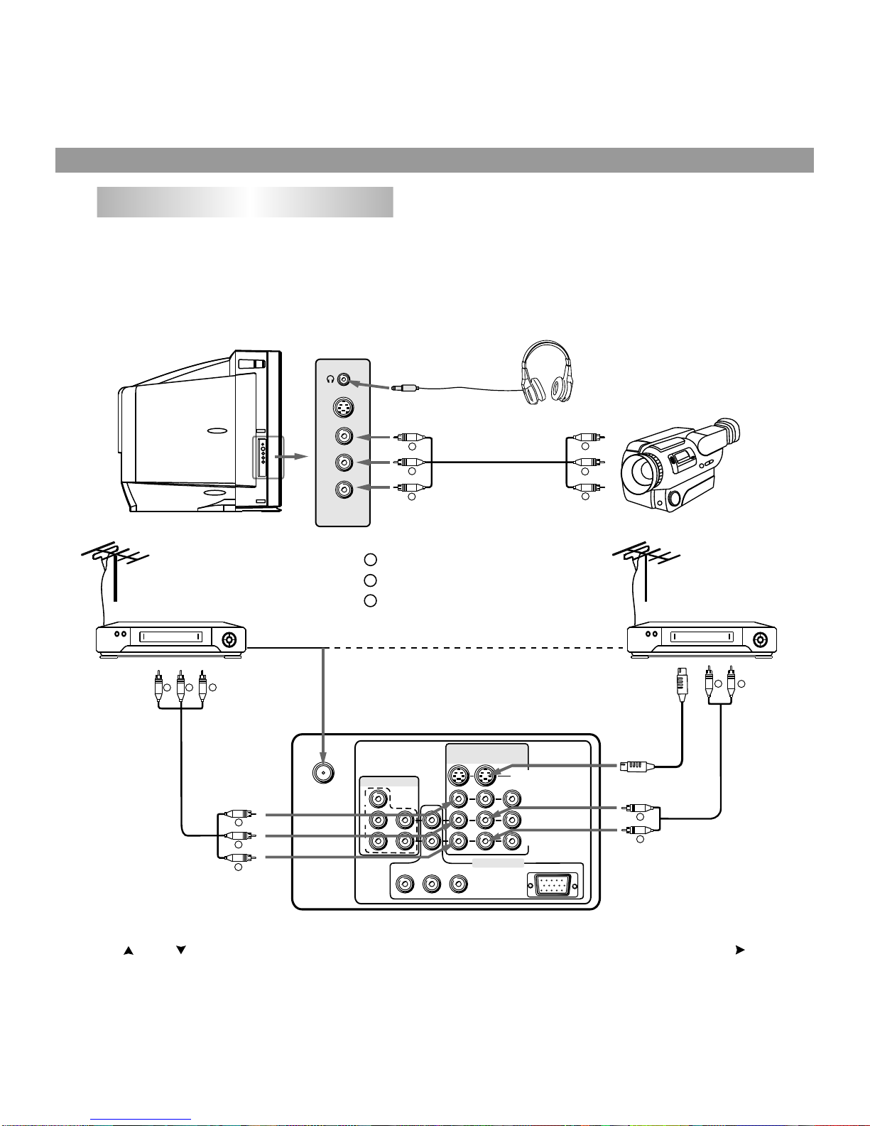
External Equipment Connections
(Please the owner's the refer to manual of
to equipment be connected as well.)
1. To connect AV input terminals
You can connect video equipments such as a VTR and video camera to this TV and enjoy the high
quality picture and sound.
If your video equipment has a S-VIDEO output terminal, connect it to the S-VIDEO input terminal
(special S-VIDEO type) of the unit. If not, connect it to the VIDEO terminal (phono type).
To select the input, press AV/TV button to display the signal source selection menu and press the
CH or CH button to select the corresponding input mode (AV1 or AV2 or AV3) and press VOL
button to confirm.
Note on the S-VIDEO terminal
The S-VIDEO input terminal has priority over the AV1, AV2 VIDEO terminals on the rear and the AV3
VIDEO terminal on the side. To use equipment connected to the video terminals, disconnect any plug
from the S-VIDEO terminal.
R
W
R
Y
W
R
W
R
Y
W
R
Y
W
R
Y
W
R
Installation (continued)
External equipment connections (continued)
9
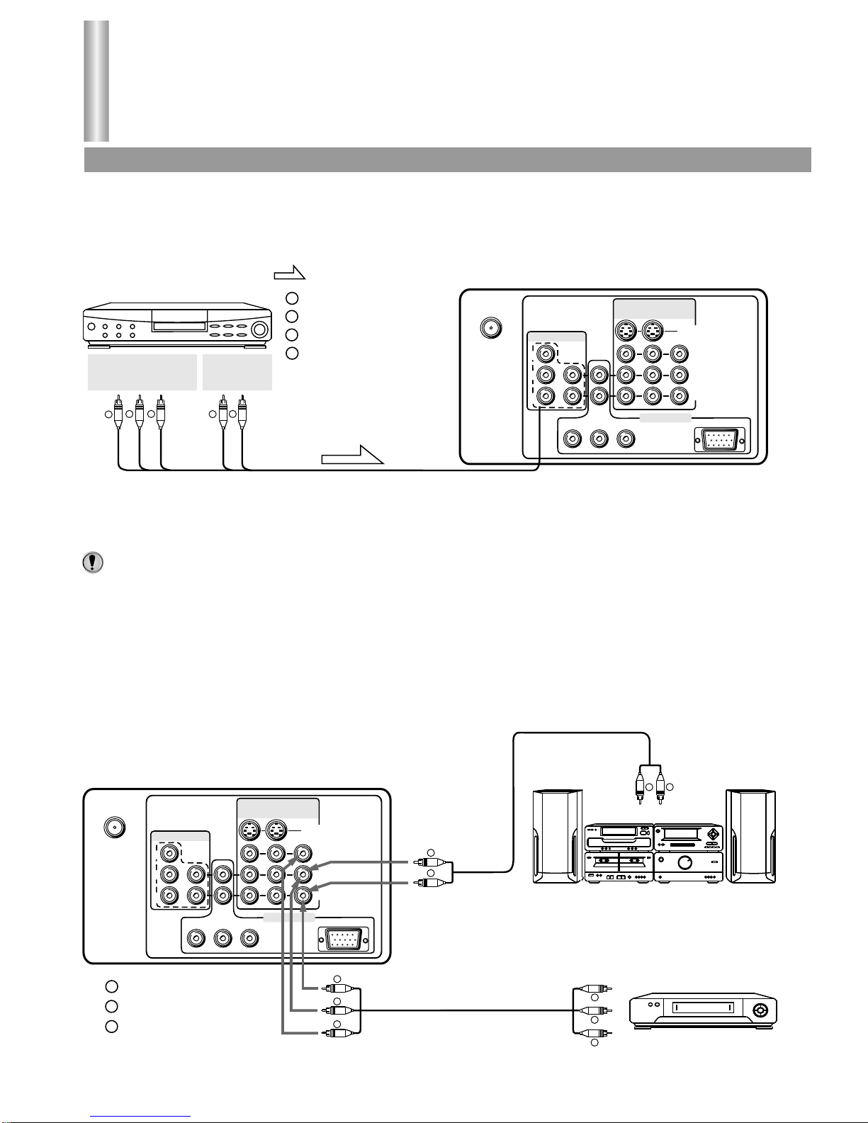
2. To connect DVD input terminals
The figure below shows how to connect the DVD input terminals of the TV set to the DVD Player,
Laser Disk Player, etc.
Press AV/TV button to display the signal source selection menu and select YCbCr mode. The
picture shown on the screen is the program from the DVD Player.
Both the component video Cr terminal and the audio R terminal are red for easy
identification. Make sure these are correctly connected.
3. To connect AV output terminals
You can connect a stereo system to the audio output terminals (phono type) on the set to enjoy a
high-quality sound from the stereo system. You can also connect AV output terminals to VTR to
record programs being displayed on the screen (Note: Only when the signal source is input
through RF or AV1 IN or AV2 IN or AV3 IN, there is signal for AV OUT terminals to output).
Note:
Y
Y
XGA
C
B
P
B
C
R
P
R
S-VIDEO
L/MONO
R
RF
AV1
IN
AV2
IN
AV
OUT
HDTV IN
DVD IN
VIDEO
Y
L/MONO
R
C
B
C
R
THE SET'S REAR
Signals
DVD Player,
Laser Disk Player etc.
:White (audio L/MONO)
:Red (audio R, CR)
:Green (Y)
:Blue (CB)
:Direction of the signal
COMPONENT
VIDEO OUTPUT
AUDIO
OUTPUT
B
W
RR
G
G
W
R
B
Y
Y
XGA
C
B
P
B
C
R
P
R
S-VIDEO
L/MONO
R
RF
AV1
IN
AV2
IN
AV
OUT
HDTV IN
DVD IN
VIDEO
VHS
THE SET'S REAR
To external input
Stereo System
To video input
To audio input
(Another VTR for recording)
:Yellow (video)
:White (audio L/MONO)
:Red (audio R)
Y
W
R
Y
W
R
W
R
Y
W
R
W
R

:White (audio L/MONO)
:Red (audio R, PR)
:Green (Y)
:Blue (PB)
G
W
R
B
10
4. To connect XGA input interface
The figure below shows how to connect the set to the computer through XGA interface.
Press AV/TV button to display the signal source selection menu and select XGA mode. At this time the
screen will display information from the computer.
5. To connect HDTV set top box
If your HDTV set top box is incorporated with YPbPr terminals, connect the set top box to the
TV set through the YPbPr terminals, connect audio lines from set top box to HDTV IN L/R
sound inputs, note that L to Land R to R.
(If your set top box is incorporated with XGA interface, please connect according to "To
connect XGA input interface" which is shown above).
Press AV/TV button to display the signal source selection menu and then select YPbPr mode.
Now you can view programs play backed by the set top box.
Y
Y
XGA
C
B
P
B
C
R
P
R
S-VIDEO
L/MONO
R
RF
AV1
IN
AV2
IN
AV
OUT
HDTV IN
DVD IN
VIDEO
Signals
:White (audio L/MONO)
:Red (audio R)
:Direction of the signal
THE SET'S REAR
COMPUTER
W
R
W
R
W
R
Y
Y
XGA
C
B
P
B
C
R
P
R
S-VIDEO
L/MONO
R
RF
AV1
IN
AV2
IN
AV
OUT
HDTV IN
DVD IN
VIDEO
Y
Y
L/MONO
L/MONO
R
R
P
B
P
B
P
R
P
R
HDTV set top box
:Direction of the signal
Signals
THE SET'S REAR
B
W
R
G
R
B
W
R
G
R
 Loading...