

Page 1

High Definition Digital Receiver
HDSTB200
PALSONIC CORPORATION PTY LTD
1 JOYNTON AVENUE
WATERLOO NSW 2017 AUSTRALIA
TEL: (02) 9313 7111
FAX: (02) 9313 7555
www.palsonic.com.au
PALSONIC CUSTOMER SERVICE
TELEPHONE
AUSTRALIA: 1300 657 888
User Manual
Page 2
Safety Information
RISK OF ELECTRIC SHOCK
CAUTION: TO AVOID THE RISK OF ELECTRIC SHOCK,
NO USER-SERVICEABLE PARTS INSIDE.
REFER SERVICING TO QUALIFIED SERVICE PERSONNEL ONLY.
The lightning flash with arrowhead symbol within an equilateral triangle,
is intended to alert the user to the presence of uninsulated dangerous
voltage" within the product's enclosure that may be of sufficient
magnitude to constitute a risk of electric shock.
The exclamation point within an equilateral triangle is intended to alert
the user to the presence of important operating and servicing instructions
In the literature accompanying the appliance.
CAUTION
DO NOT OPEN
DO NOT OPEN.
WARNING: TO REDUCE THE RISK OF FIRE OR ELECTRIC SHOCK, DO NOT
CAUTION: TO PREVENT ELECTRIC SHOCK. ENSURE 240V AC POWER
CAUTION: CHANGES OR MODIFICATIONS NOT EXPRESSLY APPROVED BY
WARNING:
EXPOSE THIS APPLIANCE TO WATER OR MOISTURE.
PLUG IN FULLY INSERTED INTO THE POWER SOCKET.
THE MANUFACTURER WILL VOID THE USER'S WARRANTY.
TO ENSURE RELIABLE OPERATION AND PREVENT THE HS-STB
FROM OVER HEATING, YOU MUST REMOVE THE PROTECTIVE
PLASTIC FILM FROM THE HS-STB COVER.
Page 3

Important Safeguards
These important safeguard messages will help ensure your enjoyment and proper
use of the HD-STB and accessories. Please read them carefully before you begin
to operate your HD-STB product.
1. Read and Retain this User's Guide
This User's Guide should be read before the HD-STB is operated and retained for
future reference
2. Use Correct Power
This HD-STB should be operated only from the type of power source indicated on
the rear panel.
3. HD-STB Installation
Do not place HD-STB on an unstable trolley stand, tripod, bracket, or table as it
may fall, causing serious injury to a child or adult and damage the HD STB.
4. Provide Antenna Ground
If an outside antenna or cable system is connected to the HD-STB, be sure the
antenna or cable system is grounded to provide some protection against
voltage surges and built-up static charges. An outside antenna system should not
be located in the vicinity or overhead power lines, or other power circuits, where
it can fall onto such power lines or circuits. When installing an outside antenna
system, extreme care should be taken to keep from touching or approaching such
power lines or circuits as contact with them might be fatal. Installing an outdoor
antenna can be hazardous and should be left to a professional antenna installer.
5. Provide Proper Ventilation
Opening slots in the STB cabinet are provided for ventilation to ensure reliable
STB operation and to protect it from overheating. HD-STB should not be located
in an enclosed / built-in installation such as a bookcase unless proper ventilation
is provided.
For sufficient ventilation, there must be at least 10cm free air space above,
behind, top and on each side of the HD-STB.
6. Keep Away from Heat
Do not expose the HD-STB to direct sunlight. This product should be situated
away from heat sources such as radiators, heat registers, stoves and other
electronic products (including amplifiers) that produce heat.
Page 4

Important Safeguard
7. Keep Away from Moisture
Do not use HD-STB near water or in wet areas such as near a bathtub, wash bowl,
kitchen sink, laundry tub, in a wet basement, or near a swimming pool and the
like.
Caution: Maintain electrical safety, Power line operated equipment or
accessories connected to this unit should bear the CE listing mark or C-Tick
certification mark on the accessory itself and should not be modified to defeat
the safety features. This will help avoid any potential hazard from electrical
shock or fire.
8. Do Not Open
Do not attempt to service this HD-STB, as opening or removing STB cover will
expose you to dangerous voltages. To prevent of the risk of fire or electric shock,
do not open the cabinet. There are no user serviceable parts inside the HD-STB.
Refer servicing to qualified service personnel only.
9. Unplug before Cleaning
When cleaning the HD-STB, turn the HD-STB power off and unplug it from the
wall AC outlet before cleaning. Do not use liquid cleaners or aerosol cleaners.
Use a damp cloth for cleaning only.
10. Object and Liquid Entry
Never push objects of any kind through HD-STB openings as they may touch
dangerous voltage points or short-out parts that could result in a fire or electric
shock.
Never spill liquid of any kind on the HD-STB. In case of liquid spillage,
please contact your qualified service centre.
11. For Additional Protection
For added protection during a lightning storm, or when left unattended for long
periods of time, unplug the HD-STB from the AC wall outlet and disconnect the
antenna and A/V cable system. This will prevent damage to the HD-STB from
Lightning and power line surges.
Page 5

CONTENTS
1. Overview of the Equipment
Front Panel - - - - - - - - - - - - - - - - - - - - - - - - - - - - - - - - - - - - - - - - - - - - - - - - - - - Rear Panel - - - - - - - - - - - - - - - - - - - - - - - - - - - - - - - - - - - - - - - - - - - - - - - - - - - Remote Control - - - - - - - - - - - - - - - - - - - - - - - - - - - - - - - - - - - - - - - - - - - - - - - - Installing remote control batteries
Remote Control Universal Code Setting
Accessories
- - - - - - - - - - - - - - - - - - - - - - - - - - - - - - - - - - - - - - - - - - - - - - - - - - -
- - - - - - - - - - - - - - - - - - - - - - - - -
- - - - - - - - - - - - - - - - - - - - - - - - - - - - - - - - - - - -
- - - - - - - - - - - - - - - - - - - - - - - - - - - - - - - -
2. Connecting Your HD-STB - - - - - - - - - - - - - - - - - - - - - - - - - - -
1)
Antenna Connection
HD-STB, TV and VCR antenna connection
HD-STB and TV antenna connection
2)
Video Connection - - - - - - - - - - - - - - - - - - - - - - - - - - - - - - - - - - - - - - - - - - - - - - -
HDMI (High Definition Multimedia Interface) connection
Connecting to a HDTV with HD YPbPr
Connecting to a Conventional TV with S-Video
Connecting to a Conventional TV with Composite Video
3)
Audio Connection
Stereo Audio Connection
Digital Audio Connection
4)
Display Mode Change - - - - - - - - - - - - - - - - - - - - - - - - - - - - - - - - - - - - - - - - - - - -
STB Connection to 576p/720p/1080i High Definition Display
STB Connection to Standard Definition Display
- - - - - - - - - - - - - - - - - - - - - - - - - - - - - - - - - - - - - - - - - - - - -
- - - - - - - - - - - - - - - - - - - - - - - - - - - - - - - - - - - - - - - - - - - - - - -
3. Getting Started - - - - - - - - - - - - - - - - - - - - - - - - - - - - - - - - - - -
Step 1. Unpacking and accessories.
Step 2. Remove Protective Plastic Film.
Step 3. Connect ANT Cable.
Step 4. Connecting the Video.
Step 5. Connecting the Audio.
Step 6. Connecting the Power.
Step 7. Display Mode Setup.
Step 8. Install Remote Control battery and Universal
Code Setting.
Step 9. Check up the On Screen Display.
Step 10. Automatic Channel Search and Channel Change.
3
3
4
5
8
8
10
11
11
12
15
16
17
4. Using Menu System - - - - - - - - - - - - - - - - - - - - - - - - - - - - - - -
1)
User Preference - - - - - - - - - - - - - - - - - - - - - - - - - - - - - - - - - - - - - - - - - - - - - - -
Preferred Audio Type (I-II)
SD Output Aspect Ratio
i-Plate Banner Duration
Front Panel LED Dimmer
Power Restore
1
19
19
Page 6

Channel Setup - - - - - - - - - - - - - - - - - - - - - - - - - - - - - - - - - - - - - - - - - - - - - - - - - -
2)
Channel Favourites
Automatic Channel Scan
Manual Channel Scan
Test Reception
Access & Timer Setup - - - - - - - - - - - - - - - - - - - - - - - - - - - - - - - - - - - - - - - - - - - -
3)
Program Blocking Level
Wake-up Channel
Wake-up Timer
Power-off Timer
Content
2 1
24
System Setup
4)
Time Zone
Auto Power Off
Factory Reset
System Information
TV Remote Control Code List
- - - - - - - - - - - - - - - - - - - - - - - - - - - - - - - - - - - - - - - - - - - - - - - - - -
5. Remote Control Buttons
1) Using INFO button - - - - - - - - - - - - - - - - - - - - - - - - - - - - - - - - - - - - - - - - - - - - - - - -
2) Using EPG button
3) Using LIST & FAV button - - - - - - - - - - - - - - - - - - - - - - - - - - - - - - - - - - - - - - - - - - -
4) Using ZOOM button - - - - - - - - - - - - - - - - - - - - - - - - - - - - - - - - - - - - - - - - - - - - - - -
5) Using FREEZE button
- - - - - - - - - - - - - - - - - - - - - - - - - - - - - - - - - - - - - - - - - - - - - - - -
- - - - - - - - - - - - - - - - - - - - - - - - - - - - - - - - - - - - - - - - - - - - -
6. Trouble Shooting Guide - - - - - - - - - - - - - - - - - - - - - - - - - -
7. Reception Trouble Shooting Guide - - - - - - - - - - - - - - - - - -
8. Specifications - - - - - - - - - - - - - - - - - - - - - - - - - - - - - - - - - -
9. Remote Control Universal Code List - - - - - - - - - - - - - - - - -
26
28
28
29
30
30
30
31
32
34
36
2
Page 7
Overview of the equipment
This section summarises HD-STB buttons, controls, and terminals.
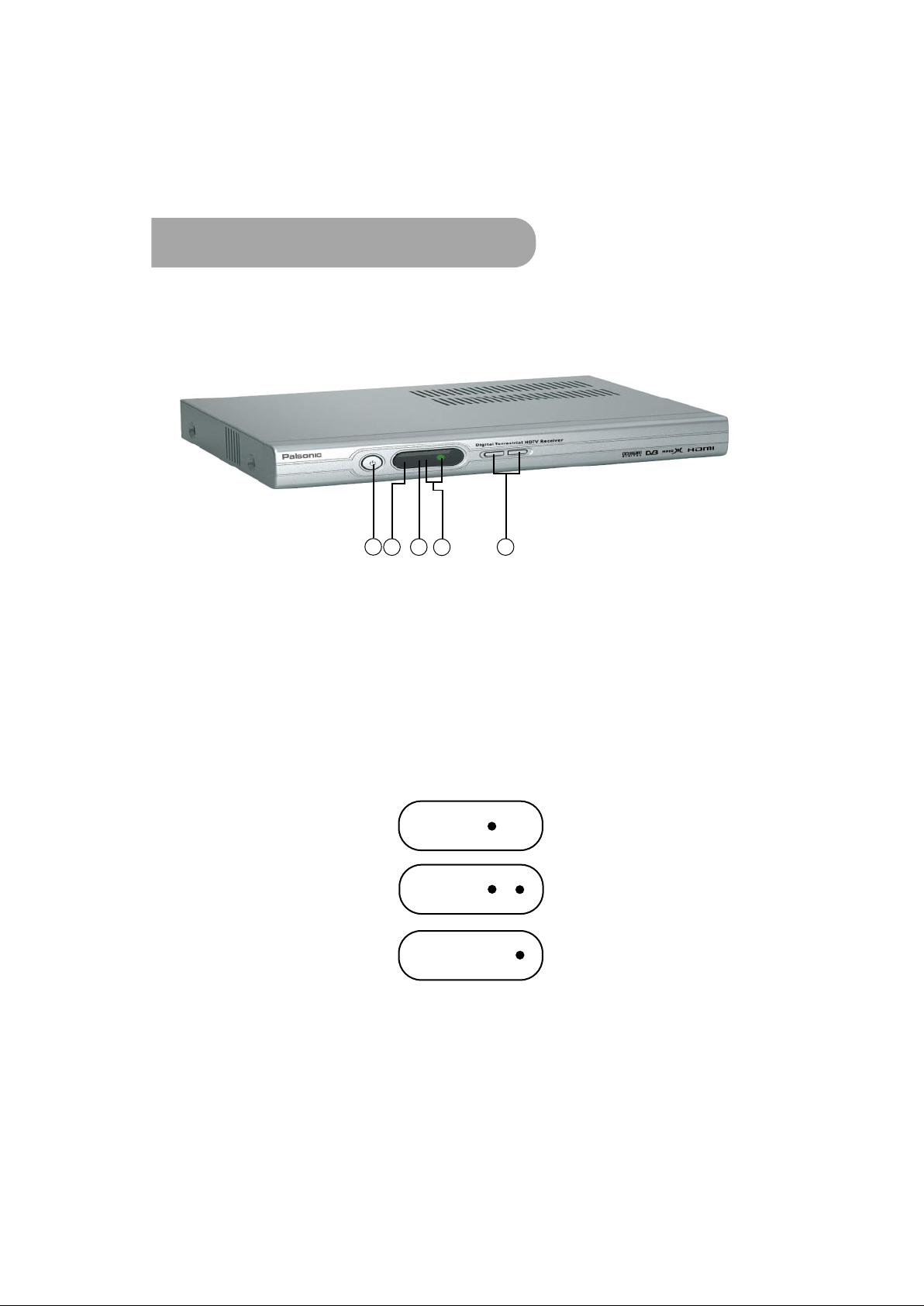
Front Panel
1
3
2
1.
POWER
Press to turn the HD-STB on or off.
2.
Power Indicator
Displays STB operation status. In power off mode, STB will display a RED light. In
power on mode the RED light will flash to acknowledge a remote control key press.
3.
Remote Sensor
Infrared red remote control sensor. To ensure reliable remote control operation do not
place any objects in front of the sensor.
4.
Video Display Mode Indicators
Two green LEDs indicate the current HD video display mode setting LED combination
is as follows:
4
5
576p
720p
1080i
UP / DOWN
5.
Channel up or down movement. These two buttons also change the HD video display
mode as detailed on page 16.
3
Page 8
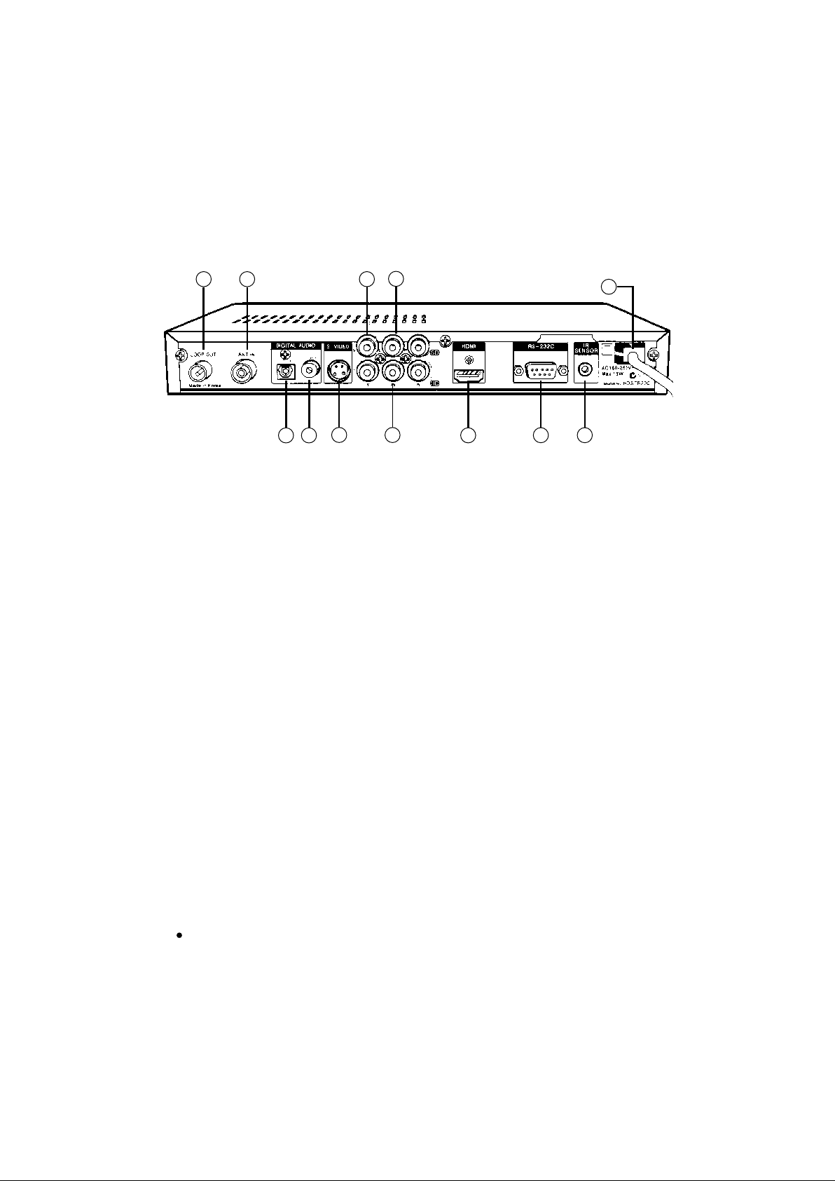
Rear Panel
Overview of the equipment
1
2
1.
LOOP OUT Terminal
3 4
5
7
6
8
9
10
11
Use this terminal to feed RF signal to your TV or VCR for analogue TV reception.
2.
ANT IN Terminal
Attach an external Antenna to this terminal.
3.
Optical Digital Audio (SPDIF) Output terminal
Use this terminal with A/V device equipped with Optical Digital input for Dolby* Digital
5.1-channel sound.
4.
Coaxial Digital Audio (SPDIF) Output terminal
Use this terminal with A/V device equipped with Coaxial Digital input for Dolby* Digital
5.1-channel sound.
5.
S-Video Output terminal
Use this terminal with your TV S-Video input.
6.
TV Composite Video Output terminal (CVBS)
Use this terminal with your TV Video input.
7.
AUDIO L/R (Analog Stereo Audio) Output terminal
This terminal can be used with your TV analog audio input. Refer to Audio Connection.
Pages.
8.
HD YPbPr (HD Component Video) Output terminal.
Use this terminal with your TV HD Component Video input. (HDTV only)
9.
HDMI Output terminal
Use this terminal with your TV HDMI Video input.
10.
RS-232C
Use this terminal for software upgrade purpose only.
11.
External IR Sensor Terminal
Use this terminal for External IR Sensor connection.
12.
Power Cord
Plug this Cord to the specified AC Power socket.
12
Manufactured under license from Dolby Laboratories. Dolby and the double-D Symbol are
trademarks of Dolby Laboratories.
4
Page 9
Overview of the equipment
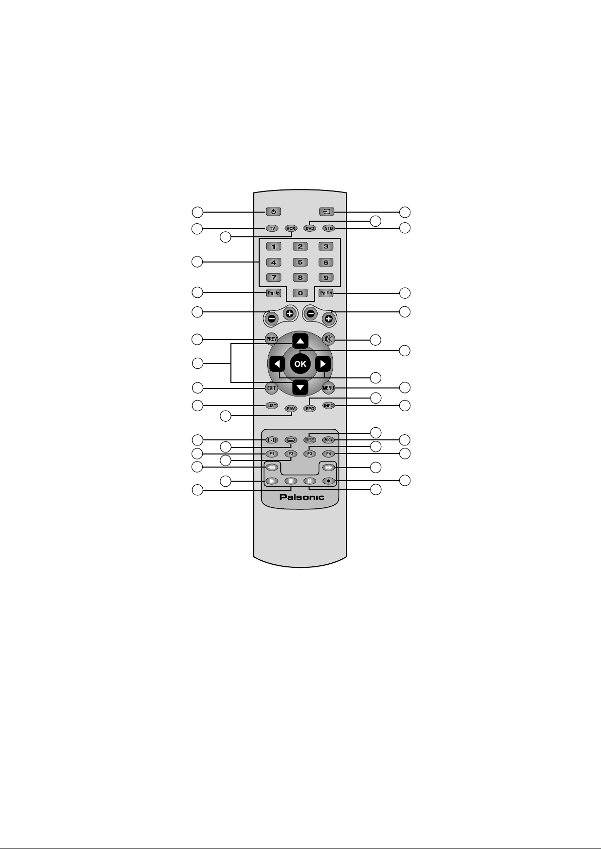
Remote Control
1
2
3
4
5
6
7
8
9
10
11
12
13
14
15
16
17
18
19
20
21
22
23
24
25
26
27
28
29
30
31
32
33
34
35
36
POWER
1.
Turn your HD-STB on or off.
TV
2.
Change your Remote Controller to TV mode.
VCR
3.
Change your Remote Controller to VCR mode.
0~9 (Number Button)
4.
Direct change the desired channel.
To change the channel, simply press desired channel number.
The button operation should be less than 2 seconds between button pressing.
5
Page 10

Overview of the equipment
5.
PgUp (STB Mode)
In the menu system, move up item list by page.
6.
CH+ / CH-
Change the TV/HDTV's analog channel / Change the STB's digital channel.
7.
PREV (Previous Channel - STB mode)
Go to the previous watched channel.
8.
Up / Down
In the menu system, move up or down the cursor.
9.
Exit
In the menu system, exit menu from any menu level.
10.
LIST (STB Mode)
Set & display ALL DTV channel list as the default channel list.
11.
FAV (STB Mode)
Set & Display FAV DTV channel list as the default favourite channel list.
12.
I-II (STB mode)
Switch between MPEG and Dolby Digital audio.
13.
Subtitle (STB Mode)
Enable/ disable program subtitles.
14.
RED (F1)
RED button. Also worked with function 1 button.
15.
GREEN (F2)
GREEN button. Also worked with function 2 button.
16.
REWIND
In the VCR or DVD mode, it works with REWIND button.
17.
PLAY
In the VCR or DVD mode, it works with PLAY button.
18.
STOP
In the VCR or DVD mode, it works with STOP button.
19.
AV (TV's External Video Input Selection)
Select the TV External Video Input.
20.
DVD
Change your Remote Controller to DVD mode.
21.
STB
Change your Remote Controller to STB mode.
22.
PgDn (STB Mode)
In the menu system, move down item list by page.
23.
VOL+ / VOL-
Change the TV/HDTV's volume level up or down.
6
Page 11

Overview of the equipment
24.
MUTE
Activate TV/HDTV's mute operation.
25.
OK (STB Mode)
Confirm current menu item selection.
26.
Left / Right
In the menu system, move the cursor left or right.
27.
MENU (STB Mode)
Enter STB menu. Whilst in the STB menu, this key also functions as the BACK key.
28.
EPG (Electronic Program Guide STB mode)
Activate Electronic Program Guide information broadcast by the DTV networks.
29.
INFO (STB Mode)
Display current channel information. You can see the information of current channel.
30.
FREEZE (STB mode)
Freeze the current picture while audio continues normally in the background.
31.
ZOOM (STB Mode)
Zoom out 4:3 pillar box black bars. (Available on HD YpbPr and HDMI only).
32.
YELLOW (F3)
YELLOW button. Also works with function 3 button.
33.
BLUE (F4)
BLUE button. Also works with function 4 button.
34.
WIND
In the VCR or DVD mode, it works with WIND button.
35.
PAUSE
In the VCR or DVD mode, works with PAUSE button.
36.
REC
In the VCR or DVD mode, it works with REC button.
7
Page 12
Overview of the equipment
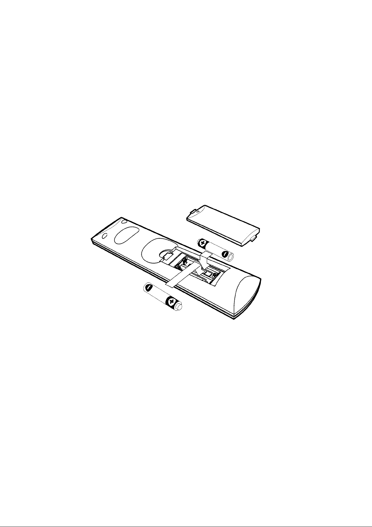
Installing the remote control batteries
Cautions:
Always replace batteries in pairs of the same brand. Do not mix batteries from different
brands or use an old and a new battery.
Replace old or weak batteries to avoid battery leakage which can damage the remote control.
Dispose old batteries thoughtfully with due respect to the environment. Do not incinerate old
batteries.
l) Open the battery compartment on the back of the remote control.
2) Install two AAA (LR03) size batteries as shown.
Make sure the "+" and "-" terminals are oriented correctly.
3) Replace the cover.
4) After changing the batteries, please reset Remote Control Universal Code
Setting.
Remote Control Universal Code Setting
This Remote Control is also compatible with a range of popular CE brands
To use this remote with other CE equipment, you must program the remote with a universal
code number as detailed on page 36.
There are two methods of entering the universal code.
1. Using Automatic Code Search
1) Turn on the CE component (TV, VCR or DVD) you want to control.
2) Press and hold the CE component (TV, VCR or DVD) button until the LED on the
remote control stays on, then release the button.
3) Point the remote at the CE component (TV, VCR or DVD) and press the UP (A) button,
then wait for three seconds or until the LED stops flashing.
At this point the remote control is searching for the correct code. If, after three
8
Page 13

Overview of the equipment
seconds, the CE component (TV, VCR or DVD) does not turn off, press the UP ( )
button again which tells the remote to search the next set of codes.
Continue pressing and releasing UP ( ) button until the CE component (TV, VCR or
DVD) turns off.
4)
If the CE component (TV, VCR or DVD) turns off; press the OK button, and then the
LED blinks three times.
2. Using Direct Entry Method
1) Turn on the CE component (TV, VCR or DVD) you want to control.
2) Refer the brand Code List on page 36 and locate your brand of the component you
want to control.
3) Press and hold the CE component (TV, VCR or DVD) button you want to program until
the LED on the remote control turns on, then release the key.
4) Enter 3-digit code from the code list, then the LED blinks three times.
5) If you get no response, repeat these steps using the next code listed for your brand
until the CE component (TV, VCR or DVD) responds to the remote control command.
3. Using the remote control
1) Ensure there is a direct and unblocked line of sight between the remote control and
the HD-STB.
2) Dark walls, direct sunshine or very bright light may reduce the remote sensor's
sensitivity.
3) The remote control will not work correctly if you press several buttons at the same
time.
4) Hold the remote control within an angle range of about 30 degree from either side of
the remote sensor. The remote control range about 23 feet (7 metres) from the HD STB.
5) Remember to press the mode selection button (ie; TV, VCR or DVD) before pressing a
remote control button to control the device.
9
Page 14

Overview of the equipment
Accessories
Carefully remove the HD-STB from the carton. Check that the HD-STB has not been
Damaged. The following accessories are included.
1. Wireless Universal
Remote Control
4. A/V Cable
SD A/V Cable (Yellow/White/Red)
HD Video Cable (Green/Blue/Red)
7. RF Cable
2. Two AAA (LR03)
size batteries
5. Bracket
3. User Manual
6. External IR Module
10
Page 15

Connecting your HD-STB
1. Antenna Connection
HD-STB, TV and VCR antenna connection
Connect IEC-Male antenna cable into HD-STB 'ANT IN' terminal.
Connect VCR 'ANT IN' cable into HD-STB 'LOOP OUT' terminal.
Connect VCR 'LOOP OUT' cable into TV RF IN terminal. (Refer to Fig. 1)
HD-STB and TV antenna connection
Connect IEC-Male antenna cable into HD-STB 'ANT IN' terminal.
Connect HD-STB 'LOOP OUT' cable into TV RF IN terminal. (Refer to Fig. 2)
Fig. 1 HD-STB, TV and VCR antenna
connection
To ensure optimum DTV reception the HD STB must be the first device connected to the antenna
system when daisy chaining RF input / output products such as VCRs, DVD Recorders and analog
television as illustrated in Fig. 1 and 2.
Fig. 2 HD-STB and TV antenna
connection
11
Page 16

Connecting your HD-STB
2. Video Connection
HDMI (High Definition Multimedia Interface) connection
HDMI is the new digital inter-connection standard that carries digital video & audio
signals via a single cable.
HD-STB HDMI output supports the following 50Hz HD video modes: 1080i, 720p,
and 576p SD via HDMI is not supported.
Connect HDMI cable between HD-STB and TV HDMI terminals as shown
(Refer to Fig. 3)
The HD-STB HDMI connection is also DVI compatible when using a HDMI to DVI
cable (not supplied) or HDMI to DVI gender changer (not supplied) (Refer to Fig. 4)
When using a HDMI to DVI connection, a separate audio connection is also required
between the HD-STB and display device.
12
Fig. 3 HDMI to HDMI Input TV
Fig. 4 HDMI to DVI Input TV
Page 17

Connecting your HD-STB
Connecting to a HDTV with HD YPbPr
Connect YPbPr cable between HD-STB and your TV as shown in Figure 5.
HD-STB YPbPr output supports the following 50Hz HD video modes: 1080i, 720p
and 576p SD via YPbPr is not supported.
1) Connect YPbPr Video cable to the HD terminal on the back of HD-STB
2) Connect the other end of the YPbPr cable to the HD YPbPr input terminal on
the HDTV
3) Usually, the Y is Green colour. Pb is Blue colour, and Pr is Red colour
assigned.
4) Setting Up the Display desired resolution.
Fig. 5 HD YPbPr Video Connection
13
Page 18

Connecting you HD-STB
This HD-STB simultaneous output the HD Video and SD Video. So, you can watch HD Video and
recording SD Video at the same time.
For the SD Video connection, please refer below diagram.
Connecting to a Conventional TV with S-Video
Connect a S-Video cable to the S-Video terminal on the rear of HD-STB. Connect the
other end of S-Video cable to the S-Video input terminal on the TV. (Refer to Fig. 6)
Fig. 6 TV with S-Video Connection
Connecting to a Conventional TV with Composite Video
Connect a Video Cable to the TV Video terminal on the rear of the HD-STB.
Connect the other end of Video Cable to the Video input terminal on the TV.
Fig. 7 TV with Composite Video Connection
(Refer to Fig. 7)
14
Page 19

This HD-STB can support four different options for connecting audio signals. Each of
the audio connections delivers the same audio sound. You can select desired audio
connection by following the Audio connection Diagrams below.
Pease make sure, if you are using HDMI connection, you do not need this Audio
Connection. The HDMI connection is already included Digital Audio internally.
Stereo Audio Connection
Audio L/R deliver analog stereo sound or Dolby Digital 2-channel downmix
analog stereo sounds. Connect Audio Cable to Audio L/R terminal on the rear of the
HD-STB.
Connect the other end of the Audio Cable to the conventional TV Audio input or
Stereo Amplifier Audio Input. (Refer to Fig. 8)
Fig. 8 Stereo Audio Connection
Digital Audio Connection
Optical Digital Audio and Coaxial Digital Audio deliver Dolby Digital 5.1-channel
digital sound or PCM digital sound.
If you have a Home Theatre system and it can receive Digital Audio, then you can
connect Digital Audio.
For the Optical Digital Audio connection, connect the Optical Digital Audio Cable
(Available in Local Store) to the Optical Audio terminal on the rear of the HD-STB.
Connect the other end of the Optical Digital Audio Cable to the Optical Audio input
terminal on the Home Theatre System.
For the Coaxial Digital Audio connection. connect the RCA Cable to the Coaxial
Audio terminal on the rear of the HD-STB. Connect the other end of the RCA Cable
to the Coaxial Audio input terminal on the Home Theatre System. (Refer to Fig. 9)
Fig. 9 Digital Audio Connection
15
Page 20

Connecting your HD-STB
4. Display Mode Change
This HD-STB supports simultaneous video output of HD and SD.
For HD output, it required display mode setting.
This HD-STB supports Native 1080i/50Hz, Native 720p/50Hz and Native 576p/50Hz.
The factory default is Native 1080i/50Hz.
For change the output display mode, please check up your TV support display mode. To
determine which resolution your HD input television supports, please consult the
Television's user manual.
For change display mode, please follow below procedure.
1) Press front panel UP and DOWN button simultaneously.
2) Press front panel UP or DOWN button for desired display mode.
The OSD will show selected mode and LED indicator will blink.
3) Press front panel UP and DOWN button simultaneously again to change
selected Display Mode.
STB Connection to 576p/720p/1080i High Definition Display
Most Plasma and LCD display and some CRT television with HD input(s) fall into this
category. To determine which resolution(s) your display support, consult the user
manual for your display device.
STB Video Output
1080i
720p
576p
Video Output Scan Frequency
28.125 KHz
37.500 KHz
31.250 KHZ
STB Video Connection
HD-YPbPr
HDMI
STB Connection to Standard Definition Display
Most existing 4:3 televisions fall into this Category.
For optimum SD picture quality, we recommend S-Video connection. If your TV sets
dose not supports S-Video then you should use the composite (CVBS) Video input.
(Yellow cinch socket)
STB Video Output Video Output Scan Frequency STB Video Connection
576i 15.625 KHz
S-Video and CVBS
16
Page 21

Getting Started
Step 1. Unpacking and accessories.
After open the gift box, you should check up and find the following items.
- Digital HD-STB
- Universal Remote Control
- 2 Batteries AAA (LR03) size
- User Manual
- SD A/V Cable (Yellow/White/Red) & HD Video Cable (Green/Blue/Red)
- Bracket
- External IR Module
- RF Cable
If you find a missing or broken parts, then ask your supplier or contact the service
centre.
Step 2. Remove protective plastic film.
Remove protective plastic film from HD-STB top cover.
Step 3. Connect ANT Cable.
Connect external ANT cable to ANT IN.
Connect another ANT cable between LOOP OUT of HD-STB and ANT IN of TV for
analog reception.
Step 4. Connecting the Video.
Prepare HD-STB and HDTV you want to connect.
There are several methods to connecting the video. You should find the correct
connection method for your HDTV. Please refer to the Video Connection Diagram.
Step 5. Connecting the Audio.
Prepare HDTV or Audio equipment you want to connect.
If you are using HDMI connection, you do not need audio connection.
There are four different connection methods for Audio connection. For general TV
analog audio connection, it has Audio L/R.
For digital audio connection, you should prepare Optical Audio cable for optical audio
connection with Home Theatre Equipment.
If your Home Theatre Equipment system has coaxial digital input, you can use wellshielded RCA cable for coaxial audio connection.
Step 6. Connecting the Power.
Plug the Power Cord to wall AC outlet. The power source is AC 180-250V, 50/60Hz.
This unit is designed for continuous operation. Switching it off does not disconnect it
from the AC outlet. To disconnect this HD-STB from AC outlet, you have to unplug the
HD-STB.
Step 7. Display Mode Setup.
The default display mode is native 1080i. If you need change the display mode, press
the UP and DOWN button at the front panel simultaneously for display mode change.
Press UP or DOWN button at the front panel to select desired display mode.
Press UP and DOWN button concurrently to confirmed display mode change.
17
Page 22

Getting Started
Step 8. Install Remote Control battery and Universal Code
setting.
Install Remote Control battery. The battery has polarity so when insert the batteries
make sure the "+" and "-" terminals are oriented correctly. The mode selection,
buttons are TV, VCR. DVD and STB. You can change the code of other CE component
with this mode button. For more detailed information, please refer to the Remote
Control Universal Code Setting section.
Step 9. Check up the On Screen Display.
For verify correct setting of Display Mode, you should check up the OSD from HDTV's
display screen.
Turn on the HD-STB and HDTV. Press Menu button on the remote control, you should
check up the OSD for verify A/V connection. If you cannot find any OSD in your TV
display, please check up again the Display Mode Setting and A/V connection.
Step 10. Automatic Channel Search and Channel Change.
Please set the time Zone and perform the Automatic Channel Search to find possible
channels. Please make sure, you should wait until fully searched. Normally, it will take
several minutes.
If you setting up the favourite channel using Favourite Setup in the menu system, you
can change the channel using "CH+" or "CH-" between selected favourite channels.
Please make sure in favourite channel mode, the channel change operation is based on
Favourite Setting in the internal memory. If you unmark the channel in the favourite
list, you cannot access the channel using "CH+ of "CH-" button. At that time, please
perform the Favourite Setup and mark the Channel in the favourite list.
18
Page 23

Using the MENU System
From here you can adjust whole setting and function of HD-STB.
If you press the MENU button, the menu screen will display.
You can move up and down using UP or DOWN button in the menu system. Press OK or RIGHT
button to select the items. MENU button will go back to one step back.
If there is no remote control activity more than 60 sec, then all menu will automatically
disappear for prevent unwanted operation.
1. User Preference
From here you can adjust User Preference settings concerning your TV.
Preferred Audio Type (I-II)
You can select desired audio signal from broadcaster. If you select Dolby Digital
and broadcaster simultaneous broadcast the Dolby Digital and MPEG audio, then
your HD-STB will check up the Dolby Digital audio first and decode Dolby Digital
audio.
If you select Dolby Digital but broadcaster broadcast MPEG audio only, then your
HD-STB will check up the Dolby Digital audio first and next select MPEG audio
automatically.
Also you can set up Audio Preference (I-II) with I-II button on the remote control.
But this change is affected to selected channel only If you change channel or turn
off the HD-STB, then default audio type be selected.
1) Press MENU to display the menu.
2) Press OK or RIGHT to select the User Preference menu.
3) Press RIGHT to select sub-menu.
4) Press UP or DOWN to select desired audio mode.
5) Press OK or RIGHT to save the selected audio mode.
6) Press MENU to exit the menu.
User Preference
Preferred Audio Type
SD Output Aspect Ratio
i-Plate Banner Duration
Front Panel LED Dimmer
Power Restore
Preferred audio type when program contains MPEG and
Dolby Digital audio
MPEG
Dolby Digital
10 sec
High
Disable
19
Page 24

Using the MENU System
SD Output Aspect Ratio
You can select best fitting display mode for your SD TV screen.
This function is available only Composite Video and S-Video output when the 16:9
source is coming from Broadcaster. The 16:9 format is the standard mode for most
wide TV screens. You can select Widescreen or 4:3 Letter Box for fit your SD TV's
screen.
1) Press MENU to display the menu.
2) Press OK or RIGHT to select the User Preference menu.
3) Press DOWN to select display format menu.
4) Press RIGHT to select sub-menu.
5) Press UP or DOWN to select desired display format.
6) Press OK or RIGHT to save the selected display format.
7) Press MENU to exit the menu.
User Preference
Preferred Audio Type
SD Output Aspect Ratio
i-Plate Banner Duration
Front Panel LED Dimmer
Power Restore
Select TV screen aspect ratio type connected to STB
rear panel SD Video / S-Video output terminals.
MPEG
Widescreen
4:3 Letter Box
High
Disable
i-Plate Banner Duration
You can adjust Information Banner (i-Plate) time duration. If you feel i-Plate time is
too long or short, you can select time out period using i-Plate Banner Duration
setup. It is affected with i-Plate and 7-DAY EPG display.
Front Panel LED Dimmer
You can adjust front LED display brightness. If you feel the front panel LED is too
brighter or darker, you can adjust the brightness of LED display using Front Panel
LED Dimmer setup.
Power Restore
This HD STB has Power Restore function If you setup the Power Restore to Enabled
and when AC main power is restored, the HD-STB will automatically turn on and
display final memorised channel. It is useful for multiple display or exhibition for
control the HD-STB. After setup the Power Restore to Enabled, just turn on the AC
main power for HD-STB on and turn off the AC main power for HD-STB off. The
factory default value is Power Restore Disabled.
20
Page 25

Using the MENU System
2. Channel Setup
From here you can adjust Favourite Setup settings or channel search concerning your TV.
After automatic channel scan, you can assign whole scanned channels to TV Favourite
List or Radio Favourite List.
You can change channel list mode by pressing LIST button or FAV button.
Channel Favourites
You can assign any scanned channel to TV Favourite List / Radio Favourite List. After
assigned each channel to Favourite List, then it will appear in FAV Channel list.
Here is the TV Favourite List setup procedure.
1) Press MENU to display the menu.
2) Press DOWN to select the Channel Setup menu.
3) Press OK or RIGHT to enter Channel Setup menu.
4) Press OK or RIGHT to enter Channel Favourites menu.
5) Press OK or RIGHT to enter to TV Favourite edit display.
6) If you want add or exclude individual channel, press RIGHT or OK to
select to individual channel list.
7) In this sub menu, press INFO button for display selected channel signal
status. For quit signal status, press INFO button again. It is useful for
duplicate channel presence.
8) Press Menu to go back.
Channel Setup > Channel Favourites
TV Favourite
Radio Favourite
7 7 Digital
70 7 HD Digital
71 7 Digital 1
72 7 Digital 2
73 7 Digital 3
77 7 Guide
Press OK to select / deselect favourite channel.
Press Pg Up/Dn to move between pages.
To check channel signal quality, press info.
21
Page 26

Using the MENU System
Automatic Channel Scan
From here, the HD-STB will perform automatic scan the whole channel frequency for
available digital channels. It will take several minutes. In the process of Automatic
Channel Scan, the searched channel will memorise to the internal memory. After
that, you can assign these channels to Favourite Channel List.
1) Press MENU to display the menu.
2) Press DOWN to select the Channel Setup menu.
3) Press OK or RIGHT to enter Channel Setup menu.
4) Press DOWN to select Automatic Channel Scan.
5) Press OK or RIGHT to go to Sub menu.
6) Press OK to Start Automatic Scan procedure.
7) The Automatic Scan procedure will take several minutes.
8) After finished the Automatic Scan procedure, the searched program will
automatic memorise in the internal memory.
9) The menu will be exited automatically.
Channel Setup > Automatic Channel Scan
Physical Channel
Logical Channel Found
Channel scan in progress, please wait...
UHF 39 606.5.5MHz
6
40%
Manual Channel Scan
You can manually find the program in one of the specific channels. When you
perform Manual Channel Scan you need to select the local broadcaster digital
channel number. In this process, the HD-STB will try to find available digital
program in the selected channel number. After finished Manual Channel Scan, the
HD-STB will memorise to the internal memory.
1) Press MENU to display the menu.
2) Press DOWN to select the Channel Setup menu.
3) Press OK or RIGHT to enter Channel Setup menu.
4) Press DOWN to select manual Channel Scan.
5) Press OK or RIGHT to go to Sub menu.
6) For select Physical Channel. Press RIGHT or OK to display physical
channel table.
7) Press UP/DOWN or PgUp/PgDn to select physical channel number.
8) Press OK or RIGHT to select the channel you want to manual scan.
9) Press LEFT to return.
10) Press DOWN to select Start Manual Scan.
11) Press OK to Start Manual Scan. Also the progress bar will display
scanning progress.
12) After finished the Manual Channel Scan, the searched program will
automatically memorised to the internal memory. Press MENU to go
back.
22
Page 27

Using the MENU System
Channel Setup > Automatic Channel Scan
Physical Channel
Start Manual Scan
Services Found 6
UHF 34 571.5MHz
40%
Test Reception
You can review your aerial signal strength using this menu.
In this menu, you can check up the Network Name, COFDM Parameters, Signal
Strength and Signal Quality.
1) Press MENU to display the menu.
2) Press DOWN to select the Channel Setup menu.
3) Press OK or RIGHT to enter Channel Setup menu.
4) Press DOWN to select Test Reception.
5) Press OK or RIGHT to go to Sub menu.
6) For change physical channel, Press OK or RIGHT again to display
physical channel list.
7) Press UP/DOWN or PgUp/PgDn to select the physical channel you want
to check up the signal strength.
8) Press OK or RIGHT to change physical channel.
9) Press LEFT to return. You can check up and review the signal strength,
quality and signal related information.
10) Press MENU to go back.
Channel Setup > Test Reception
Physical Channel
Network Name
COFDM Parameters
Signal Strength
Signal Quality
Seven Network
8K 64QMA 7/8FFC 1/32GI
UHF 34 571.5MHz
23
Page 28

3. Access & Timer Setup
Program Blocking Level
You can setup channel blocking level with this item. If current channel having a
lower level than Program Blocking Level which you setting up previously then the
display will be blanked and shows blocked message with OSD. Whenever you enter
Program Blocking Level menu. HD-STB always asking you PIN code.
1) Press MENU to display the menu.
2) Press DOWN to select the Access & Timer Setup menu.
3) Press OK or RIGHT to select Access & Timer Setup menu.
4) Press OK or RIGHT to go to Sub menu.
5) HD-STB will ask you enter the PIN code.
6) Press UP or DOWN to select the Program Blocking Level you want to setup.
7) Press OK or RIGHT to change Program Blocking Level.
8) Press MENU to go back.
Access & Timer Setup
Program Blocking Level
Wake-up Channel
Wake-up Timer
Power off Timer
When enabled, programs above the selected
parental guidance rating will not be shown.
Current Time 8:34 pm
Disable
R and above
AV and above
MA and above
M and above
PG and above
G and above
Wake-up Channel
You can select any channel when Wake-up Timer is turned on the HD-STB. The
default is last watched channel. For select the desired channel, you should setting
up the Wake-up Channel.
1) Press MENU to display the menu.
2) Press DOWN to select the Access & Timer Setup menu.
3) Press OK or RIGHT to select Access & Timer Setup menu.
4) Press DOWN to select Wake-up Channel menu.
5) Press OK or RIGHT to go to Sub menu.
6) Press UP or DOWN to select desired channel you want to setup.
7) Press OK or RIGHT to change desired channel.
8) Press MENU to go back.
Access & Timer Setup
Program Blocking Level
Wake-up Channel
Wake-up Timer
Power off Timer
Current Time 8:35 pm
M and above
Last channel
7 7 Digital
70 7 HD Digital
71 7 Digital 1
72 7 Digital 2
73 7 Digital 3
77 7 Guide
24
Page 29

Using the MENU System
Wake-up Timer
You can setup the Wake-up Timer for automatic turn on the HD-STB.
When the setting up time is reached, the HD-STB will automatic turn on and display
setting up channel. This Wake-up Timer is operating daily. You can refer current
time upper side right of the OSD.
1) Press MENU to display the menu.
2) Press DOWN to select the Access &Timer Setup menu.
3) Press OK or RIGHT to select Access & Timer Setup menu.
4) Press DOWN to select Wake-up Timer menu.
5) Press OK or RIGHT to go to Sub menu.
6) Press UP or DOWN button enabling sub menu.
7) Use UP/DOWN or numeric button to change time.
8) Press LEFT or RIGHT to move each item.
9) After finished setup, press MENU or LEFT to go back.
Access & Timer Setup
Program Blocking Level
Wake-up Channel
Wake-up Timer
Power off Timer
When enabled, STB will automatically turn on
every day at the selected time.
Power-off Timer
You can setup the Power off Timer for automatic turn off the HD-STB.
When the setting up time is reached, the HD-STB will automatically turn off. This Poweroff Timer is operating daily.
1) Press MENU to display the menu.
2) Press DOWN to select the Access &Timer Setup menu.
3) Press OK or RIGHT to select Access &Timer Setup menu.
4) Press DOWN to select Power-off Timer menu.
5) Press OK or RIGHT to go to Sub menu.
6) Press UP or DOWN button enabling sub menu.
7) Use UP/DOWN or numeric button to change time.
8) Press LEFT or RIGHT to move each item.
9) After finished setup, press MENU or LEFT to go back.
Access & Timer Setup
Program Blocking Level
Wake-up Channel
Wake-up Timer
Power off Timer
Current Time 8:35 pm
M and above
Last channel
11 : 12 AM
- - : - - AM
Current Time 8:36 pm
M and above
Last channel
11 : 12 AM
12 : 50 PM
When enabled, STB will automatically turn off
every day at the selected time.
25
Page 30

Using the MENU System
4. System Setup
From here you can setup Time Zone, Auto power off, Factory Reset and check up the HDSTB's system information.
Time Zone
From here you can setup the Time Zone. You should select the time zone information
after factory Reset. It is for correct time display when EPG information is displayed.
1) Press MENU to display the menu.
2) Press DOWN to select the System Setup menu.
3) Press OK or RIGHT to select System Setup menu.
4) Press OK or RIGHT to enter sub menu.
5) Press UP or DOWN to select Time Zone.
6) Press OK or RIGHT to change Time Zone where you live.
7) Press MENU to go back.
System Setup
Time Zone
Auto Power Off
Factory Reset
System Information
TV Remote Control Code List
Select your time zone.
NSW/ACT
VIC
QLD
SA
WA
TAS
NT
Auto Power Off
This HD-STB has Auto Power Off - Power Saver function. If you setup the Auto Power
Off - Power Saver with period of times, then this HD-STB will automatically turn off
after preset period of time in case of none remote control activity for prevent
unwanted operation. Prior to turn off, a pop-up menu will warns of impending HDSTB power down. If you setup to Off, then this function will disable.
System Setup
Time Zone
Auto Power Off
Factory Reset
System Information
TV Remote Control Code List
Automatically power off STB after selected present
period of no remote control activity. Prior to power off,
a pop-up message warns of impending STB power off.
NSW/ACT
Off
After 3 Hours
After 4 Hours
After 5 Hours
After 6 Hours
26
Page 31

Using the MENU System
Factory Reset
The HD-STB will erase all of current setting value and go to factory default setting
after Factory Reset. The HD-STB asked to confirm to Factory Reset. You should enter
your PIN code. Press OK to confirm Factory Reset. The HD-STB will be restored
factory default value and restart automatically. After Factory Reset, you should set
the Time Zone and perform the Automatic Channel scan for correct menu operation.
The default PIN code is "0000". You can not change the default PIN code value.
System Setup
Time Zone
Auto Power Off
Factory Reset
Press OK to reset STB or Menu
System Information
TV Remote Control Code List
Restore STB to factory default setting.
to abort factory reset.
System Information
You can find System information from this menu. It will display Manufacturer, Model
Name, Software Version and Hardware Version.
Remote Control Code List
From here you can look up most popular CE component remote control code list. You
can setup your CE component remote control code follow the list. Please refer
detailed setup instruction on page 8.
NSW/ACT
Off
System Setup
ACER
315
ADMIRAL
130 14 170 175 209 223 297 310
AIKO
108 118 119 124 153 170 186 294
AIWA
248 249 293
AKAI
105 108 118 124 129 153 170 186 196 199
207 209 225 246 277 282 284 285 286 287
: Page Up/Down
: Universal Code Setup
27
Page 32

Using the Remote Control Button
1. Using INFO button
This HD-STB has the ability to display additional information about programs.
By pressing INFO button white watching TV you will get simple program information.
By pressing INFO button again you will get the detailed NOW program information
display.
By pressing INFO button again, you will get the detailed NEXT program information
Display. Press INFO button fourth time to return to TV mode. You can quit the program
Information display at any time by pressing MENU or EXIT button.
1
2
3
5
4
6
8
7
9
10
11
7 Digital
7
1.
Program Number
It is Program Number. It is also called Logical Channel Number.
2.
Program Provider Name
It showed current program provider's name.
3.
Program Title
It showed program title.
4.
Remain Program Time
It shows remained program time.
5.
Information Display
It showed the program has additional information.
6.
Sound Mode Display
Display the program has additional sound mode present.
7.
Subtitle Information
Display the program has subtitle present.
8.
Fav Mode Indicator
It indicates current channel mode whether FAV mode or ALL channel list mode.
9.
Rating Information
It showed program's rating Information for Parental Guide.
LOST
Minutes left: 27
Locke begins to suffer physical problems while he and Boone try
to discover an entrance into the mysterious island hatch and
Sawyer starts to experience excruciating headaches. HD
12
i
8:30 pm - 9:30 pm
28
M
9:02 pm
Drama
13
Page 33

Using the Remote Control Buttons
10.
Current Time
It showed the current time
11.
Program Schedule
It showed the start and end time of program
12.
Information Contents
It displayed the current program's event title information contents. Pressing INFO
button again, you can see the NEXT program information.
13.
Genre
It showed the program Genre.
2. Using EPG button
This HD-STB can display 7-day EPG information which channel is including EPG data.
By pressing EPG button while watching TV you will get whole channel's 7-day EPG
program information. You can surf date, time and program information using direction
buttons. For the fast surfing between dates, press MENU Button to select date item.
7 Day EPG
Thu 30 Fri 1 Sat 2 Sun 5 Mon 4 Tue 5 Wed 6
Thursday 30 June 2005 9:03 pm
7 7 Digital
70 7 HD Digital
71 7 Digital 1
72 7 Digital 2
75 7 Digital 5
LOST
THE AMAZING RACE
LOST
THE AMAZING RACE
LOST
THE AMAZING RACE
LOST
THE AMAZING RACE
LOST
THE AMAZING RACE
8.30pm - 9.30pm
9.30pm - 10.30pm
8.30pm - 9.30pm
9.30pm - 10.30pm
8.30pm - 9.30pm
9.30pm - 10.30pm
8.30pm - 9.30pm
9.30pm - 10.30pm
8.30pm - 9.30pm
9.30pm - 10.30pm
If you want to get more detailed program information then press INFO button. Press INFO
button again to return to 7-day EPG display. At any position, press OK to change to
Desired channel.
Thu 30 Fri 1 Sat 2 Sun 5 Mon 4 Tue 5 Wed 6
7 HD Digital
LOST
Drama
Rating M
[8.30pm - 9.30pm]
Locke begins to suffer physical problems while he and
Boone try to discover an entrance into the mysterious
island hatch and Sawyer starts to experience excruciating
headaches. HD
Thursday 30 June 2005 9:03 pm7 Day EPG
29
Page 34

Using the Remote Control Button
3. Using LIST & FAV button
If you press LIST or FAV button on the remote control, ALL channel list or FAV channel list
will be displayed respectively. In this menu you can navigate among channel list and
change the channel directly by pressing OK button. If you have a lot of channels in the
list, then press PgUp/PgDn button for faster move up or down.
4. Using ZOOM button
This HD-STB has specially designed PB ZOOM function. Press ZOOM button to swap
between widescreen and PB ZOOM screen. In the PB ZOOM screen, this HD-STB will
expand the original picture. Press UP or DOWN button to move the picture display
position. In the 4:3 picture with side black bars, this PB ZOOM can eliminate side black
bars. This PB ZOOM is affected with HD output only SD output cannot use PB ZOOM for
prevent information loss when VCR recording. If you change the channel under PB ZOOM
screen, then it will automatically release PB ZOOM and return to widescreen display. For
release PB ZOOM, simply press ZOOM button again.
5. Using FREEZE button
You can freeze the picture using press FREEZE button in the remote control it will release
the freeze picture automatically after 10 minutes. It is for preventing burn-in on flat panel
screen.
30
Page 35

Trouble Shooting Guide
Your HD-STB is designed to give you trouble-free performance for many years. If you have a
problem with your HD-STB, try the solutions listed below.
Problem
The display on the front panel
does does not up.
No Sound or Picture
but the front
LED shows RED light.
Pixelated picture.
No Picture, Sound OK.
The Sound is OK but the
Picture is Blank.
The Picture is OK, but the
Sound is Blank.
The remote control is
not working.
Possible Cause
Power cable is not connected.
The HD-STB is not powered ON.
Signal to weak or No antenna
connect.
The HDTV does not support
selected Video Resolution.
Audio or Video Connection is
not good.
Battery exhausted.
Remote control is incorrectly
aimed.
Blocked the HD-STB front panel.
What to do
Check up the Power cable which
is plugged in to the AC wall
mounted socked.
Press the power button on the
front or remote controller to
powered ON status.
Check the antenna or antenna
connection. Simply check the
analog reception of TV.
Check the Video Display Mode.
Refer Display Mode Change
on page 16.
Check up the Audio/Video
cable or connection.
Change the batteries.
Aim the remote control at HS-STB
Check that nothing blocks the
front panel.
The universal TV key is
not working.
The composite Video
S-Video cannot work with
PB Zoom.
TV code is not setting.
31
Please refer to page 8.
It is normal. PB Zoom is working
only HD Video Output.
Page 36

Reception
Trouble Shooting Guide
After a channel scan, some channels or no channels are found
.
Your TV antenna may not be properly connected to your digital receiver
Did you connect your antenna as illustrated on Page 11? The HD-STB must be the
1.
first device connected to the antenna when daisy-chaining RF input / output
products such as VCRs, DVD Recorders and analog televisions.
Is the antenna wall socket in good condition? For optimum and reliable contact
2.
performance, the antenna wall connector should be an 'F' (screw) type connector.
Are you using a quality antenna fly lead between antenna wall socket and HD-STB?
3.
The use of RG6 or RG59 Quad Shield 75 ohm coaxial cable fly leads with metal 'F'
connectors provides a secure, reliable connection that also greatly reduces impulse
noise pickup. Low cost antenna fly leads with right-angled plastic moulded
connectors are a common cause of poor reception and impulse noise pickup.
Digital TV or some channels (services) may not have yet commenced in your
area.
Consult with your retailer who has local knowledge on DTV broadcasting
The signal received may be too poor to allow the digital receiver to find some
or all available channels or
Your old antenna may not be designed to receive all DTV channels or
Antenna reception performance has deteriorated due to weathering,
corrosion of antenna Connections / cabling and broken elements.
Please contact your local TV antenna installer.
Generally, a quality suburban antenna installation consists of:
(1)
Separate VHF (Ch's 6-12) and UHF (Ch's 27.69) antenna's (rule of thumb; larger antenna's
with more elements capture more signal). If you live within 5-10Km of DTV transmission
towers, a combined VHF/UHF antenna should be adequate. Outside this area, separate VHF
and UHF antennas provide superior reception performance.
(2)
A shielded diplexer that combines the separate VHF and UHF antenna signals into one signal.
Depending on DTV signal conditions, some installations may instead require a VHF/UHF
masthead amplifier.
(3)
RG6 Quad Shield 75 ohm coaxial cabling 'F' connectors. These guidelines equally apply to
regional installations except for the antenna, which, in most cases will be UHF only, since
Most DTV broadcasting is usually located in the UHF bands.
TO AVOID PERSONAL INJURY AND PROPERTY DAMAGE, QUALIFIED
ANTENNA INSTALLERS MUST PERFORM ANTENNA INSTALLATIONS,
REPAIRS AND INSPECTIONS.
I am a home unit dweller
The existing Master Antenna TV (MATV) system may have been originally designed for
analog PAL TV only, and may require a substantial upgrade or replacement to also
carry DTV signals. Please consult your Body Corporate.
32
Page 37

Reception Trouble Shooting Guide
Some channels display 'Poor/NoSignal' 'Check Antenna
Connection'
Received signal is 'too weak' (i.e; poor quality) to generate a stable picture.
Please check antenna &cabling or contact your local TV antenna installer.
Picture regularly breaks up on some channels
The received signal may be too weak to allow the digital TV receiver to
reliably 'lock' to the desired signal and generate a stable picture.
Please check antenna & cabling or contact your local TV antenna installer.
'Impulse Noise' interference from household appliances such as lights,
refrigerators, washing machines, electric stoves etc may cause pictures to
break up and audio to mute or distort momentarily.
In the first Instance, replace antenna fly-lead with a quality RG6 or RG59 Quad Shield
75 ohm coaxial cable fly lead. If problem persists, check / improve antenna & cabling
or contact your local TV antenna installer.
A masthead amplifier may be 'over-boosting' the antenna signal, which is
overloading the DTV tuner, resulting in poor reception on some or all
channels.
Please contact your local TV antenna installer.
Picture very infrequently breaks up on some or all channels
Electrical atmospheric interference caused by local or distant lighting
storms or heavy rain with wind in 'leafy' locations may cause pictures to
break up and audio to mute or distort momentarily.
Impulse noise interference from an infrequently used electrical appliance,
Or a passing Vehicle or lawn mower with a 'noisy' ignition system.
For further DTV reception trouble shooting information please visit the Digital
Broadcasting Australia (DBA) website: www.dba.org.au
33
Page 38

Specifications
Section
Terrestrial Input Signal Input Frequency
Video MPE-2 compatible MP@ML, MP@HL
Audio
Detailed section Explanation
VHF 174MHz to 230MHz
UHF 520MHz to 820MHz
Transmission System
Channel Assignment Australian Assignment
Channel Bandwidth
Channel Offset
Input Signal Level
Antenna input
Loop Output
OFDM Spectrum Mode 2K and 8K Hierarchical
Modulation Modes QPSK, 16QAM, 64QAM
Guard Interval Modes
FEC Modes Rate 1/2, 2/3, 3/4, 5/6, 7/8
Algorithm
Decoding Format
Display Aspect Ratio Widescreen or PB Zoom
HD Digital Video Output
HD Analog Video output
SD Video Output
Algorithm
Frequency Response
Sampling Frequency
Analog Audio Output
Digital Audio Output
DVB-T/OFDM
7MHz
+/- 125KHZ
-90dBm ~ -20dBm
75 Female IEC-Connector (PAL Type)
75 Male IEC-Connector (PAL Type)
1/32, 1/16, 1/8, 1/4 Active Symbol Duration
All of Australia Digital TV Standard
HDMI Output
Native Mode: 1080i. 720p, 576p
HD YPbPr Output
Native Mode: 1080i, 720p, 576p
S-Video (Y/C), Composite Video (CVBS)
MPEG-1 layers and 2, MPEG-2 layers 2
Dolby Digital (AC-3)
20Hz~20kHz < 2db
32, 44.1 and 48kHz
Stereo (RCA phone jack), 2.0Vrms Max.
>10K ohm (1 Sets)
S/PIDF optical (TOS Link) S/PIDF Coaxial (RCA)
34
Page 39

Specifications
Section
Controller Features Main CPU 32 bit RISC
Power
Environmental
Condition
Detailed section Explanation
SW Download
Menu System Graphic User Interface
Channel Memory Max. 256 Channel
Remote Controller IR Remote Controller with Universal TV Key
Power
Operating Frequency
Standby Power Consumption
Power Protection Slow Blow Fuse (250V, 2A)
Operating Temperature 0~ 400C
Storage Temperature -10 ~ +500C
Operating Humidity
Storage Humidity
Weight Approx. 1.3Kg
Dimension
Upgrade via RS-232C (9 pin D-SUB connector)
AC 180 - 250V ~ 5%, Max. 15W
50/60Hz 5%
Less than 2W
5% ~ 90% Non-condensed
5% ~ 90% Non-condensed
280mm x 39mm x 199mm (WxHxD)
Note : Specifications are subject to change without notice.
Using Direct Entry Remote Control
Universal Code Setting
1) Locate your CE component brand in R/C Code List.
2) Turn on the component you wish to control.
3) Press &hold component key until component key red LED remains on, then release
it.
4) Enter 3 digit code from the R/C Code list Component key LED flashes three times
and TV switches off.
5) If component does not switch off, repeat above steps using the next code number as
listed for your component brand until component switches off.
35
Page 40

Remote Control
Universal Code List
BRAND LIST FOR TV
BRAND Code List
ACER
ADMIRAL
AKIO
AIWA
AKAI
ALBA
AMSTRAD
ANAM
APOLLO
AR, AR System
AUDIOSONIC
AUDIOVOX
AUTOVOX
AWA
BEKO
BEST
BESTAR
BLAUPUNKT
BLUE SKY
BOSCH-BAUER
BROTHER
BURNS
BUSH
CASADE
CASIO
CATHY
CENTURY
CGE
315
130,144,170,175,209,223,297,
310
108,118,119,124,153,170,186,
207, 294
248,249,293
105,108,118,124,129,153,170
186,196,199,207,209,225,246,
277,282,284,285,286,287,288,
294,310
107,108,124,154,186,210,223,
246,274,300,310
108,124,141,149,170,186,231,
246,255,284,308
108,114,123,124,162,186
281
333,108,186,309
108,124,153,170,186,274,276,
208,287,288
119,122,162,182
153,158,175,207,278,296,297,
305
108,124,153,170,186,231,285
108,186,274,276,280,285,287,
288,294
274
108,186,274
150,151,169,289
108,154,174,186,246,287,288,
289,300
208
170
228,280,297
017,108,124,153,154,170,174,
186,196,203,207,209,210,246,
287,300,301,305,310
108,124,186
108,186,305,310
108,186
297
191,223,274,296,310
BRAND Code List
CITIZEN
CLARIVOX
CONCORDE
CONIC
CONRAD
CONTEC
CONTINENTAL
EDISON
CROWN
CYBERTRON
DAEWOO
DENON
DIAMOND
DIGITRON
DIGILINE
DIGITOR
DUAL
ELBE-SHARP
ELEKTA
ELITE
EMERSON
FERGUSON
FIDELITY
FISHER
FUJITSU
FUJITSU General
FUNAI
GALAXI
GALAXIS
105,109,115,116,119,142,167,
173
108,186,223,229,295
124
213
108,186
107,108,124,152,162,166,170,
186
251
108,109,124,162,186,196,223,
229,274,276,285,287,288,296,
304,307,309
154
108,109,119,124,129,153,182,
186,233
136
170,301
108,186
108,186
108,186
108,153,186,207,305,310
284
108,124,170,174,186
108,142,154,186,196,208
108,109,129,139,141,157,160,
161,162,163,164,165,166,171,
173,174,183,186,207,274,276,
295,296,297,310
108,186,207,294,298
108,152,170,186,187,194,207,
231,310
118,139,143,153,196,198,207,
228,274,297,298,305,310
108,123,124,118,153,161,186,
207,225,229,310,322,323
124,153,310
149,161,162,170,211,231,300
108,186,207,229,310
108,186,223,229,252,274
36
Page 41

Remote Control Universal Code List
BRAND Code List
GE
GEC
GENERAL Technic
GENESIS
GOLSTAR
GOODMANS
GRANDA
GRUNDIG
HAIER
HARMAN KARDON
HATACHI
HMV
HYUNDAI
IMPERIAL
INFINITY
ITT-NOKIA
JACSON
JBL
JEC
JUBILEE
JVC
KATHREIN
KEC
KENWOOD
KONKA
KTV
LEMAIR
101,103,110,111,114,129,130,
135,160,174,182
108,118,153,186,205,207,213,
226,284,305,310
124
124
105,106,108,109,115,120,121,
124,129,134,153,160,170,186,
203,207,213,225,250,274,285,
310,312
107,108,118,124,153,161,170,
186,233,246,282,284,294,300,
312
108,118,153,186,196,199,225,
281,284,296,304,306,307,310
108,118,150,158,169,186.237,
270,274,295,296,302
170,301
113
106,107,108,115,118,129,131,
132,136,138,140,144,153,156,
186,187,192,198,199,200,201,
204,205,206,207,209,213,214,
215,216,217,225,258,267,281,
282,283,284,299,305,306,307,
310,311
297
108,186
108,186,191,202,207,209,212,
223,274,296,305,310
113
161,196,207,268,273,277,281,
282,285,286,304,305,310
226
113
142,294
108
107,112,147,164,223,285
108,186,187
162
105,129,299
108,1186,223,287
105,109,153,162,165,166,173
212
BRAND Code List
LENCO
LG
LOEWE
LUXMAN
MAGNADYNE
MAGNAVOX
MAGNUM
MANHATTAN
MARANTZ
MUSUDA
MATSI
MATSUSHITA
MITSUBISHI
MITSURI General
MORGAN'S
MOTOROLA
NAD
NATIONAL
NEC
NIKKO
NOKIA
NORDMENDE
OMEGA
ONWA
ORION
PALSONIC
PANASONIC
PANAVISION
108,124,170,186,233,256,298,
310
108,115,124,129,153,186,207,
244,274,285,287,310,313
108,113,186,187,246,247,271,
272,274,275,290,308,313
115
207,229,262,284,297,310
100,102,104,105,107,108,113,
161,167,168,186,213
108,186,287,288
108,106,246,300,310
105,108,113,186,187,231
108,124,153,170,186
108,118,124,125,114,153,186,
196,202,207,210,284,289,294,
305,310
111,179
107,108,129,130,133,137,158,
160,186,187,196,297
310
108,186
114,130
129,142,146,160,207,310
158
105,107,108,115,124,129,148,
153,186,289
105,110,119,127,129,139,142,
160
161,170,196,198,204,205,206,
207,209,253,273,281,282,283,
285,286,304,305,307,310
108,186,287,310
170
162,229
108,124,141,157,161,170,183
186,207,208,210,211,229,231,
284,287
108,153,170,186,231,310,334,335
108,110,111,112,113,114,116,
120,130,136,137,139,142,144,
145,155,158,160,178,179,186,
207,209,284,310
108,186,212
37
Page 42

Remote Control Universal Code
BRAND Code List
PHILCO
PHILIPS
PHOENIX
PIONEER
PRIMA
PROTON
PYE
QUASAR
RADIO SHACK
RANK
RANK ARENA
RCA
RICOH
ROWA
SABA
SEGAM
SAMPO
SAMSUNG
SANSUI
SANYO
SCHAUB LORENZ
SCHNEIDER
SCOTT
SEC
SHARP
SHIVAKI
SEIMENS
SIMPSON
100,102,104,105,108,113,129,
136,167,168,183,186,223,262,
274,296,297,310
100,101,102,103,104,108,109,
113,127,128,129,186,187,213,
225,238,240,249,297,314,
321,327,328,329,331
108,118,186,274,276,297,310
108,144,146,186,187,207,274,
276,280,310
124,142,170,196,231
122,129,160
108,186,231,297,305
111,114,124,145,179
105,106,108,109,110,115,129,
139,145,160,162,186,196
295
107,295,316,317,318,319
110,111,128,129,130,135
108,186
153,170,301,303
144,205,207,209,297,284,310
174,239,289
105,106,109
105,106,108,109,115,116,118,
124,129,153,160,170,177,186,
187,196,225,237,274,310,312
108,183,186,289,302
107,108,118,123,124,125,139,
143,153,164,186,196,197,198,
225,226,261,274,276,298,304,
309,310,313,320,324,325,326,
332
207,209,276,285,287,305
108,153,154,170,186,207,236
246,253,257,262,287,300,305
310
129,157,160,161,162
107,108,124,153,170,186,228,
229,246,296,300,305,308,310
107,109,130,145,284
108,186
108,150,151,169,186,207
167,168
BRAND Code List
SINGER
SKY
SONY
SUPRA
TADNDY
TANDBERG
TANDY
TATUNG
TEAC
TEC
TECHNICS
TECHNISAT
TEDELEX
TEKNIKA
TELEFUNKEN
TEMPEST
TEVION
THOMSON
THORN
TOSHIBA
TOYODA
TRIDENT
TRISTAR
VESTEL
VICTOR
VOXSON
WEGA
WHARFEDALE
WHITE
WESTINGHOUSE
WINTEL
YAMAHA
ZANUSSI
ZENITH
108,124,186,229,262,297,310
108,186
106,107,108,125,130,164,172,
185,186,229,324,326,330
115,124
225
207,212,308,310
118,130,144,153,154,310
108,114,118,122,153,186,225,
284
108,124,129,153,170,174,186,
187,207,223,231,246,262,289,
300,301,302,303,305
108,124,153,186,207,233,310
110,111,127,176
108,186,230,310
108,124,153,186,196,285
109,113,115,116,119,126,129,
137,161,162,167
108,115,186,276
108,124,186
108,186,300
108,158,186,245,305
108,118,142,185,186,187,197,
198,207,213,215,226,227,294,
298,307
107,116,139,142,153,159,196,
198,229,270,294,295
124
153,284
170
108,153,186,246,300,310
112
108,114,186,209,223,296,297,
310
107,108,186,297
108,186
108,152,186,196,208
287
105,129
153,175,209
119,126,127
38
Page 43

Remote Control Universal Code List
BRAND LIST FOR VCR
BRAND Code List
ADMIRAL
AIKO
AIWA
AKAI
ALBA
AMSTRAD
AUDIOVOX
BLAUPUNKT
BUSH
CANON
CGE
CITIZEN
CROWN
DAEWOO
DENON
DUAL
ELBE
EMERSON
FERGUSON
FIDELITY
FISHER
FUJI
FUNAI
GE
GEC
GENERAL
GOLDSTAR
GOODMANS
GRANADA
HITACHI
IMPERIAL
ITT
JVC
KEC
KENWOOD
KODAK
LENCO
LOEWE
MAGNAVOX
MARANTZ
MATSUI
MATSUSHITA
MITSUBISHI
121
165
100,111
115,124,129,146,162
105,135,154,165,167
100,165
111
108,147
135,154,165
109
100
111,165
105,135,165
105,118,165
116
115
112
100,101,110,111,117,129,134,
139,143,150,153,154,156,157,
165,166,167,169
115
100
119,120,125,132,141
107,109
100
109,121,128,131,152,161
137
105,123
104,111,112,159
100,105,111,130,135,165
119,137,141
100,115,116,131,138,142,144,
148,160,161,170
100
115,119,141,161,163,170
102,115,133,170
111,165
121,115,119,133,170
109,111
165
111,137
100,109,113,137,140
109,112,130,137,145,167
110,139,154,167
109,147
117,121,129,133,136,137,149,
158,162
39
BRAND Code List
MOTOROLA
NAD
NEC
NIKKO
NOKIA
NORDMENDE
OLYMPUS
ORION
PANASONIC
PHILCO
PHILIPS
PIONEER
PYE
QUASAR
RADIO SHACK
RADIX
RCA
RICHO
ROADSTAR
SABA
SAMSUNG
SANSUI
SANYO
SCHAUB LORENZ
SCHNEIDER
SCOTT
SEG
SHARP
SIEMENS
SINGER
SONY
TATUNG
TEAC
TEC
TECHNICS
TELEFUNKEN
THOMSON
THORN
TOSHIBA
VECTOR
WHITE
WESTINGHOUSE
YAMAHA
ZENITH
109,121
127
112,114,115,133,138,141
111
115,116,119,137,141,161,163
115,170
109
101,110,139,143,150,153,154
167
109,147,159
109,112,154
109,130,137,145,170
127,133,137,160
137
109,147
100
111
109,116,121,128,131,142,152,
161
108
111,135,161,165
115,170
118,121,124,161
100,115,133,138,164
119,120,141,161,163
100,115,141
100,135,137
117,118,143,150,155,156,157
161
121,130
111,125,137,141,145,163
118,135
100,103,106,107,108,109
100,115,137
100,115
105
109,113,128,147,152
115,151,170
115,170
110,115,141
115,117,118,126,132,137,155
157,170
118
165
112,115
100,107,108,113
Page 44

Remote Control Universal Code List
BRAND LIST FOR DVD
BRAND Code List
AIWA
AKAI
AKI
AMSTRAD
AUDIOSONIC
AWA
BLAUPUNKT
BLUE SKY
BUSH
CAMBRIDGE Audio
CELESTIAL
CENTREX
CONIA
CROWN
DAEWOO
DENON
DIAMOND
DIGIRED
DIGITREX
DUAL
EMERSON
FERGUSON
FUNAI
GE
GOLDASTAR
GOODMANS
GRUNDIG
HDT
HITACHI
HYUNDAI
JVC
KENWOOD
KODA
LENCO
LG
LOGIX
LUXMAN
MAGNAVOX
MATSUI
MICROSOFT
MITUSBISHI
MIZUDA
NAD
NAKIO
NORMENDE
OMNI
116,126
125,129,131,133,146,147
135
131
125
137
134
122,126,128,131
124,125,126,128,131,134,143,
149
127
122
122,15
122
101,118,125
101,128,129,132
115,142
118
134
122
118,120,131,137,143,145,147
110,129
118
126
134
110.139
118,125,145,147,149,150
118,121,126,129,131,147
129
109,119,120
145
102,111,157
105,138,142
149
101,118,128,143,149
110,139,154
129,145
109
102,149
118,126
103
131
149
139
101
143
125,128
ONKYO
ORION
ORITRON
PALSONIC
PANASONIC
PANDA
PHILIPS
PIONEER
RANK ARENA
RCA
ROADSTAR
ROWA
SABA
SAMSUNG
SANSUI
SANYO
SCHAUB LORENZ
SCHNEIDER
SCOTT
SEG
SHARP
SHERWOOD
SONY
TATUNG
TEAC
TECHNICS
TECHNIKA
THOMSON
TOSHIBA
VOXSON
WHARFEDALE
XBOX
YAMAHA
ZENITH
40
BRAND Code List
102,112
126
118
122,124
142,155
142
106,156
151
135
103,118
124,125,128,131,149
150
118
109,142
101,126,133
121,126,147
101,146
118,129,145,146,147
118,121,135
120,131
113,126
114,134,139
104,109,153
101
110,134,139,147
142,155
101
103,107
102
137,143
123,127
103
142
102,110,139
Page 45

PALSONIC CORPORATION PTY LTD
1 JOYNTON AVENUE
WATERLOO NSW 2017 AUSTRALIA
TEL: (02) 9313 7111
FAX: (02) 9313 7555
www.palsonic.com.au
PALSONIC CUSTOMER SERVICE
TELEPHONE
AUSTRALIA: 1300 657 888
 Loading...