

Palsonic 8218, 9218 Owner's Manual

PALSONIC CORPORATION PTY LTD
1 JOYNTON AVENUE
WATERLOO NSW 2017 AUSTRALIA
TEL:(02)9313 7111
FAX:(02)9313 7555
www.palsonic.com.au
PALSONIC CUSTOMER SERVICE
TELEPHONE
AUSTRALIA:1300 657 888
82CM, 92CM CORDLESS REMOTE
COLOUR TELEVISION RECEIVER
FOR MODEL: 8218 & 9218
OWNER'S MANUAL
Type Tested
Electrical
Safety
AS/NZS 3250 Lic 4166
Standards Australia
APP No: N15900
N15901
HI-VISION STEREO TELEVISION

Main features
82cm (for model 8218), 92cm (for model 9218) flat-square blackstripe picture tube.
PAL/NTSC/SECAM Multi-System.
470MHz all-channel CATV receiving.
ENGLISH/CHINESE on-screen menu display.
Surround sound and wide-field dynamic sound system.
NICAM Digital Stereo/bilingual broadcasts receivable.
German Stereo (IGR)/bilingual broadcasts receivable.
Three groups of S-VIDEO/VIDEO/AUDIO input terminals and one group of MONITOR
output terminals
Auto/manual search.
OFF timer and ON timer, Auto-Power-Off & blue background display.
Advanced 5D (applied for model 8218), 6D (applied for model 9218) picture improvement
circuit.
Digital Colour Transient Improver (CTI)
Enhance the tint and make the original picture brighter and fresher
3H digital comb filter
To attain the complete separation of brightness and colour signals. To reduce colour
interface, blurry and dotted interruptions. To make the picture clearer.
Digital Luminance Transient Improver (LTI)
Adopts the digital delay line and achieves the outline correction. To make the picture
clearer and better definition.
Black level stretch circuit
To extend the dynamic scope of the picture.
Scan Velocity Modulation & white peak suppressed circuit
To enhance lines and borders-between bright and dark images. To improve the focus of the
picture white peak and white characteristics, to make the picture and letters brighter and
clearer.
Dynamic Focus
To optimise the focus of electron beams in the CRT. To improve the picture sharpness
especially in the comers of the screen and achieve the perfectness of picture finally. (This
feature is only applied for model 9218) * *
.
.
.
.
.
.
.
.
.
.
.
1.
2.
3.
4.
5.
6.

Congratulations on your purchase of this colour Hi - Vision Palsonic television
receiver.
We recommend that you thoroughly read this manual before use to fully enjoy the
many functions and excellent effects of this receiver.
Retain is manual in an easily accessible location for future reference.
Contents
Main features
Notes for operation ....................................................................................................
Installation and appearance .....................................................................................
2
3
Antenna connection ....................................................................................
Battery installation .....................................................................................
Speaker connection .....................................................................................
Apperance ...............................................................................................
The remote controller ..................................................................................
3
3
4
5
6
Operation ...................................................................................................................
7
Switching on/off ..........................................................................................................................
Preseting channels .......................................................................................................................
Channel selection ........................................................................................................................
Sound mode selection .................................................................................................................
Picture and sound adjustment .....................................................................................................
Other functions ............................................................................................................................
7
8
11
12
13
16
External equipment connections ..............................................................................
18
Trouble shooting ........................................................................................................
20
Specifications .............................................................................................................
21
1
NOTES FOR OPERATION
* Do not let the TV set be in standby condition for a long period of time. When it is not in use,
please turn off the power supply and remove the power plug. When it is to be left for a
prolonged period of time, it is recommended to disconnect the connection to the outdoor
aerial, to avoid thunder strike.
* Please follow cautions for safety in the TV set instructions, and all warnings and descriptions denoted
on the TV set.
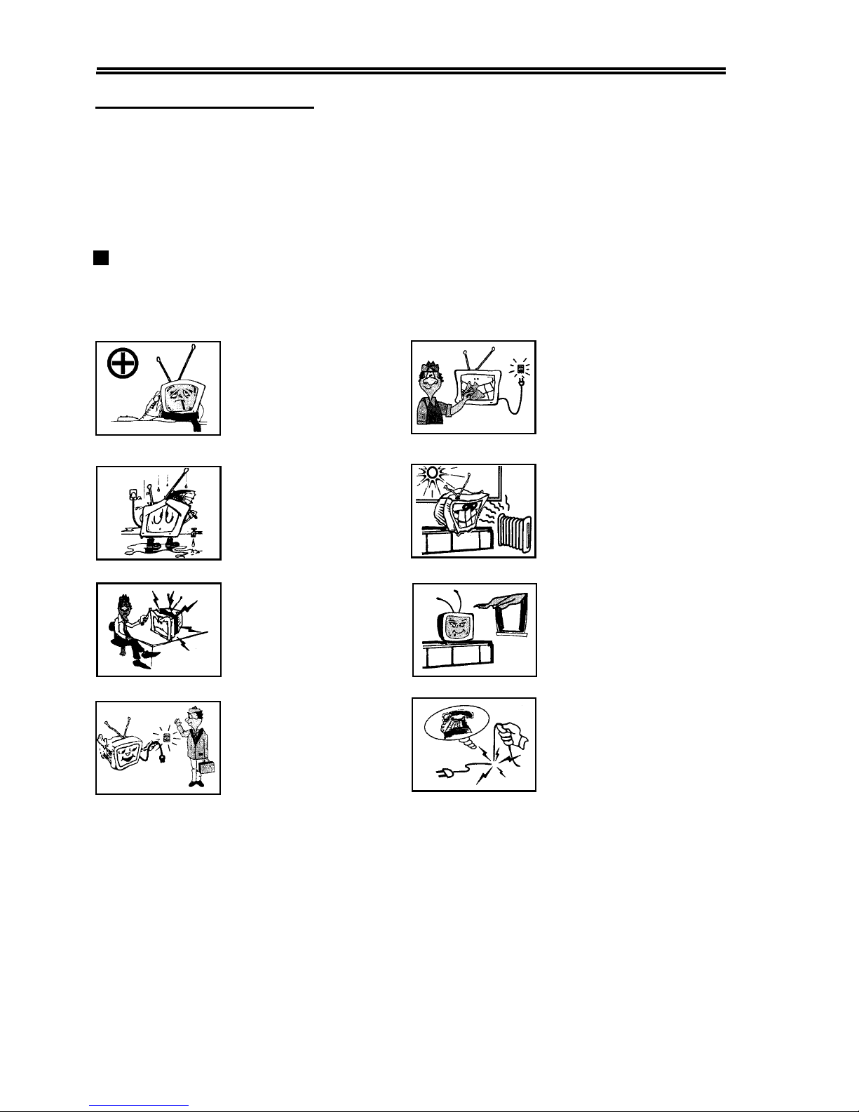
Cautions For Safety
2
Note: This TV set can be operated on an AC power of 240V, 50Hz. You should not use power
supply of the other type.
When an unusual situation
occurs, turn off the power
switch at once and remove the
plug from the wall outlet.
Contact a qualified service
department in your local area.
Do not expose the TV set to
rain or excessive moisture, to
prevent tire disaster or
electric shock. Avoid using
the set in very warm or damp
places. Never use it in a
bathroom.
There exists High Voltage in
this TV set. Do not remove
the cover to avoid danger.
The TV set should be placed
on an adequate place without
exposing it to direct sunlight
and other sources of heat to
prevent the deformation of the
cabinet or damage to
components.
When the TV set is to be left
unattended, please turn off the
power switch and remove the
plug from the wall outlet.
In order to wipe dust off the
picture tube or off the cabinet,
you should remove the power
plug from the wall outlet first.
You can wipe lightly with a
piece of dry, clean, soft cloth.
Do not cover the Ventilating
holes in the cabinet. Keep a
space of more than 5 cm from
the walls to the TV set, to
guarantee the good ventilation.
When the power cord or the
plug is damaged, please
contact a qualified service
department to get service.
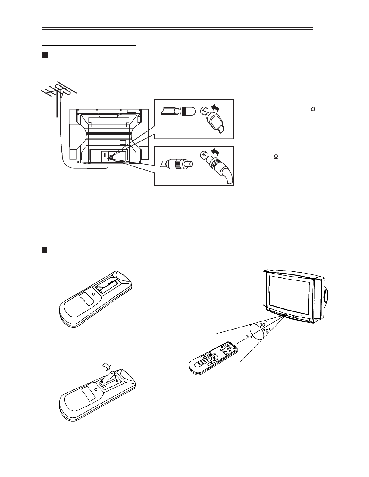
Installation and appearance
Antenna connection
To ensure a bright-coloured and clear picture, you should use an outdoor aerial or CATV
cable. If the signals are strong enough, you may use an indoor aerial.
Note:
When you connect the outdoor aerial cable to the aerial terminal on the TV set, please turn off
the power switch on the TV while connecting the antenna lead.
In thunder and lightning, weather, please disconnect the connection to the outdoor aerial to avoid
thunder/lightning strike.
Battery Installation:
1) Remove the back battery cover.
2) Insert two size AAA batteries according to
the polarity indication inside the remote
controller.
3
Effective range of the remote control
operation
1. When the remote controller is not used for
an extended period of time or the batteries
are worn out, please remove the batteries in
time to avoid battery leakage.
2. Avoid moisture and mechanical shock to the
remote controller.
Note: In case of using the
Twin-lead aerial feeder (300 )
for UHF/VHF aerial, use a 300-75
ohm adaptor (not supplied)
When using the coaxial cable (not
supplied) (75 ) for UHF/VHF
aerial, connect the plug into the
75 ohm aerial socket directly.
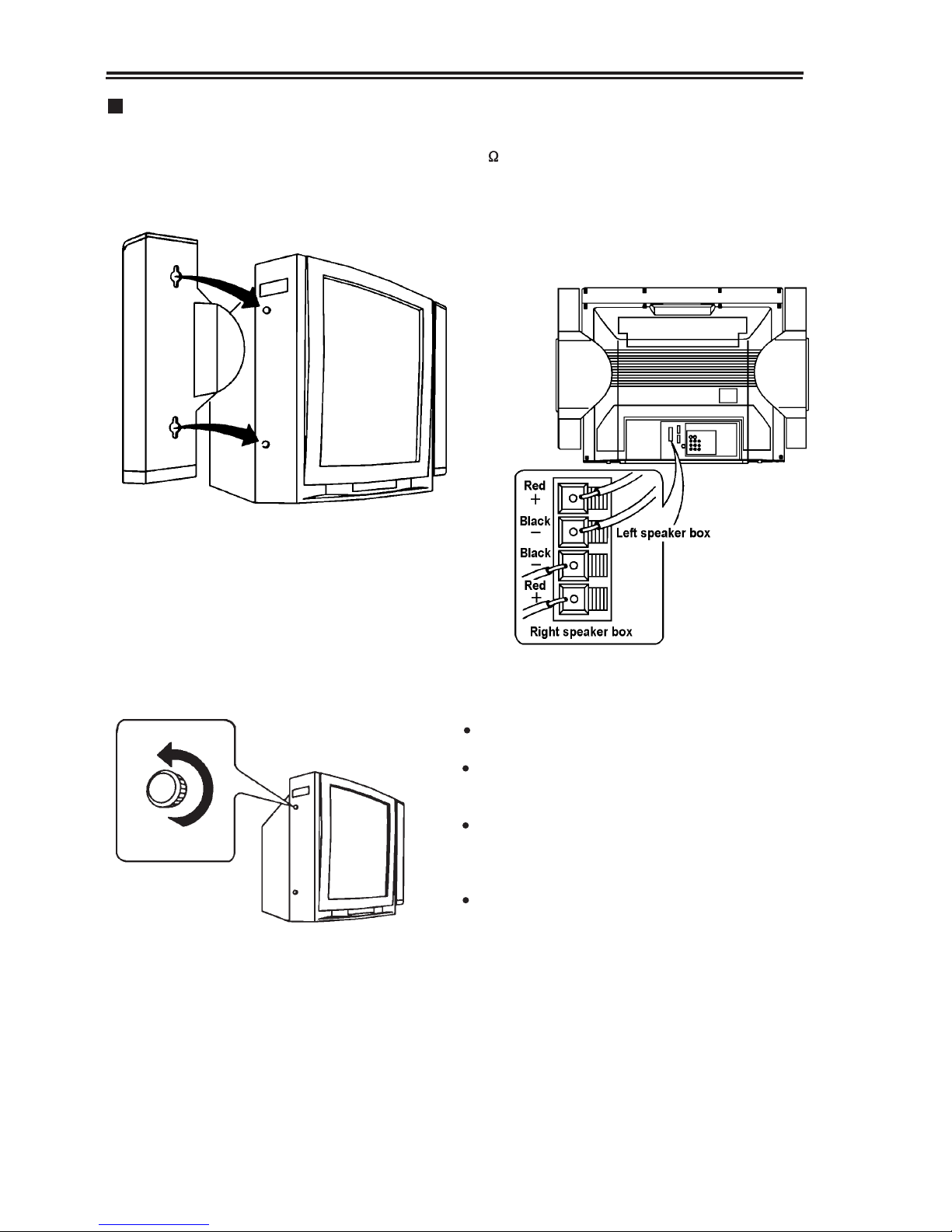
) terminals at the rear of the TV.
Red wires should be connected to the + red
terminals, while black wires to the - black
terminals
Speaker Connection
As the figure below shows, attach the left and the
right speaker to the sides of the set tightly, push
the speaker from their top to secure them.
Loosen the screws to remove the speaker
from the TV
2. Connect the speaker wires to the EXT SP (8
When connecting other speakers, you can loosen
the screws of both sides and remove the speaker
from the TV.
Attention:
Unplug the power cord from the AC socket when
connecting the speakers.
If you connect larger speakers, they must he rated
at 8 ohm impedance with normal power handling
capacity of more than 15W.
Make sure that none of the speaker wire strands
stick out, making contact with the neighbouring
speaker terminals, to prevent a malfunction caused
by a short circuit of the speaker terminals.
Before moving the TV, remove the speakers down
from the TV.
4
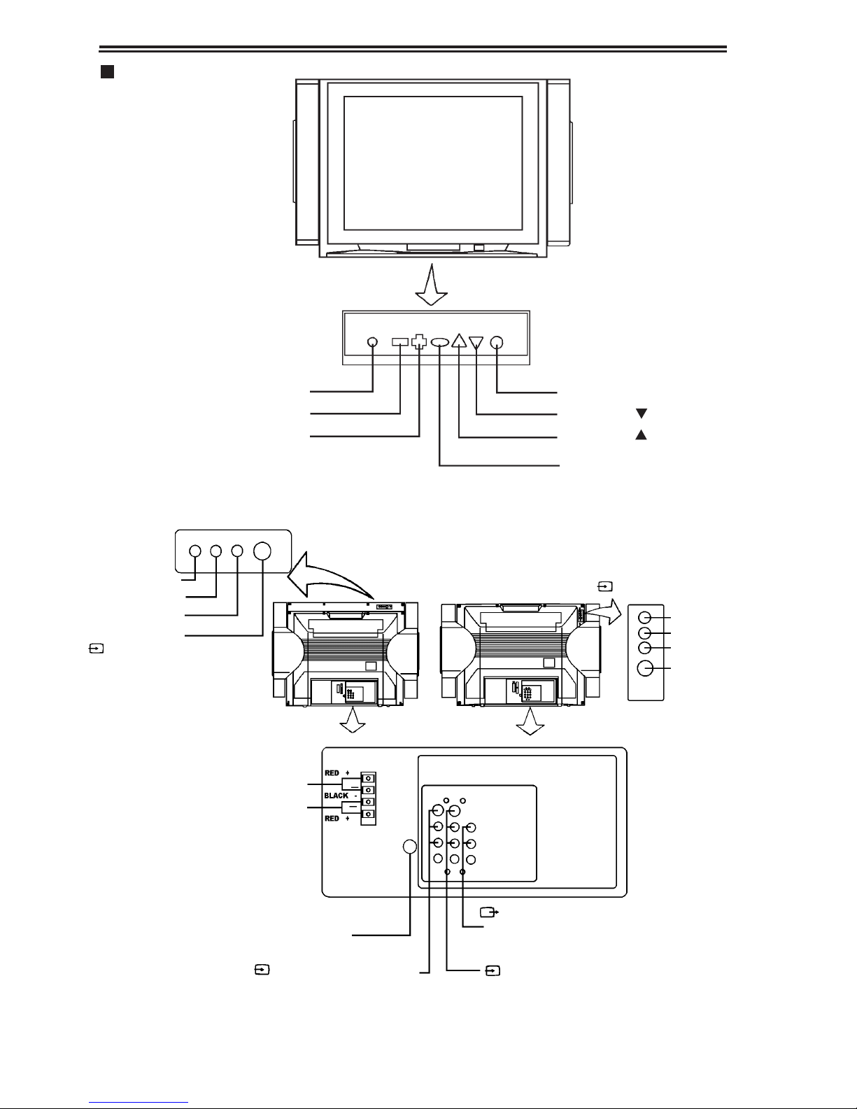
Appearance
Front view
Back view
5
VIDEO
VOLUME -
VOLUME +
SYSTEM
CHANNEL
CHANNEL
MENU
MODEL 9218 MODEL 8218
R (right sound terminal)
L/MONO
VIDEO
S-VIDEO
R
L/MONO
VIDEO
S-VIDEO
(3) VIDEO 3 input terminals
connecting to external speakers
left speaker box
right speaker box
(3) VIDEO 3 input terminals
(2) VIDEO 2 input terminals
(VIDEO, AUDIO L/MONO, R)
MONITOR output terminals
(VIDEO, AUDIO L/MONO, R)
(1) VIDEO 1 input terminals
(S-VIDEO, VIDEO, AUDIO L/MONO, R)
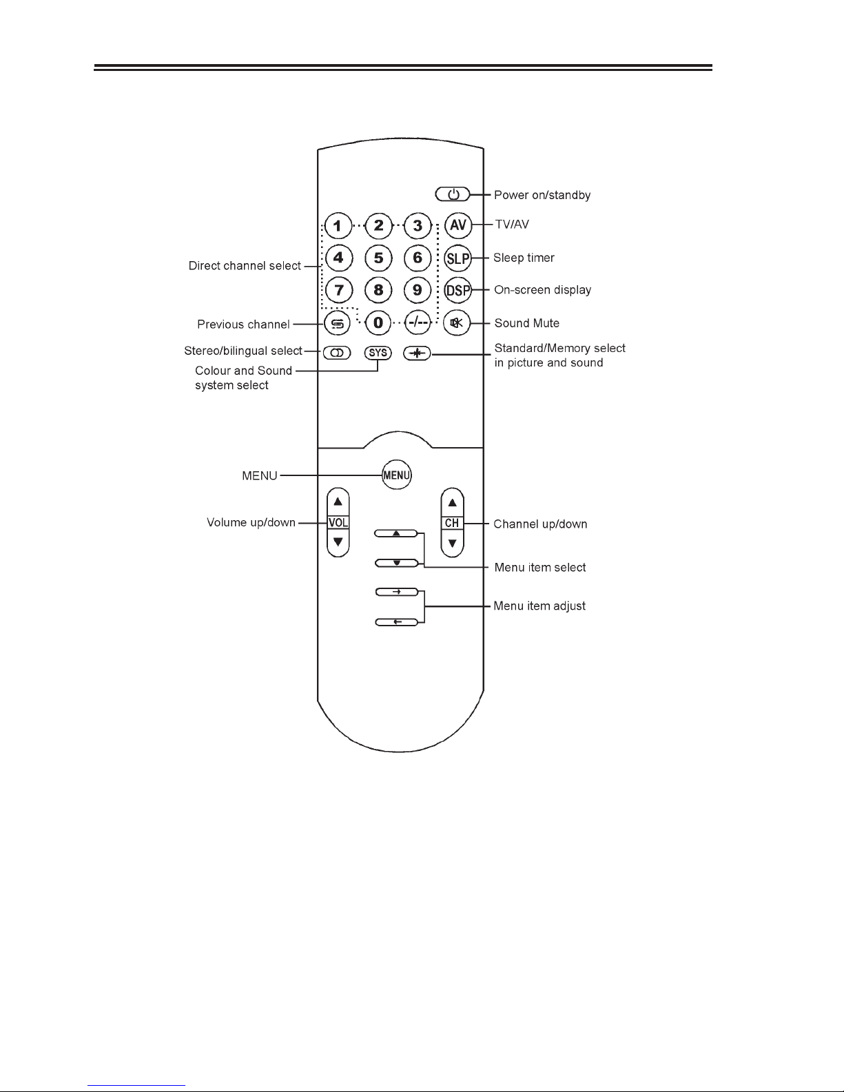
The Remote Controller
6
 Loading...