

Page 1
SUNLITE® Technical Guide
Multiwall Polycarbonate Sheet
Page 2
Content
Introduction 1
Product Range 1
Standard dimensions 1
Colors 2
Typical physical properties 2
Flammability 2
Chemical resistance, compatible sealants and adhesives 3
Arching radius 3
Wind and snow load calculation 4
Spacing and load calculations 4
Positioning of clamping profiles and fastener location 13
Preparation for glazing 14
Preparations prior to installation 15
Glazing profiles and fastening screws 15
Handling and storage 16
Cutting 16
Drilling 17
Sealing and bonding 17
Accessories 17
General recommendations for working with SUNLITE® sheets 18
1
2
Page 3
SUNLITE® Technical Guide
Introduction
This manual provides basic guidelines for selecting, handling and installing SUNLITE sheets. Due to their hollow core, preliminary
preparation and additional care are required before the actual installation. Please note these guidelines before starting and follow
them carefully.
Product Range
Product Description Application
SUNLITE®
SUNLITE® UV2
Flat multiwall polycarbonate sheet with UV protective layer
on one side.
Flat multiwall polycarbonate sheet with UV protective layer
on both sides.
Suitable for both exterior and indoor applications.
Recommended for applications that involve UV
exposure on both sides (e.g. exterior light boxes)
SUNLITE® FR Sheet with higher fire resistance rating. Recommended for applications in populated areas.
Flat multiwall polycarbonate sheet with integrated metallic
SUNLITE® Solar Control
reflective heat-blocking layer. The sheet that transmits less
Available with 25 or 30% light transmission.
Infrared radiation and reduces heat buildup.
SUNLITE® CL
SUNLITE® Smart
Flat multiwall polycarbonate sheet with advanced
SolarSmart™ tint that combines infrared heat blocking with a
clear view due to its high clarity.
Can be tailored to achieve different light and heat
transmissions.
Recommended for commercial greenhouses and
SUNLITE® Plus Flat multiwall polycarbonate sheet with anti-condensation.
closed structures with an open water reservoir, such
as swimming pools.
Notes:
1. Some features of the products above can be combined. Please contact your Palram distributor for more information.
2. All the above products are supplied with a protective masking on both sides, which clearly marks the UV protected side. Protective masking on one side only is
available upon request. The masking should be removed immediately after installation.
3. For transportation, handling and storage instructions and recommendations, please refer to Handling and Storage Guidelines for Palram Sheets.
4. SUNLITE sheets are backed by a 10 years limited warranty, available upon request.
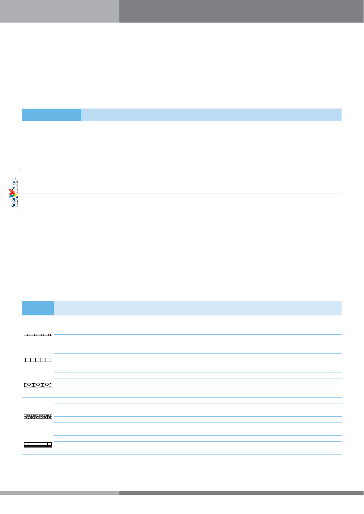
Standard Dimensions
Structure
Twin Wall
Triple Wall
X-Lite
V-Structure
7 Walls
*Other structures, dimensions and weights are available upon request. Please contact your Palram distributor for more details.
Thickness
(mm)
4 0.8 3.8
4.5 1.0 3.7
6 1.3 3.5
8 1.5 3.3
10 1.7 2.9
8 1.7 3.0
10 2.0 2.7
16 2.5 2.3
16 2.5 2.1
25 3.0 1.7
32 3.2 1.6
35 3.5 1.5
40 4.1 1.4
20 2.8 1.85
25 3.4 1.6
32 3.6 1.5
35 3.8 1.45
40 4.0 1.35
10 1.9 2.3
16 2.55 1.75
20 2.9 1.55
25 3.4 1.39
Area Weight
(Kg/m²)
U-Value
(W/m²•°K)
700 980 1050 1200 1220* 1250 1600 1800 1830 2085 2090 2095 2100
✔ ✔ ✔ ✔ ✔ ✔
✔ ✔ ✔ ✔ ✔
✔ ✔ ✔ ✔ ✔ ✔
✔ ✔ ✔ ✔ ✔ ✔
✔ ✔ ✔ ✔ ✔ ✔
✔ ✔ ✔ ✔ ✔ ✔ ✔ ✔ ✔
✔ ✔ ✔ ✔ ✔ ✔ ✔
✔ ✔ ✔ ✔ ✔ ✔ ✔
✔ ✔ ✔ ✔ ✔ ✔ ✔
✔ ✔ ✔ ✔ ✔ ✔
✔ ✔ ✔ ✔ ✔ ✔
✔ ✔ ✔ ✔ ✔ ✔
✔ ✔ ✔ ✔ ✔ ✔
✔ ✔ ✔ ✔ ✔ ✔
Width (mm) (*USA Only)
✔ ✔ ✔
✔ ✔ ✔
✔ ✔
✔ ✔
✔
✔
✔
✔
1
Page 4
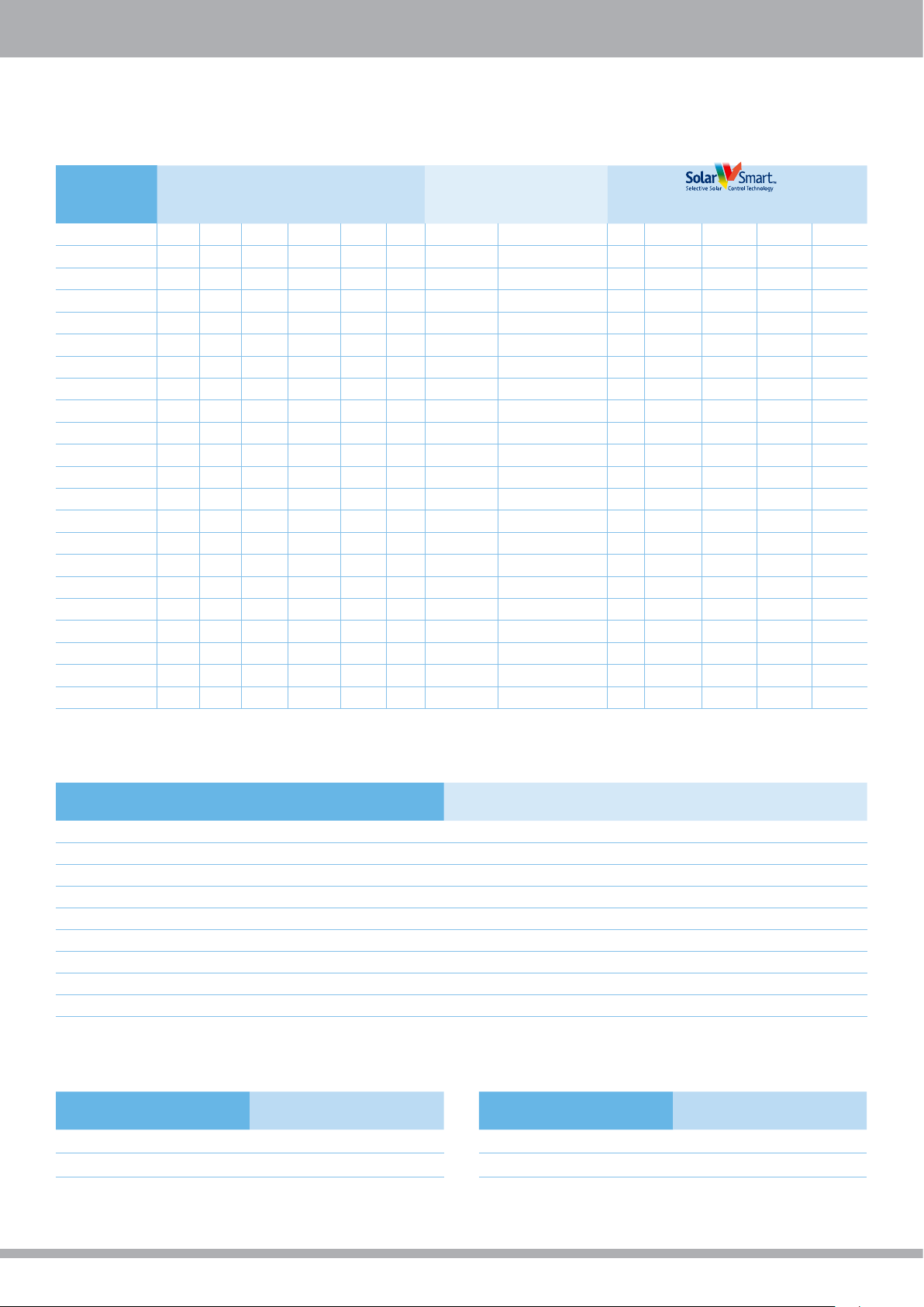
Colors*
Standard Colors Multi-Layered
Structure
Twin wall 4mm 82% 35% 30% 35% 30% 30%
Twin wall 4.5mm 82% 35% 30% 35% 30% 30%
Twin wall 6mm 80% 35% 20% 35% 30% 30%
Twin wall 8mm 80% 35% 35% 35% 30% 25% 45%/34% 60%/55%
Twin wall 10mm 79% 35% 30% 35% 30% 25% 60%/55%
Triple wall 8mm 76% 35% 48% 35% 30% 25%
Triple wall 10mm 76% 35% 48% 35% 30% 25%
Triple wall 16mm 76% 35% 48% 35% 30%
X-Lite 16mm 60% 25% 38% 35% 30%/25%
V-Structure 20mm 63% 25% 20% 10%
V-Structure 25mm 62% 30%
V-Structure 32mm 61% 20% 20%
V-Structure 35mm 60%
V-Structure 40mm 58%
X-Lite 25mm 60% 25% 15% 10% 5% 20% 20%/16% 42%/35%
X-Lite 32mm 58% 20% 15% 10% 5% 20% 20%/16% 42%/35%
X-Lite 35mm 57% 20% 15% 10% 5% 20% 20%/16% 42%/35%
X-Lite 40mm 57% 20% 15%
7 Walls 10mm 64% 45% 29%
7 Walls 16mm 64% 45% 29%
7 Walls 20mm 62% 45% 29%
7 Walls 25mm 60% 40% 22%
*Light transmission values adhere to ASTM D-1003. **Blue, Green and Solar Control are made to order only.
Clear Bronze
White
Opal
White
Diffuser
Green** Blue** Bronze/Opal
Solar Guard
(Solar Control/Opal)
Solar
Ice
Solar
Control**
CL SLT
LT = Light Transmission
ST = Solar Transmission
Smart
Green
Typical Physical Properties
Property Method* Conditions Units Value
Density D-792 g/cm³ 1.2
Heat deflection temperature (HDT) D-648 Load: 1.82 MP °C 135
Service Temperature - Short term °C -50 to +120
Service Temperature - Long term °C -50 to +100
Coefficient of linear thermal expansion D-696 mm/mm °C 6.5x10
Tensile strength at yield D-638 10 mm/min MPa 62
Elongation at break D-638 10 mm/min % >90
Impact falling dart ISO 6603/1 J 40-400
Practical thermal expansion/contraction mm/m 3
* ASTM except where noted otherwise.
Flammability
Method Classification* Method Classification*
BS 476/7 Class 1
EN 13501 B, s1, d0 ASTM E-84 Class A
* Depends on sheet type. For more information please contact your Palram distributor.
ASTM D-635 CC-1 (SUNLITE® FR)
2
Page 5
SUNLITE® Technical Guide
Chemical Resistance & Compatible Sealants
SUNLITE has good resistance to many chemicals. Some chemicals may harm the SUNLITE sheets. Detailed information about these
materials can be found at the Chemical Resistance of Palram Polycarbonate Products brochure. Please contact your Palram dealer
when in doubt about any material or chemical.
When choosing adhesives or sealants to be used during installation of SUNLITE sheets, please refer to Recommended Adhesives and
Sealants for Polycarbonate Products from the Palram websites.
For use of any adhesive or sealant not listed in the above brochure, consult with your Palram dealer to get his approval. Failure
to do so will void any and all warranties.
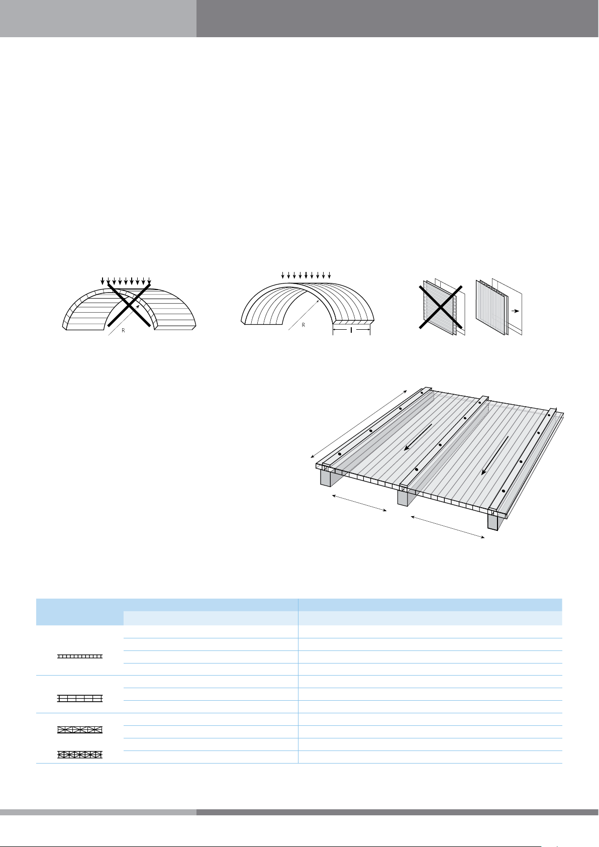
Positioning the Sheets
1. SUNLITE sheets should be installed with the rib channels sloping downwards (Figs. 1a, 1c, 2). That orientation will reduce accumulation
of dirt inside the sheet and ease gravity drainage of any condensation moisture.
Figure 1a Figure 1b Figure 1c
2. Sheets should be installed with the adjoining edges connected by a glazing profile suited to the glazing system.
3. For sheets installed in the flat, horizontal position, (roofs, overhead skylights),
a minimum slope of 5 percent is imperative, with 10 percent and above
preferable. Steeper slopes offer better rainwater drainage and self-
Length
cleaning, and reduce the risk of water and dirt infiltration through
the connectors and fastening screws. Steeper slopes also help to
diminish the visual effect of sheet deflection caused by loading.
Slope > 5%
4. Length dimension is defined as parallel to the ribs, while width
will always be perpendicular to the ribs.
Width
Arching Radius
SUNLITE sheets may be cold bent or curved up to their minimum
permitted radius, using polycarbonate’s natural tolerance for cold
Figure 2
Flat, two-sided clamped glazing
Width
forming with no need for thermal processing. Curving SUNLITE
sheet beyond this minimum permitted radius induces undue stresses and strains in the glazing sheet, causing premature failure and
will void the warranty.
Structure
Twin Wall
Triple Wall
X-Lite
V-Structure
mm Inch mm Feet Inch
Thickness Minimal Cold Bending Radius
4 5/32 700 2.30 28
6 1/4 1,050 3.40 41
8 5/16 1,400 4.60 55
10 3/8 1,750 5.70 69
8 5/16 1,760 5.80 69
10 3/8 2,200 7.20 87
16 5/8 2,800 9.20 110
16 5/8 3,000 9.80 118
25 1 5,000 16.40 197
32 1 1/4 6,400 21.00 252
35 1 3/8 7,000 23.00 276
3
3
Page 6
Wind and Snow Load Calculation
Local building codes and standards in most countries provide details for required design loads, which should be consulted before
installation. The information below is provided for general reference.
Conversion of Wind Velocity Values into Wind (or Static) Pressure
Wind Strength Level
Property Units
Moderate Strong Storm Hurricane
Wind velocity
Static pressure
Km/h 20 40 - 60 80 - 100 120 - 140(+)
m/sec 6 11 - 17 22 - 28 33 - 40
Kg/m² 2 8 - 17 30 - 50 70 - 100(+)
psf 0.4 2 - 4 6 - 10 14 - 20(+)
Snow Load: Snow load from accumulated snow cannot be disregarded. Both structure and glazing should be suitable for this extra
weight. When choosing greenhouse roofing material for snow-bound areas, a single wall corrugated polycarbonate roofing (e.g.
SUNTUF or SUNSKY) may become preferable. Please consult with your Palram distributor.
Indicative snow load Per 1.0 cm (0.4 inch) of height or thickness
Fresh, fine, fluffy snow From 0.8 to 1.9 kg/m² (0.16-0.39 psf)
Wet, watery, compacted snow From 2.0 to 8.0 kg/m² (0.41-1.64 psf)
Spacing and Load Calculations for Different Methods of Installation
1. Four Sides Clamp or Frame
This method utilizes comparatively small, separate glazing elements, cut from larger sheets. SUNLITE is put inside a four-sided frame
or supporting structures, and clamped on all sides. Clamping is done by plastic, wood or metal clamping profiles, with or without
rubber sealing strips, and fastened by nails, screws or bolts to the supporting frame. The frame itself can be made of wood or metal,
according to the design.
Clamping profile
Silicone sealant
Rubber packing strips
on both sides
SUNLITE glazing
Supporting frame
Figure 3a
Typical four sided clamp installation:
“wet” method, steel frame.
Figure 3a
Typical four sided clamp installation:
“wet” method, steel frame.
The table on top the next page presents the recommended center-to-center spans, for each type of SUNLITE sheet at various wind
or snow loads.
4
4
Page 7
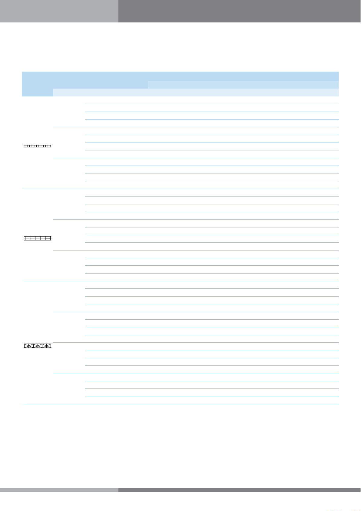
Maximum Recommended Distances Between Centers- Shorter Spans (width)
Under different ratios and loads for four sides clamped / framed flat glazing.
SUNLITE® Technical Guide
Structure
Twin Wall
Triple Wall
X-Lite
Thickness
mm Kg/m² psf mm Inch mm Inch mm Inch
6
8
10
8
10
16
16
25
32
35
Wind/snow
uniform loads
50 10 900 36 700 28 500 20
80 16 700 28 500 20 350 14
100 20 500 20 400 16 - 120 25 400 16 300 12 - -
50 10 1150 45 900 36 600 24
80 16 1000 40 800 28 480 19
100 20 900 36 650 22 450 18
120 25 750 30 600 20 - -
50 10 1250 50 1000 40 750 30
80 16 1200 47 900 30 550 22
100 20 110 43 800 24 500 20
120 25 950 37 700 21 450 18
50 10 1200 47 950 38 650 26
80 16 1050 42 750 29 510 20
100 20 950 37 650 22 470 18
120 25 900 38 650 22 480 19
50 10 1275 51 1050 41 800 32
80 16 1225 49 900 32 600 24
100 20 1125 44 750 26 550 22
120 25 900 38 650 22 480 19
50 10 1500 59 1200 47 1100 43
80 16 1300 52 1100 43 1000 41
100 20 1200 47 1050 41 900 36
120 25 1100 43 950 37 850 33
50 10 1550 61 1250 49 1150 45
80 16 1350 53 1150 45 1050 41
100 20 1240 49 1080 42 950 37
120 25 1130 44 980 38 900 35
50 10 2100 83 1700 67 1400 55
80 16 1950 76 1600 63 1650 53
100 20 1800 70 1500 59 1300 51
120 25 1650 65 1400 55 1250 49
50 10 2100 83 1850 73 1500 59
80 16 2100 83 1700 67 1400 55
100 20 2000 78 1600 63 1350 53
120 25 1850 73 1500 59 1300 51
50 10 2100 83 1875 74 1525 60
80 16 2100 83 1725 68 1425 56
100 20 2025 79 1652 64 1375 54
120 25 1875 74 1525 60 1325 52
Distance between centers (shorter span) according to ratio a:b
Ratio 1:1 Ratio 1.5:1 Ratio > 1.5:1
Notes:
1. SUNLITE 4mm twin-wall is not recommended for constructive applications and is therefor excluded.
2. Data in table according to load tests on typical multi-wall sheets and additional extrapolations.
3. Recommended spans are calculated on the basis of 1/20 maximum deflection (5%) of sheet’s width (In this case crosswise, perpendicular to the rib channels).
4. A SUNLITE glazing sheet may withstand even higher loads without buckling, however, excessive lateral shortening, created by higher deflection, may cause the
edges to slip out of their supports (pop-out).
5
5
Page 8

2. Two-Sided Clamped Glazing
This is a simpler glazing system to install, requiring no mid-sheet
fastening, using long glazing sheets, and held in place by two
glazing profiles on both longitudinal edges. It is not as strong, and
permitted width is limited (the width direction of a multi-wall sheet
is more vulnerable to loads, span-wise, especially the thinner, square
ribbed 6 , 8 and 10 mm sheets).
Side clamp
(Glazing profile)
SUNLITE glazing
Figure 4
Flat, two-sided clamped glazing
Supporting rafter
Maximum Width of SUNLITE Sheets in Two Sides Clamped Flat Glazing
Twin Wall Triple Wall X-Lite
Uniform Load 6 8 10 8 10 16 16 25 32 35
Kg/m² psf mm Inch mm Inch mm Inch mm Inch mm Inch mm Inch mm Inch mm Inch mm Inch mm Inch
50 10 450 18 540 21 680 27 575 19 700 25 990 39 1100 44 1250 50 1200 48 1200 48
80 16 320 13 430 17 500 20 450 15 525 18 900 36 1050 41 1100 43 1000 38 950 38
100 20 - - 400 16 450 18 400 14 475 17 800 32 1000 35 1050 41 950 37 875 35
120 25 - - - - 400 16 - - 425 14 700 28 975 38 1000 40 900 36 800 32
Note: The notes attached to the previous table, Maximum Recommended Distances, also apply here.
3. Two-Sided Clamped Arched Glazing
1. SUNLITE sheets can be curved into arches within the permitted radius
(see “Arching Radius” on page 3) without damaging their mechanical
Clamping/glazing profile
performance. Moreover, internal stresses induced by curving give the
sheets extra strength and rigidity in both directions, like pre-stressed
concrete elements.
SUNLITE glazing
2. Rigidity and support spans increase as the curve radius is reduced (down
to the minimal permitted radius). Shallow curving should be considered
to be similar to flat panels, while a deep curve significantly adds to the
bridging ability.
Figure 5
The table in the next page shows the growing rigidity from the curving of SUNLITE, at various uniform loads.
Supporting
arch
6
6
Page 9

Maximum Recommended Spans between Arched Supports
According to radius of curve and load for two sides clamped glazing.
SUNLITE® Technical Guide
Structure
Twin Wall
Triple Wall
X-Lite
Thickness
mm mm Inch mm Inch mm Inch mm Inch mm Inch
6
8
10
8
10
16
16
25
32
35
Sheet curvature
radius
50 Kg/m² 10 psf 80 Kg/m² 16 psf 100 Kg/m² 20 psf 120 Kg/m² 24.6 psf
1050 41 2000 79 1730 68 1420 56 1020 40
1500 59 1470 58 1090 43 890 35 660 26
1800 71 1140 45 860 34 690 27 580 23
2200 88 810 32 690 27 - - - 2800 110 500 20 350 14 - - - 4000 158 500 20 350 14 - - - 6000 236 500 20 350 14 - - - 1400 55 1650 65 1450 57 1320 52 1170 46
1800 71 1420 56 1270 50 1070 42 890 35
2200 88 1090 43 890 35 710 28 600 24
2800 110 840 33 620 19 450 18 - 4000 158 600 24 500 19 - - - 6000 236 570 23 480 19 - - - 1750 69 1630 68 1420 56 1170 46 1020 40
2200 88 1320 52 960 38 810 32 660 26
2800 110 890 35 650 26 600 24 550 22
4000 158 750 29 550 22 500 20 450 18
6000 236 700 27 520 21 500 20 420 18
1760 70 1320 52 1170 46 980 39 750 30
2200 87 1025 41 780 31 580 23 520 21
2800 110 750 30 570 23 400 16 - 4000 158 500 20 450 18 - - - 6000 236 480 19 400 16 - - - 2200 88 1220 48 880 35 720 29 580 23
2800 110 780 31 580 23 500 20 450 18
4000 158 620 25 500 20 450 18 400 16
6000 236 550 22 450 18 400 16 - 2800 118 1850 73 1650 65 1450 57 1200 48
4000 158 1450 57 1220 48 940 37 850 34
6000 236 1050 42 1000 40 850 34 800 32
3000 120 1750 69 1600 63 1500 59 1400 55
5000 200 1350 53 1200 47 1100 43 1000 39
5000 197 1650 64 1450 57 1400 55 1350 53
6000 236 1550 61 1350 53 1300 51 1250 49
6400 252 1650 64 1550 61 1350 53 1300 51
8000 315 1550 61 1450 57 1250 49 1200 47
7000 276 1650 65 1550 61 1350 53 1300 51
8200 322 1550 61 1450 57 1250 49 1200 47
according to wind/Snow loads below
Recommended (center-to-center) Distance between Supporting arches
Notes:
1. A hyphen sign in the table (-) means that the sheet cannot be used at the relevant range.
2. Generally a span of less than 600 mm (24 in.) is impractical for this installation configuration.
3. The lowest radius that appears in the upper row of every sheet group in the table is the minimum permitted cold bending radius for that specific sheet type.
7
7
Page 10

4. “Roofing & Cladding” Installation Method
This is a simpler, more practical method, resembling the one used for single-wall, corrugated plastic (or metal) sheets. It employs
longer strips, with wider dimension. Length is as long as possible without excess deformation by thermal expansion. SUNLITE sheets
are laid on top of the purlins, with rib channels directed down the slope, perpendicular to the
purlins. Span between purlins is determined by the load and deflection characteristics
of the specific SUNLITE sheet.
1. The sheets are connected to each other by long connecting elements.
2. The wide variety of these connection methods falls into two main
categories: “wet” or “dry” installation systems. The connecting elements
(made of aluminum, sheet metal or plastic- rigid PVC or polycarbonate) are
designed as connectors, not as load supporting members. They connect the
sheets to each other, achieving one unified watertight exterior shell. Additional
strength and rigidity achieved through them is an added bonus.
Basic inverted “H” polycarbonate connecting profile
An old and simple form enabling a lengthwise (side by side) connection between twin/multi-wall sheets. It
is sometime offered with a specific size profile for each sheet thickness, or in versatile, more flexible design enabling the use of one
profile with 2 consecutive thicknesses (4-6 & 8-10 “H” profiles). This connecting method is practically inappropriate for the thicker
SUNLITE panels.
1. “Dry” method: The edges on both sides are inserted into the profile, holding
the sheets by “dry” mechanical friction, with the sheets on both sides fastened
to the structure, along the purlins, by fixing screws, about 500-600 mm (20-24
inches) apart.
2. “Wet” method: both the profile channels are half-filled with silicone, which
acts, after installation and curing, both as sealer and adhesive. It may offer better weatherproofing at shallower slopes, than the “dry”
system, but is very difficult to install properly and cleanly (Figure 7).
Figure 6
Figure 7
Basic, inverted H polycarbonate connecting profile
Notes:
1. The connector itself is not fixed to the purlins.
2. Both systems are basic and disclose several shortcomings: difficult and bothersome installation, plain looks, weak and imperfect
connection and sealing. Installation may prove to be lengthy and messy for inexperienced hands. They are, however, considered the
cheapest.
Two-part polycarbonate connecting profile, which is made of the following:
1. A lower base profile, usually the more rigid of the two, on which the edges of the adjoining sheets are placed. Usually the base
profile is fastened to the purlins by screws through the middle, with both edges free, letting the sheets slide easily due to the thermal
expansion and contraction process.
2. The upper part, usually more flexible than the base, clips on the base profile by hand pressure, holding both sides of the adjoining
sheets in place by mechanical pressure.
This type is easier to install, more reliable in holding the sheets and sealing the connection. It is used, mostly, in “dry” installation, but
could be assisted by silicone on the upper and lower profile. “Wet” installation like this is difficult to keep clean during installation and
with long sheets may lose its effectiveness due to excessive expansion.
Figure 8a Figure 8b Figure 8c
Figure 8
Drawing of typical two-part polycarbonate connecting profiles currently used
8
8
Page 11

SUNLITE® Technical Guide
Combination of metal and plastic two-part connecting profile
Offers added strength and rigidity. The lower part of the profile is made of metal- (mostly aluminum ), and the upper part is made of
plastic (rigid PVC or polycarbonate), clipped on top of the metal profile, pressing on the edges of the two adjoining sheets.
Figure 9
Description of Typical Two-Part Plastic and Metal Connecting Profiles Currently Used
Wood connecting profiles
Developed from wooden window frames, support the installed SUNLITE sheets. They are usually used together with the “wet” system,
with rubber packing strips and silicone sealant. Lengths are generally limited by the nature of wood. If long, laminated wooden rafters
are used, they usually come with one or more of the other connecting solutions below.
Aluminum
Wood
Silicone sealant
Rubber Strip
Wood
“Dry” system “Wet” system
Figure 10
Description of Typical Two-Part Wood Connecting Profiles Currently used in the Market
Metal connecting profiles
Comprise the largest group of connecting profiles. They come in wide variety of designs, are made from aluminum or steel, in “dry” or
“wet” systems, and in plain or sophisticated detailing and finish. Some profiles are equipped with built-in drains, EPDM rubber weather
strips, concealed fixing screws, and high-end finish, for more luxurious structures.
Figure 11a Figure 11b
Figure 10
Typical two-part metal system connecting profiles currently used.
9
Silicone sealant
Steel
support
Figure 11c Figure 11d
Steel clamping bar
Epdm sealing/padding
strips on both sides.
9
Page 12

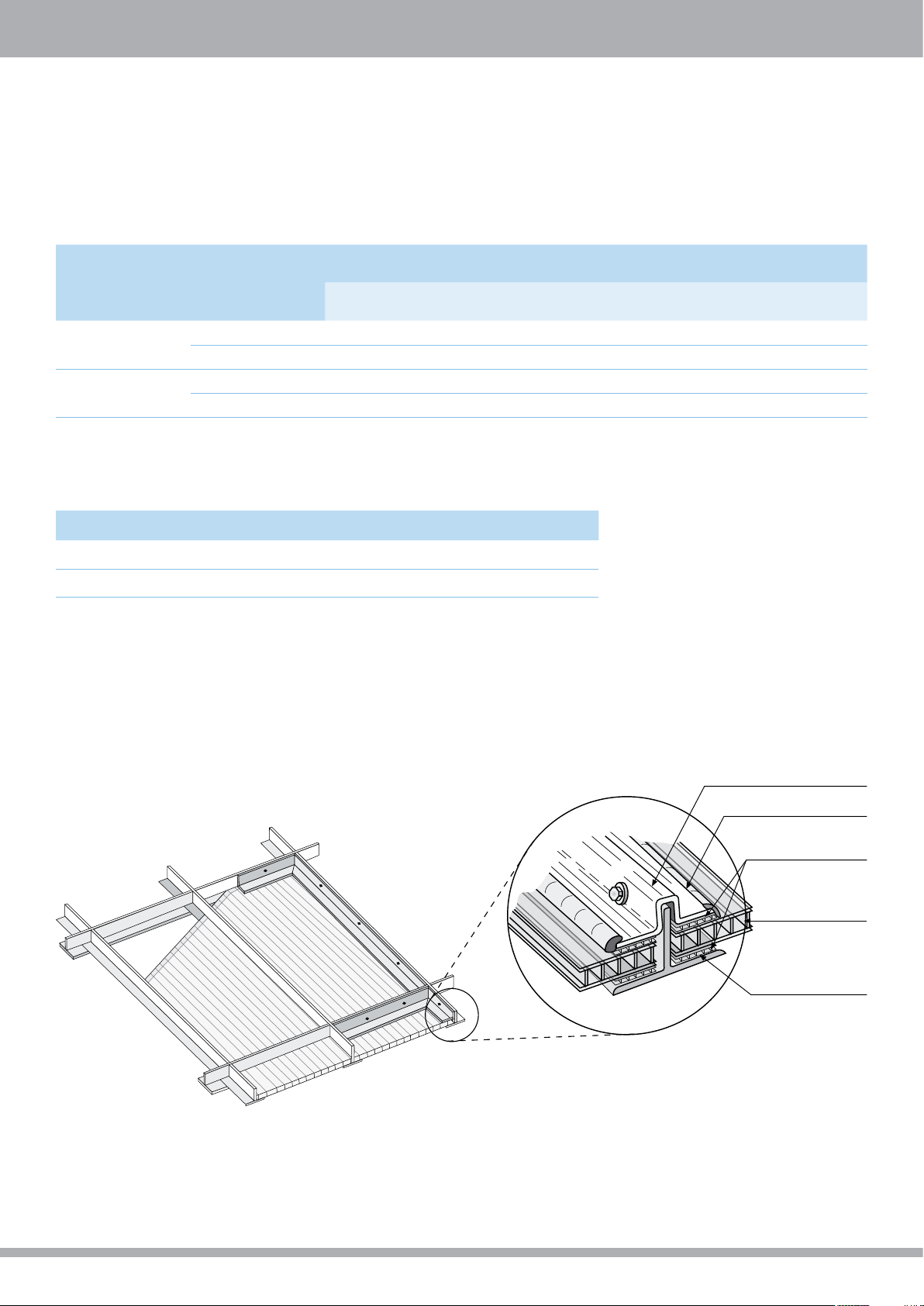
Mid-Sheet Fasteners
(Not recommended for DIY Applications)
1. A wider sheet has to be fastened to the supporting structure
by additional fastening along its width, as the connectors
on both longitudinal sides are not enough to hold the sheet
down, against the uplift force it has to withstand.
2. Fastening is usually done by screws, inserted along the
supporting internal purlins, spaced about 500mm (20in.) apart.
Figure 12
Schematic isometric view
of partial installation with
mid-sheet fasteners
3. Along the edge purlin, the fastening screws should be inserted about 300 mm (12 in.) apart.
4. A hole must be pre-drilled into each screw location. The diameter of that hole should be 2 mm larger than that of the screw, to
allow for thermal expansion movements. In case of dark colored sheets predrill even larger holes, and use wider fastener washers.
5. An electric screwdriver with an adjustable clutch should be used to tighten the screws. Avoid excess overtightening, which might
induce undue internal stresses, causing premature failure and buckling of the sheet. Pay attention to insert the screws perpendicular
to the material face, as inclined insertion could damage the sheet and/or result in leaks.
Figure 13
Typical installation screws
and obligatory washers
Figure 13a
Incorrect - Overtightening
Figure 13a
Self-tapping screw
6. Use of self-tapping or self-drilling screws is recommended. In case of wooden structures, suitable wood-screws should be used.
All the screws should be corrosion resistant, with at least heavy-duty hot-dipped galvanized finish, or stainless steel (if used in an
extremely corrosive environment). The screws should be 6.35mm (1/4in.) diameter, with length according to sheet thickness, type of
washer and type of supporting structure.
7. Each screw should be fitted with a conical corrosion resistant steel washer, with specifications as the screws above or of aluminum,
at least 1mm (0.04 in.) thick, 25mm (1 in.) diameter, with a Specially Shaped integral rubber gasket, EPDM (see Palram special washer/
gasket fig. 13g). The screw should be tightened carefully, with no distortion of the washer and rubber gasket, or the flat face of the
sheet Palram will supply the suitable fasteners and washers with the SUNLITE sheets unless required otherwise.
Figure 13b
Self-drilling screw
Figure 13b
Wood screw
25mm special washer/gasket
Figure 13b
Correct
Figure 13g
Figure 13c
Incorrect - Non-perpendicular
drilling and insertion
10
10
Page 13

SUNLITE® Technical Guide
8. Screw buttons: Improved performance can be obtained by replacing the
washers with special plastic screw buttons, fitted with a suitable rubber gasket,
with or without a closing cap. They fit the thickness of each type of sheet (6, 8,
10, 16 mm, and possibly 25 mm), differing by sleeve length. Their advantage:
the sleeve prevents excessive tightening and local squashing around the
screw, and is softer on the sheet, reducing risk of tear or shear around the
screw’s stem. They also offer a seal between the fastener hole and the open
channels of the sheet, preventing possible infiltration of water and dirt into
the internal space of the sheet. Screw buttons can suit the 6.35mm (1/4 in.)
screws mentioned above, although it is recommended to use slightly longer
screws to accommodate the button thickness.
Palram recommends perforating SUNLITE for fastening as little as possible, and
prefers the use of clamped edge installation. Palram recommends that the
use of fastening screws in a glazing system, even with plastic buttons, should
be limited to economical, price conscious projects only. Two or four-sided
clamped glazing is a preferred choice.
Optional cover
Design spans between Supporting Purlins
According to Designated Loads for the Roofing and Cladding Method
Max. Recommended Spans between Support Purlins - Flat / Slightly Curved Roofing/Glazing
Figure 14
>30 mm
>2 mm more than
diameter of button stem
Rubber gasket
Plastic button
Fastening screw
Thickness
Distance (center-to-center) between supporting purlins - according to wind/Snow loads below
Structure
mm mm Inch mm Inch mm Inch mm Inch
6 900 36 800 32 650 26 500 20
Twin Wall
Triple Wall
X-Lite
Notes:
1. Span calculation is based on general professional know-how, previous experience & specialized expertise with this type of products.
2. Spans depicted are drawn from loading tests and extrapolations based on L/20 deflection (5%) at the specific span and load using continuous multi-span
supports. The values refer to mid-spans. Edge-spans (lower & upper ends) should be approx. 20% smaller.
3. SUNLITE panels can withstand higher loads and/or wider spans without failure. However the involved deflections will exceed L/10 (10%) of the span, which is
unacceptable in most cases.
Curving SUNLITE sheets gives them higher strength and rigidity, as in the case of two-sides clamping described in the next page.
8 1150 46 1000 40 850 34 650 26
10 1250 50 1150 46 1050 42 900 36
8 1120 44 970 38 820 32 620 25
10 1220 48 1125 45 1020 41 870 35
16 1600 64 1450 58 1250 50 1130 45
16 1650 65 1500 59 1300 51 1180 46
25 1850 74 1700 68 1550 62 1425 56
32 2050 82 1900 76 1750 69 1600 63
35 2075 82 1925 76 1775 70 1625 64
50 Kg/m² 10 psf 80 Kg/m² 16 psf 100 Kg/m² 20 psf 120 Kg/m² 25 psf
11
11
Page 14

Maximum Recommended Distances between Support Purlins
For Curved Roofing/Cladding, According to Curvature Radius and Load.
Structure Thickness Sheet curvature radius
mm mm Inch mm Inch mm Inch mm Inch mm Inch
1050 41 2000 79 1730 68 1420 56 1020 40
1500 60 1570 62 1570 62 1200 48 1200 48
1800 72 1420 56 1420 56 1150 46 1150 46
Twin Wall
Triple Wall
X-Lite
6
8
10
8
10
16
16
25
32
35
2200 86 1380 55 1380 55 1150 46 1150 46
2800 110 1260 50 1260 50 1100 44 1100 444
4000 158 1150 46 900 36 850 34 780 31
6000 236 900 36 800 32 650 26 500 20
1400 55 1570 62 1570 62 1570 62 1570 62
1800 72 1880 74 1420 56 1420 56 1420 56
2200 86 1730 68 1380 55 1380 55 1380 55
2800 110 1470 58 1470 58 1250 50 1100 43
4000 158 1250 50 1150 46 1050 40 900 32
6000 236 1150 46 1000 40 850 34 650 26
1750 69 1885 74 1885 74 1885 74 1885 74
2200 88 1725 68 1725 68 1725 68 1725 68
2800 110 1470 58 1470 58 1250 50 1100 43
4000 158 1250 50 1150 46 1050 40 900 32
6000 236 1150 46 1000 40 850 34 650 26
1760 70 1420 55 1420 55 1380 53 1380 56
2200 86 1380 53 1380 53 1380 53 1250 49
2800 110 1380 53 1380 53 1250 49 1070 42
4000 158 1150 46 1050 42 1050 42 750 30
6000 236 1100 44 960 38 825 33 625 25
1800 72 1885 74 1885 74 1885 74 1885 74
2200 86 1725 68 1725 68 1725 68 1725 68
2800 110 1750 69 1750 69 1750 69 1465 58
4600 158 1570 62 1570 62 1260 50 1260 50
6000 236 1260 50 1180 47 1075 42 900 36
2800 110 2100 83 2050 81 2000 79 1950 77
4000 158 1750 69 1700 67 1650 65 1600 63
6000 236 1600 63 1400 56 1250 50 1150 46
3000 118 2125 84 2075 81 2025 79 1975 77
4000 158 1800 71 1750 69 1700 67 1650 65
6000 236 1600 63 1400 56 1250 50 1150 46
5000 197 1300 90 2050 80 1770 70 1500 59
6000 237 2100 69 1850 73 1570 62 1300 51
6400 252 2200 86 2050 80 1770 67 1500 59
8000 315 2100 82 1950 76 1670 65 1400 55
7000 276 2200 86 2050 80 1770 67 1500 59
8200 323 2100 82 1950 76 1670 65 1400 55
Recommended (center-to-center) Distance between Supporting arches according
to wind/Snow loads below
50 Kg/m² 10 psf 80 Kg/m² 16 psf 100 Kg/m² 20 psf 120 Kg/m² 24.6 psf
Notes:
1. SUNLITE 4mm twin-wall is not recommended for constructive applications and is therefor excluded.
2. The specified spans are based on L/20 deflection (5%) at the specific span and load, using continuous multi-span supports. The values refer to mid-spans.
Edge-spans (lower & upper ends) should be approx. 15-20% smaller.
3. Spans depicted in all but the largest radii (6.00-8.00 m) derive from division of a full 180º barrel vault of the specific radius into equal size sectors. For instance - an
arch with 1.10m radius is divided into 2 equal parts of 1.73 m length. An arch of 1.50 m radius is divided into 3 parts each 1.57 m long, and so on)
4. Curved SUNLITE is more rigid and allows for a much wider span than in flat installation, especially in smaller radii. Rigidity and strength are reduced as the radius is
increased (for same type of panel). A lightly curved panel behaves almost the same as a flat one.
12
12
Page 15

SUNLITE® Technical Guide
Figure 15
Schematic description of standard
curved roofing in a vault.
Connecting profiles fastened to purlins
General Notes for Structural Design
1. The recommended support spacing, as specified in the load/span tables, should not supersede the requirements of local structural
and construction codes. The final values are to be dictated by actual conditions on site and engineering design.
2. The end spans, i.e. the distance between the edge support (or purlin) and the first internal purlin should be up to 80 percent of the
commonly recommended span for this load and type of sheet, or the value dictated by the design engineer.
SUNLITE glazing
Supporting arched structure
Supporting purlins
Positioning of Clamping Profiles and Fastener Location
1. Using the four-sided clamped glazing system, the support bars should be underneath (or inside), and the glazing clamps on top (or
outside). SUNLITE must be installed with the clamping profiles covering all four edges of the sheet. (These are load-bearing elements,
which connect the glazing to the supporting structure, transferring loads from the glazing to it.)
2. Using the two-sided clamped glazing system, the support bars (and glazing clamps) should be installed covering the two longitudinal
edges of the sheet, parallel to the rib channels. (Again, these are load-bearing elements, connecting the glazing to the supporting
structure, transferring loads from the glazing to it.)
3. Using the roofing/cladding method, glazing connectors (of any version) should be installed on both long sides of each sheet (parallel
to the rib channels). Their main duty is connecting adjoining sheets. They may assist transferring loads to the structure, but here the
fastening screws transfer most of the load to the supporting structure (the purlins). The screws, with their metal washer and rubber
gaskets, should be inserted along the length of the supporting purlins, about 500-600 mm (20-24 in.) apart and 300-400 mm (12-16
in.) at the edge purlin. When using metal glazing connectors, they are positively fastened to the purlins.
When using polycarbonate connecting-profiles, some types are fastened and others do not. In that case, the fastening screws will be
placed on both sides of the connector, about 200-250 mm (8-10 in.) on each side.
13
13
Page 16

Preparation for Glazing
Determination of Rabbet Depth and Thermal Expansion Allowance
These parameters depend on the SUNLITE sheet dimension, and relate to the four sides of the sheet (four-sides clamping system), or
to the two edges parallel to the rib channels (two-sides clamping system).
1. Allowance for expansion - SUNLITE roughly expands 3mm for every meter (/ in. per 3 / ft.) of length (or width) for a service
temperature range of about 50°C (90°F), the practical working range in most cases. For a sheet of 1m (or 40 in.) wide, 1.5m (60 in.) long,
a net allowance of 3 mm (width) and 5mm (length) should suffice in theory. We recommend doubling this allowance for practical
reasons. Allowance should be divided between both sides of the sheet. When the ends of panels are protected by a recessed ‘U’
channel, allow suitable internal space for thermal expansion.
2. Edge Engagement: (the overlap of the glazing over its frame).
3. Rabbet Depth: (expansion allowance + edge engagement). Palram recommends a rabbet depth of at least 20 mm
(0.8 in.) for widths up to 1.0 m (40 in.) and a depth of 25-30 mm (1.0 - 1.2 in.) for wider spans.
Wooden frame
a
b
Wooden clamping
profile
Silicone sealant
SUNLITE sheets
Rubber sealing
strip
Legend
a = Expansion allowance
b = Edge Engagement depth
c = Rabbet depth: a+b
Fastening screw
Figure 16b
“Wet” Glazing
Figure 16c
Schematic Sketch of Rabbet depth and Expansion Allowance (”Wet” and “Dry” methods)
a. Sheet width
b. Sheet length
c. Sash (frame) width
d. Sash length
e. Edge Engagement depth (overlap)
f. Thermal expansion allowance
g. Rabbet Depth e + f
a
Figure 16b
“Dry” Glazing
Top aluminum
b
glazing profile
Rubber sealing
profile/gasket
SUNLITE sheets
Sealing gasket
Bottom aluminum
glazing profile
Fixing screws
Supporting
steel beam
14
14
Page 17

SUNLITE® Technical Guide
Preparations Prior to Installation
1. Ensure smaller thermal expansions by installing sheets - especially colored sheets - at ambient temperatures of 10-25 °C (50-77 °F).
It is generally recommended to avoid installing sheets at colder or hotter temperatures.
2. Peel off the protective film at both open ends of the sheet (the width sides) to about 80-100 mm (3.5-4 in.) from the edges of the
sheet, to enable taping of the aluminum sealing tape. If a factory installed temporary seal is taped over the open ends, it should be
removed prior to the installation of the aluminum tape. Tape the sealing tape straight along the open-end side, so it will cling well
and evenly to both sides of the sheet, making sure that all the open ends of the rib channels are properly sealed.
3. Peel off the masking along the edges of length sides at both sides of the sheet, for about 80-100 mm (3.5-4 in.) from the edges,
preparing the sheet for the insertion into the connecting profiles or the glazing frame.
4. Remove the underside masking just prior to the actual installation on the roof. Premature removal of protective film may result in
damage to the sheet during handling.
5. Remove the upside, exterior protective film as soon as the installation of the whole glazed area is completed, or very short time
afterwards. Failing to do so would expose the protective film to direct sunlight that may fuse it to the sheet’s face. This will result in
difficulty to remove the protective film due to deterioration of the film, and ultimately void the warranty.
Impermeable
tape
Figure 17a
Partial or Complete
Removal of Protective Film
Prior and after Installation
6. Ensure the use of the proper type of sealing tape according to the application used, verifying that the prepared sheets are mounted
correctly.
Please note: In case of curved installation, where both open ends are situated at the bottom - apply the ventilated tape on both ends.
Take care to protect the sealing tapes at both ends from mechanical damage by covering the edges with aluminium U-profiles, or
cover them with polycarbonate U-shaped profiles (Fig-17c).
Installation of Sealing Tape
Figure 17b
on Open Ends of Sheet
Figure 17c
Installation of Impermeable Tape at Top of the Sheet and
Installation of Ventilated Tape at the Bottom of the Sheet
Ventilated
filter tape
U-protective
end cap
Glazing Profiles & Fastening Screws
Type of glazing/clamping profile used in the installation of SUNLITE sheets, differs according to the glazing system chosen:
1. Framing profiles are similar in concept and detail to those used in fixed glass windows, curtain walls and skylights, made of wood,
steel or aluminum, but wider, allowing for the larger Edge Engagement depth required for SUNLITE. The frames are prepared in advance,
and glazing is done after they are all in place, along with completion of the other finishing jobs. (See Figures 3a, 3b).
2. Two and four-sided clamped glazing employ practically the same profiles used for framing, as used in curtain walls and skylights.
Almost all are prepared prior to the glazing work, and just the clamps, the rubber packing profiles (and silicone sealant in ”wet” glazing)
are installed along with or after the glazing is in place.
3. The roofing and cladding glazing installation method installs SUNLITE over the supporting skeleton, rafters and purlins. The glazing
profiles, which are usually flatter by design, consist of top and bottom parts, made of polycarbonate, rigid PVC or a combination (a
bottom aluminum profile and top profile made of polycarbonate, or rigid PVC). SUNLITE sheets and their connecting profiles (also
acting as glazing profiles) are installed together, advancing step by step. Most profiles are flexible enough to be easily shaped into
curves by hand, when installed over curved structures, enabling inexpensive implementation of curved glazing.
15
15
Page 18

Handling and Storage
1. SUNLITE sheets should be transported and stored horizontally, on a flat, sturdy pallet
whose dimensions are equal to or larger than the sheets themselves. The sheets must be
secured and fastened to the pallet during transportation and handling on site. It is possible
to stack the sheets with the longer sheets at the bottom and the shorter on top, leaving no
unsupported overhang.
2. While moving a pallet with a forklift, always use forks as long as the sheets’ width. Shorter
forks on a wider pallet may cause damage to the sheets.
Figure 18
3. SUNLITE sheets leave the factory in packages, wrapped in white, watertight polyethylene.
The wrapping should be taken off as close to the actual time of installation as possible. Storage of the sheets should be in a covered,
dry, ventilated place, away from direct sunlight and rain.
4. Avoid leaving the sheet pallet in the rain, even if still wrapped, for extended periods, as water may condense inside the hollow
core. Extended exposure to direct sunlight may cause heat buildup, softening the protective film, fusing it to the sheet face, making
removal difficult or impossible.
5. Avoid leaving the sheets stored unwrapped, with their ends open, for more than a few days, as dust may collect inside the hollows.
6. Important! Never cover the pallet with, or place on the pallet, materials that collect heat or are good heat conductors
(e.g. dark objects, metal profiles or pipes, steel sheets etc.) They may collect and deliver excess heat, and damage the sheets.
7. When necessary to store the pallet in the open, cover it with a white opaque polyethylene sheet, cardboard, or any other insulating
material, taking care to cover the pallet completely.
Cutting
1. A. SUNLITE sheets can be cut with standard wood or metal workshop equipment. Saw blades designed especially for plastic yield best
results. A circular saw (fixed or portable, with small teeth suited for hardwood), rotating at high speed, band saw or a jigsaw (best for
short, complex cuts) can all be used, taking care to advance the blade slowly. A hand and hacksaw may also be used for local cutting.
2. Always support the sheet in the vicinity of the cut and clean (with compressed air and/or by a vacuum cleaner) the dust and debris
generated by the cutting. Running clean compressed air through the hollow channels, blowing away sawdust and shavings inside
is a good practice.
3. Sheets of low and intermediate thickness, with modest dimensions, can be cut (taking the appropriate precautions) with a short,
thin, sharp blade. A special cutting-wire hand tool may also be used, to make lengthwise cuts.
Figure 19
16
16
Page 19

SUNLITE® Technical Guide
Drilling
1. Drilling can be carried out with drill bits intended for metal. When pre-drilling for a fastening screw, the hole’s diameter should be 2
mm larger than that of the screw used. As when cutting, always support the sheet in the vicinity of the place being drilled, and clean
away the sawdust and shavings, both on and inside the sheet.
2. Special attention must be given to drill all the required holes perpendicular to the face of the sheet.
3. Though drilling the sheet for fastening is a common way of installation, it is recommended to be used mostly in plain, economyoriented projects, and used sparingly elsewhere.
Figure 20
Sealing and Bonding
1. Silicone Sealants: Palram strongly recommends ‘Dow Corning 3793’ - white, or ‘Otto Chemie Novasil S-64’ - white or translucent.
2. Sealant and Weather Strips: Applied in “wet” or “dry” systems.
The “Wet” system can use IDL 311 L Butyl rubber double-sided sticky tape by Sellotape, or simple neoprene or EPDM rubber strips,
combined with the silicone sealant above.
The “Dry” system uses neoprene or EPDM rubber packing strips (in simpler framing system), or profiled neoprene or EPDM rubber strips
inserted into grooves in the metal connecting/framing profiles. Mechanical pressure of the clamping profile on the rubber gasket
achieves the sealing, like in glass systems.
3. Sealing the Sheets is done by aluminum impermeable, or ventilated filter sticky tapes, as described in the paragraph “Pre-preparation
of the sheet” above. Such specialty tapes can be obtained from the leading tape manufacturers, or through Palram dealers (See figures
17b, 17c).
For alternative materials, please refer to our Recommended Adhesives and Sealants for Palram Polycarbonate Products brochure
available at the Palram website, or consult with your Palram distributor.
Accessories
Palram invests ceaseless efforts to create a complementary of accessories for the SUNLITE range of products, easing use, avoiding
runaround trying to find suitable solutions for proper installation. SUNLITE can now offer suitable corrosion resistants fasteners,
special washer/gasket combos and compatible sealing & bonding silicones. Immediately in line, or shortly, are basic polycarbonate
“H” connectors and “U” end-caps, along with impermeable and ventilated aluminum sealing tape for end closure. Various specialized
aluminum glazing profile, EPDM rubber sealing strips and gaskets will follow in the near future.
Please consult your local SUNLITE distributor for details.
Different aluminum or steel glazing profiles, structural elements, sealing materials and other components required for the completion of
varied projects appear, in concept, in the sketches in this manual. Such products & materials are usually available through professional
suppliers of metals and glazing accessories. Other designated elements like gutters, closures, ridge caps, trimming, flashing etc. are to
be specially fabricated according to specific design.
17
17
Page 20

General Recommendations for Working with SUNLITE® Sheets
Cleaning
1. Keeping SUNLITE clean will yield the best long-term results. Self-cleaning by rain is usually sufficient.
Local small areas may be washed using diluted mild household detergents. Make sure the detergent
contains no abrasives or solvents. Pre-wash with warm water, then wash the stained area with a soft
sponge or brush, preferably with hot water, until the stain disappears. Rinse with water and dry with a
soft cloth.
2. Heavy oil or tar stains can be removed with an isopropyl alcohol watery solution. Rub the area gently
with a soft rag. Follow with the treatment depicted above, rinsing with a lot of water.
3. Avoid dry cleaning, as the sand and dust particles clinging to the exterior of the glazing may scratch the surface.
4. Large areas may be professionally washed by high-pressure water jet, possibly adding a mild compatible detergent, and/or a steam
jet.
5. Avoid the repeated sliding of sheets over each other, even when still
protected by the masking film. This action generates electrostatic charge in
the sheet, attracting dirt and dust and hindering cleaning.
Figure 22
Safety Measures During Installation and Maintenance
1. When installing SUNLITE or doing maintenance work, always consider the sheet to be unfit
to support a person’s weight. Always use stepping ladders or crawling boards, supported by
the roof structural elements, when working on a glazed roof of any kind.
2. Never step on SUNLITE sheet between the purlins or in the middle of a framed glazing! In
emergency, step only on the lines of purlins or of structural framing.
Figure 21
Figure 22
3. Never leave the glazing sheets unattended on the roof or at the glazing area, until all
the required fastening clamps or screws are secured properly. Throughout the installation
process, always ensure that the sheets ready for installation are temporarily secured against
sudden wind gusts.
Warning!
Do not step directly on the sheets
between the purlins!
18
18
Page 21

SUNLITE® Technical Guide
19
2
Page 22

All marketing materials and any content therewith provided by Palram® are provided solely for the purpose of supporting and enhancing the marketing of Palram® products.
These materials are protected by Palram’s intellectual property rights and may not be used for any other purpose or in connection with the sale of products of any other manufacturer.
These materials may not be transferred to or used by any third party without prior permission of Palram.
PALRAM H.Q.
Tel: +972 4 8459900
Fax: +972 4 8444012
palram@palram.com
www.palram.com
In as much as Palram Industries has no control over the use to which others may put the material, it does not guarantee that the same
results as those described herein will be obtained. Each user of the material should make his own tests to determine the material’s
suitability for his own particular use. Statements concerning possible or suggested uses of the materials described herein are not to
be construed as constituting a license under any Palram Industries patent covering such use or as recommendations for use of such
materials in the infringement of any patent. Palram Industries or its distributors cannot be held responsible for any losses incurred
through incorrect installation of the material. In accordance with our company policy of continual product development you are
advised to check with your local Palram Industries supplier to ensure that you have obtained the most up to date information.
©1998 Palram Industries Ltd | PALSUN is a registered trademark of Palram Industries Ltd
PALRAM EUROPE LTD.
Tel: +44 1302 380777
Fax: +44 1302 380778
sales.europe@palram.com
www.palram.com
PALRAM AMERICAS
Tel: 610 2859918
Fax: 610 2859928
palramamericas@palram.com
www.palramamericas.com
02.2015
 Loading...