

Page 1
VER 02_11_04
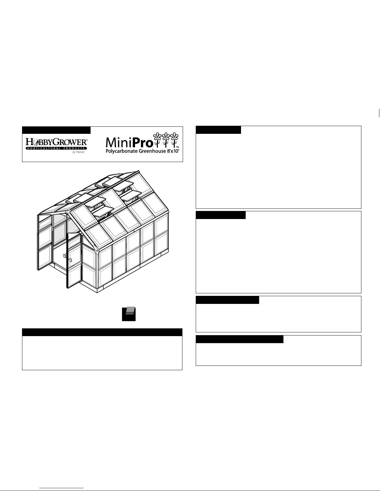
Overall Dimensions
(Apprimate; Including base)
120-7/8”
L • 99-1/4” W • 84.5/8” H
307
L • 252 W • 215 H cms
ASSEMBLY INSTRUCTIONS
PALRA M A MERI CAS
Horticultural Products Division
Formerly SPS International
MARLAP
Please read these instructions carefully before you start to assemble this greenhouse. To save time and
ensure proper assembly, follow the step-by-step instructions carefully in order. Assembly is easiest when
at least two people are present. Keep these instructions in a safe place for future reference.
An updated and/or improved version of this assembly guide may be available for download from the
HobbyGrower web site. Also, if you would like to view a brief general assembly video to gain a basic
understanding of how a HobbyGrower brand greenhouse is constructed, visit
http://www.hobbygrower.com, then click on the Assembly tab.
IMPORTANT!!!
TOOLS & EQUIPMENT REQUIRED
SAFETY ADVICE
GENERAL ADVICE
CARE & MAINTENANCE
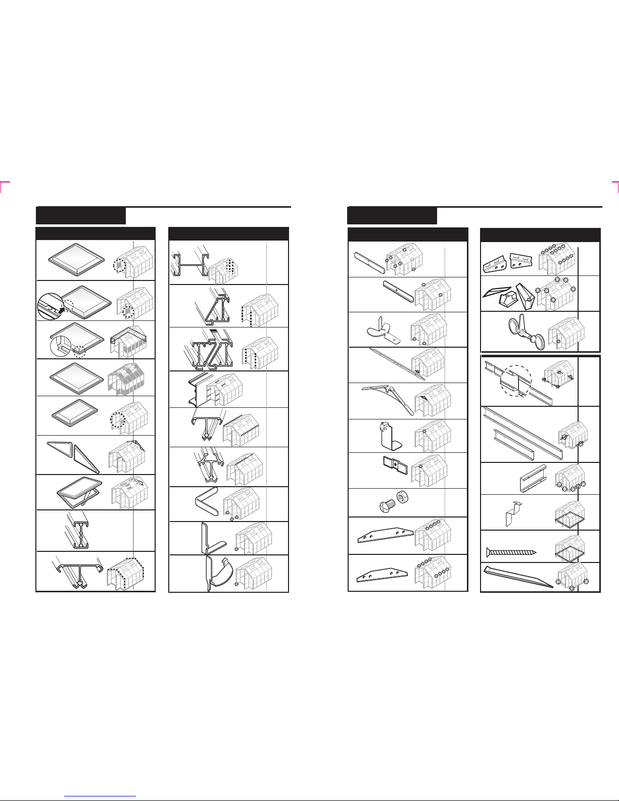
See next page for complete list of parts
• Do not attempt to assemble the greenhouse in
windy or wet conditions.
• Take special care not to touch overhead power
cables with aluminum profiles.
• Ensure that there are no buried pipes or cable in
the ground before inserting the ground stakes.
• Always wear shoes and saftey goggles during
assembly.
• We strongly recommend the use of work glove
during assembly as aluminum profiles may have
sharp edges.
• Dispose of plastic bags and protective poly film
covers safely - keep them out of reach of small
children.
• The greenhouse must be positioned and
anchored
on a flat, level surface.
• Do not lean on or push against the greenhouse
during construction.
• Keep children away from assembly area - many
parts may have sharp edges.
• Do not position your greenhouse in an area
exposed to heavy wind.
• Do not attempt to assemble the greenhouse if
your are tired, have taken drugs or alcohol or if
you are prone to dizzy spells.
• If you use a step ladder, carefully follow the
manufacturer's instructions.
• Hot items such as recently used grills,
blowtorches, etc. must not be stored in the
greenhouse.
• Before beginning the assembly process,
confirm that all necessary parts have been
included in the package. It is advisable to lay the
parts out in an orderly fashion according to the part
numbers so that parts can be easily identified
during the assembly process. If parts are missing,
contact SPS International at (800) 994-5626.
• This is a multi-part assembly. Allow at least 8 to
10 hours to assemble from start to finish. Do
not begin assembly if heavy winds or rains are
expected within 14 hours.
• Choose a sunny level location for your
greenhouse, away from overhanging trees.
• You can opt to anchor your greenhouse to a
concrete floor, or you can use the supplied anchor
kit to anchor to soil or turf. If you intend to anchor
your greenhouse directly to concrete, you must
purchase separately concrete anchor screws.
• It is advisable to use lubricant to ease the
connection between aluminum profiles and panel
(a mild soap and water solution is useful for this).
• We strongly advise that you keep the special
poly-film protective covers on the side panels and
the first row of roof panels until the greenhouse is
fully assembled. You should however remove the
poly-film prior to installing the very top roof panels.
Also, if the panels will be in the direct sun, the
protective film should be removed. Otherwise the
film may become irreversably bonded to the
polycarbonate panel.
• Keep roof clear of snow and leaves.
• Use mild soap and water and a soft cloth to wash
greenhouse glazing panels. Rinse with cold water.
• Do not use acetone, abrassive cleaners or
sponges, or other amonia-based cleaners to clean
the clear panels.
• Some chemicals and cleaners can be agressive to
the clear panels, which are made of
polycarbonate.
For a complete list of chemical
compatibility, visit:
http://www.spscorp.com/compatibility
• To purchase replacement parts, contact customer
service at SPS International at (800) 994-5626.
• 100% "Silicone" Sealant
(compatible w/polycarbonate)
• Tape measure
• Work gloves
• Plastic or rubber mallet
• Crosshead Screwdriver
(a.ka. "Philips")
• Lubricant (mild soap & water
solution works well)
• Scissors
• Step ladder
• Level
• Large Hammer (for anchor stakes)
• Drill and 5/64" drill bit
Page 2
ITEM MM QTY.
M19
2
M10d
6
120mm 9
M10
M9
3
A15
1290mm 2
700mm 2
A38
590mm 8
A40
1495mm 2
A14
325mm 2
1390mm 2
1435mm 1
600mm 1
P3
P4
P5
ITEM MM QTY.
2
P7
10
P6
ITEM MM QTY.
A39
A11
570mm 6
590mm 16
1230mm 2
1390mm 16
1495mm 4
650mm 2
A13
1390mm 8
CONTENTS CONTENTS
ITEM MM QTY.
M52
24L
24R
4
M45
C55
6
8
M46
10
16mm 66
A16
M29
P1
600x600mm 1
P2
600x600mm 1
600x700mm 16
4
4
M37
1
M22
12mm 49
40mm 6
M42
2
M43
M44
1
1
1
6
M56
16
600mm
600x700mm 34
330x600mm
1290mm 2
408mm 2
M601
1490mm 4
1
M48
1
M49
4
1200mm
M602
M603
2
M53
M604
1
M50
M606
2
Page 3
(a)
(b)
(b)
M601
M601
M606
M606
M601
M601
M603
(c)
(c)
click
(d)
M603
M604
M29
1
2
M604
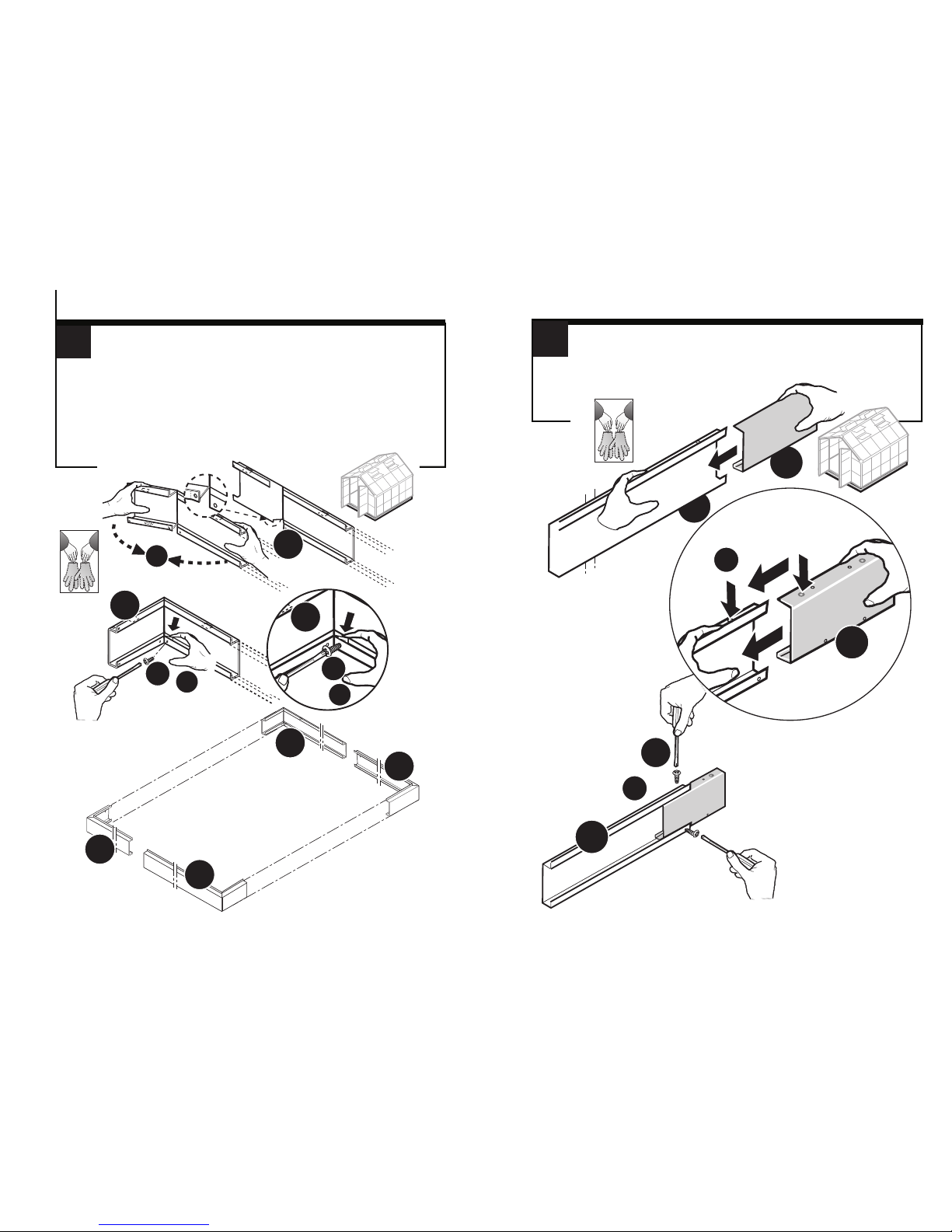
The short profiles M604 are to be used in the continuing assembly for
interconnecting all the rest base profiles (c).
When performing this next connections step , verify that the small
protruding convex metal in profile M604, engages the bore corresponnding
on all other base profiles - listen to hear the "click" (c) sound.
Assembling the Base
Start assembling the base of the greenhousewith the following prep aratory
step:
Observe the recess cut at the width of profile M601. Along this position,
bend the profile M601 to form a right angle (a).
NOTE - you must wear protective gloves for performing this operation.
ATTENTION - note that the small t ab cut in the lower side of the profile
has to remain inside the angle being formed.
When inserting screw M29 to fasten the formed angle (b), be sure to
have this tab flush with the inside flat lower surface of the profile.
Proceed to similarly bend , the other one supplied M601
profile and two profiles M606.
M601
M29
M29
Page 4
3
4a
M603
M606
(e)
(e)
M604
M604
M604
M602
M601
M606
M601
M601
M602
M602
M606
M603
4b2
M56
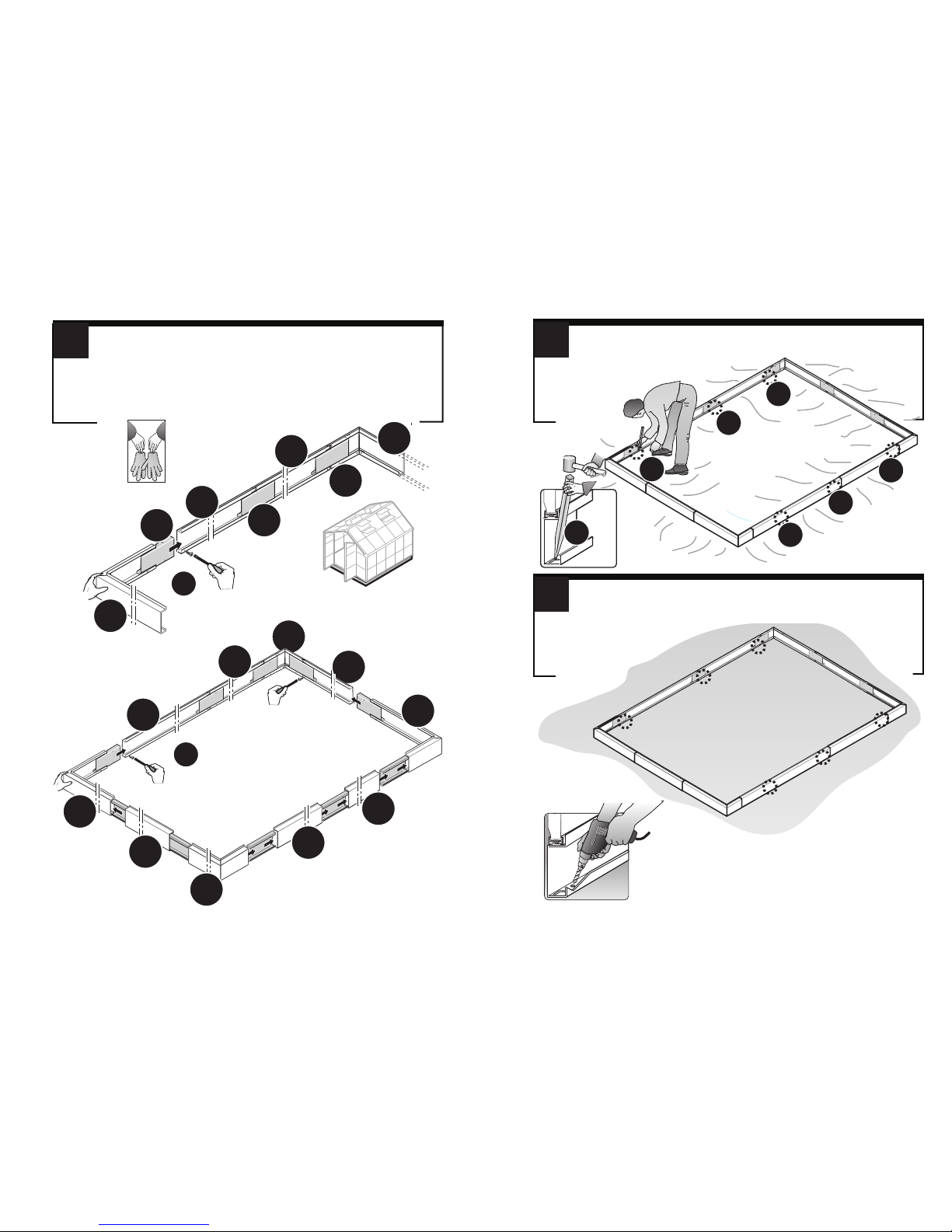
Lay the completed base in the position intended to be it s correct
site, and secure it to the ground using pegs M56
As shown in drawing 3, assemble the complete greenhouse
base using all base profiles (M601, M602, M603, M604, M606) as in
the drawing.
When the floor under the greenhouse does not permit hammering
the pegs into it (e. g., a concrete floor), use a drill to drill bores
in the concrete at the places where holes are ready in the profiles.
M56
M56
M56
M56
M56
M56
M602
M602
M602
Page 5
5
6
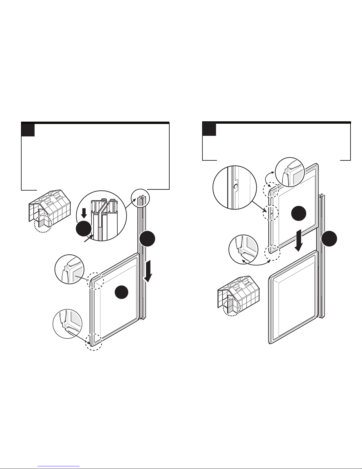
Door Assembly
Select profile A16/1290 mm
IMPORTANT!
You must ensure it is in up-right position.
Slide the profile unto a square panel P4.
When necessary use a lubricant to ease connection between
aluminum profiles and the panels.
Note that all panels have slots all around their edges. These
slots serve to affect the interlocking between the panels and
the aluminum profiles, where exist.
1
A16
1290
P4
A16
1290
1
A16
1290
P4
P2
Select the square panel P2 (with the p anel having the door
handle hole). slide it unto the profile. Be careful to have the
door handle hole on the left side (the opposing side to the
aluminum profile A16).
Do not slide it all the way down, as an aluminum profile has
to be inserted between it and the panel below it.
Door
side
Page 6
7
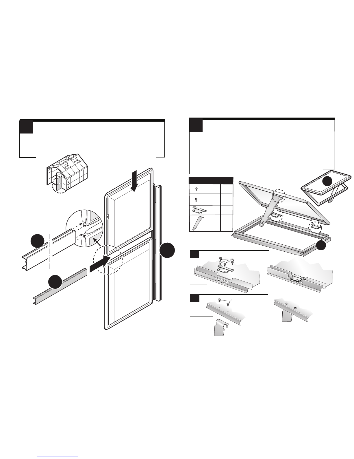
Take aluminum profile A38/590, with the flat rectangle side
facing you, and slide it between panels P4 and P2, as shown.
It is advisable to use a lubricant to ease connection between
profiles and panels.
P4
P2
A38
590
A38
590
A16
1290
8
8mm
14mm
(b)
(a)
P7
P7
(a)
(b)
(a)
We separately assemble now the window assembly (to be
mounted later on).
This is done in two stages, (a) and (b), respectively, where all
the items are supplied in the “window kit”.
(a) Installing the hinges. Insert the 8 mm screws into the hinges
– IMPORT ANT – use the screws provided by the factory – found
in the “window kit”.
(b) Install the spacer (used to support the widow in the open
position) – using the 14 mm screws (also provided in the kit).
NOTE – it is advisable to assemble all the 10 “window assembly”
units at this stage.
ITEM QTY .
8mm
14mm
8
2
2
1
Page 7
10
P4
P2
P4
P3
A16
1290
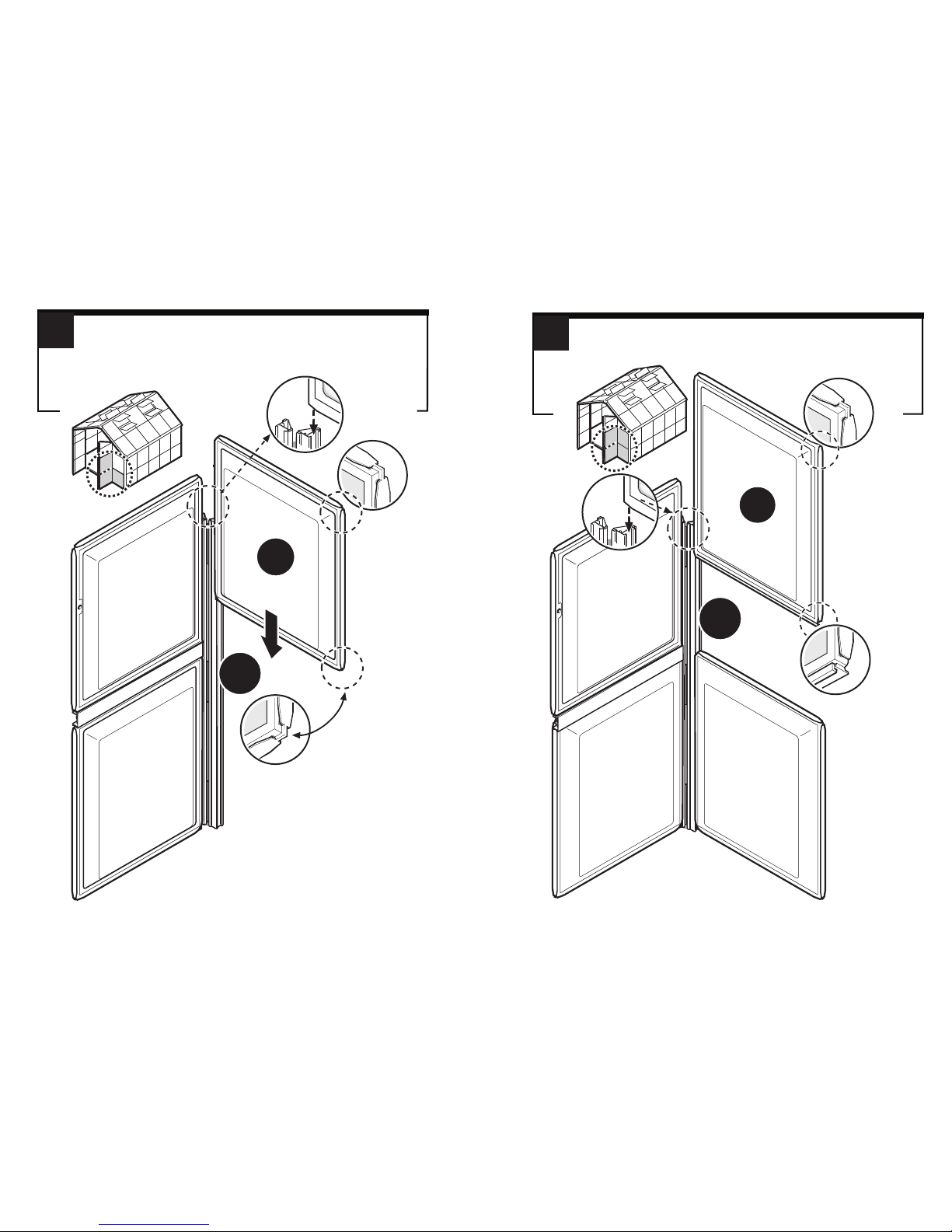
Take panel P3 (be sure to position it so that the longer edge is
vertical), having the assigned slot (see inset) at the bottom.
Do not slide it all the way down.
9
1
P4
P21P2
P4
Take another panel P4 and thread it onto the free edge of
aluminum profile A16/1290.
Ensure that you slide it all the way down.
A16
1290
Page 8
12
P4
P2
P4
P3
A13
1390
A13
1390
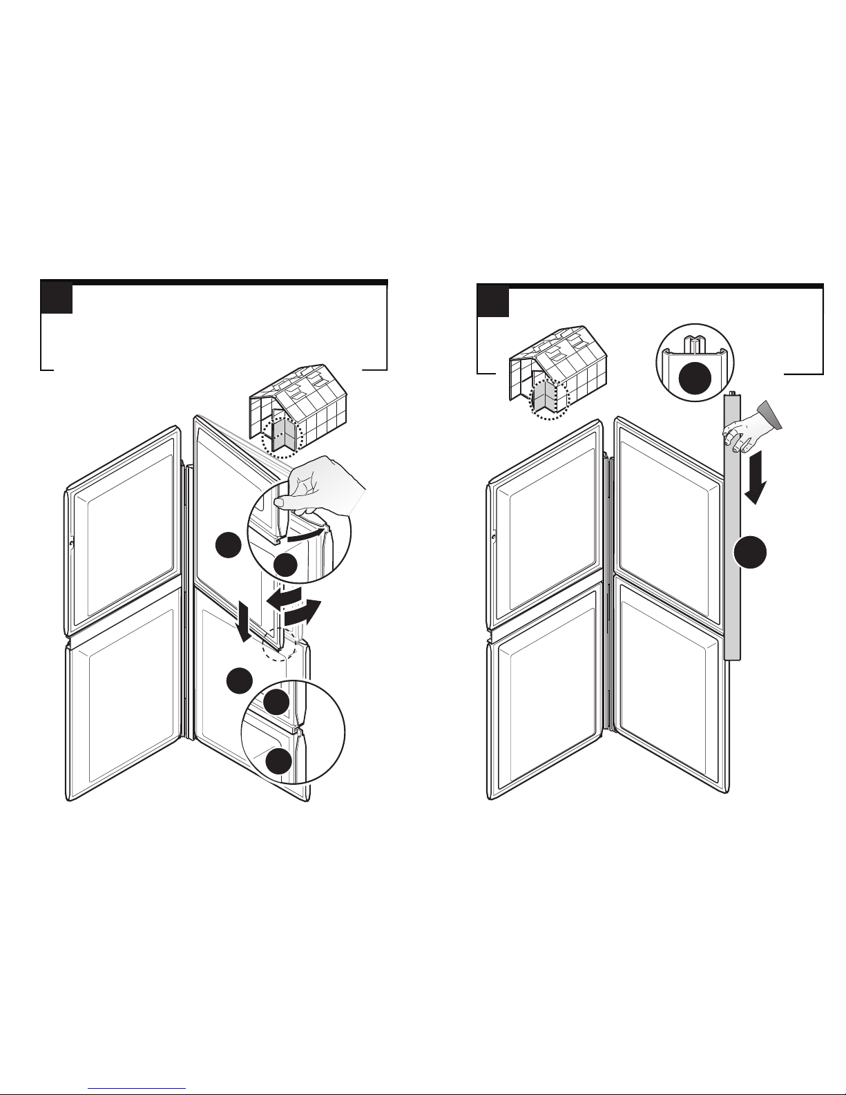
Take aluminum profile A13/1390, and slide it all the way down
along the matching slots on P3 and P4 but leave approximately 50mm
protruding at the top. The reason for this will become.
11
To interlock the two panels, follow the steps below (as shown):
(a) – pull the free edge of panel P3 towards you.
(b) – Carefully slide the panel down, until it touches P4 - the
lower panel.
(c) – Push it back - align it along P4, ensuring that the
dedicated slot (on P3) interlocks securely into the matching
place in P4.
P4
P2
P4
(b)
P3
(a)
(c)
P3
P3
(c)
P4
Page 9
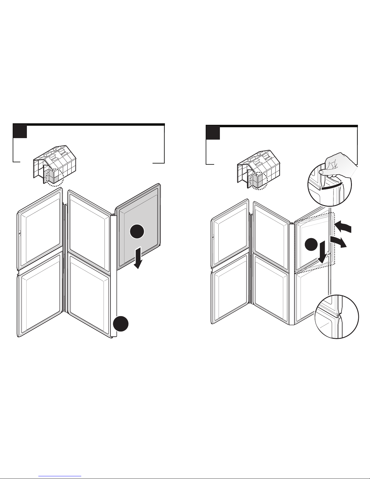
14
P3
P4
P3
P4
(b)
(a)
(c)
(c)
P3
P4
P4
P2
Take now one more P3 panel, and interlock it on top of P4,
employing the same method you used in step 10.
13
P4
P3
A13
1390
P4
P2
P4
Slide a new panel P4, all the way down along aluminum profile
A13/1390. Note that it forms a 90o angle with the preceding P4
panel.
Page 10
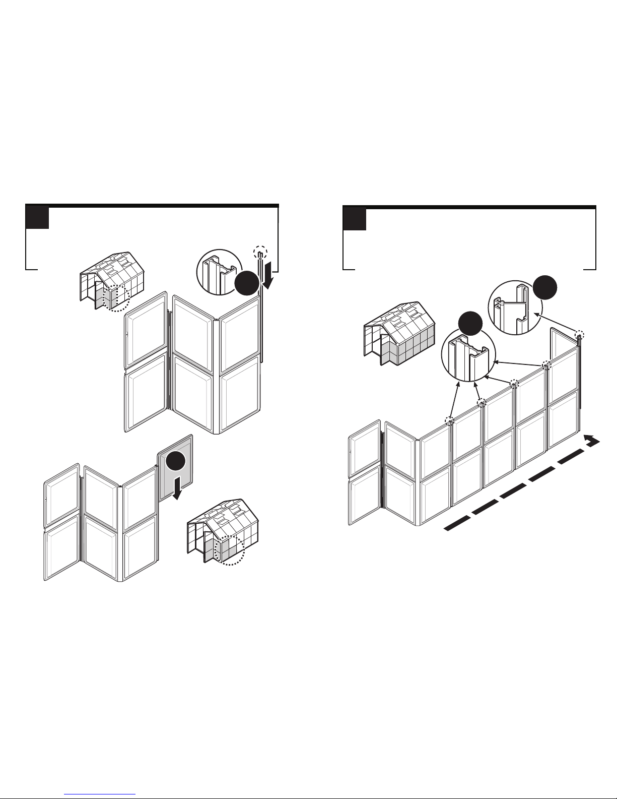
P4
P3
BACK
A13
1390
A11
1390
P3
P4
P3
P4
P3
P4
P3
IMPORTANT!
Assemble in this
direction
P4
P3
P4
P3
P4
P2
16
Slide two more panels P4 and P3 (P4 first, P3 on it) – continue
to add such P3 & P4 couples, interconnected by aluminum
profile A11/1390, until you complete to construct a wall of five
such couples. At the extreme end, form a right angle corner
interlocking an aluminum profile A13/1390. Continue now( in
the 90o direction) by interlocking a P3 – P4 couple once more.
15
P4
P3
P4
P3
P4
P2
P4
P4
P3
P4
P3
A11
1390
P4
P2
Take now a double sided interlocking aluminum profile
A11/1390 and slide it all the way down along the free vertical
edges of P3 and P4 but leave approximately 50mm
protruding at the top. The reason for this will become.
Page 11
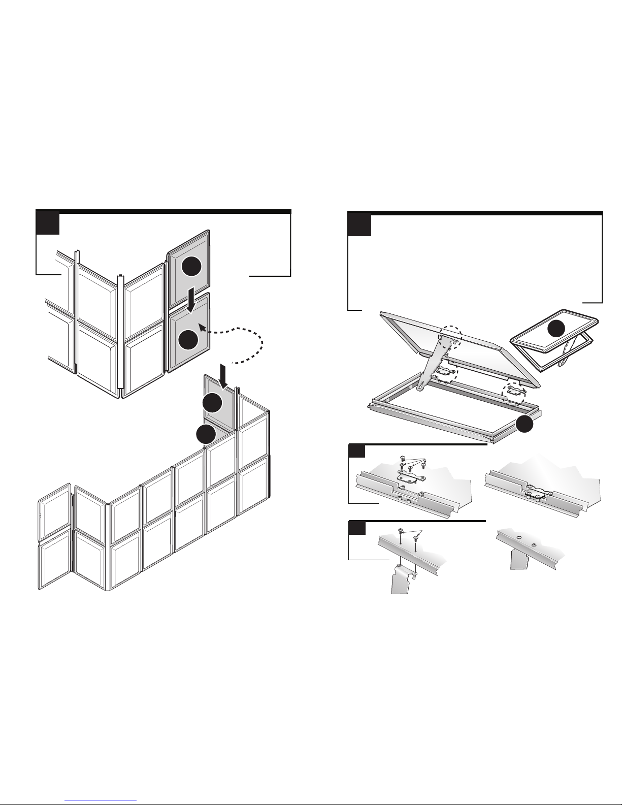
17
18
P4
P4
P4
P3
P3
P3
BACK
P3
P4
P4
P3
P4
P3
P4
P3
P4
P3
P4
P3
P4
P3
P4
P3
P4
P3
P4
P2
8mm
14mm
(a)
(b)
P7
P7
(a)
(b)
(a)
Add one additional P3 – P4 couple (P4 the lower one).
We separately assemble now the vent assembly (to be
mounted later on).
This is done in two stages, (a) and (b), respectively, where all
the items are supplied in the “vent kit”.
(a) Installing the hinges. Insert the 8 mm screws into the hinges
– IMPORT ANT – use the screws provided by the factory – found
in the “vent kit”.
(b) Install the spacer (used to support the vent in the open
position) – using the 14 mm screws (also provided in the kit).
NOTE – it is advisable to assemble all the 10 “vent assembly”
units at this stage.
Page 12
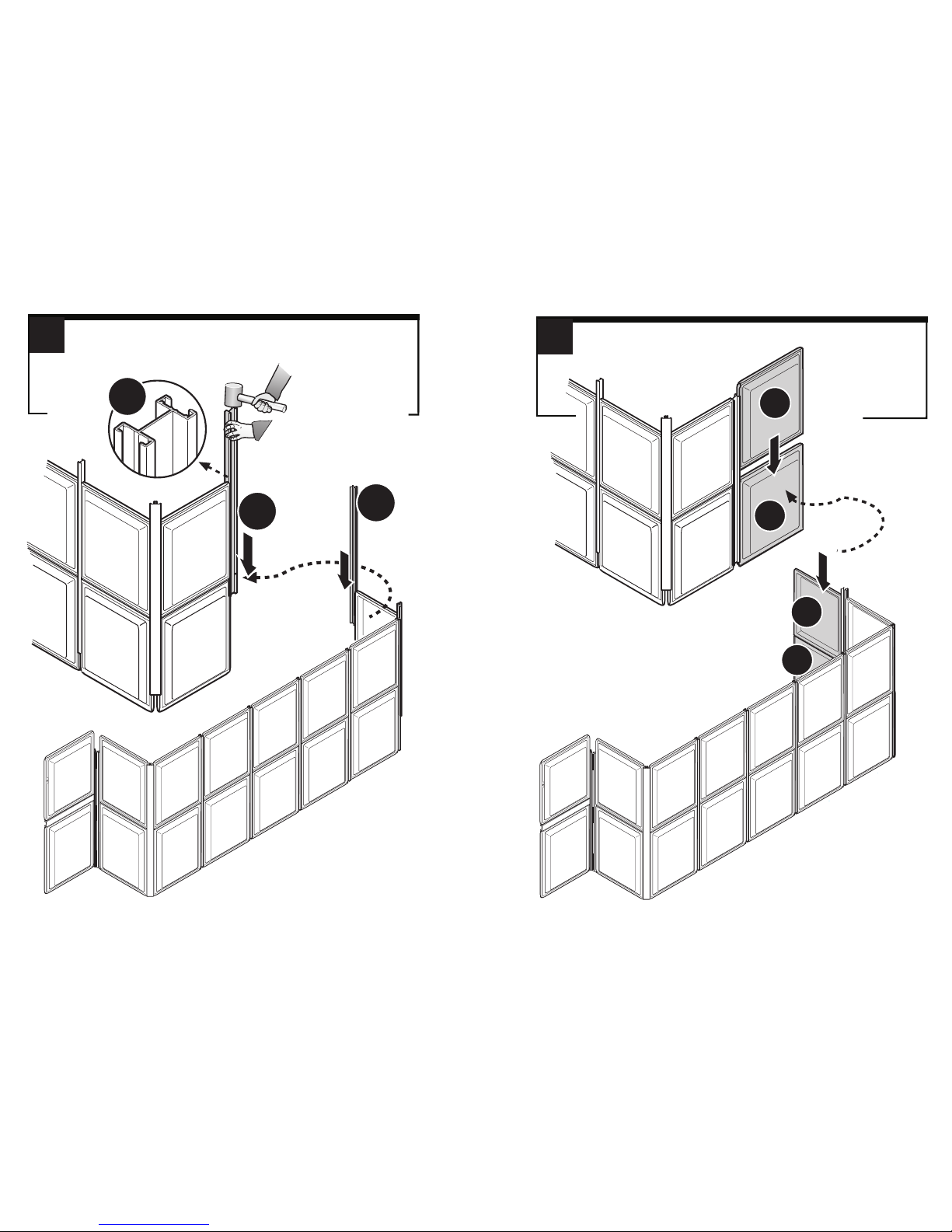
18
P4
P4
P4
P3
P3
P3
BACK
P3
P4
P4
P3
P4
P3
P4
P3
P4
P3
P4
P3
P4
P3
P4
P3
P4
P3
P4
P2
Add one additional P3 – P4 couple (P4 the lower one).
17
A14
1390
P4
P4
P4
P3
P3
P3
A14
1390
P4
P3
P3
P4
P3
P4
P3
P4
P3
P4
P3
P4
P3
BACK
P4
P2
A14
1390
We continue now the construction of the Greenhouse’ s rear wall.
Slide now an aluminum profile A14/1390 along the free edge of
the P3 – P4 couple (as shown by the arrows).
Page 13
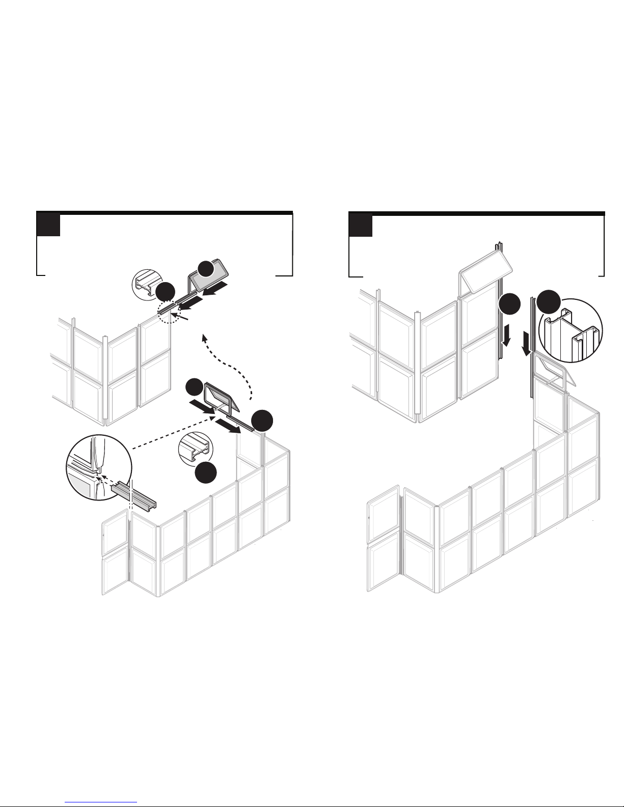
16
19
20
P4
A11
590
(a)
(b)
P7
A11
590
A14
1435
A14
1435
P4
P4
P3
P4
P4
P4
P3
P3
P3
(a)
(b)
A11
590
P7
Slide an aluminum profile A11-590 from right to left onto the upper
edge of the panel P3, (a) in the drawing. Now slide the
vent assembly P7 (also from right to left). ATTENTION ensure that the window’s flap opens outwards (up).
Verify that P3. P4 and P7 are perfectly aligned one above the
other. Slide aluminum profile A14/1435 all the way down to the
bottom of P4.
P3
P4
P7
Page 14
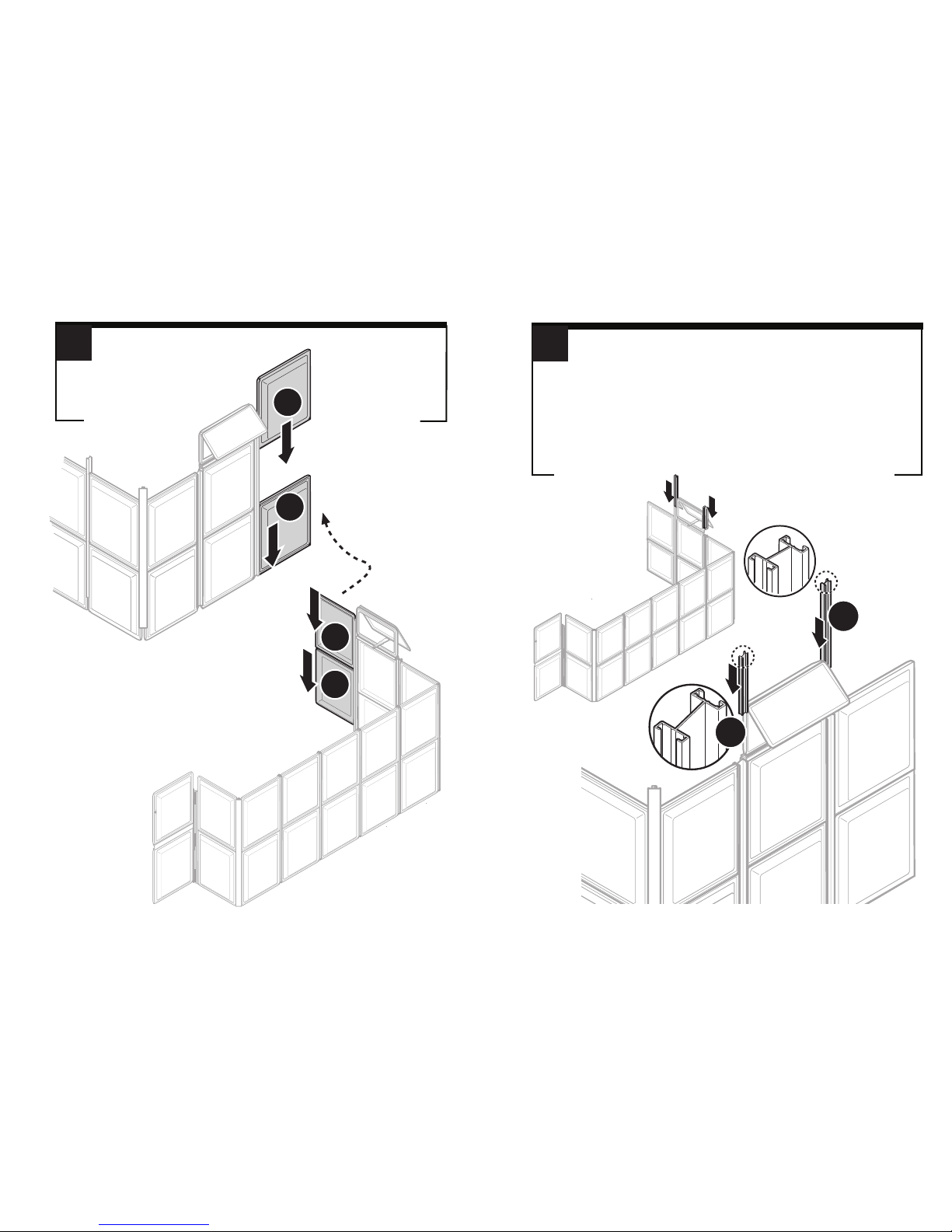
21
22
(a)
(b)
P4
P3
P4
P4
P3
P4
P4
P4
P3
P3
P3
(b)
(a)
P3
P4
P7
Continue by adding one more P3 – P4 couple.
On the two flanks of the vent (see arrows in
drawing), slide two different aluminum profiles, namely profile
A14/325 on your left and profile A14/600 on your right (as clearly
shown in the drawing), until they are positioned at the top of the
existing aluminum profiles below them.
IMPORTANT – Note that the top of aluminum profile A14/325
is slanted. When installing it in the structure, take care to have
the lower top point positioned on the left (as you see it, namely
towards the completed side wall of the structure).
P4
P3
P4
P3
P3
P7
P3
P4
A14
600
A14
325
P7
Page 15
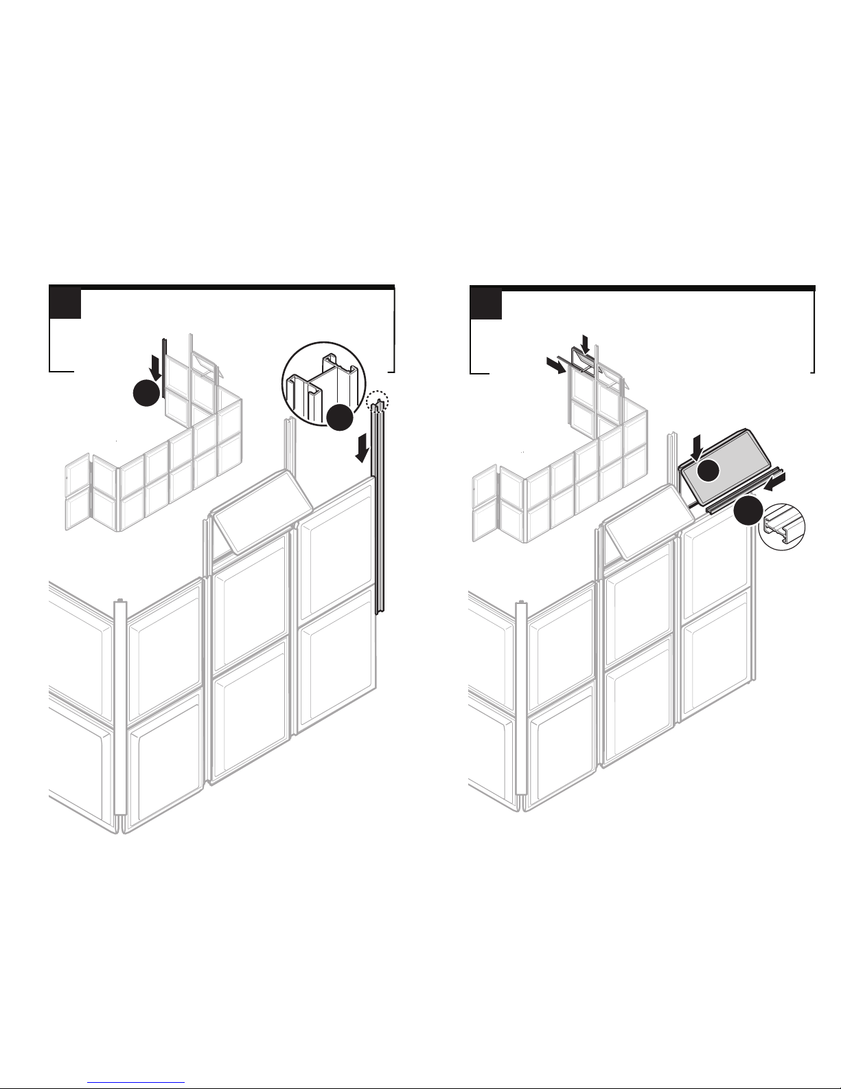
23
24
(b)
P4
P3
P4
P4
P3
P3
P7
P3
P4
(a)
P7
A11
590
Mounting the Second vent. (a) First, slide down P7 unit
(vent) down the A14/600 profile. Do not push it all the way
down. In the formed gap, slide A11/590.
At the free edge of the structure (panels P3 & P4) insert
interconnecting aluminum profile A14/1390, pushing it all the
way down.
P4
P3
P4
P4
P3
P3
P7
P3
P4
A14
1390
A14
1390
(a)
(b)
Page 16
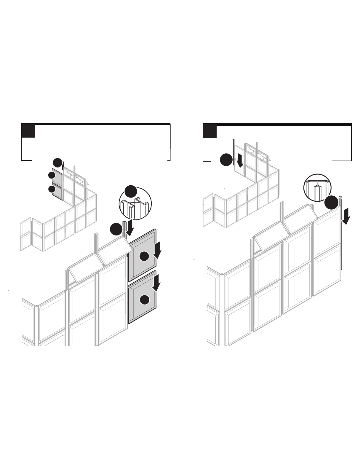
25
26
P4
P3
P4
P4
P3
P3
P7
P3
P4
P7
P3
P4
A13
1390
Interlock panels P4 and P3 to the right (free edge) of the existing
structure, (a) and (b) respectively . Now, (c): on the right (as you
see) of the second vent, slide panel A14/325. Note that here
position it so that the lower top point of the slanted edge should
be on the right.
Slide the corner building aluminum profile A13/1390 at the
free edge, as shown.
A14
325
P4
P3
P4
P4
P3
P3
P7
P3
P4
P3
(b)
P4
(a)
(c)
P7
A14
325
P3
P4
A14
325
A13
1390
Page 17
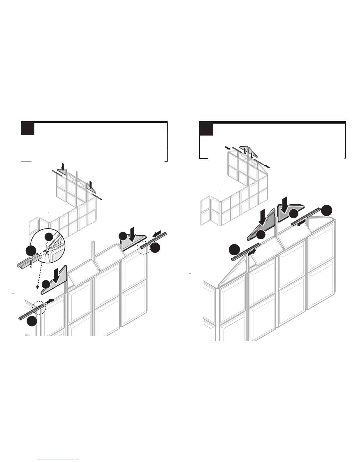
27
28
Now, that the rear wall is nearly completed, mount the triangular
panels P6 (matching the roof support structure).
This is a two stages step. First, slide the outer ones (a) (note
directions in the drawing) to interlock with aluminum profiles
A14/325, not all the way down. (b) Slide profiles A11/570 in the
space you formed, from left to right (left side) and from right to
left (right side).
Repeat the operation (similar steps) with the inner triangles
P6, executing the same (a) and (b) operations as in step 27.
(b)
(b)
(a)
(a)
(b)
P6
(a)
(a)
P3
P3
P7
P3
P4
P7
P3
P4
A11
570
A11
570
P6
(b)
A11
570
(a)
P4
P3
P4
P4
P3
P3
P7
P3
P4
P7
P3
P4
P6
P6
P6
A11
570
(a)
P6
(b)
(b)
A11
570
(b)
(a)
(a)
(b)
P6
(b)
Page 18
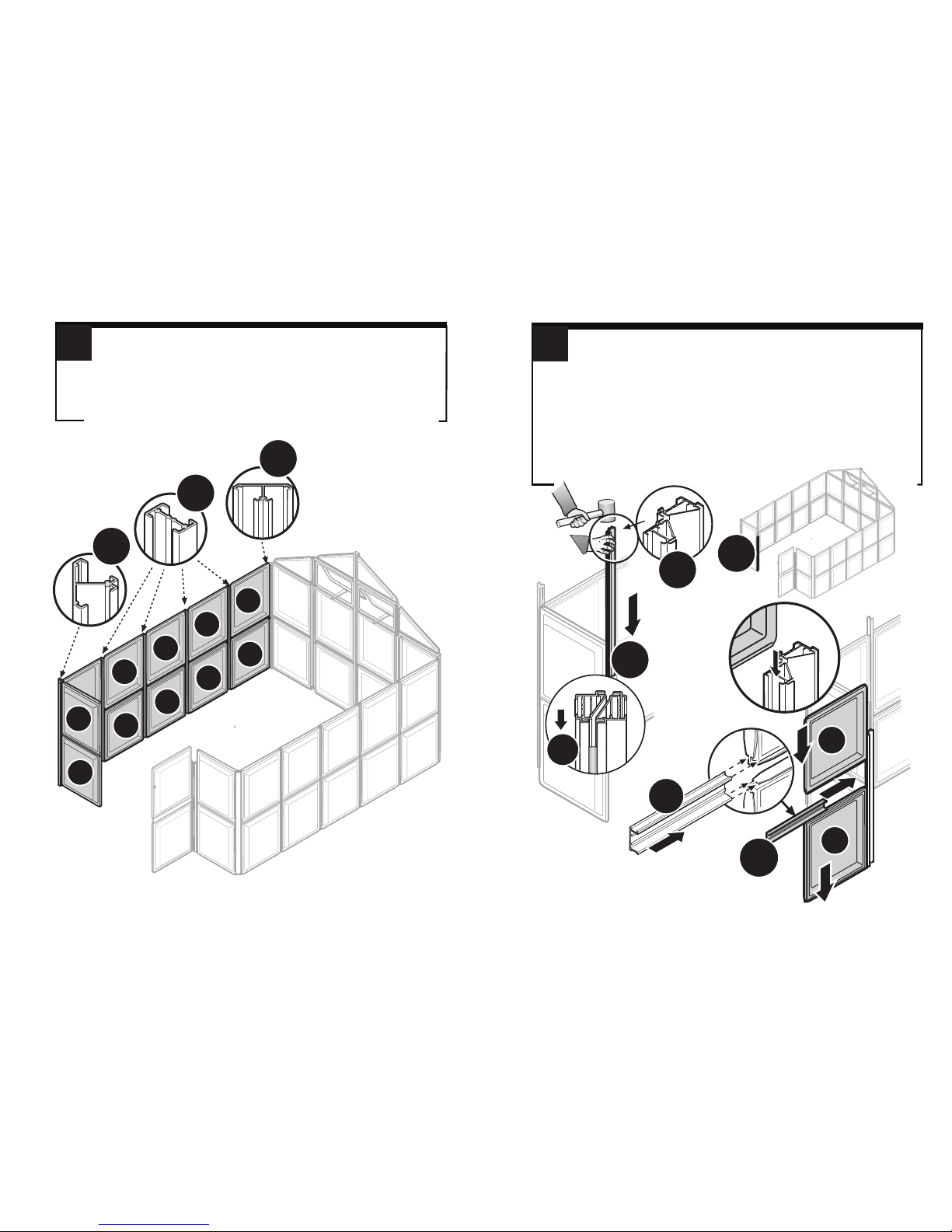
29
30
Continue by forming the other side wall: interlock a P4 – P3
panels couple, followed by sliding an aluminum profile A11/1390,
continuing as in step 15 until you complete construction of wall
of five such couples. At the extreme end, form a right angle corner
interlocking an aluminum profile A13/1390. Continue now (at the
90o direction – we are at the front now) by interlocking once more
a P3 – P4 couple.
(a) Slide aluminum profile A16/1290 downwards. Pay attention
to mount it in the correct direction, so that after interlocking
the door panels (P4, P1) on it, the door would open outwards.
(b) Slide panel P4 all the way down interlocking with profile (a).
(c) Slide the rectangular panel P1 unto the profile. Do not slide
it all the way down, as an aluminum profile has to be inserted
between it and panel P4 below it.
(d) Take aluminum profile A38/590, with the flat rectangle side
facing you, and slide it between panels P4 and P1, as shown.
It is advisable to use a lubricant to ease connection between
profiles and panels.
P3
P4
P3
P4
P3
P4
P3
P4
P3
P4
A13
1390
A13
1390
A11
1390
A38
590
A38
590
(b)
(c)
(d)
P1
P4
P4
P3
A16
1290
(a)
A16
1290
A16
1290
(b)
A16
1290
Door
side
Page 19
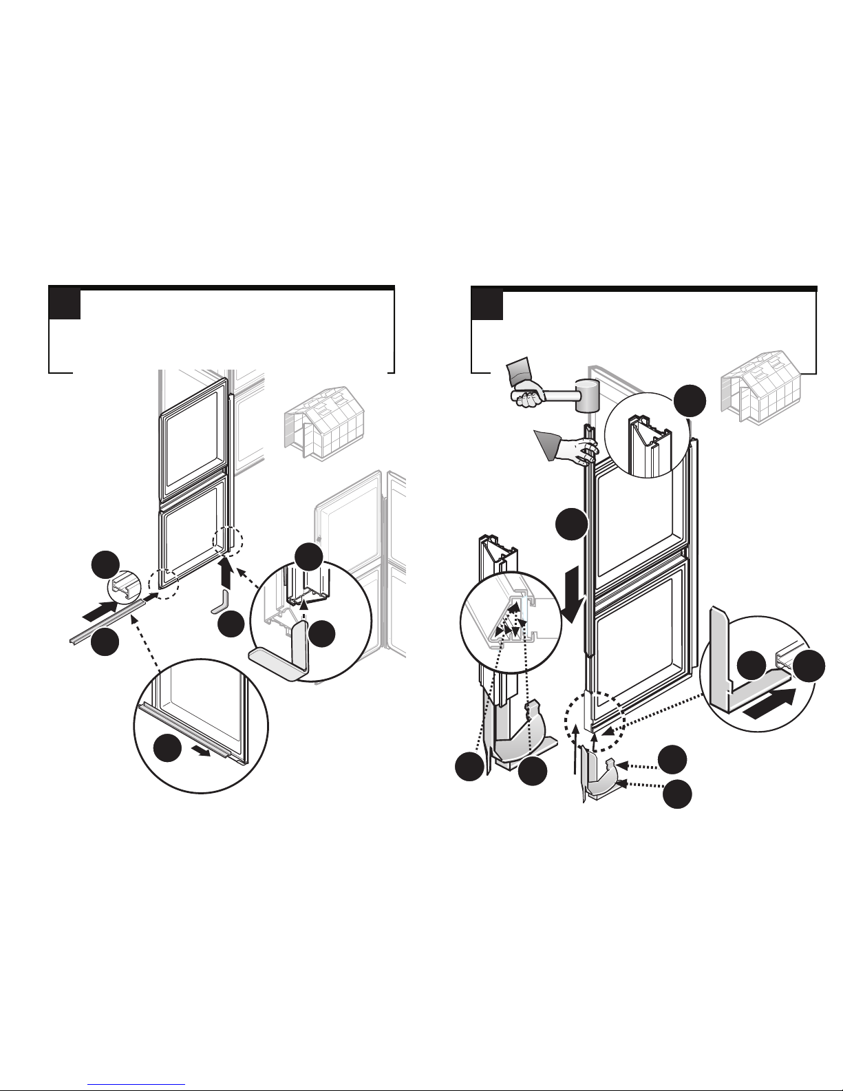
32
M9
A11
590
(a)
(b)
M9
(a)
A16
1290
A11
590
(b)
By the following four steps, we apply a protection structure to
the bottom of the left door. (a) Take angle bar M9, slide unto
aluminum profile A16/1290 until it latches into the groove at the
bottom of panel A16. (b) Slide aluminum profile A11/590 from
the other end until it encompasses angle bar M9.
31
A11
590
Insert right angle corner M37 (a).into aluminum profile A11/590
(at the bottom of the door).
Continue by attaching flush with it door stop M48 (b), slide profile
A15/1290 downwards all the way until door stops M48 engages
them (c).
(a)
A15
1290
A15
1290
(c)
(c)
(b)
M37
A11
590
M37
M37
M48
M37
M48
Page 20
(b)
M9
(a)
A11
590
(a)
M9
M9
A16
1290
33
M9
(b)
A15
1290
(b)
M9
(c)
(a)
(a)
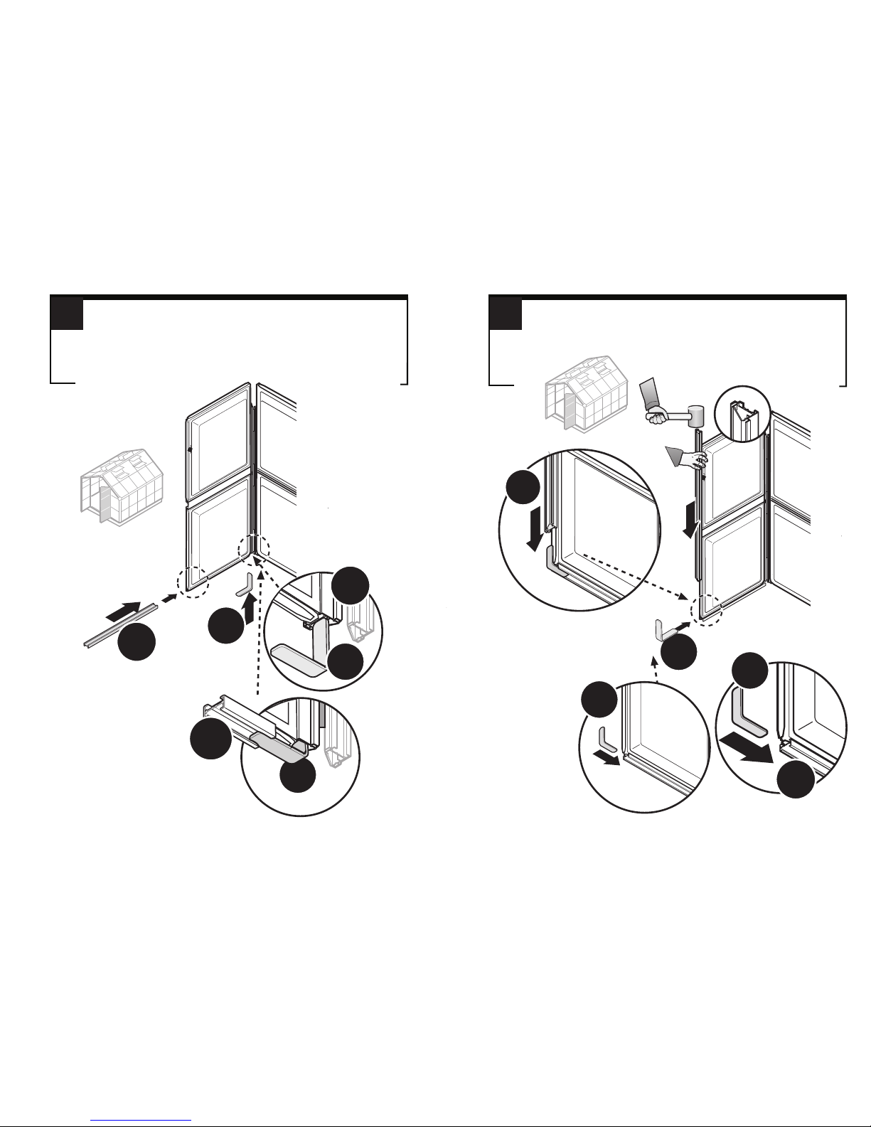
34
(a)
Complete the assembly and strengthening of the other door base
(right hand side one) following the same step s as before, namely:
insert right angle M9 into the door axis profile A16/1290 (a); slide
profile A11/590 into the door's bottom base panel (b)
simultaneously engaging it with M9.
Proceed with the operations strengthening the other door's base:
insert right angle M9 into the door axis profile A11/590 (a); slide
profile A15/1290 along the doors outer flank (on the panels left
side) until it engages the vertical part of right angle M9 (b).
A11
590
M9
(b)
A11
590
Page 21
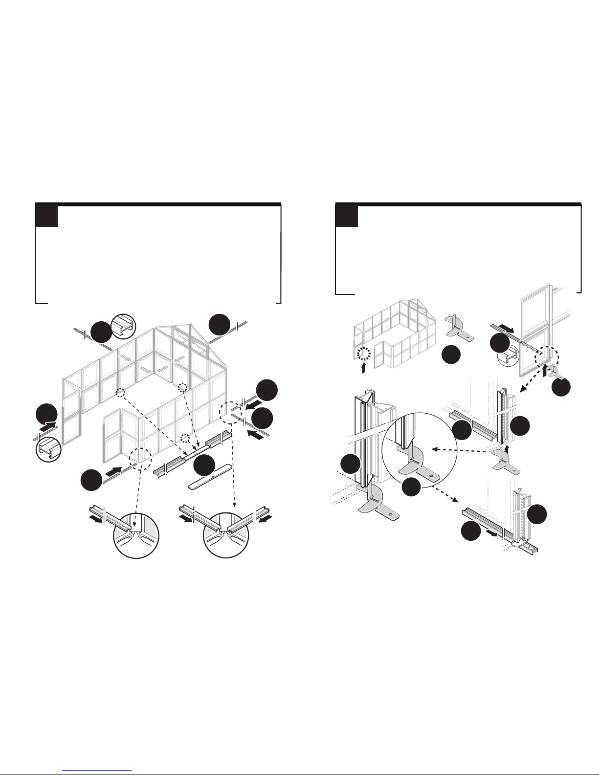
35 36
Proceed now to form a peripheral strengthening “belt” at the
bottom of the structure (excluding the front side bottom, (explained
later). For this end you will require the assistance of another
person. You will have to lift the greenhouse and slide six bottom
rail profiles A11’s (various sizes). Due to the variation in sizes,
follow the assembling exactly vis a vis observing the lengths
shown in the drawing. After all the bottom profiles are fitted, tap
down all the vertical profiles using a rubber mallet. The vertical
profiles A11 should sit on the bottom rail profiles and the corner
profiles A13’s sit on the floor.
Between every two adjacent A11’s, a bridging connector M10/120
is inserted.
A11
1495
A11
1495
M10
120
A11
1230
A11
1495
A11
1230
A11
1495
An aluminum profile A11/650 is now applied to the left half of
the front base. Half its length will be interlocked with the extreme
left panel P4, while the other half remains unconnected under
the door space.
(a) Insert M42 into the matching slot at the bottom of the door’s
axis – note the correct direction, as shown in the drawing: the
tab of M42 should be on the outer side of the structure..
(b) A11 passes through M42 as shown.
(b)
A11
650
A16
1290
OUTSIDE
INSIDE
(a)
A11
650
A16
1290
A11
650
(a)
(b)
M42
DOOR
M42
(a)
A16
1290
M42
INSIDE
Page 22
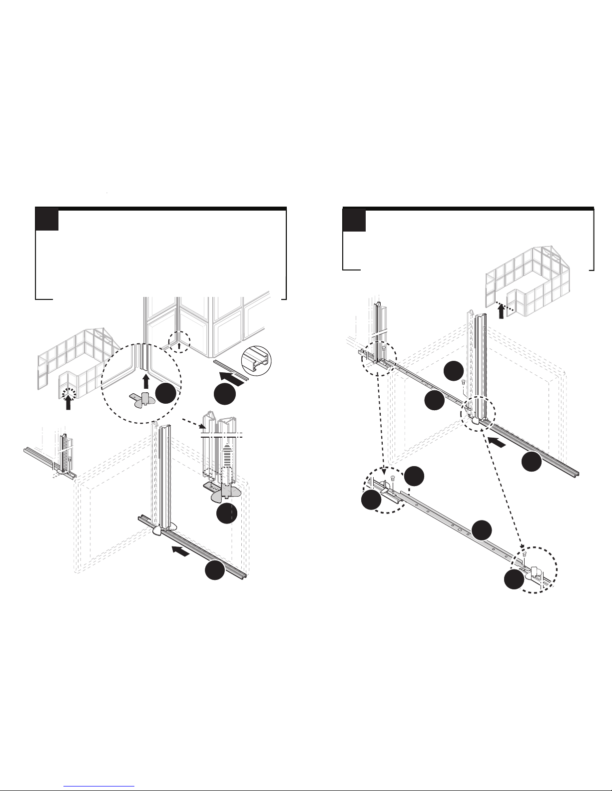
38
A11
650
OUTSIDE
INSIDE
M43
M42
INSIDE
(b)
A11
650
OUTSIDE
(a)
(b)
(a)
M42
A11
650
DOOR
OUTSIDE
INSIDE
INSIDE
OUTSIDE
The same process as in step 36 above (but with directions
reversed) is used to form the right hand half of the bottom base,
for right hand side door and adjacent panel P4.
Be sure to note correct directions. Follow steps (a) and (b)
as above. NOTE part M42 is the item inserted from below in
the (right) door axis.
Profile A11/650 enters all the way from the right to interlock
with door stopper M43.
Fasten, temporarily, the two screws on M43 on A11. Later on
(step 40), you should move M43 and tighten it at the correct
location for the door’s securing shaft M48
37
Take metal profile M43 and mount on both its side item M42,
secure it using screws M29.
Note - position M43 so that the right angle faces outwards,
namely the vertical part of M43 is on the inside of the structure
(as shown in the drawing).
M29
M42
M43
M42
M29
Page 23
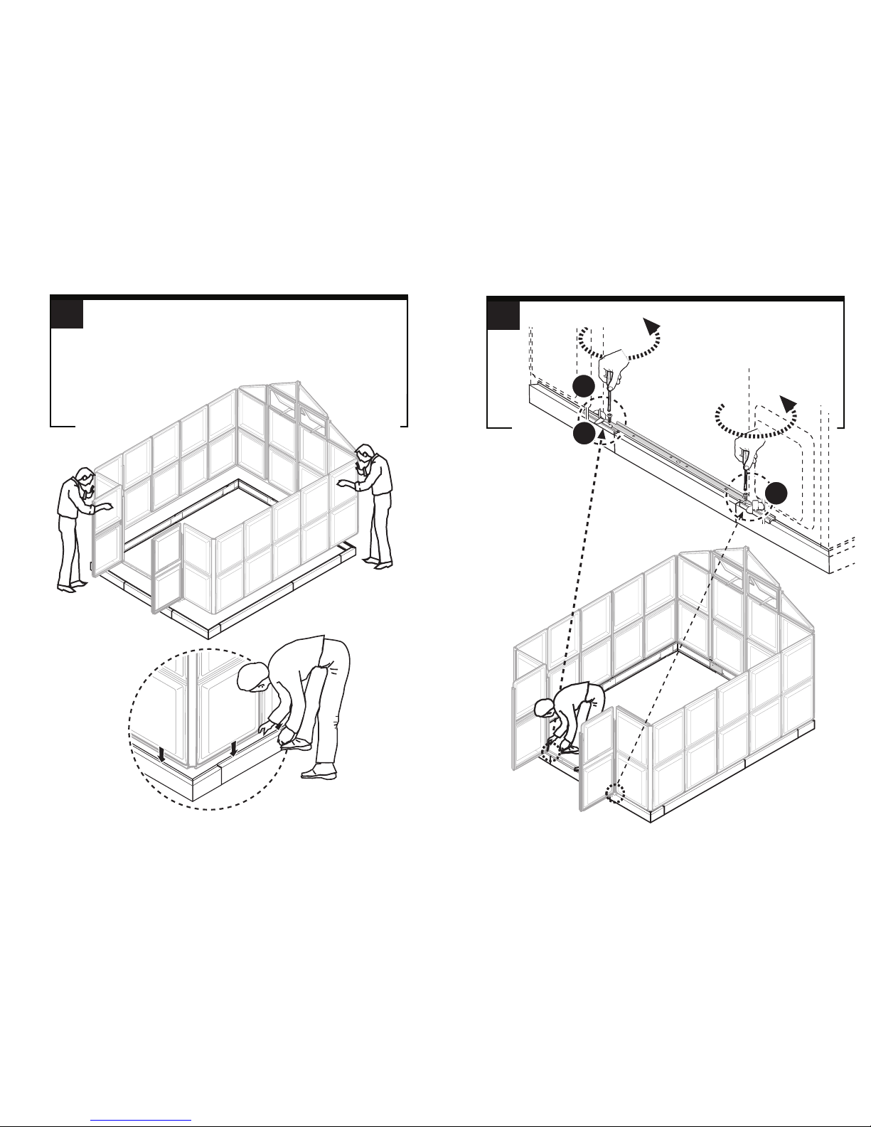
39
M29
40
Have two or three persons to carefully lift up the assembled
greenhouse structure and lay it accurately on the fixed down
base.
M42
M42
In order to secure the structure unto the base, partially release
screw M29.
Page 24
M29
M29
42
41
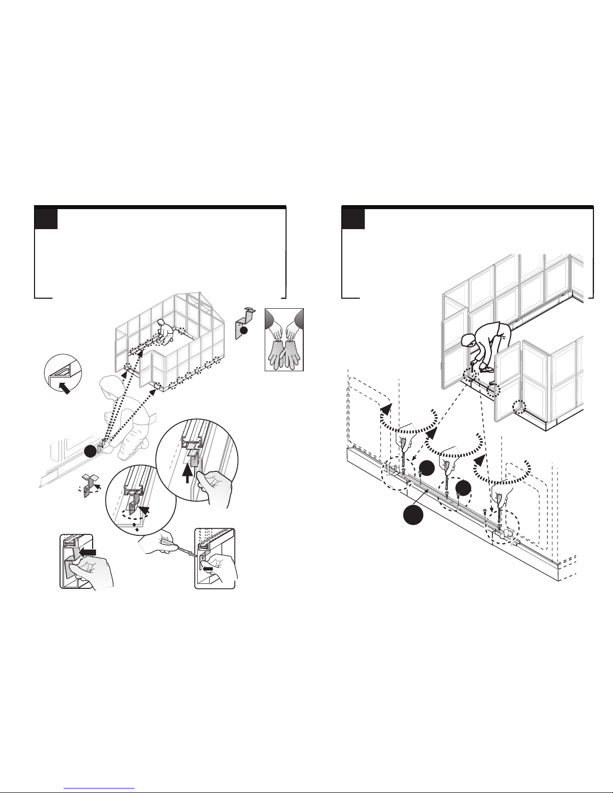
Tighten as much as necessary screws M29 (which were partially
loosened - step 40) all along the metal part M43. At
both ends of M43 part the screws go through M42 and
continue to the base. At the rest of M43 part (additional
holes), the screws are screwed directly unto the base frame.
M53
M53
M43
M53
M53
29
(a)
(c)
(d )
(b)
Connect the greenhouse structure to the base using part M53.
Please follow these steps: (a) & (b) Insert part M53 through the
openings in the metal base and push it into the aluminum profile 11.
(c) Turn part M53 90º, make sure to secure both sides of the
aluminum profile. (d) Secure (from the outside) part M53 usingscrew 29.
You may need someone to help you with this step( one person inside,
another person outside )
Page 25
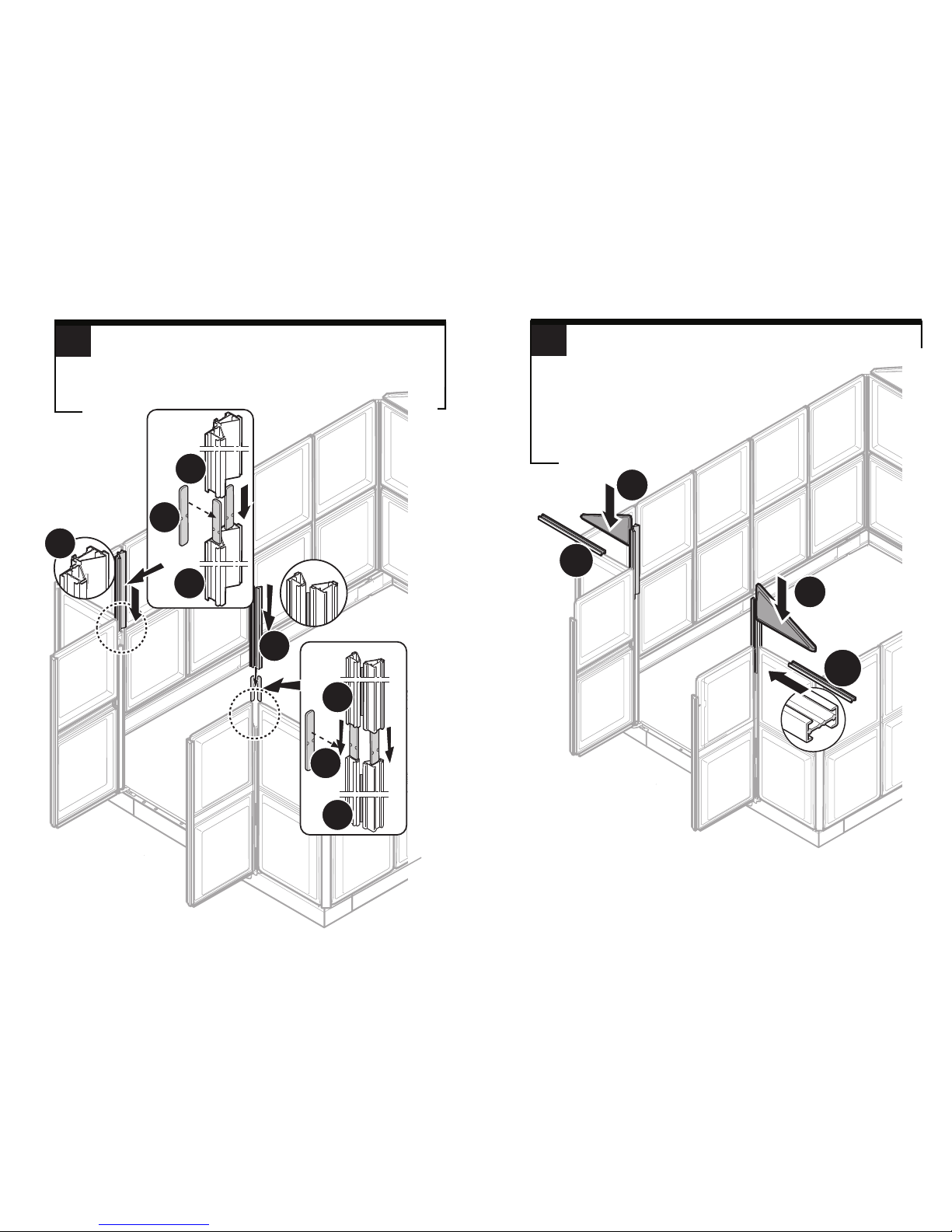
A16
408
A16
408
M10
120
A16
1290
A16
408
M10
120
A16
1290
A16
408
Tops of Doors
Extend upwards the axis A16/1290 of the two doors (left and
right), by first inserting profiles (one each) M10/120 into top of
profiles A16/1290 (in both of its two vertical members). Proceed
by inserting profile A16/408 into M10/120 concurrently with sliding
along top panels of the doors.
INSIDE
OUTSIDE
43
44
A11
570
P6
P6
A11
570
Assemble triangle panels P6 into profile A16/408 with the aid
of A11/570.
Page 26
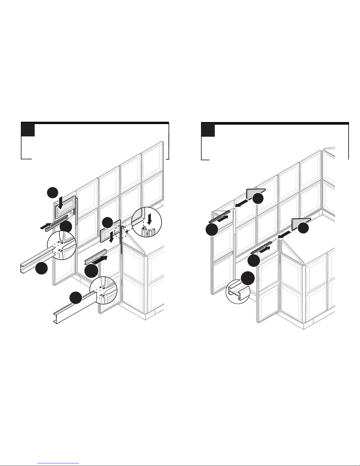
P6
(b)
(b)
P5
(a)
P5
(a)
A38
590
A38
590
A38
590
A38
590
Extending the Doors Upwards
Take panel P5 and profile A38/590, and install them exactly as
done in step 7.
45
(a)
A11
590
(b)
P6
A11
590
(b)
P6
(a)
A11
590
Using profile A11/590, mount triangle panel P6 on top of panel
P5.
46
Page 27
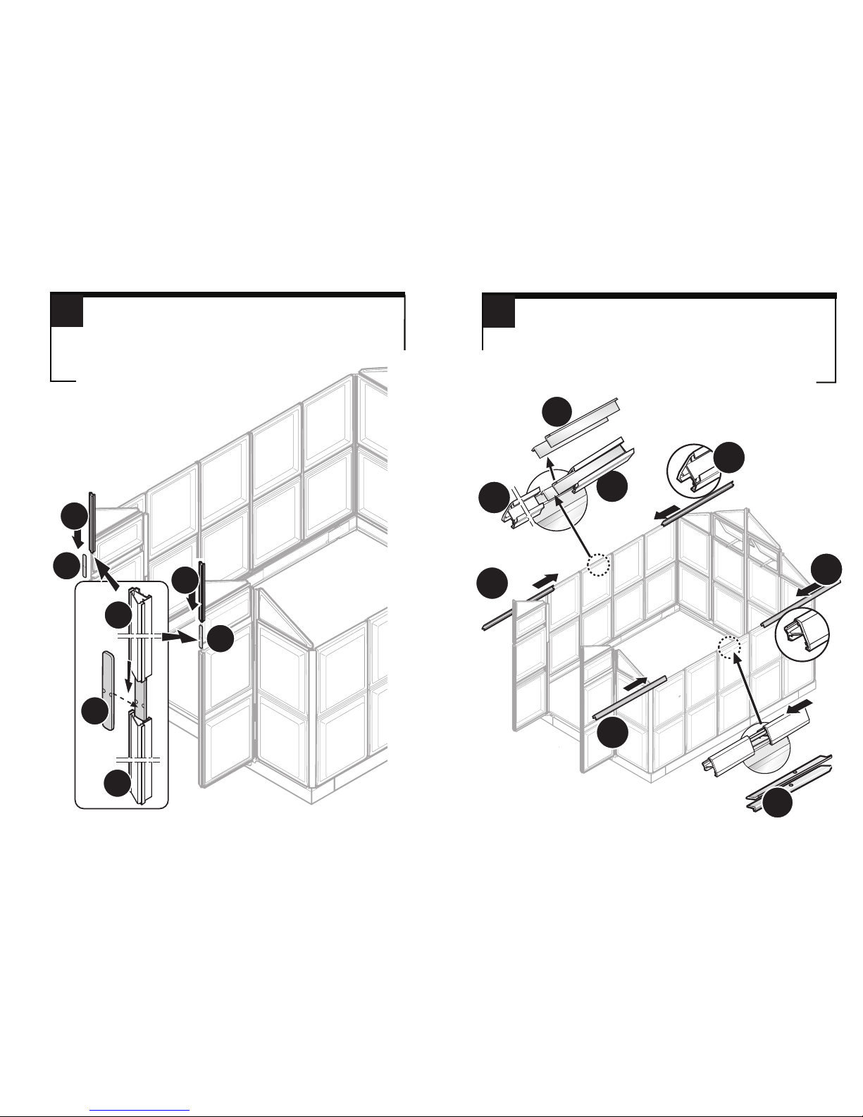
47
48
M10
120
M10
120
M10
120
A15
700
A15
700
A15
700
A15
1290
Insert bridging connector M10/120 into A15/1290. Extend profile
A15/1290 (with the protruding bridging connector) upwards by
interlocking it with profile A15/700, while threading A15/700
through panels P5 and P6.
Roof Assembly
Slide two profiles A39/1490 along the two sides (a) of the
greenhouse. Insert a joining bar M10D between each pair to
strengthen the join (b).
Panels may need aligning as you perform this step.
A39
1490
A39
1490
(a)
(a)
A39
1490
(a)
A39
1490
(a)
A39
1490
(b)
(b)
A39
1490
M10D
(b)
M10D
Page 28
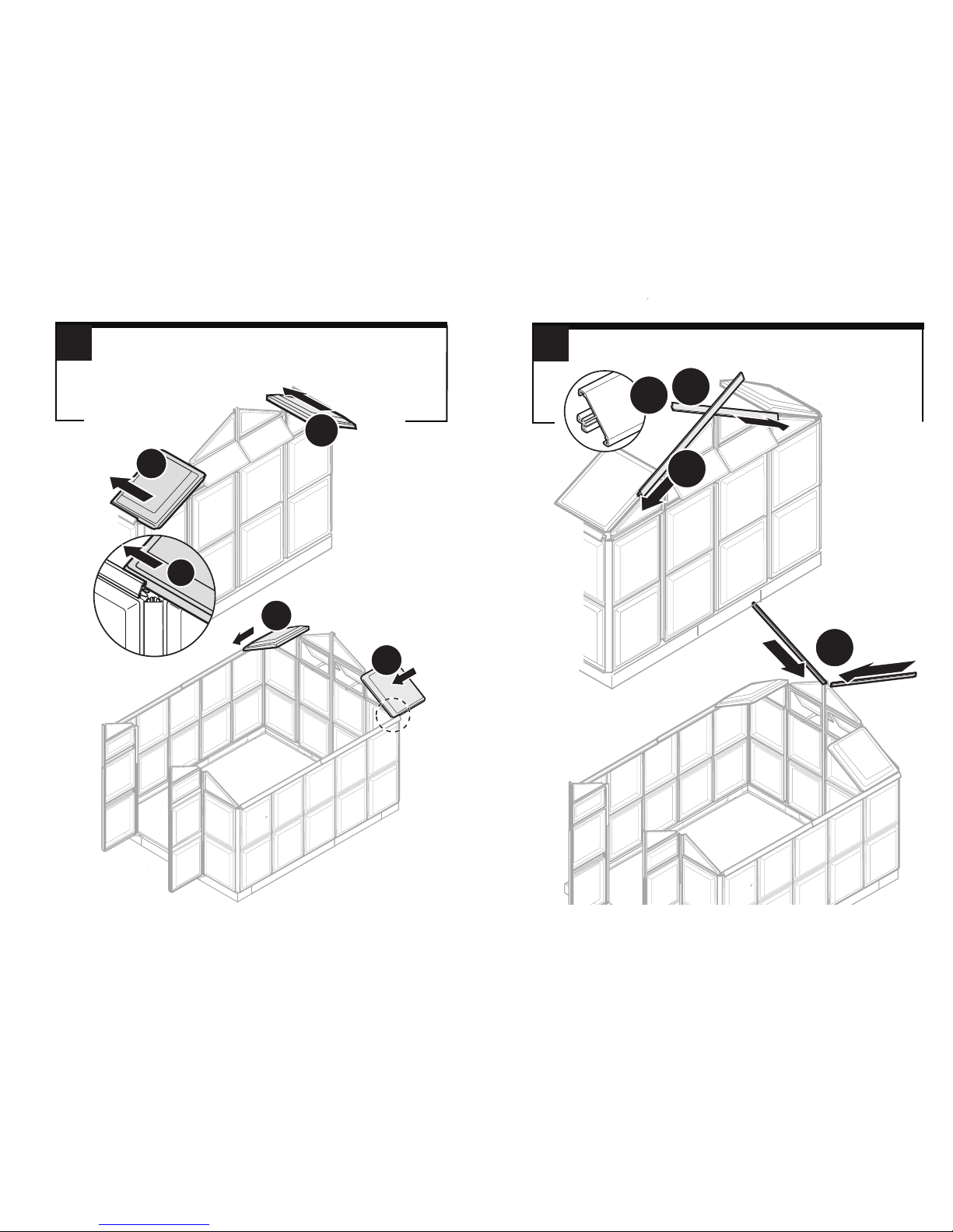
50
49
Slide two panels P4 onto the profiles A39/1490, one on each
side (this is the beginning of installing the panels on the roof).
P4
P4
P4
P4
P4
A13
1390
Slide two corner profiles A13/1390 (one on each side) on triangle
panels P6, simultaneously with sliding along panels P4 (just
mounted).
A13
1390
A13
1390
A13
1390
P4
P6
P6
P4
P6
Page 29
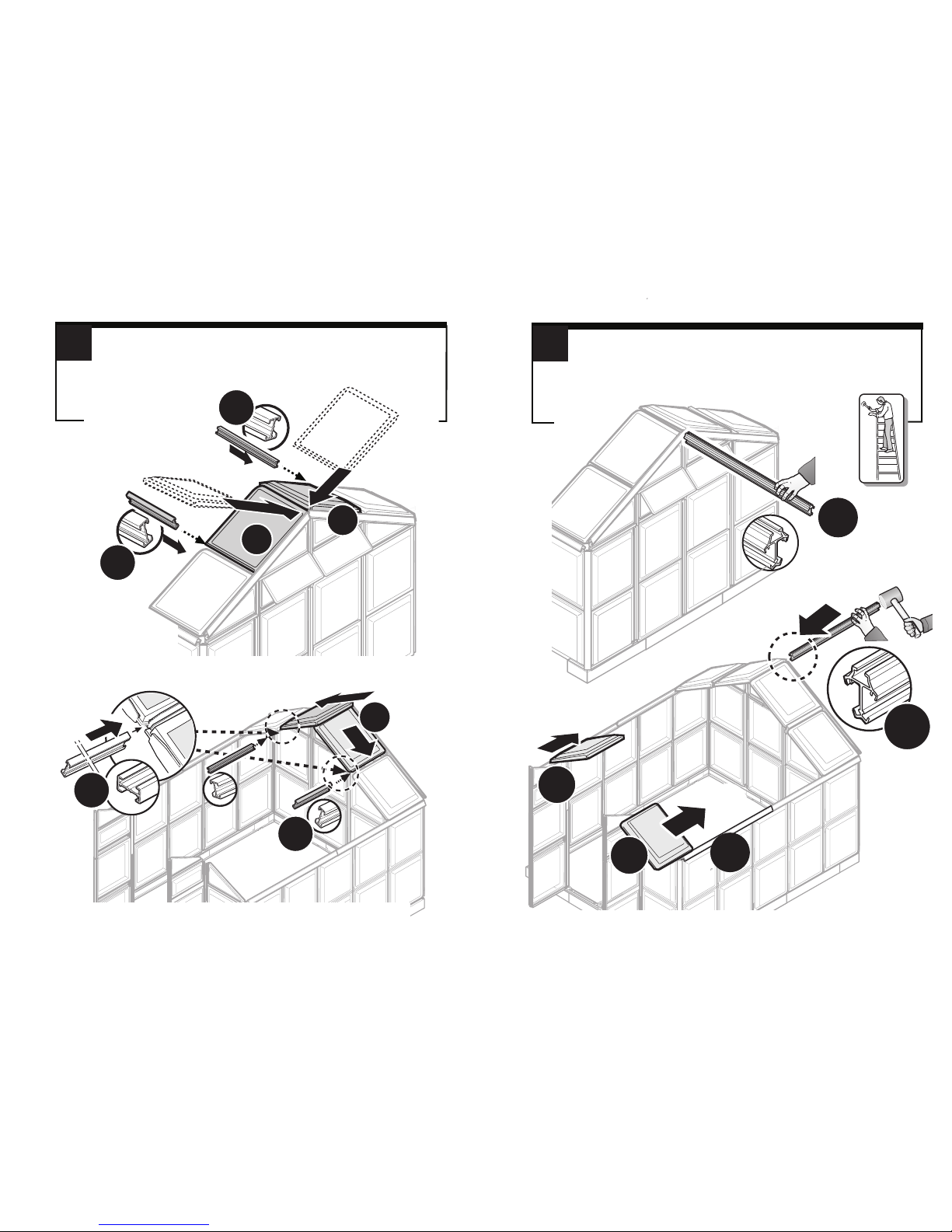
51
A11
590
P4
(b)
(b)
(a)
(a)
A11
590
P4
(a)
(a)
(b)
A11
590
A11
590
(b)
P4
(b)
Slide two additional panels P4 (a) into corner profiles A13/1390
(one on each side), and interconnect each P4’s couple (one on
each side) by inserting profile A11/590 between them (b).
52
(a)
A40
1495
P4
(b)
P4
(b)
A40
1495
(a) Slide apex aluminum profile A40/1495 to fasten apex panels
P4.
(b) On each side of the roof, slide from the front backwards, two
panels P4 (one on each side) along A39/1490, until it touches
the previously mounted roof panels.
A39
1495
Page 30
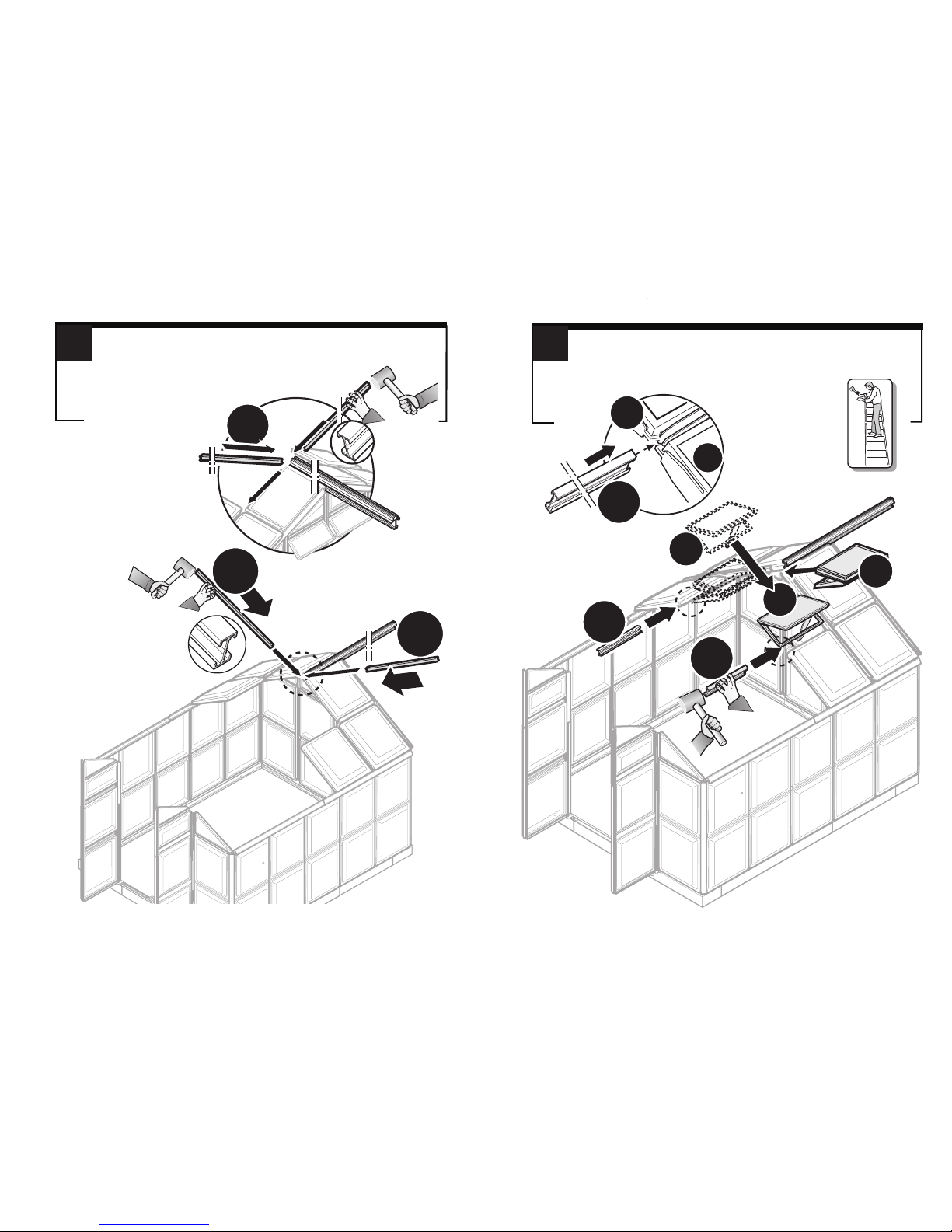
54
53
A11
1390
A11
1390
A11
1390
Slide an A11/1390 profile (one on each side) along the two
slanted P4 panels, interlocking with just added P4 panels.
(a)
(b)
(b)
A11
590
P7
P7
P7
A11
590
(a) Take two assembled vent assemblies P7 and slide them
along the just inserted profile A11/1390.
(b) Join the vent with panel P4 under it by driving profile
A11/590 between them.
(b)
A11
590
P4
P7
Page 31
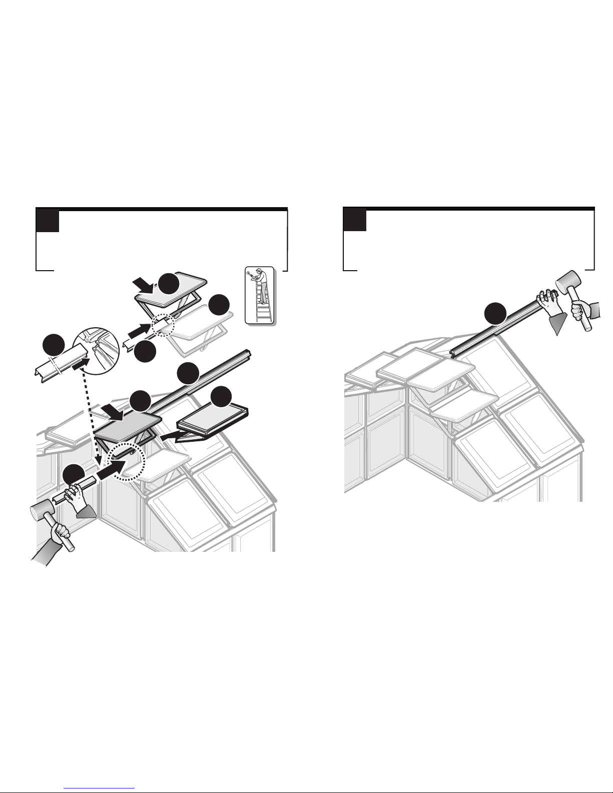
56
55
A38
590
(b)
6
P7
P7
(b)
A38
590
(a)
P7
(b)
A38
590
(a)
(a)
P7
(a) Along profiles A11/1390, slide one more vents P7 on top
of the previous ones. (b) Secure them by introducing profile
A38/590.
IMPORTANT – ensure that the flat rectangular surface is facing
outwards
A40
1495
Drive the apex profile A40/1495 forward, but do not p ass the
front edges of the windows.
A40
1495
Page 32
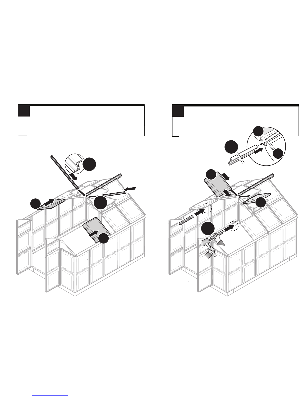
58
57
(a)
(a)
(b)
(b)
A11
1390
A11
1390
P4
P4
Continue the roof assembly operation by repeating the steps
done so far.
(a)
(b)
A11
590
P4
(b)
A11
590
P4
P4
(a)
P4
(b)
Same as step 51
Page 33
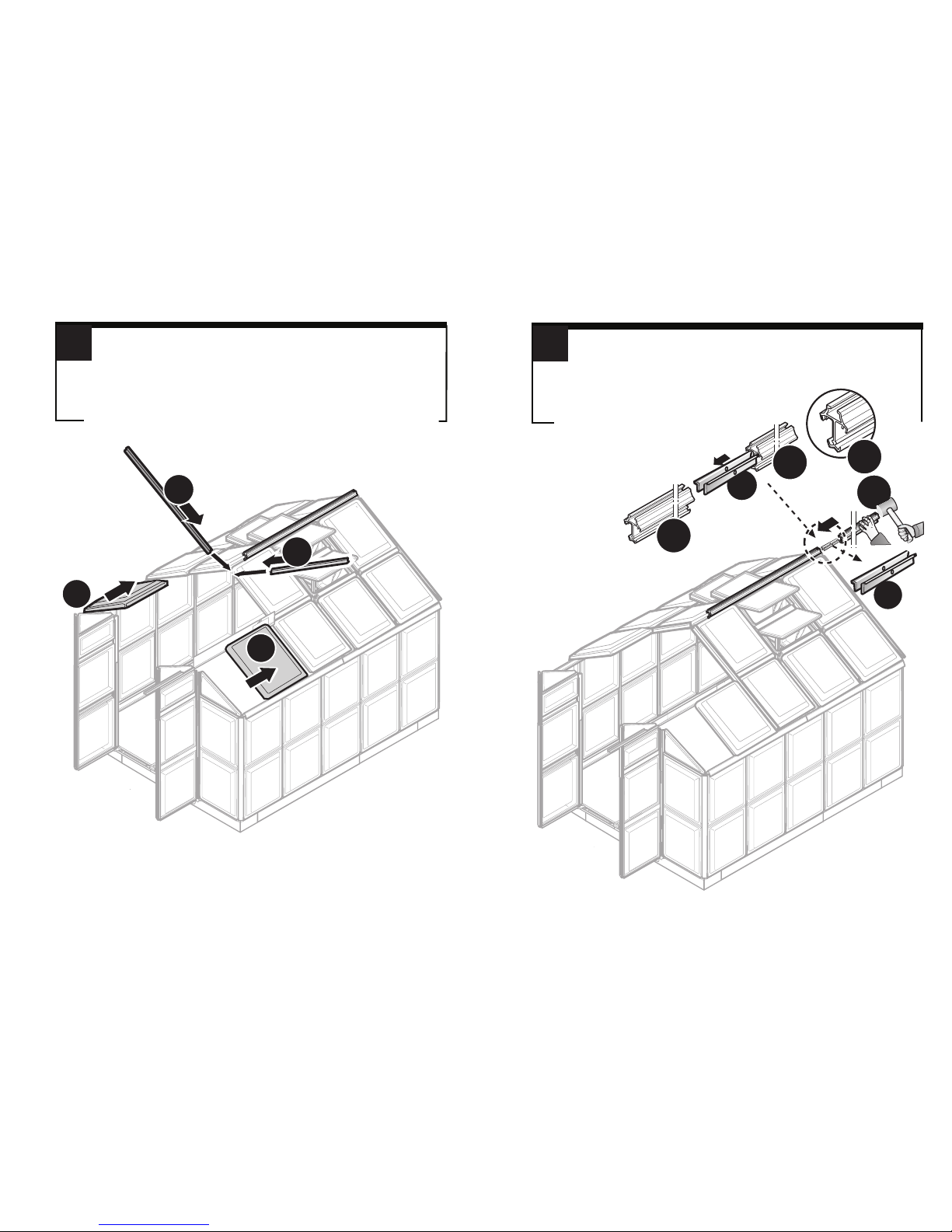
60
59
M10d
A40
1495
A40
1495
A40
1495
M10d
A40
1495
(a)
(b)
A11
1390
A11
1390
P4
P4
(b)
(a)
Same as step 57
(a) .Insert a joining bar M10d between existing apex profile
A40/1495 and an additional A40/1495 on the outside.
Page 34
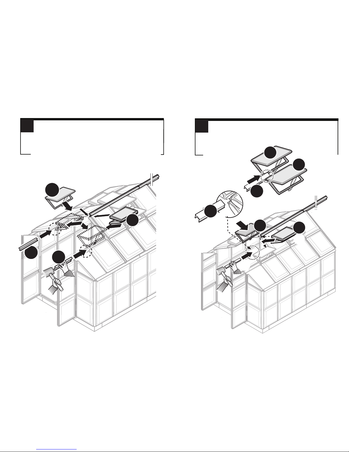
62
61
A11
590
(b)
P7
A11
590
(a)
6
P7
(a)
(b)
6
6
P7
P7
(b)
A38
590
(a)
(b)
A38
590
(b)
P7
(a)
P7
Install the two upper vents and their fastening by profile
A38/590.
Same as 54 (you continue going around the Greenhouse
structure).
Page 35
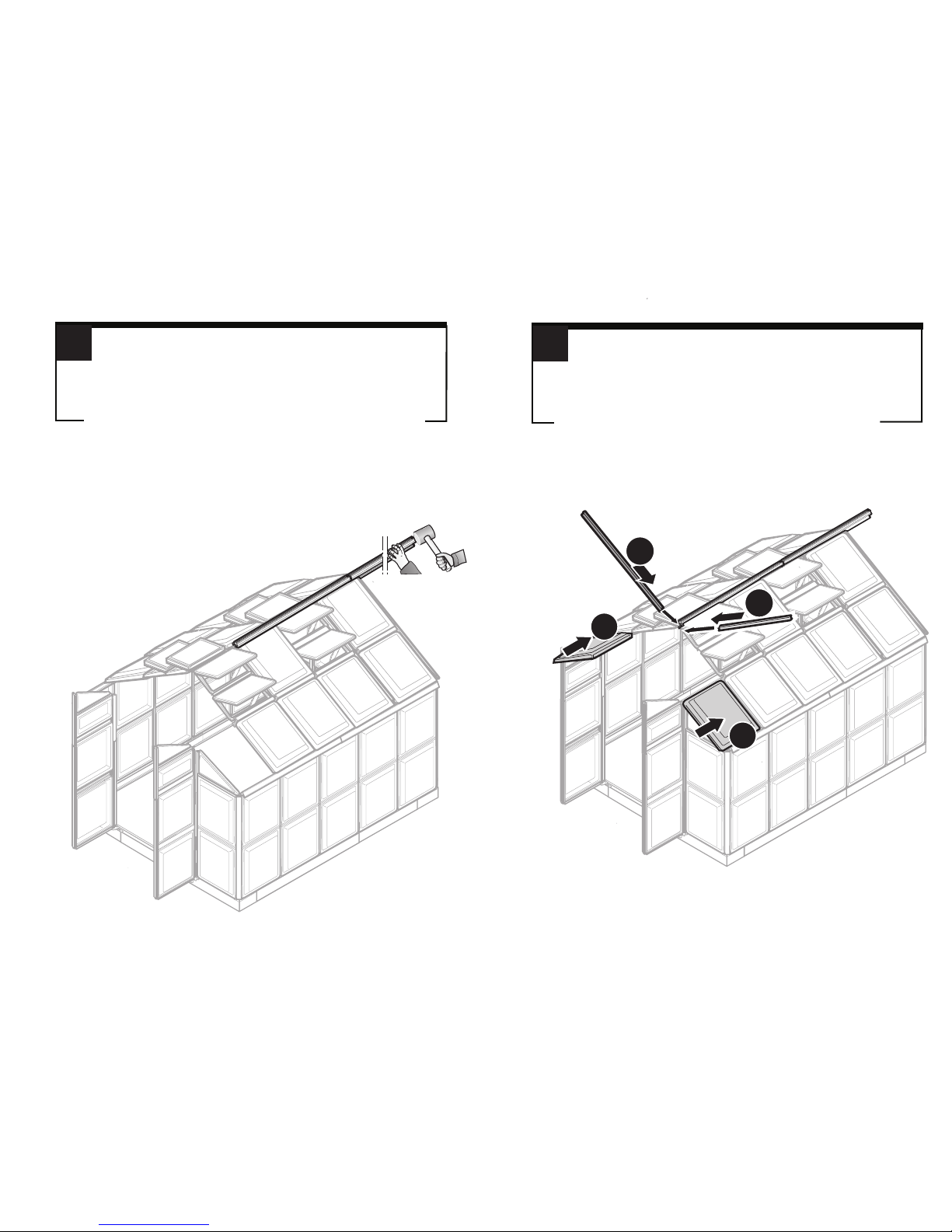
64
63
(b)
P4
(b)
A11
1390
A11
1390
(a)
(a)
P4
Continue assembling P4 roof panels as in the preceding step s,
all the way to the front roof panels.
Conclude by pushing A40/1495 all the way to the front.
Same as step 56.
Page 36
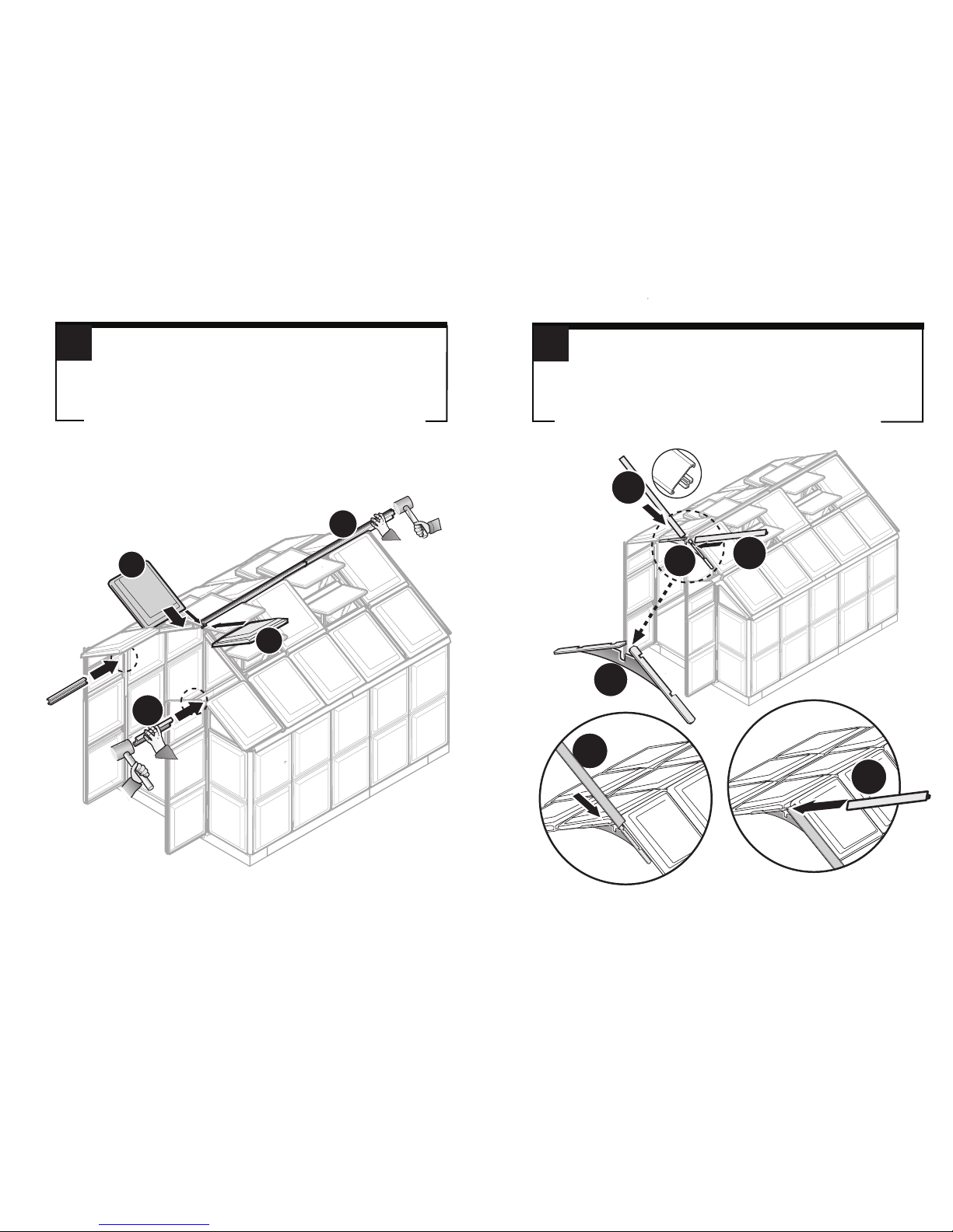
66
65
(b)
(c)
A11
590
(b)
(a)
(a)
P4
P4
Continue assembling P4 roof panels as in the preceding step s,
all the way to the front roof panels.
Conclude by pushing A40/1495 all the way to the front.
A40
1495
A13
1390
Hold fastening / bridging unit M44 along the front apex of the
roof (front edges of P4).
Slide corner profile A13/1390 so that it connects the right hand
front edges of P4’s and the slanted top of M44. Repeat the
operation on the left by driving another corner profile A13/1390
to fasten the left hand front roof panels with the lef t side of M44.
M44
M44
A13
1390
A13
1390
A13
1390
(a)
(b)
(b)
(a)
Page 37
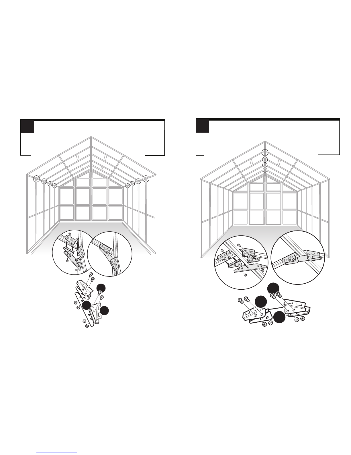
67
Use pairs of roof brackets “M46/M50” to clamp each wall section
where shown (in small circles, side walls to roof joints). Fix
bracket in place using 12 mm screws M22. Tighten with care.
INSIDE
(a)
INSIDE
(b)
INSIDE
M22
M50
M46
68
INSIDE
Use pairs of roof brackets “M45/M50” to clamp each roof section
where shown (along the apex - in small circles). Fix each bracket
in place using 12 mm screws M22. Tighten with care.
INSIDE
(b)
M50
M22
M45
(a)
Page 38
69
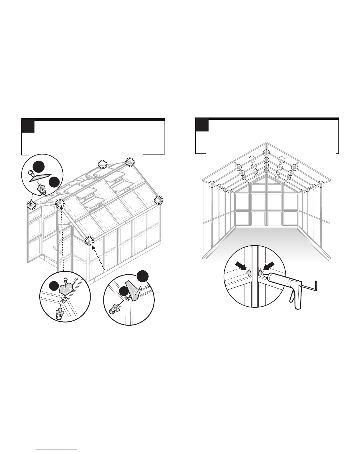
Attach corner caps C55 in all six positions (front and back) using
screws M22 - 40mm.You will need someone to help you with the step
(one person inside, another outside). Do not over tighten.
M41
8mm
OUTSIDE
INSIDE
C55
OUTSIDE
C55
INSIDE
C55
M22
40mm
INSIDE
70
From inside the greenhouse, apply silicone sealant to all the
roof joint gaps as shown.
Inject the silicone generously until it oozes from the other side.
M22
40mm
Page 39
72
71
(A)
M44
M22
M44
OUTSIDE
INSIDE
DOOR
OUTSIDE
INSIDE
DOOR
M19
M19
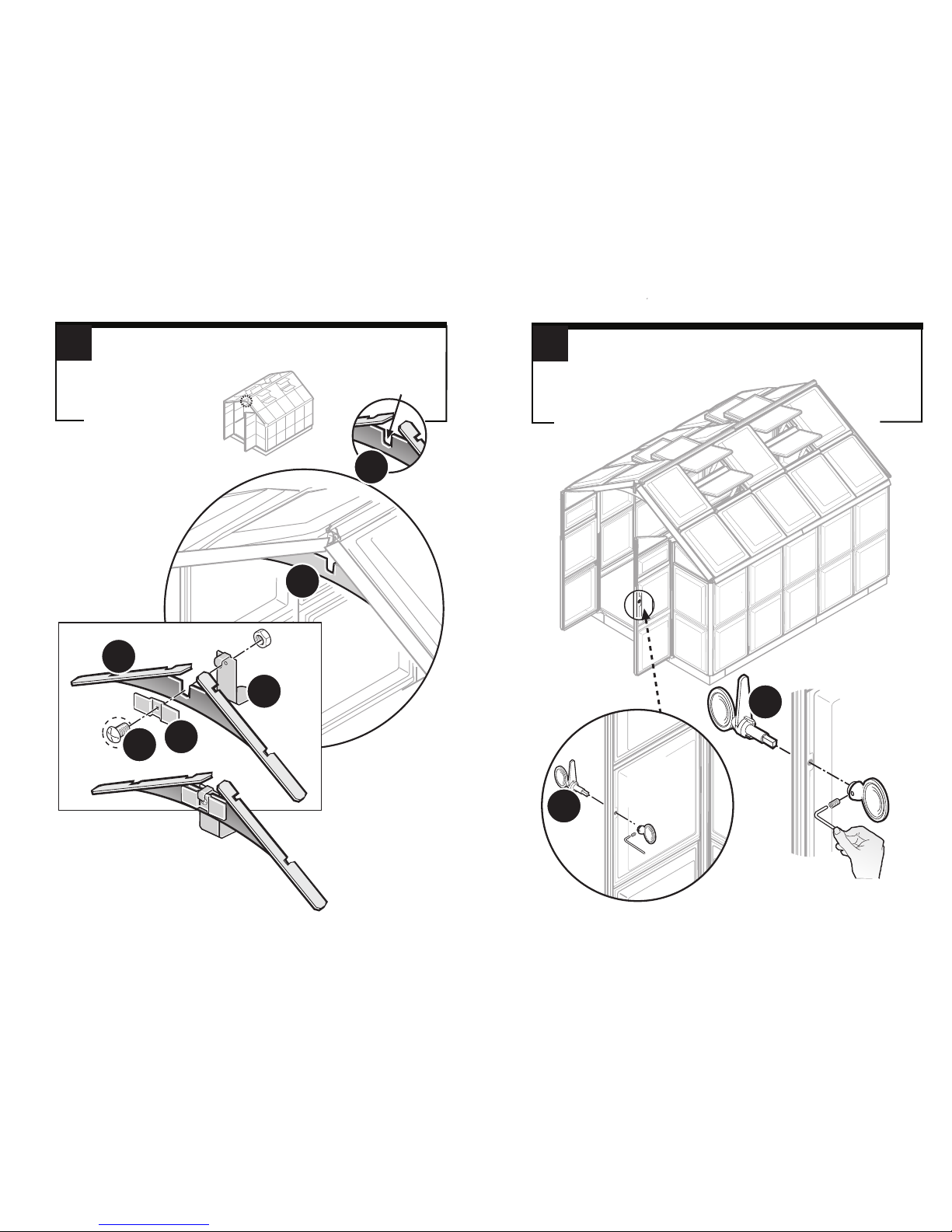
Install door handle M19 in the hole bored the in right hand side
door.
See inside / outside proper mounting position.
INSIDE
OUTSIDE
M44
M52
M49
Connect parts M49 and M52 to M44 as shown in the drawing.
These two items constitute the Left Hand door's stopper.
 Loading...