

Paloma PH-28RIFSN, PH-28RIFSP, PTG-74PV Installation And Operating Instruction Manual
FOR YOUR SAFETY!
— Do not store or use gasoline or other
flammable vapors or liquids or other
combustible materials in the vicinity of this or
any other appliance. To do so may result in an
explosion or fire.
— WHAT TO DO IF YOU SMELL GAS
● Do not try to light any appliance.
● Do not touch any electrical switch; do not
use any phone in your building.
● Immediately call your gas supplier from a
neighbor’s phone. Follow the gas
supplier’s instructions.
● If you cannot reach your gas supplier, call
the fire department.
● Do not return to your home until authorized
by the gas supplier or fire department.
— Improper installation, adjustment,
alteration, service or maintenance can cause
property damage, personal injury, or death.
Refer to this manual. Installation and service
must be performed by a qualified installer,
service agency or the gas supplier.
!
WARNING: If the information in these instructions is not followed exactly,
a fire or explosion may result causing property damage, personal injury or death.
!
The purpose of this manual is twofold: one, to provide the installer with
the basic directions and recommendations for the proper installation and
adjustment of the water heater; and two, to the owner–operator, to
explain the features, operation, safety precautions, maintenance and
troubleshooting of the water heater. This manual also includes a parts
list.
It is imperative that all persons who are expected to install, operate or
adjust this water heater read the instructions carefully so they may
understand how to perform these operations. If you don’t understand
these instructions or any terms within it, seek professional advice.
Any questions regarding the operation, maintenance, service or
warranty of this water heater should be directed to the seller from whom
it was purchased, local distributor or Paloma.
Do not destroy this manual. Please read carefully and keep in a safe
place for future reference.
Recognize this symbol as an indication of Important Safety
Information!
California Proposition 65 Warning: This product contains
chemicals known to the State of California to cause cancer, birth
defects or other reproductive harm.
!
!
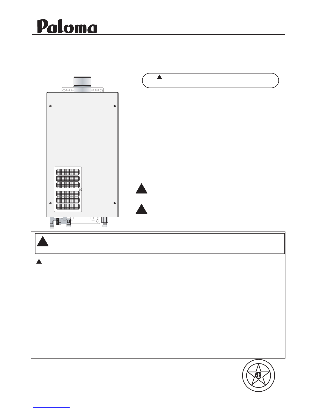
Installation and Operating Instruction Manual
With Installation Instructions for the Installer
Models:
PH-28RIFSN (Natural Gas)
PH-28RIFSP (L.P. Gas)
Tankless Water Heater
D
E
S
I
G
N
C
E
R
T
I
F
I
E
D
®
Warning: This water heater is not suitable
for use in manufactured (mobile) homes!
!
Residential Indoor Gas
199,900 BTU Max Input

Safety Information
Safety Precautions . . . . . . . 3–6
LP Gas Models . . . . . . . . . . . 5
Installation Instructions
Location . . . . . . . . . . . . . . . . . 7
Water Connections. . . . . . 9-10
Gas Supply . . . . . . . . . . . . . . 11
High Altitude . . . . . . . . . . . . 11
Venting . . . . . . . . . . . . . . 12-16
Remote Control. . . . . . . . 17-18
Electrical Connection . . . . . . 19
Typical Installation . . . . . . . . 20
Pipe Insulation . . . . . . . . . . . 21
Installation Checklist . . . . . . 22
Operating Instructions
Lighting Instructions . . . . . . 23
Water Temperature. . . . . 24, 25
Care and Cleaning
Maintenance. . . . . . . . . . . . . 26
Housekeeping . . . . . . . . 26, 27
Vent Inspection . . . . . . . . . . . 27
Burner Inspection . . . . . . . . 27
Extended Shut-Down . . . . . . 27
Draining . . . . . . . . . . . . . . . . 28
Troubleshooting Tips
Before You Call
For Service . . . . . . . . . . . 29,30
Parts List . . . . . . . . . . . . . . . 31
Warranty. . . . . . . . . . . . . . 32,33
Specifications. . . . . . . . . . . . 34
Inside you will find many helpful hints on how to use and
maintain your water heater properly. A little preventive care on
your part can save you time and money over the life of your
water heater.
You’ll find many answers to common problems in the
Troubleshooting Guide. If you review the chart of
Troubleshooting Tips first, you may not need to call for service.
READ THIS MANUAL
FOR YOUR RECORDS
Write the model and serial numbers here:
#
#
You can find them on a label on the appliance.
Staple sales slip or cancelled check here.
Proof of the original purchase date is needed to obtain service
under the warranty.
2
Your safety and the safety of others are very important. There
are many important safety messages in this manual and on
your appliance. Always read and obey all safety messages.
This is the safety alert symbol. Recognize this symbol
as an indication of Important Safety Information!
This symbol alerts you to potential hazards that can
kill or hurt you and others.
All safety messages will follow the safety alert symbol and
either the word “DANGER”, “WARNING”, “CAUTION” or
“NOTICE”.
These words mean:
DANGER
An imminently hazardous situation
that will result in death or serious
injury.
WARNING
A potentially hazardous situation that
could result in death or serious injury
and/or damage to property.
CAUTION A potentially hazardous situation that
may result in minor or moderate
injury.
Notice:
Attention is called to observe a
specified procedure or maintain
a specific condition.
!
!
!
!
READ THE SAFETY INFORMATION
Be sure to read and understand the entire Instruction Manual before attempting to install or operate
this water heater. It may save you time and money. Pay particular attention to the Safety Instructions.
Failure to follow these warnings could result in serious bodily injury or death. Should you have
problems understanding the instructions in this manual, or have any questions, STOP, and get help
from a qualified service technician, or the local gas utility.
IMPORTANT SAFETY INFORMATION.
READ ALL INSTRUCTIONS BEFORE USING.
3
Failure to install and properly vent the water heater to the outdoors as outlined in the
Venting Section of the Installation Instructions in this manual can result in unsafe
operation of the water heater. To avoid the risk of fire, explosion, or asphyxiation from
carbon monoxide, never operate this water heater unless it is properly vented and has an
adequate air supply for proper operation. Be sure to inspect the vent system for proper
installation at initial start-up; and at least annually thereafter. Refer to the Care and
Cleaning section of this manual for more information regarding vent system inspection.
DANGER!
INSTALL AND PROPERLY VENT THE WATER HEATER…
!
Gasoline, as well as other flammable materials and liquids (adhesives, solvents, paint
thinners etc.), and the vapors they produce are extremely dangerous. DO NOT handle,
use or store gasoline or other flammable or combustible materials anywhere near or in the
vicinity of a water heater or any other appliance. Be sure to read and follow the labels on
the water heater, as well as the warnings printed in this manual. Failure to do so can
result in property damage, bodily injury or death.
WARNING!
!
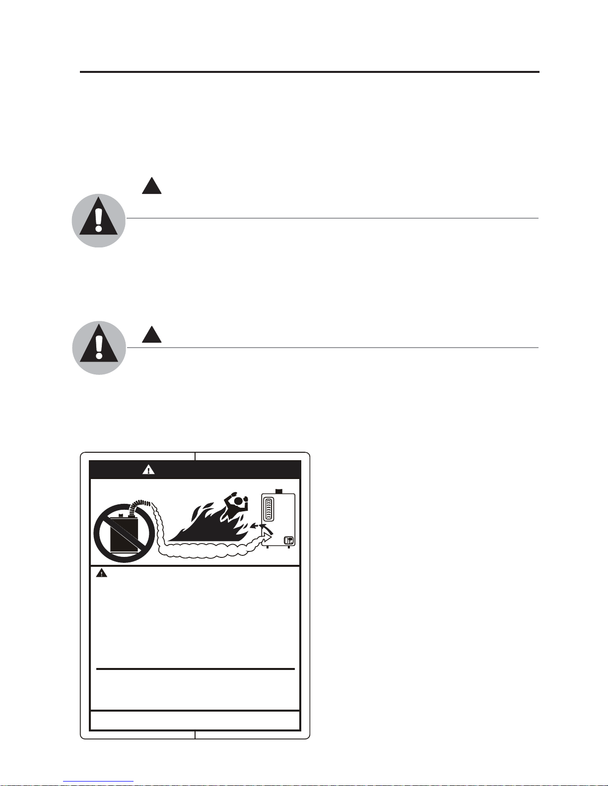
DANGER
FLAMMABLES
Flammable Vapors
Water he ater has a ma in
burner flame.
The main burner flame:
1. which c an come on
at any time and
2. will ignite flammable
vapo rs.
Vapors:
1. cannot be seen,
2. are heavier than air,
3. go a long way on the
floo r and
4. can be carried from
other r ooms to the
main burner flame by
air currents.
Vapors from flammable
liquids will explode and
catch fire causing death or
severe burns.
Do not use or store flammable
products such as gasoline,
solvents or adhesives in the
same room or area near the
water heater.
Keep flammable products:
1. far away from heater,
2. in approved containers,
3. tightly closed and
4. out of children's reach.
Installation:
Do not install water heater
where flammable products will
be stored or used unless the
main burner flame is at least
18" above the floor. This will
reduce, but not eliminate, the
risk of vapors being ignited
by the main burner flame.
Read and follow water heater warnings and instructions. If
owners manual is missing, contact the retailer or manufacturer.

Time/Temperature Relationship in Scalds
Water Temperature Time To Produce a Serious Burn
120°F More than 5 minutes
125°F 11/2 to 2 minutes
130°F About 30 seconds
135°F About 10 seconds
140°F Less than 5 seconds
145°F Less than 3 seconds
150°F About 11/2 seconds
155°F About 1 second
Table courtesy of Shriners Burn Institute
The chart shown above may be used as a guide
in determining the proper water temperature for your
home.
DANGER: Households with small children,
disabled, or elderly persons may require a 120°F. or
lower temperature setting to prevent contact with
“HOT” water.
Maximum water temperature occurs while burner is
on. To find water temperature being delivered, turn
on a hot water faucet and place a thermometer in the
water stream and read the thermometer.
(See page 24 & 25 for more details.)
The temperature of the water at the outlet of the
water heater can be regulated by setting the
temperature on Remote Control. The remote control
was set at 100°F before it was shipped from the
factory.
The illustration to the bottom left illustrates the
Remote Control and how to adjust the water
temperature.
Notice: When this water heater is supplying general
purpose hot water requirements for use by
individuals, a thermostatically controlled mixing
valve for reducing point of use water temperature is
recommended to reduce the risk of scald injury.
Contact a licensed plumber or the local plumbing
authority for further information.
Notice: The factory setting allows operating
temperatures between 100°F and 120°F.
Temperatures of up to 140°F can be achieved with
the MAIN (UMC-117) (sold separately) remote
control and a dip switch adjustment. Contact the
dealer, distributor, or Paloma to purchase the MAIN
(UMC-117) remote control. Only qualified service
personnel should perform this adjustment. Only
factory authorized remote control(s) should be used.
DANGER
!
HOT
Water temperature over 125°F can
cause severe burns instantly or
death from scalds.
Children, disabled and elderly are
at highest risk of being scalded.
See instruction manual before
setting temperature at water
heater.
Feel water before bathing or
showering.
Temperature limiting valves are
available, see manual.
BURN
DANGER!
WATER TEMPERATURE SETTING
!
Safety and energy conservation are factors to be considered when selecting the water
temperature setting of a water heater’s remote control. Water temperatures above 125°F
can cause severe burns or death from scalding. Be sure to read and follow the warnings
outlined on the label pictured below.
4
IMPORTANT SAFETY INFORMATION.
READ ALL INSTRUCTIONS BEFORE USING.
!
°F
PRIORITY
POWER
ON/OFF
100 102 104 106 108 110 112 114 116 118 120 130* 140* °F
Higher (Hotter) Lower (Cooler)
*Requires the optional MAIN (UMC-117) remote control (Sold Separately).
Tepid Hot Hotter Hottest

5
Both LP and natural gas have an odorant added to aid in detecting a gas leak. Some
people may not physically be able to smell or recognize this odorant. If you are unsure or
unfamiliar with the smell of LP or natural gas, ask the gas supplier. Other conditions, such
as “odorant fade”, which causes the odorant to diminish in intensity, can also hide or
camouflage a gas leak.
DANGER!
NATURAL GAS AND LIQUEFIED PETROLEUM MODELS
!
● Water heaters utilizing LP gas are
different from natural gas models. A
natural gas water heater will not function
safely on LP gas and vice versa.
● No attempt should ever be made to
convert the water heater from natural
gas to LP gas. To avoid possible
equipment damage, personal injury or
fire, do not connect the water heater to a
fuel type not in accordance with the unit
data plate; propane for propane units
and natural gas for natural gas units.
These units are not certified for any
other fuel type.
● LP appliances should not be installed
below grade (for example, in a basement)
if such installation is prohibited by
federal, state and/or local laws, rules,
regulations or customs.
● Propane or LP gas must be used with
great caution. It is heavier than air and
will collect first in lower areas making it
hard to detect at nose level.
● Before attempting to light the water
heater, make sure to look and smell for
gas leaks. Use a soapy solution to check
all gas fittings and connections. Bubbling
at a connection indicates a leak that must
be corrected. When smelling to detect a
gas leak, be sure to sniff near the floor
also.
● Gas detectors are recommended in LP
and natural gas applications and their
installation should be in accordance with
the detector manufacturer’s
recommendations and/or local laws,
rules, regulations or customs.
● It is recommended that more than one
method, such as soapy solution, gas
detectors, etc., be used to detect leaks in
gas applications.
Notice: If a gas leak is present or suspected:
● Do not attempt to find the cause yourself.
● Do not
try to light any appliance.
● Do not
touch any electrical switch.
● Do not
use any phone in your building.
● Leave the house immediately and make
sure your family and pets leave also.
● Leave the doors open for ventilation and
contact the gas supplier, a qualified
service agency or the fire department.
● Stay away from the house (or building)
until the service call has been made, the
leak is corrected and a qualified agency
has determined the area to be safe.
6
Have the installer show you the location of the gas shut-off valve and how to shut it off if
necessary. Turn off the manual shut-off valve if the water heater has been subjected to
overheating, fire, flood, physical damage or if the gas supply fails to shut off.
● Read this manual entirely before
installing or operating the water heater.
● Use this appliance only for its intended
purpose as described in this Instruction
Manual.
● Be sure your appliance is properly
installed in accordance with local codes
and the provided installation
instructions.
● Do not attempt to repair or replace any
part of your water heater unless it is
specifically recommended in this
manual. All other servicing should be
referred to a qualified technician.
SAFETY PRECAUTIONS
IMPORTANT SAFETY INFORMATION.
READ ALL INSTRUCTIONS BEFORE USING.
WARNING!
For your safety, the information in this manual must be followed to minimize the risk of
fire or explosion, electric shock, or to prevent property damage, personal injury, or loss of
life.
!
FOR INSTALLATIONS IN THE STATE OF CALIFORNIA
California Law requires that residential water heaters must be braced, anchored or
strapped to resist falling or horizontal displacement due to earthquake motions. For
residential water heaters up to 52 gallon capacity, a brochure with generic earthquake
bracing instructions can be obtained from: Office of the State Architect, 400 P Street,
Sacramento, CA 95814 or you may call 916-445-8100 or ask a water heater dealer.
However, applicable local codes shall govern installation. For residential water heaters
of a capacity greater than 52 gallons or tankless-style, consult the local building
jurisdiction code for acceptable bracing procedures.
READ AND FOLLOW THIS SAFETY INFORMATION
CAREFULLY.
SAVE THESE INSTRUCTIONS
Installing the water heater.
This water heater must be installed in accordance with these instructions, local codes, utility company
requirements, and/or in the absence of local codes, use the latest edition of the American National
Standard/National Fuel Gas Code. A copy can be purchased from either the American Gas Association,
400 North Capitol Street Northwest, Washington, DC 20001 as ANSI standard Z223.1 or National Fire
Protection Association, 1 Batterymarch Park, Quincy, MA 02269 as NFPA 54. In Canada, the latest
edition of the CSA B149.1 Natural Gas and Propane Installation, and the Canadian Electrical Code,
CSA C22.1 Part 1, in the absence of local codes.
Location
The water heater should not be located
in an area where leakage of the heat
exchanger or connections will result in
damage to the area adjacent to it or to
lower floors of the structure.
When such areas cannot be avoided it is
recommended that a suitable catch pan,
adequately drained, must be installed
under the water heater.
The pan must not restrict combustion
air flow.
A gas fired water heater or any other
appliance should not be installed
in a space where liquids which give off
flammable vapors are to be used or stored.
Such liquids include gasoline, LP gas
(butane or propane), paint or adhesives and
their thinners, solvents or removers.
Because of natural air movement in a
room or other enclosed space, flammable
vapors can be carried some distance from
where their liquids are being used or
stored. The open flame of the water
heater’s main burner can ignite these
vapors causing an explosion or fire which
may result in severe burns, death or
property damage.
The water heater must be located so it is
not subject to physical damage, for example,
by moving vehicles, area flooding, etc.
If the water heater is installed in a garage,
it should be installed so that the direct
ignition system and main burner are no
less than 18 inches above the garage floor.
Raising the gas fired water heater will
reduce BUT NOT eliminate the possibility
of lighting the vapor of any flammable
liquids which may be improperly stored or
accidentally spilled.
● The water heater should be installed as
close as practical to the vent termination
to minimize vent length and the number
of elbows required for venting.
● The water heater should be installed
with the proper venting materials and
termination suitable for Category III
venting.
● Failure to install and properly venting
the water heater to the outdoors as
outlined in the Venting Section of this
manual can result in unsafe operation.
● Long hot water lines should be insulated
to conserve water and energy.
● The water heater and water lines should
be protected from exposure to freezing
temperatures.
● Do not install the water heater in
bathrooms, bedrooms, any occupied
rooms normally kept closed, or in
outdoor areas.
● Do not install the water heater in small,
poorly ventilated rooms, or in air tight
rooms with air-conditioning.
● Do not install water heater where
subject to vibrations.
● Do not install the water heater in
Recreational Vehicles, Mobile Homes,
Boats and other Watercrafts.
● Do not install the water heater near
vents for heating or cooling.
● Minimum clearance from combustible
construction is 1/2” sides, 0” rear (with
support bracket); 12” from the bottom;
12” from the front of the water heater;
and 12” from the top (24” from front
and top is recommended for servicing
purposes). Maintain a minimum
clearance of 2” around the vent pipe to
combustible construction. If the
clearances stated on the
Instruction/Warning Label, located on
the front panel of the heater differ,
install the water heater according to the
clearances stated on the label.
7
WARNING: Combustible
construction refers to
adjacent walls and ceilings
and should not be confused
with combustible or
flammable products and
materials. Combustible
and/or flammable products
and materials should never
be stored in the vicinity of
this or any gas appliance.
!
min.
1/2 "
min.
1/2 "
min. 12"
(24" minimum is
recommended for service)
Top = 12"
Vent = 2"
Front = 12"
min. 2"
min. 2"
Back = 0" (with support bracket)
Side = 1/2"
Bottom = 12"
Minimum Clearance
from
Combustible Construction
Vent Pipe
3" min
2" min
2" min
8
Installing the water heater.
Proper operation of the water heater requires air for combustion and ventilation. Provisions for
combustion and ventilation air must comply with referenced codes and standards.
Combustion and Ventilation Air
NOTICE: If the water heater is installed in
an unconfined space within a building of
conventional frame, masonry or metal
construction, infiltration air is normally
adequate for proper combustion and
ventilation. If the water heater is installed in
a confined space, provisions for combustion
and ventilation air must be made.
A confined space is one having a volume
of less than 50 cubic feet per 1000 Btuh of
the aggregate input of all appliances
within that space.
The air must be supplied through two
permanent openings of equal area. One
is to be located within 12” above the floor
and the other is to be located within 12”
below the ceiling.
The minimum net free area of each opening
must not be less than one square inch per
1000 Btuh of the total input rating of all
the appliances in the enclosure (but not
less than 100 square inches), if each
opening communicates with other
unconfined areas inside the building.
Buildings of unusually tight construction
shall have the combustion and ventilation
air supplied from outdoors, or a freely
ventilated attic or crawl space.
If air is supplied from outdoors, directly or
through vertical ducts, there must be two
openings located as specified above and
each must have a minimum net free area
of not less than one square inch per 4000
Btuh of the total input rating of all the
appliances in the enclosure.
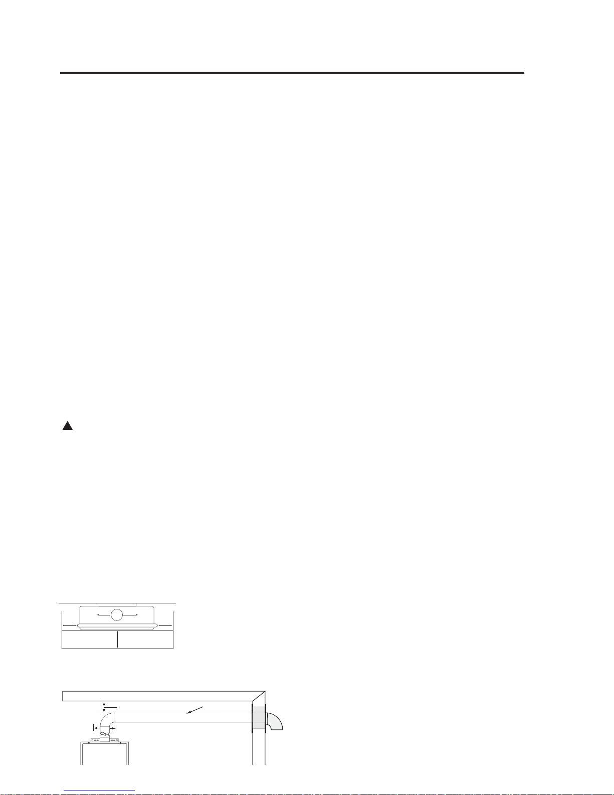
If horizontal ducts are used to
communicate with the outdoors, each
opening must have a minimum net free
area of not less than one square inch per
2000 Btuh of the total input rating of all
the appliances in the enclosure. If ducts
are used, the minimum dimensions of
rectangular air ducts shall not be less than
3”.
NOTICE: If the duct openings which supply
combustion and ventilation air are to be
covered with a protective screen or grill, the
net free area (openings in the material) of
the covering material must be used in
determining the size of the openings.
Protective screening for the openings MUST
NOT be smaller than 1/4”mesh to prevent
clogging by lint or other debris.
Corrosive Atmospheres
The air in beauty shops, dry cleaning
establishments, photo processing labs,
and storage areas for liquid and powdered
bleaches or swimming pool chemicals
often contain such halogenated
hydrocarbons.
An air supply containing halogenated
hydrocarbons may be safe to breathe,
but when it passes through a gas flame
corrosive elements are released that
will shorten the life of any gas burning
appliance.
Propellants from common spray cans or
gas leaks from A/C and refrigeration
equipment are highly corrosive after
passing through a flame.
The water heater warranty is voided when
failure of the heater is due to operation in
a corrosive atmosphere.
NOTICE: The water heater
should not be installed near
an air supply containing
halogenated hydrocarbons.
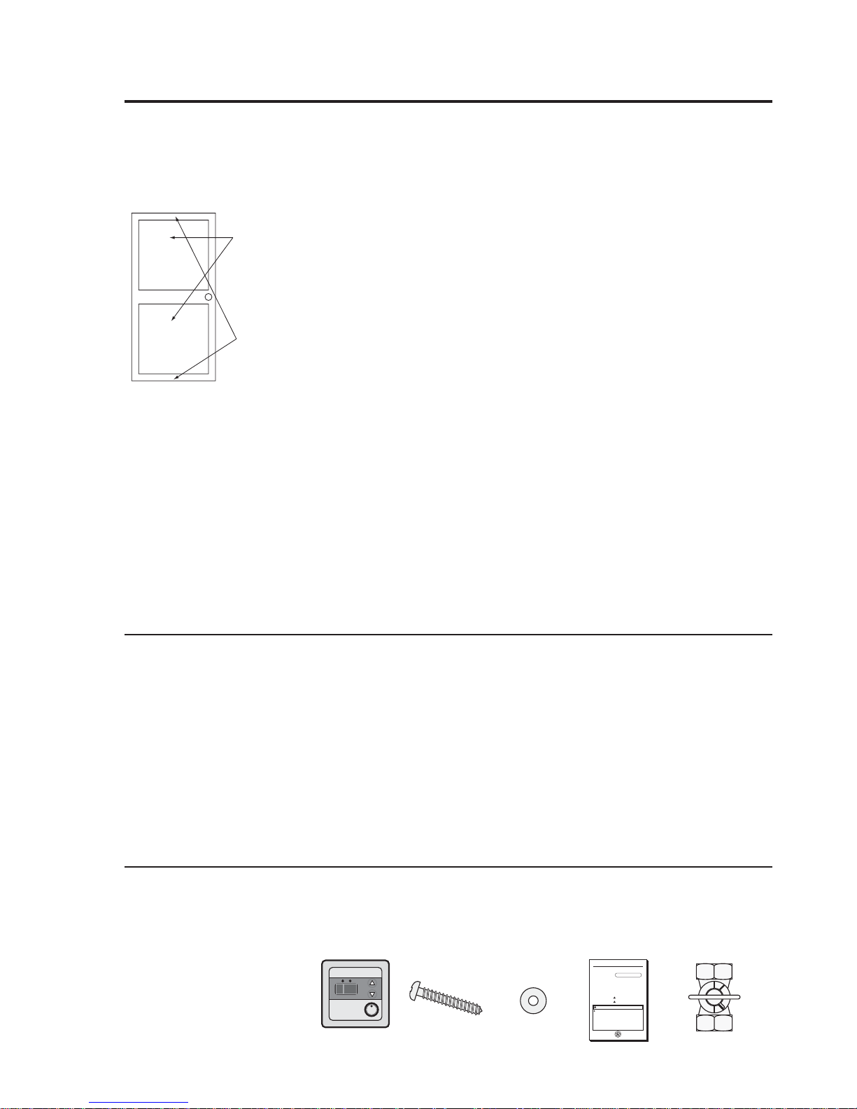
Inspect Shipment
Inspect the water heater for possible damage. Check the markings on the rating plate of
the water heater to be certain the type of gas supplied corresponds to the water heater
requirements. Verify all included parts are present (see below).
Min. 3"
Air Openings
Min. 200 Sq. In.
Manual Appliance
Gas Shut-off Valve
Instruction Manual
Wood Screw x 5pcs.
Washer x 4 pcs.
Tankless Unit
FOR YOUR SAFETY!
—Do not store or use gasoline or other
flammable vapors or liquids or other
combustible materials in the vicinity of this or
any otherappliance. To do so may result in an
explosion orfire.
—WHATTO DO IFYOU SMELL GAS
●Do not try to light any appliance.
● Do not touch any electrical switch; do not
use any phone in yourbuilding.
● Immediately call yourgas supplierfrom a
neighbor’s phone. Follow the gas
supplier’s instructions.
● If you cannot reach yourgas supplier, call
the fire department.
● Do not return to yourhome until authorized
by the gas supplierorfire department.
— Improperinstallation, adjustment,
alteration, service ormaintenance can cause
property damage, personal injury, ordeath .
Referto this manual. Installation and service
must be performed by a qualified installer,
service agency orthe gas supplier.
!
WARNING: If the information in these instructions is not followed exactly,
a fire orexplosion may result causing property damage, personal injury ordeath.
!
The purpose of this manual is twofold: one, to provide the installerwith
the basic directions and recommendations forthe properinstallation and
adjustment of the waterheater; and two, to the owner–operator, to
explain the features, operation, safety precautions, maintenance and
troubleshooting of the waterheater. This manual also includes a parts
list.
It is imperative that all persons who are expected to install, operate or
adjust this waterheaterread the instructions carefully so they may
understand how to perform these operations. If you don’t understand
these instructions orany terms within it, seek professional advice.
Any questions regarding the operation, maintenance, service or
warranty of this waterheatershould be directed to the sellerfrom whom
it was purchased. If additional information is required, referto the
section on How to Obtain Service Assistance.
Do not destroy this manual. Please read carefully and keep in a safe
place forfuture reference.
Recognize this symbol as an indication of Important Safety
Information!
California Proposition 65 Warning:This product contains
chemicals known to the State of California to cause cancer, birth
defects orotherreproductive harm.
!
!
Use & Care Manual
With Installation Instructions for the Installer
Printed in USA
Water Heaters
Residential Gas
Warning: This waterheateris not suitable for
use in manufactured (mobile) homes!
Tankless
D
E
S
I
G
N
C
E
R
T
I
F
I
E
D
®
°F
PRIORITY
POWER
ON/OFF
Remote Control
Assembly Kit

9
Water Supply Connections
IMPORTANT: Do not
apply heat to the HOT or
COLD water connections. If
sweat connections are used,
sweat tubing to adapter
before fitting adapter to the
water connections on
heater. Any heat applied to
the water supply fittings
will permanently damage
the internal components of
the water heater.
Mounting the Water Heater
Make sure the location of the appliance
allows for easy access and operation.
Wall studs should be utilized when
mounting the water heater to the wall.
In case of dry wall or concrete wall use
dry wall anchors or lag bolts.
The water heater requires 120VAC/60Hz.
Have a receptacle with ground terminal
near the water heater. The length of the
power supply cord is 10 feet.
Install a wood screw for the upper bracket
with a clearance of 1/8” between the wall
and the screw head. Hang the center of the
upper bracket on the screw.
Using a wood screw and a washer, affix
the lower bracket to the wall (Left and
Right). Repeat to affix the top bracket.
The brackets can be adjusted to change
the distance between the back of the
appliance and the wall within the range of
3/8” to 1½”.
Loosen the adjustment screws of both the
top and the bottom brackets to adjust the
distance. (See diagram below)
Bracket
Bracket
Adjustment Screws
Adjustment Screws
TOP
BOTTOM
Upper Bracket
Wood Screw
Washer
Wood Screw
Washer
Washer
Wood Screw
Lower Bracket
1/8"
Clearance
Plumbing should be carried out by a
qualified plumber in accordance with local
codes.
Use approved plumbing materials only.
All material between the water supply and
the water heater must be metal.
The diameter of the pipe lines should be a
minimum of 3/4”.
To conserve energy and to prevent
freezing, insulate both cold and hot water
supply lines. DO NOT cover the drain
valves.
To ensure proper operation of the water
heater, the following water pressure
guidelines should be followed:
● Operation of the water heater requires
the minimum water pressure of 14 psi
and a minimum water flow rate of
0.66 gpm.
● Additional water pressure is required
for long pipe runs and outlet fitting(s)
water pressure drops.
● To maintain proper performance, ensure
sufficient water supply pressure. The
Required Water Pressure = Min.
Operating Water Pressure (14 psi) +
Pipe Pressure Loss + Faucet and
Shower Pressure Loss + Safety Margin
(more than 5 psi).
● To supply hot water to upper floors,
additional water pressure (0.44 psi/ft)
must be ensured. The measurement
should be calculated by the distance
between the water inlet of the water
heater (ground level) to the hot water
faucet (upper floor level).
● Well water systems should be set at a
range of 50-60 psi.
● When the water is supplied from a
water supply tank, the height of the
tank and the diameter of the pipes and
their relation to water pressure, should
be taken into consideration. Gravity
water pressure is not recommended.
Notice: If the water flow resistance of a
shower head is too high, the burner in the
water heater will fail to ignite. Keep the
shower head clean from debris that could
cause additional pressure drop.
Notice: If using mixing valves on the
outlet, choose one which prevents cold
water pressure from overcoming hot water
line pressure.
CAUTION: This water
heater must only be used
with the following water
supply system conditions:
● With clean, potable water
free of corrosive
chemicals, sand, dirt, or
other contaminates.
● With inlet water
temperatures above 32°F,
but not exceeding 120°F.
● Free of lime and scale
deposits.
● DO NOT reverse the hot
and cold water
connections. The water
heater will not operate.
!
CAUTION:
Reinforcement of the wall is
required in case the wall is
not strong enough to hold
the appliance.
!

10
Installing the water heater.
Relief Valve
A new pressure relief valve, complying
with the Standard for Relief Valves and
Automatic Gas Shut-Off Devices for Hot
Water Supply Systems, ANSI Z21.22,
must be installed at the hot water outlet
connection of the water heater at the
time of installation. Local codes shall
govern the installation of relief valves.
For safe operation of the water heater, be
sure that:
● The pressure rating of the relief valve
must not exceed 150 psi, the maximum
working pressure of the water heater as
marked on the rating plate.
● The BTUH rating of the relief valve
must equal or exceed the BTUH input
of the water heater as marked on its
rating plate.
● No valve of any type should be
installed between the relief valve and
the water heater
● Discharge from the relief valve should
be piped to a suitable drain to eliminate
potential water damage. Piping used
should be of a type approved for the
distribution of hot water.
● Hot and cold water lines should be
insulated up to the water heater. Refer
to page 21 for details.
● The discharge line must be NO
SMALLER than the outlet of the valve
and must pitch downward to allow
complete drainage (by gravity) of the
relief valve and discharge line.
● The end of the discharge line should not
be threaded or concealed and should be
protected from freezing. No valve of
any type, restriction or reducer coupling
should be installed in the discharge line.
Notice: Local codes govern the
installation of relief valves. If local codes
require that a temperature and pressure
relief valve should be installed the
manufacturer recommends a type 40XL
Watts T&P relief valve or an equivalent
model be used.
Notice: Manual operation of relief valves
should be performed at least once a year.
Turn off the electrical power and gas
shutoff valve. Lift and release lever on the
relief valve and check the manual
operation of the relief valve. You should
take precaution to avoid contact with the
hot water coming out of the relief valve
and to prevent water damage.
Notice: If the relief valve on the system
discharges periodically, a problem exists
and service to the water system is
required.
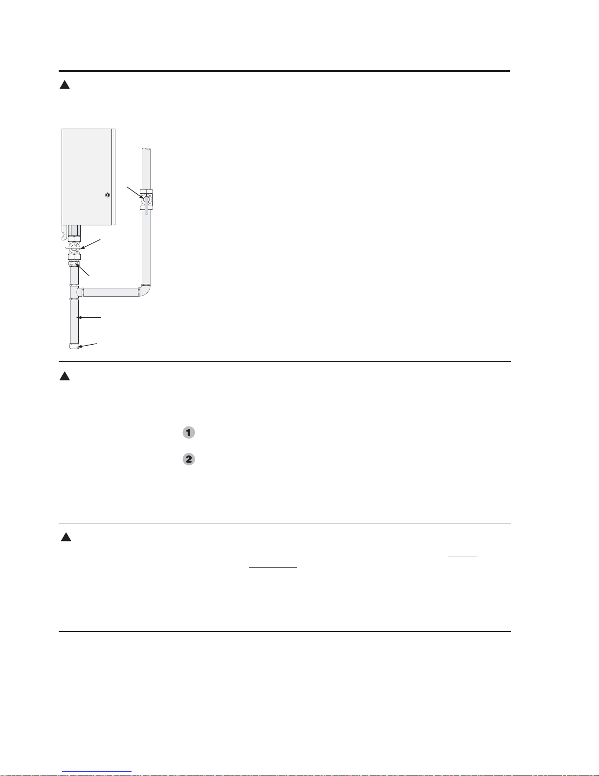
Water Supply Connections Continued.
Install a shutoff valve near the inlet of the
water heater for service and draining
purposes.
DO NOT use pipes with smaller diameters
than the water supply connection of the
water heater.
Before connecting the water supply pipe
to the water heater, open the shutoff valve
and clean out sand, debris, air, caulking
material, etc. inside the pipe. Connect to
the water inlet, then check water flow.
Close the shutoff valve and clean the
water filter.
Be sure to connect the water inlet and the
hot water outlet as shown on the water
heater. If reversed, the water heater will
not function.
Installation of unions or flexible copper
connections are recommended on the
HOT and COLD water lines, so that the
water heater may disconnect easily for
servicing if necessary.
Install a Check Valve between the water
heater and the water shutoff valve. (See
illustration the top left).
The following should be addressed in
regards to the HOT WATER OUTLET:
● Connections between the water heater
and point(s) of use should be as short
and direct as possible.
● DO NOT use lead or plastic pipe.
● To conserve energy and minimize heat
loss, insulation of hot water piping is
recommended. (See Hot and Cold Pipe
Insulation Installation on page 21).
Notice: The flow rate of hot water may
vary when more than two faucets
(appliances, fixtures, etc.) are being used
simultaneously.
Notice: The pipes MUST be completely
drainable. If the hot water faucets are
located at a point higher than the water
heater, place a drain valve at the lowest
point (see diagram to the left).
Water Filter
Check Valve
Water Inlet
Clean the
Water Filter
Wat er
Nipple
Air
Relief
Va lv e
Hot
Water
Tap
Drain Valve
Union
Pressure
Relief Valve
Water
Shutoff
Valve
Cold
Water
Supply
Inlet
Hot Water
Supply
Outlet
Relief
Valve
Discharge
Line
Notice: The above illustrates a
pressure only relief valve. If local
codes require a combination
temperature and pressure relief
valve be installed, an extension
piece may be needed. (Refer to
page 20 for example of extension
piece for T&P relief valve
installation.)
11
WARNING: Do not attempt to convert this water heater for use with a different type of gas other than the type
shown on the rating plate. Such conversion could result in hazardous operating conditions.
!
Leak Testing
The water heater and its gas connections
must be leak tested at normal operating
pressures before it is placed in operation.
Turn on the gas shut-off valve(s) to
the water heater.
Use a soapy water solution to test for
leaks at all connections and fittings.
Bubbles indicate a gas leak that must
be corrected.
The factory connections should also be
leak tested after the water heater is placed
in operation.
High Altitude
Ratings of gas appliances are based on
sea level operation and need not be
changed for installations at elevations up
to 3,280 feet.
NOTICE: For installations above 3,280
feet, the connector on the PC board
must be replaced for High Altitude
installations. Please contact your local
distributor, dealer, or Paloma for
replacement connector.
Pressure Testing the Gas Supply System
The water heater and its manual gas shutoff valve must be disconnected
from the
gas supply piping system during any
pressure testing of the system at
pressures in excess of 1/2 psi (14” w.c.).
The water heater must be isolated
from
the gas piping system by closing the
manual gas shut-off valve during any
pressure testing of the gas supply piping at
pressures equal to or less than
1/2 psi (14” w.c.).
Gas Supply
The supplied Manual Gas Appliance
Shutoff Valve must be installed at the gas
connection of the water heater at the time
of installation (see diagram to the left).
The branch gas supply line to the water
heater should be clean 3/4” black steel
pipe or other approved gas piping
material.
A ground joint union or ANSI design
certified semi-rigid or flexible gas
appliance connector should be installed in
the gas line close to the water heater. The
National Fuel Gas Code (NFGC)
mandates a manual gas shut-off valve: See
(NFGC) for complete instructions.
If flexible connectors are used, the
maximum length shall not exceed 36”.
If lever type gas shut offs are used, they
shall be T-Handle type.
Compound used on the threaded joints of
the gas piping must be of the type
resistant to the action of LP gas. Use
compound sparingly on male threads only.
A sediment trap should be installed at the
bottom of the gas line.
Do not use excessive force (over 31.5 ft
lbs.) in tightening the pipe, particularly if
teflon pipe compound is used, as the unit
may be damaged.
The inlet gas pressure to the water heater
must not exceed 10.5” w.c. for natural or
14” wc for LP gas. For purposes of input
adjustment, the minimum inlet gas
pressure (with main burner on) is shown
on the water heater rating plate. If high or
low gas pressures are present, contact your
gas supplier for correction.
WARNING: Never use
an open flame to test for
gas leaks, as property
damage, personal injury, or
death could result.
!
Manual Gas
Appliance
Shut-off
(Supplied)
Sediment
Trap
Manual
Gas
Supply
Line
Shut-off
Va lv e
Union
Cap
WARNING: Install a
gas pressure regulator, in
the gas supply line, which
does not exceed the
maximum supply pressure.
DO NOT use an industrial
type gas regulator.
!
 Loading...