

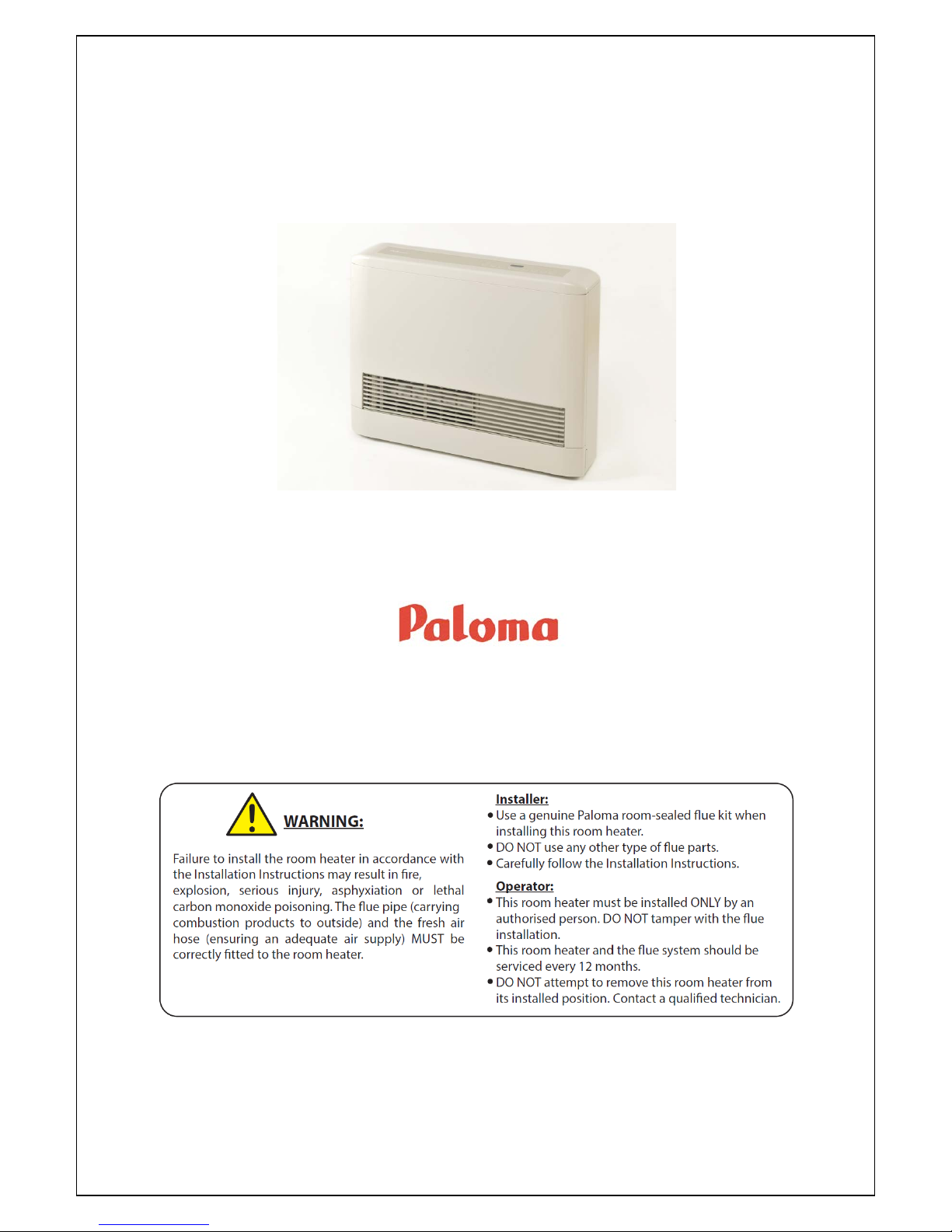
Paloma PRS-150N, PRS-250N, PRS-250CN, PRS-150L, PRS-250L Owner's Manual
...
Owner’s Guide
and
Installation Instructions
Paloma Room Sealed
Gas Space Heaters
Models
PRS-150N
PRS-250N
PRS-250CN
PRS-150L
PRS-250L
PRS-250CL
Note: This heater must be installed with a genuine Paloma room sealed flue kit. Failure to install a genuine Paloma
room sealed flue kit will result in a potentially unsafe installation and the heater warranty will become null and void.
For installation of the flue kit refer to the installation instructions supplied with the flue kit.
This heater must be installed and serviced by a qualified person.
Please leave this guide with the householder or responsible officer.

Notice to Victorian Customers from the
Victorian Building Authority
This gas space heater must be installed by a licensed person as required by
The Victorian Building Act 1993
Only a licensed person will give you a Complianc e Certificate, s howing that the work complies
with all the relevant standards. Only a licensed person will have insurance protecting their
workmanship for 6 years. Make sur e you use a licens ed person to ins tal l th is space he at er an d
ask for your Compliance Certificate.
Warning: Upon completio n of the installation and c ommis sioning of the space heater, lea ve
this guide with the householder or a responsible officer. DO NOT
leave this guide inside the
heater cover or behind the heater, as it may interfere with the safe operation of the space heater or
ignite when the heater is turned on.
Heater & Installation Information
Heater Packing Contents List
Part
Quantity
Heater
1
Back Cover Kit
Top Cover
1
RH Side Cover
1
LH Side Cover
1
Wall brackets
2
Wall Bracket Screws
2
Hexagon Bolts
4
Exhaust Connection Clamp
1
Air Intake Cable Tie
1
Control Panel Keys *
2
* PRS-250CN and PRS-250CL commercial models only.
PATENTS
This gas space heater may be protected by one or more patents or registered designs in the name of Rheem
Australia Pty Ltd or Paloma Co., Ltd.
® Registered trademark of Rheem Australia Pty Ltd.
™ Trademark of Rheem Australia Pty Ltd.
Date of installation:
Model Nº:
Serial Nº:
Installed by:
Purchased from:

CONTENTS
HOUSEHOLDER OR RESPONSIBLE OFFICER
The ‘About Your Heater’ section is intended for the householder or responsible officer.
The ‘Installation Section’ is intended for the installer but may be of interest
ABOUT YOUR HEATER .............................................................................................................................................. 4
SAFETY ....................................................................................................................................................................5
SAVE A SERVICE CALL ..........................................................................................................................................6
REGULAR CARE .....................................................................................................................................................7
OPERATION ............................................................................................................................................................8
Heater Overview ..................................................................................................................................................8
To Turn The Heater ON .......................................................................................................................................8
To Turn The Heater OFF .....................................................................................................................................9
Raising or Lowering the Set Temperature ...........................................................................................................9
Setting the Time ...................................................................................................................................................9
Timer 1 & Timer 2 Operation ...............................................................................................................................9
Auto Off Timer Operation .................................................................................................................................. 11
Economy Mode ................................................................................................................................................. 11
Child Lock Mode ............................................................................................................................................... 12
Filter Light ......................................................................................................................................................... 12
Humidifier Tray .................................................................................................................................................. 12
Vertical Louvre Adjustment ............................................................................................................................... 12
Safety Devices .................................................................................................................................................. 12
Central Control – Commercial Models Only ..................................................................................................... 12
INSTALLATION.......................................................................................................................................................... 13
Heater Location & Clearances .......................................................................................................................... 13
Minimum & Maximum Room Sizes ................................................................................................................... 14
Heater Installation Procedure ........................................................................................................................... 14
FLUEING ............................................................................................................................................................... 15
Flue Location ..................................................................................................................................................... 16
Installation Standards & Requirements............................................................................................................. 16
GAS CONNECTION .............................................................................................................................................. 18
ELECTRICAL CONNECTION ............................................................................................................................... 19
Wiring Diagram ................................................................................................................................................. 19
Central Control Connection & Operation – Commercial Models Only .............................................................. 20
CONNECTING HEATER EXHAUST & AIR INTAKE ............................................................................................ 21
Connecting Heater Exhaust .............................................................................................................................. 21
Connecting Heater Air Intake ............................................................................................................................ 22
HEATER BACK COVER KIT INSTALLATION ...................................................................................................... 23
COMMISSIONING ................................................................................................................................................. 25
Commissioning Procedure ................................................................................................................................ 25
Commissioning Tests & Adjustment Procedures .............................................................................................. 26
FAULT INDICATION ............................................................................................................................................. 29
SERVICE PROCED URES .................................................................................................................................... 30
Annual Service Procedure ................................................................................................................................ 30
DIMENSIONS AND TECHNICAL DATA ............................................................................................................... 31
WARRANTY .......................................................................................................................................................... 35
3

ABOUT YOUR HEATER
HE ATE R AP P LI CATION
This room sealed gas space heater is designed for use in a single family domestic dwelling (or commercial premises
for PRS-250CN and PRS-250CL commercial models) for the purpose of room heating. Its use in an application other
than this may shorten its life and void the product warranty.
MODEL TYPE
Congratulations for choosing a Paloma
®
room sealed gas space heater. Paloma room sealed gas space heaters are
suitable for indoor installation only and require the installation of a genuine Paloma room sealed flue kit.
HOW DO I KNOW IF THE HEATER IS INSTALLED CORRECTLY?
Installation requirements are detailed in the “Installation” section. The heater must be installed:
• by a qualified person, and
• in accordance with the installation instructions, and
• in compliance with Standards AS/NZS 3000 and AS 5601 or AS/NZS 5601.1, as applicable under local
regulations, and all local codes and regulatory authority requirements.
• In New Zealand, the insta llation mus t also conform with NZS 5261, as appl icable under loc al regulations, a nd
the New Zealand Building Code.
HOW YOUR HEATER WORKS
The heater consists of a gas burner, combustion chamber, heat exchanger, combustion fan and an air circulation fan.
Burner combustion air is dr awn fr om outdoor s by the combustion fan via the outer f lue tube. Hot combustion gases
from the burner pass through the heat exchanger and are discharged outdoors via the inner flue tube. The circulating
fan draws air from the room in which the heater is located and passes it over the heat exchanger where the air gains
heat by convection. The heated air is then circulated back into the room via the heater's front louvres. The gas supply
to the burner is controlled by an electronic controller (thermostat) which senses the room air temperature.
The following automatic safety controls are fitted to the heater:
• Filter Clean Warning Device - When the air filter is clogged or hot air outlet is blocked, the filter safety device will
switch off the heater and the filter light will flash.
• Flame Failure Device prevents flow of gas to burner if ignition fails or flame goes out.
• Power Failure Device prevents flow of gas to burner if there is a power failure.
• Overheat Safety Device – if the fan stops rotating for any reason the overheat switch shuts off the gas supply.
• Over Current Safety System.
• Air Volume and Combustion Control.
The heater has a humidif ier tra y located beh ind the lower fr ont cover. T he hum idifier tr ay can be f illed with water to
raise the humidity level in the room for extra comfort if required (refer to "Humidifier Tray Removal" on page 7).
HOW LONG WILL THE HEATER LAST?
The heater is supported by a manufacturer’s warranty (refer to “Warranty” on page 35). There are a number of factors
that will affect the length of service the heater will provide. These include but are not limited to the usage pattern and
the service and maintenance program.
REGULAR CARE AND SERVICING
The heater must be m aintained and serviced in acco rdance with the Owner’s Guide an d Installation Instructions.
Refer to “Regular Care” o n page 7.
PRECAUTIONS
Heat from this appliance may over time affect the appearance of some flooring materials such as carpet, timber, vinyl
or cork. It is recommended that a protective mat is positioned in front of the heater that extends a minimum of 750 mm
from the front of the heaters louvres to protect floor coverings.
This heater can circulate large volumes of air. If the air in the room contains any cigarette smoke or cooking vapours
the circulated air may affect the appearance of carpets, furniture and drapes, etc.
4

SAFETY
For your safety do not operate the heater before reading this instruction booklet.
Warning: This heater is designed to be instal led in a f ixed posi tio n with a Paloma room sealed flue kit (supplied
separately). The heater must not be operated unless a genuin e Pal oma room sealed flue kit is installed.
Warning: T he heater air intake hose and exh aust connection m ust both be connec ted to an approved P aloma
flue system as detailed in these installation instructions and the installation instructions supplied with the flue kit.
Warning: Ensure that the gas specified on the heater rating label matches the gas supply. Using a different gas
type may cause an explosion or cause damage to heater components. Automotive LPG fuel must not be used.
Warning: The heater uses 240 Volt AC electrical power for operat ion of the control system s. The removal of
cover(s) will expose 240 V wiring. Covers must only be removed by an authorised or qualified person.
Warning: This heater is only intended to be operated by persons who have the experience or the knowledge and
the capabilities to do so. This heater is not intended to be operated by persons (including children) with reduced
physical, sensory or mental capabilities, or lack of experience and knowledge.
Warning: Children should be supervised to ensure they do not interfere with the heater.
Warning: If the supply cord is damaged, it must be replaced by the manufacturer or its service agent or a similarly
qualified person in order to avoid a hazard.
The warranty can become void if internal components are tampered with or if the installation is not in
accordance with these instructions.
• DO ensure heater clearances are maintained at all times (refer to “Heater Clearances” table on page 13).
• DO turn the heater OFF at the control p anel when unattended or not in use. Do not turn the heater off by
switching off at the power point. The power point may be turned off when the fans have stopped cycling.
• DO NOT allow curtains or other com bustible materials to come into contact with the heat er or encroach on
heater clearances. Tie curtains back if required.
• DO NOT use or store flammable or combustible materials near the heater. Flammable liquids (such as
petrol), newspapers and similar articles must be kept well away from the heater and the flue terminal.
• DO NOT store chemicals, household cleaners, etc., near the heater.
• DO NOT use or spray aerosols, stain removers and household chemicals in the vicinity of this heater or the
flue terminal whilst it is in operation. Gases from some aerosol sprays, stain removers and household chemicals
can become flammable or corrosive when drawn into a flame.
• DO NOT place articles on or against this appliance or the flue terminal. Ensure the flue terminal is not obstructed
in any way.
• DO NOT permit persons to sleep in the warm air discharge from the heater.
• DO NOT dry articles of clothing on the heater.
• DO NOT place conta iners of liquid on top of the heater. Spillage can dam age the heater and may result in
electric shock.
• DO NOT sit on the heater.
• DO NOT allow children to insert items in the heater louvres.
• DO NOT operate heater with panels, covers or guards removed from the heater.
• DO NOT operate the heater without the air filter.
• DO NOT connect to an LPG gas cylinder located indoors.
• DO NOT use the heater if any part is faulty or damaged. Immediately call Rheem Service or Accredited service
Agent to arrange for an inspection.
• DO NOT use the heater if any part has been und er water. Imm ediately call Rheem Service or an Accredited
service Agent to arrange for an inspection.
• DO NOT modify this appliance.
5

SAVE A SERVICE CALL
Check the items below before making a service call. You will be charged for attending to any condition or
fault that is not related to manufacture or fa ilure of a part.
Note: The heater fans will continue operating for a few minutes after the heater is turned off. This is normal operation.
HEATER NOT OPERATING
• Is the electricity switched on?
Ensure the power point is turned on.
• Is there gas to the heater?
Try lighting another gas appliance. If there is no gas call your gas provider.
• Is the heater operating in a timer OFF period?
Check Timer 1 and Timer 2 settings to ensure they are suitable to enable heating when required (refer to “Timer
1 & Timer 2 Operation” on page 9). For commerc ial mode ls connected to a centr al control s ystem; ens ure the
central command system is operating and that scheduled operating times are correct.
• Is the child lock on?
Ensure the child lock is not on (refer to “Child Lock Mode” on page 12).
• Is the filter light flashing?
If the filter light is flashing the filter requires cleaning (refer to “Regular Care” on page 7).
• Is a code displayed on the controller?
Check the controllers display to see if an error code is displayed. If an error code occurs the heater will 'lock out'
and will not operate until the fault has been rectified and the heater is reset. Refer to “Fault Indication” on page
29 for a detailed list of all available codes, their meanings, suggested remedies and heater reset procedure.
HEATER NOT SUFFICIENTLY HEATING ROOM
• Is the set temperature too low?
Increase the heaters’ set temperature (refer to “Raising or Lowering the Set Temperature” on page 9).
• Is the room in which the heater is installed too large?
Do you have the correct size heater for your room size? (Refer to “Heater Maximum Room Size” on page 14).
• Is the area subjected to drafts?
Ensure windows and doors are closed and that there are no large gaps on external doors or windows where cold
air can enter.
ROOM GETS TOO HOT
• Is the set temperature too high?
Decrease the heaters’ set temperature (refer to “Raising or Lowering the Set Temperature” on page 9).
HEATER PRODUCES SMOKE AND/OR ODOUR
Warning: If you smell gas do not operate the heater. Refer to “What to do if you smell gas” on page 8.
• When operated for the first time, the heater may produce smoke and/or odour. This is caused by oils used during
manufacture. When operating for the first time ensure the room is well ventilated by opening windows and doors
until the smoke and/or odo ur ceases. After first time use the he ater shou ld not produc e sm oke or odour and if
you continue to smell strange odours, shut down the heater immediately and phone your nearest Rheem
Service department or Accredited Service Agent to arrange for an inspection.
• The heater will produce a strong odour if the room has been recently painted or if the floors have been waxed or
polished. Ventilate room properly before use.
HEATER MAKES NOISES
• The heater will make noises during start up and shut down and the fan may be heard during operation and after
the heater stops. A slight hissing sound (gas f low) may also be evident d uring operation. Heat ing appliances
may also occasionall y prod uce c reak ing or cracking noises which are caus ed by expans ion and contrac tion of
metallic parts as they are heated or cooled. These noises are all normal noises.
IF YOU HAVE CHECKED ALL THE FOREGOING AND ST ILL BELIEVE YOU NEED ASSISTANCE, PHONE
YOUR NEAREST RHEEM SERVICE DEPARTMENT OR ACCREDITED SERVICE AGENT.
6
REGULAR CARE
Regular care should be p erformed by the householder as frequently as required, however the he ater and power
supply cord should be visually checked for damage before every operation and the air filter should be checked on a
weekly basis.
Warning: If the heater has been operating, ensure it has sufficiently cooled before attempting any maintenance
procedure.
• Visually check heater and power supply cord for damage.
• Remove accumulated dust from heater with a vacuum cleaner.
• Wipe external parts w ith a s of t dr y cloth . Note: D o not us e a cl ean in g c lot h, t hi nn er s, ben ze ne, ac id or alk ali ne
detergents as these products will discolour the paint and plastic components.
• Remove and clean air f i lter (refer to “Air F ilt er R emoval” on page 7). A vacuum c leaner c an be us ed to r emove
accumulated dust or if the air filter is very dirty it can be washed in luke warm water with a mild soap solution and
then allowed to dry. Note: Ensure t he filter is dry before reinsertion otherwise the heater may not operat e
correctly.
• Remove and clean humidifier tray (refer to "Humidifier Tray Removal" on page 7).
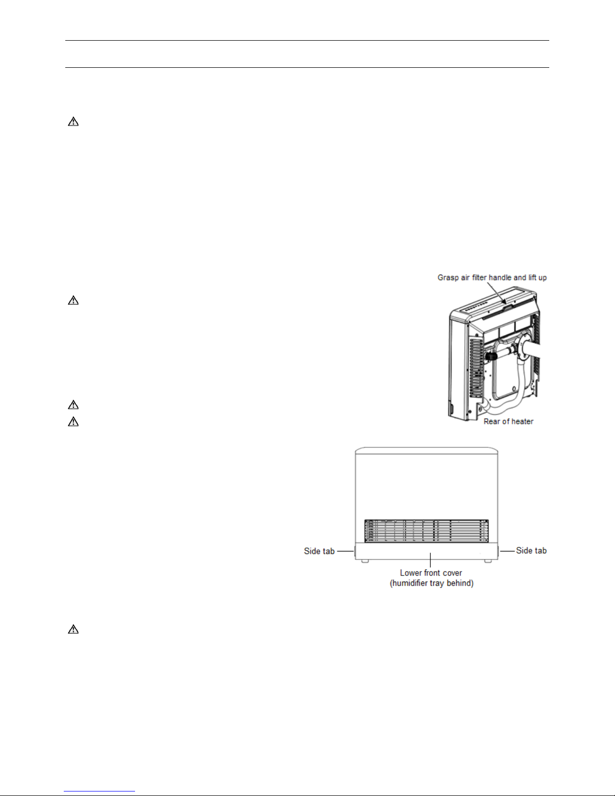
AIR FILTER REMOVAL
Warning: The heater must not be operated without the air filter. Turn
heater OFF before removing air filter.
To remove the air filter: The air filter is located on the top rear of the heater
and is removed by grasping the handle on top of the filter and lifting upwards.
To replace the air filter: Insert filter into slot on rear of heater and push fully
down into position.
HUMIDIFIER TRAY REMOVAL
Warning: Turn heater OFF before removing or replacing humidifier tray.
Warning: Do not overfill humidifier tray.
The humidifier tray is located on the bottom of the
heater and is accessed by rem oving the heaters front
lower cover.
To remove the humidifier tray: Simultaneously
depress tabs located on bottom of heater sides and pull
lower front cover away from heater. The humidifier tray
can then be removed b y carefully sliding out from the
heater.
To replace the humidifier tray: Reinsert humidifier
tray into heater tray receptacle and slide fully into
position. The lower front cover can then be replaced by
depressing cover tabs whilst sliding the cover into
position. Note: T he lower f ront co ver is universal i.e. it
does not matter which way is up.
SERVICING
Warning: Servicing must only be performed by authorised personnel.
For peak performanc e it is suggested that the he ater be serviced by your ne arest Rheem Service Dep artment or
Accredited Service Agent annually prior to every winter.
Only genuine replacement parts should be used on this heater.
Refer to “Service Proced ur es ” on page 30.
7
OPERATION
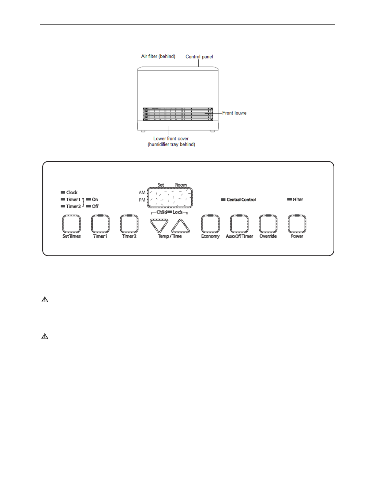
HEATER OVERVIEW
CONTROL PANEL OVERVIEW
Note: 'Central Control' LED is present on PRS-250CN and PRS-250CL commercial models only. Commercial
models also have a remot e Power LED and Filter LED located on th e top of the heater (refer to "Central Control
Connection & Operation – Commercial Models Only" on page 20).
TO TURN THE HEATER ON
Warning: DO NOT OPERATE THE HEATER IF THE FLUE SYSTEM IS NOT CONNECTED OR IF ANY PART
OF THE FLUE SYSTEM IS FAULTY OR DAMAGED. Operation of the heater without the flue system or with faulty or
damaged flue components may cause combustion pr oducts to be discharged into the room in which the heater is
located resulting in serious injury or death. If you smell strange odours, shut down the heater immediately and phone
your nearest Rheem Service department or Accredited Service Agent to arrange for an inspection.
Warning: If you smell gas do not attempt to turn on the heater.
• Switch on the electrical supply at the power point. The heater will perform a self check routine.
• After the self check routine ex pires , the heater can be t urned O N by pressing and releas ing th e hea ter ‘ Power’
button. The LED on the power button will illuminate green and the digital display will indicate the set temperature
and room temperature.
The heater will operate automatically when a call for heat occurs (provided the heater is not operating in a timed OFF
period) and the LED on the power button will change from green to red once ig nition has been succ essful. Note:
when first turned on the heater will operate in a pre warm cycle (burner on) for approximately 2 minutes regardless of
the set and room temperatures.
What to do if you smell gas?
• DO NOT try to light any gas appliance.
• DO NOT touch any electrical switch.
• TURN OFF the gas supply at the gas meter immediately, call your gas supplier or licensed gasfitter.
NOTE: Some gases are heavier than air and it may be necessary to check for gas leaks at floor level.
8

OPERATION
TO TURN THE HEATER OFF
• Turn the heater OFF by pressing and releasing the heater ‘Power’ button. T he burner, digital display and all
LED’s will extinguish ho wever the fan will co ntinue to operate f or a few minutes to cool do wn the heater and
prevent a build up of residual heat (fan run on). Note: The power supply should not be turned off during this cool
down period as this will prevent the fan from running on.
• The heater may be turned off at the power point when the heater fans stop operating.
RAISING OR LOWERING THE SET TEMPERATURE
The set temperature is the temperatur e setting the h eater will heat the room to. W hen the heater is tur ned ON, the
heater will automatically operate the burner to heat the room to the desired set temperature. When the room reaches
the set temperature the heater will automatically turn the burner OFF.
To Raise the Set Temperature: Press and release the ▲ button once to raise the set temperature by 1ºC. Each
consecutive press and release of the ▲ button will raise the set temperature in increments of 1ºC up to a maximum of
26ºC. Note: After 26ºC a 'H' s etting is available. The 'H' s etting is for Service procedures only and sho uld not be
selected. When setting the temperature to 'H' setting, the heater will monitor any abnormal high room air temperature
which is outside the normal temperature selection range. Should high room temperature be detected, the heater will
shut down and display error code 16 which will require the heater to be reset and the temperature setting changed to
a value from 16 ~ 26 (refer to “Fault Indication” on page 29).
To Lower the Set Temperature: Press and release the ▼ button once to lower the set temperature by 1ºC. Each
consecutive press and release of the ▼ button will lower the set temperature in increments of 1ºC down to a minimum
of 16ºC. Note: before 16ºC an 'L' setting is available. The 'L' setting is f or Servicing proced ures and should not b e
selected. If set on 'L' the heaters burner will not turn on at room temperatures above 10°C.
SETTIN G TH E TIME
The heater will operate without the time being set however timer function(s) will not operate. Set or change the time
as follows:
1. Press and release the ‘Set Times’ button once. --:-- (or a previo usly entered time) will appear on the digital
display and the 'Clock' LED and ‘AM or PM’ will illuminate green.
2. Press and hold down the ▲ or ▼ button. The display will change in 1 minute increments until the next hour is
reached at which t im e the displ ay wi ll then c han ge in 1 hour incr em ents until t he butt on is releas ed. When the
button is released the ▲ or ▼ button can then be pressed and release d to fine tune the time in 1 minute
increments.
3. When the correct time has been entered, press and release the ‘Set Times’ button 5 times to accept the setting.
The time will be saved and the display will revert to show the current set and room temperatures.
TIMER 1 & TIMER 2 OPERATION
Two on/off timers are available ( Timer 1 & Timer 2) and each tim er can be programm ed to automatically tu rn the
heater ON and OFF. For a tim er to operate, the actual time m ust be set, the timers ON and OFF tim es must be
programmed, the heaters ‘Power’ button must be turned on and the timer must be turned on (selected).
Note: PRS series room heaters have a pre-heat function that operates the burner up to one hour prior to the
programmed starting time of a timer to warm the room SO THAT THE ROO M REACHES THE REQUIRED
TEMPERATURE WHEN THE PROGRAMMED ON TIME IS REACHED. This pre-heat function is automatic and
will always occur when the heater is turned on and a timer has been programmed and selected.
Programming Timer 1 and/or Timer 2 operating Times
1. Press and release the ‘Set Times’ button twice to enter timer programming mode. The ‘Timer 1’ LED and ‘Timer
1 On’ LED will illuminate and the timer 1 ‘on time’ will be shown on the digital display.
2. To program Tim er 1 ‘on time’, press and hold down the ▲ or ▼ button. The display will change in 1 minute
increments until the next hour is reached at which time the display will then change in 1 hour increments until the
button is released. When the button is released the ▲ or ▼ button can then be pressed and released to fine tune
the time in 1 minute increments.
3. Press and release the ‘Set Times’ button once. The ‘Timer 1 Off’ LED will illuminate and the Timer 1 ‘off time’ will
be shown on the digital display. The Timer 1 ‘off time’ can now be programmed by operating the ▲ and ▼ arrow
buttons as previously explained in step 2.
4. Press and release the ‘Set T im es’ button once. The ‘Timer 2’ LED and ‘Timer 2 On’ LED will illuminate and the
Timer 2 ‘on time’ wil l be shown on th e digital di splay. The Timer 2 ‘on time’ can now be programmed by operating
the ▲ and ▼ arrow buttons as previously explained in step 2.
9

OPERATION
5. Press and release the ‘Set Times’ button once. The ‘Timer 2 Off’ LED will illuminate and the Timer 2 ‘off time’ will
be shown on the di gital displ ay. The Timer 2 ‘off time’ can now be programmed by operating the ▲ and ▼ arrow
buttons as previously explained in step 2.
6. Press and release the ‘Set T imes’ button once. This exits the Timer programming mode and the digital display
will revert to show the current set point and room temperatures.
It should be noted that tim er times are not required t o be programmed and the tim er programming mode can be
exited at any stage by pressing and releasing the ‘Set T imes’ button repeatedly until all timer On and Off LED’s are
extinguished. Also refer to 'Timer Programming Example' on page 10.
Turning Timer(s) ON (selecting a timer)
Before operating a timer ensure the relevant timer operating (ON & OFF) times have been programmed and that the
heater is turned on by pressing and releasing the ‘Power’ button. The set point temperature should be adjusted to the
required temperature and a check should be made to ensure there are no objects in front of the louver to block the air
outlet.
To turn a timer on, pres s and release the rele vant timer button(s) ( Timer 1 and/or Timer 2 can be selected). The
selected timer button LED will illuminate. Note: If the burner is operating the burner will turn off when a timer is turned
on unless the current t ime is within the progr ammed on time period ( including pre-heat period) in which case the
burner will continue to operate.
Up to one hour prior to the timers programmed ON time the burner will automatically turn on (pre-heat function); the
timer button LED will flash and the Power button LED will change from green to red upon successful ignition.
When the timers programmed OFF time is reached, the burner will turn off and the timer button LED will stop flashing
but remain on solid (as the timer is still se lect ed) . T he Power button wil l re vert from red to green when the b ur ner is
extinguished.
Notes:
• A timer cannot be selected unless it’s ON and OFF times have been correctly programmed.
• Although both timers can be selected, a second timer cannot be selected if it’s programmed ON time is within the
same programmed time period as the first timer.
Timer Programming Example
The following exam ple details how to set the timer 's to automatically operate the heater for a period during the
morning and another period during the evening:
Timer 1 ON at 6:00am (heater start at 5:00am to heat the room for 6:00am) and OFF at 9:00am.
Timer 2 ON at 5:00pm (heater start at 4:00pm to heat the room for 5:00pm) and OFF at 10:00pm.
1. Press and release the ‘Set Tim es’ button twice to enter timer programming mode.
2. Use the ▲ or ▼ buttons to adjust Timer 1 (morning) ON time to AM 6:00.
3. Press and release the ‘Set Tim es’ button once.
4. Use the ▲ or ▼ buttons to adjust Timer 1 (morning) OFF time to AM 9:00.
5. Press and release the ‘Set Tim es’ button once.
6. Use the ▲ or ▼ buttons to adjust Timer 2 (evening) ON time to PM 5:00.
7. Press and release the ‘Set Tim es’ button once.
8. Use the ▲ or ▼ buttons to adjust Timer 2 (evening) OFF time to PM 10:00.
9. Press and release the ‘Set Tim es’ button once to exit timer programming mode.
10. Use the ▲ or ▼ buttons to adjust the set temperature to the desired setting.
11. Press and release the ‘Power’ button to turn the heater on.
12. Press and release 'Timer 1' button to turn ON Timer 1.
13. Press and release 'Timer 2' button to turn ON Timer 2.
14. Ensure there are no objects in front of the louver to block the air outlet.
10

OPERATION
Turning Timer(s) OFF (deselecting a timer)
To deselect a timer, pres s and release t he selected t im er button (‘Timer 1’ or ‘Timer 2’ button). The relevant tim er
button LED will extinguish and th e burner will turn on (because the Power button is turned ON). Note: If a sec ond
timer was also se lected a nd the c urrent time was outs ide the t imers programm ed on per iod and pr e-heat time, t he
burner would not operate when the first timer is deselected.
Timer Over-Ride Function
The ‘Over ride’ butt on c an be op er ate d to tur n t he b urner off when the heater is o perati ng in a t imer on period or to
turn the burner on when the heater is operating in a timer off period.
• If a timer is selected and the heater is operating within a tim er programmed time period or pr e-heat period
(burner on), the timer m ay be over-ridden a nd the burner turne d off by pressin g and releasing th e ‘Over rid e’
button. The Over ride butto n LED will illum inate and flash and the P ower button LED will chang e from red to
green after the burner is extinguished.
If the ‘Over ride’ button is pres sed and rel eased onc e again, the Over ri de button LED will extingu ish and the
burner will operate pro vided the current time is within the selected timers programmed on period including
pre-heat period and provided the set temperature is higher than the room temperature.
• If a timer is selected and th e heat er is oper at ing o uts id e a timer programmed time period (burner off), the timer
may be over-ridden and th e burner turned on b y pressing and re leasing th e ‘Ov er ride’ butt on. T he Over ri de
button LED will illuminate and flash, the timer button LED will remain on and the burner will operate provided the
set temperature is higher than the room temperature.
If the ‘Over ride’ button is pressed and r eleased onc e again, the Over ri de button LED will extinguish and the
burner will turn off provided the current t ime is not within th e selected tim ers program med on period inc luding
pre-heat period.
AUTO OFF TIMER OPERATION
The Auto Off Timer can be activated so that the heater will automatically turn OFF after a preset time period.
1. Press and release the ‘Power’ button to turn the heater on.
2. Press and release the ‘Auto Off Timer’ button. 1h (1 hour) will be shown of the display and the Auto Off Timer
button LED will il luminate.
3. Each consecutive press and release of the ‘Auto Off Timer’ button will change the OFF tim e setting up to a
maximum of 12h (12 hours).
After a 5 second delay the display will start count ing down in hours and minutes and the Auto Off Tim er butto n LED
will flash. When the counter reaches zero the heater will automatically turn OFF and all LED's will extinguish.
Notes:
• Possible time settings are 1h, 2h, 3h, 4h, 5h, 6h, 7h, 8h, 10h & 12h.
• The set temperature m ust be higher than the r oom temperature for the burner to operate. Note: W hen first
turned ON the bur ner will oper ate for a period of a pproxim ately three m inutes regardl ess of the room and s et
temperatures.
ECONOMY MODE
Economy mode is designed to increase the efficiency of the heater.
To activate economy mode: Press and release the ‘Economy’ button. The LED on the economy button will
illuminate green and the heater will operate as follows:
a) If the room temperature reaches the set temperature the economy program is activated and the set temperature
is automatically reduced by 1°C after a delay of 30 minutes.
b) The set temperature is automatically reduced by another 1ºC after another 30 minute delay.
This subtle reduction in temperature is not noticed by the user and the set temp is not altered on the display however
the efficiency of the heater is increased.
To deactivate economy mode: Press and release the ‘ Economy’ button. The LED on the economy button will
extinguish, the heater will exit econom y mode and the set temper ature will return to the displa yed set temperatur e
value.
11
 Loading...