

Page 1

Horizontal Vent Terminal Location
Outside Walls
INSTALLATION INSTRUCTIONS
C
V
F
V
B
D E
V
Fixed
Closed
Operable
L
H
V
B
Fixed
Closed
V
K
X
I
MM
V
Vent Terminal
X
Air Supply Inlet
Area Where Terminal is Not Permitted
Interior Wall
A
X
V
G
V
B
Operable
V
A J
B
V
Venting
37
Page 2

INSTALLATION INSTRUCTIONS
Venting for Direct-Vent Water Heater (cont.)
The following chart details the minimal dimensional information needed to determine the proper location of
the vent terminal for direct vent and outdoor tankless water heaters. See corresponding letter reference in
the illustration at left.
Venting
Location
A = Clearance above grade, veranda, porch,
deck, or balcony.
B = Clearance to window or door that may be
opened.
U.S. Installation
Requirements
12 in. (30 cm) above anticipated snow
level.
• 6 in. (15 cm) for water heaters less
than or equal to 10,000 Btuh (3 kW).
1
• 9 in. (23 cm) for water heaters greater
than 10,000 Btuh (3 kW) and less
than or equal to 50,000 Btuh (15 kW).
• 12 in. (30 cm) for water heaters
greater than 50,000 Btuh (15 kW).
C = Clearance to permanently closed window.
D = Vertical clearance to ventilated soffit lo-
cated above the terminal within a horizontal
distance of 2 ft. (61 cm) from the centerline
of the terminal.
E = Clearance to unventilated soffit.
F = Clearance to outside corner.
G = Clearance to corner.
H = Clearance to each side of centerline ex-
tended above meter/regulator assembly.
I = Clearance to service regulator vent outlet.
J = Clearance to nonmechanical air supply inlet
to the combustion air inlet to any building or
other appliance.
• 6 in. (15 cm) for water heaters less
than or equal to 10,000 Btuh (3 kW).
• 9 in. (23 cm) for water heaters greater
than 10,000 Btuh (3 kW) and less
than or equal to 50,000 Btuh (15 kW).
• 12 in. (30 cm) for water heaters
greater than 50,000 Btuh (15 kW).
K = Clearance to mechanical air supply inlet. 3 ft. (91 cm) above if within 10 ft. (3 m)
L = Clearance above paved sidewalk or paved
driveway located on public property.
M = Clearance under veranda, porch, deck, or
balcony.
1 In accordance with current ANSI Z223.1/NFPA 54 National Fuel Gas Code.
2 In accordance with current CSA B149.1 Installation Codes.
For clearances not specified in ANSI 223.1/NFPA 54 or CSA B149.1, one of the following shall be indicated:
a) A minimum clearance value determined by testing in accordance with section 2.20, or
b) A reference to the following footnote: “Clearance in accordance with local installation codes and the requirements of the
gas supplier.”
†
A vent shall not terminate directly above a sidewalk or paved driveway that is located between two single-family dwellings and
serves both dwellings.
horizontally.
Not Allowed Not Allowed
Canadian Installation
Requirements
12 in. (30 cm) above anticipated snow
level.
2
• 6 in. (15 cm) for water heaters less
than or equal to 10,000 Btuh (3 kW).
• 12 in. (30 cm) for water heaters
greater than 10,000 Btuh (3 kW) and
less than or equal to 100,000 Btuh
(30 kW).
• 36 in. (91 cm) for water heaters
greater than 100,000 Btuh (30 kW).
3 ft. (91 cm) within a height of 15 ft.
(4,57 m) above the meter/regulator
assembly.
3 ft. (91 cm)
• 6 in. (15 cm) for water heaters less
than or equal to 10,000 Btuh (3 kW).
• 12 in. (30 cm) for water heaters
greater than 10,000 Btuh (3 kW) and
less than or equal to 100,000 Btuh
(30 kW).
• 36 in. (91 cm) for water heaters
greater than 100,000 Btuh (30 kW).
6 ft. (1,83 m)
7 ft. (2,13 m)
†
38
Page 3

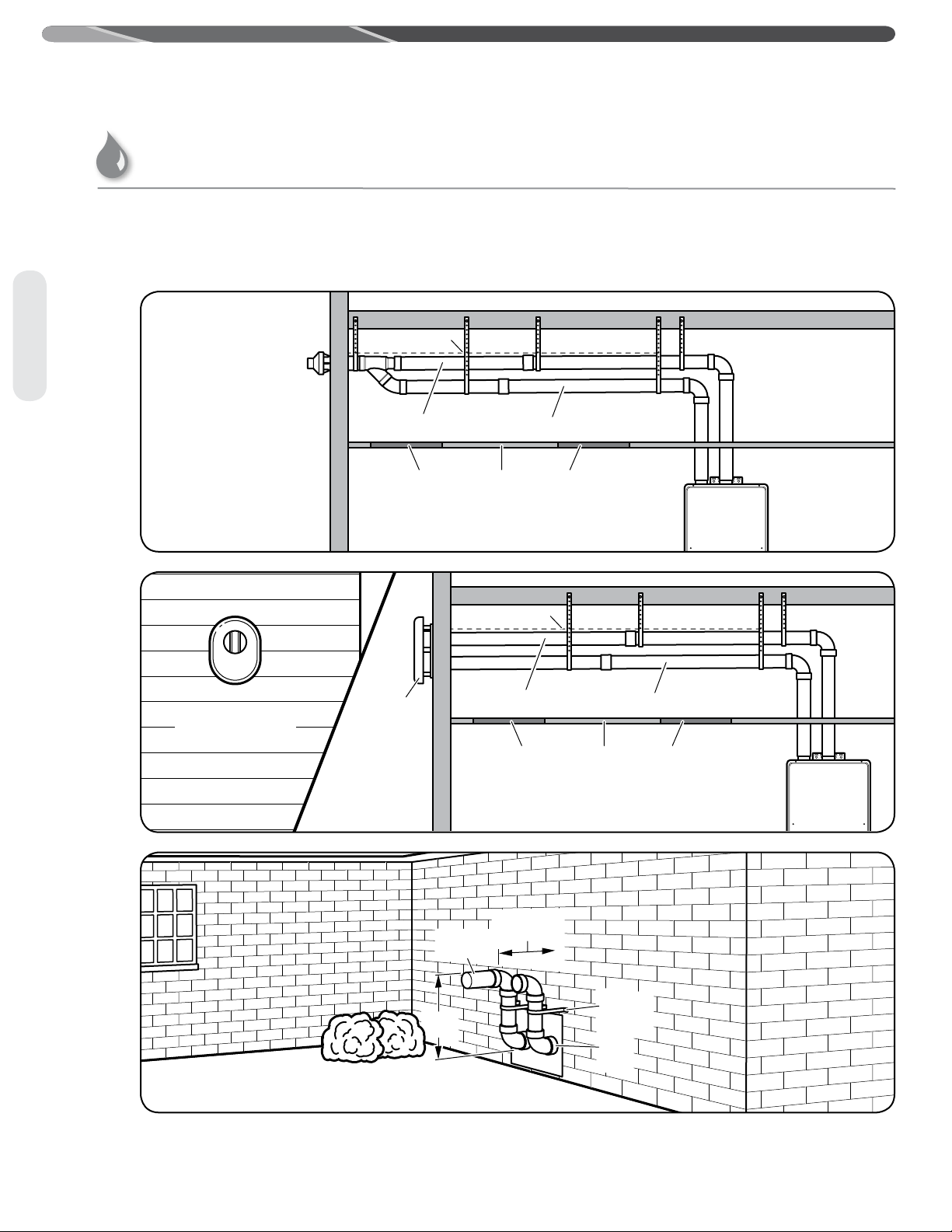
Horizontal Vent Considerations
Rising moisture will collect under eaves.
Inside
Corner
Caulk
Caulk
Caulk
Caulk
If soft vent is too close,
block off and install new
vent at another location.
6' (1.8 m) Caulk zone or
to edge of window etc.,
starting within 6' (1.8 m)
4'
(1.2 m)
Rising moisture will collect under eaves.
Inside
Corner
Caulk
Caulk
Caulk
If soft vent is too close,
block off and install new
vent at another location.
6' (1.8 m) Caulk zone
or to edge of window
etc., starting within
6' (1.8 m)
4'
(1.2 m)
12"
(300 mm)
WARNING: Moisture in the flue gas
will condense as it leaves the vent terminal. In cold
weather this condensate can freeze on the exterior
wall, under the eaves, and on surrounding objects.
Some discoloration to the exterior of the building
is to be expected. However, improper location
or installation can result in severe damage to the
structure or exterior finish of the building.
– Do not install vent terminals under any patio or
deck.
– Do not locate vent terminal on the side of a
building with prevailing winter winds. This will
help prevent water lines from freezing and
moisture from freezing on walls and under
eaves.
– Do not locate vent terminal too close to
shrubbery, since flue gases may damage them.
– All painted surfaces should be primed to
lessen the chance of physical damage. Painted
surfaces will require maintenance.
– Guard against accidental contact with people
and pets.
INDOOR TANKLESS WATER
HEATERS
WARNING: For multiple-unit
installation, a minimum distance between vent
terminations must be maintained to prevent
recirculation of vent gases. Maintain a centerto-center distance between each pair of vent
terminations of 24 in. (61 cm) for a two-unit
installation; 24 in. (61 cm) and 36 in. (91.4 cm) for
an installation of three units; and 24 in. (61 cm),
36 in. (91.4 cm), and 24 in. (61 cm) for an
installation of four units.
INSTALLATION INSTRUCTIONS
Venting
– Do not terminate vent directly on brick or
masonry surfaces. Use rust-resistant, sheetmetal backing plate of 1 sq. ft. (30 sq. cm)
behind the vent.
– Caulk all cracks, seams, and joints within
6 ft. (1.8 m) of the vent terminal.
– Caulk around wall faceplate for weather-tight
seal.
– Do not extend exposed vent pipe of indoor
water heaters outside of the building.
– This water heater requires its own separate
venting system. Do not connect the exhaust
vent to an existing vent pipe or chimney.
OUTDOOR TANKLESS WATER
HEATERS
– Install outdoor water heater such that air inlet
and flue outlet are above anticipated snow level.
39
Page 4
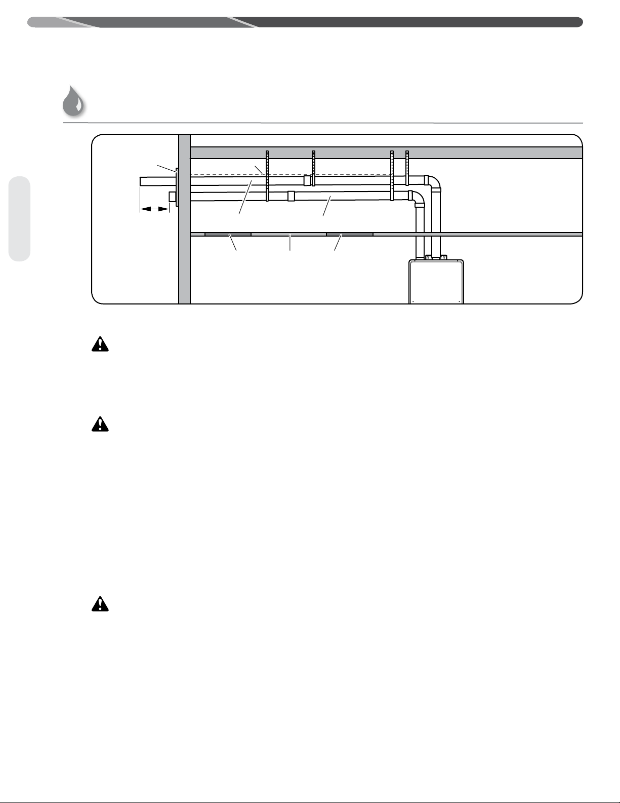
INSTALLATION INSTRUCTIONS
Exhaust Vent Pipe
Air Intake Pipe
Wall Plate
Inspection
Access Panel
(Optional)
Inspection
Access Panel
(Optional)
Ceiling
Downward Slope
12"
(300 mm)
Venting for Direct-Vent Water Heater (cont.)
Venting
40
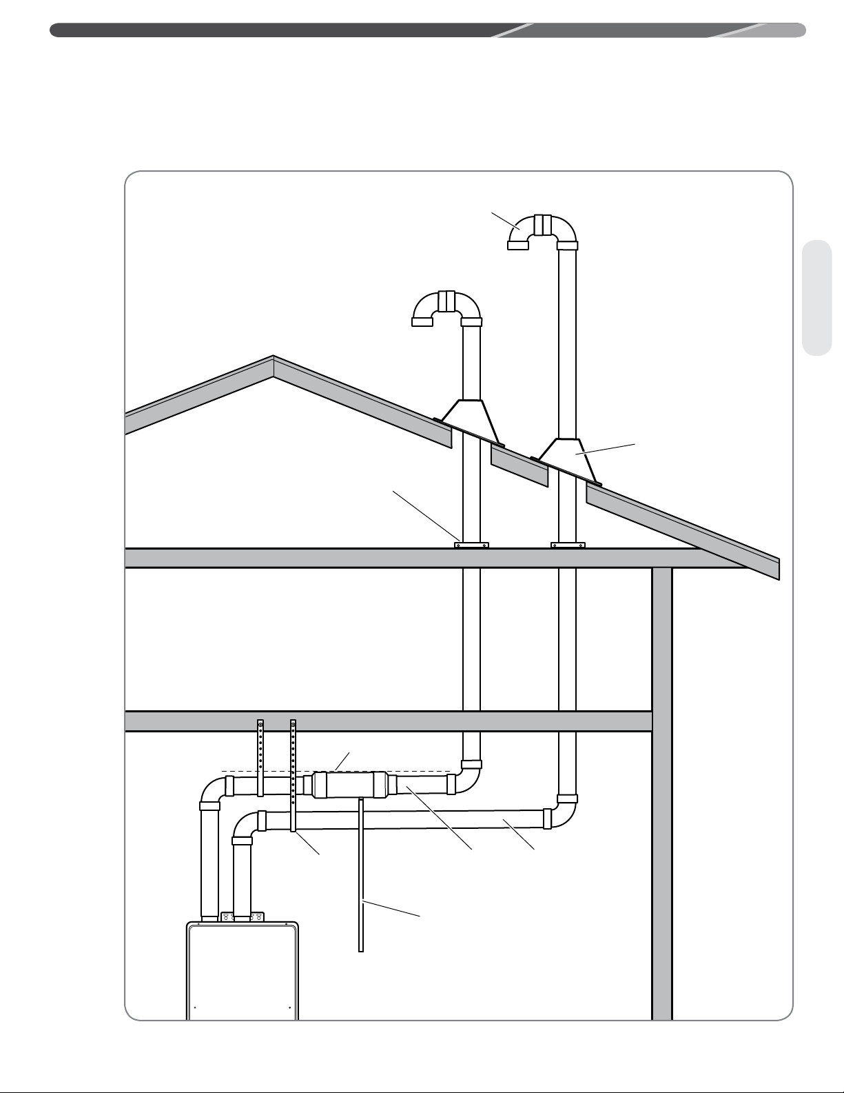
Horizontal Vent Installation
injury – Solvent cements and primers are highly
flammable. Provide adequate ventilation and do
not assemble near heat source or open flame. Do
not smoke. Avoid skin or eye contact. Observe all
cautions and warnings on material containers.
heater manufacturer-approved Schedule 40 PVC
(foam core is not permitted at any time), Schedule
80 PVC, CPVC, ABS polypropylene, or UL
1738-listed Category III Stainless Steel. No other
vent material is permitted.
Joining Pipes and Fittings
All pipe, fittings, solvent cement, primers, and
procedures, for the U.S., must conform to American
National Standards Institute and American Society
for Testing and Materials (ANSI/ASTM) standards.
For Canada, all pipe, fittings, solvent cement,
primers, and procedures must conform to ULCS636 and vent manufacture specifications.
• Do NOT use solvent cement that has become
curdled, lumpy, or thickened.
• Do NOT thin solvent cement. Observe shelf
precautions printed on the containers.
• For applications below 32°F, use only lower
temperature-type solvent cement.
• Appropriate solvent and cleaner must be used
for the type of vent pipe used (PVC, CPVC, or
ABS).
WARNING: Danger of fire or bodily
CAUTION: Use tankless water
CAUTIONS:
Cleaner-Primer and Medium-Body
Solvent Cement
All joints in vent piping must be properly sealed,
and we recommend using the following material:
PVC materials should use ASTM D-2564-grade
cement.
CPVC materials should use ASTM F-493-grade
cement.
ABS materials should use ASTM D-2235-grade
cement (ABS is not allowed in Canada).
Cementing Joints
1. Cut pipe end square; remove jagged edges and
burrs. Chamfer end of pipe; then clean fitting
socket and pipe joint area of all dirt, grease, or
moisture.
2. After checking pipe and socket for proper fit,
wipe socket and pipe with cleaner-primer. Apply
a liberal coat of primer to inside surface of
socket and outside of pipe.
3. Apply a thin coat of cement evenly in the
socket. Quickly apply a heavy coat of cement to
the pipe and insert pipe into fitting with a slight
twisting motion until it bottoms out.
4. Hold the pipe fitting for 30 seconds to prevent
the tapered socket from pushing the pipe out of
the fitting.
5. Wipe all excess cement from the joint with a
rag. Allow 15 minutes before handling. Cure
time will vary according to fit, temperature, and
humidity.
NOTICES:
• Cement must be fluid; if not, recoat.
• Stir the solvent frequently while using. Use a
natural bristle brush or the dauber supplied with
the can. The proper brush size is one inch.
Page 5
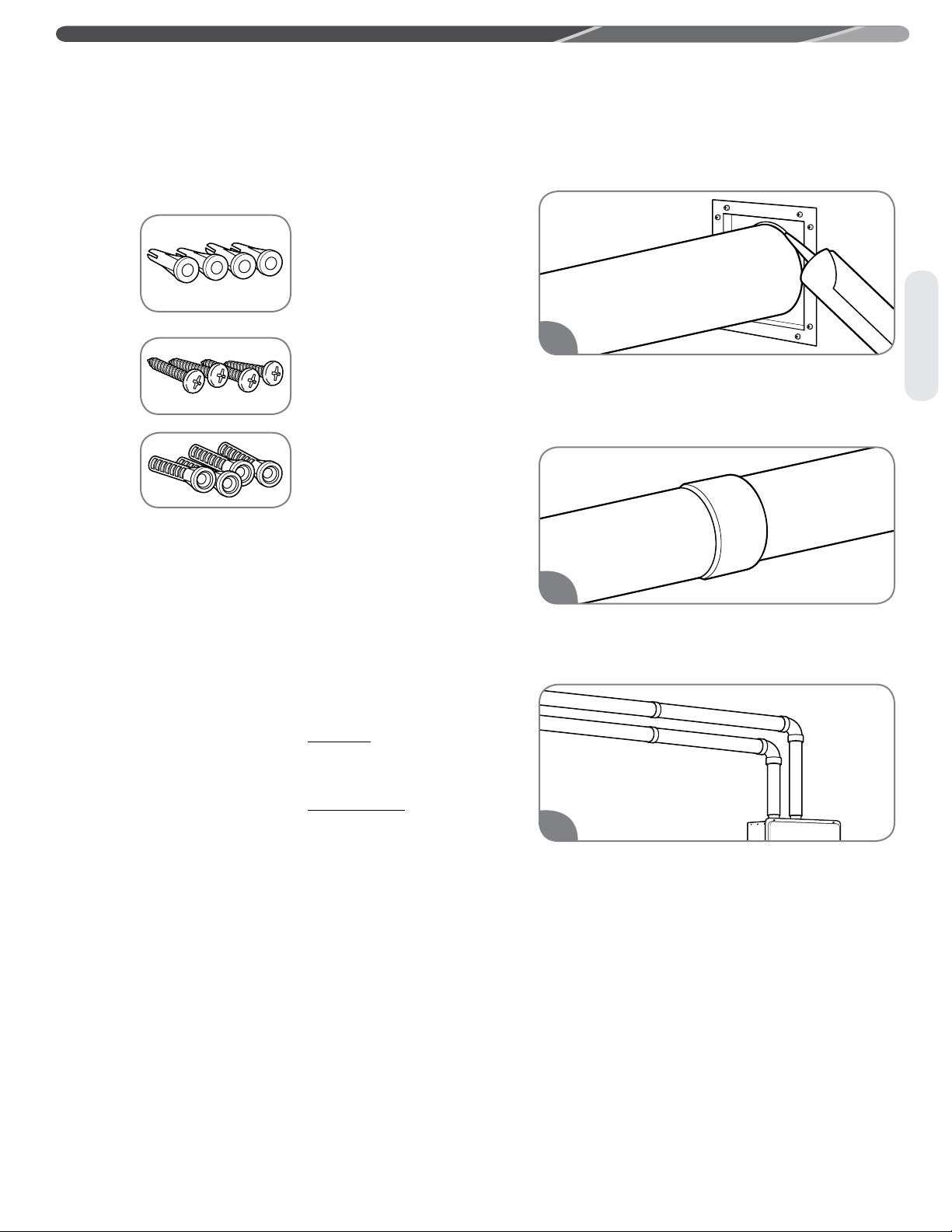
Horizontal Vent Installation (cont.)
Fasteners will vary depending on the wall type.
For particle board or
composite sheathing, use
4 hollow wall anchors. The
anchors should be at least
1/8 in. (0.3 cm) in diameter
and the appropriate length
for the sheathing thickness.
For plywood or solid
wood sheathing or
members, use 4 #10 x
1 1/4-in. wood screws.
For masonry walls, use
suitable masonry anchors
long enough to pass
through the wall.
NOTICES:
• The distance between the back edge of the
exhaust vent terminal and the exterior wall must
be 12 inches (30.5 cm) more for the exhaust vent
terminal than the air intake terminal.
• To prevent possibility of condensate freeze-up,
do not install vent kits one above the other.
Once the vent terminal location has been
determined, make holes through the exterior wall
to accommodate the vent pipes. Vent pipes must
exit exterior wall horizontally only.
The standard horizontal air intake termination is
a 2-inch or 3-inch pipe which terminates at the
exterior wall and uses a coupling to prevent the
pipe from being pushed back into the structure.
The standard horizontal exhaust outlet termination
is a 2-inch or 3-inch pipe which terminates 12
inches from the air intake termination. Insert a
small length of vent pipe through the wall and
connect the coupling. Connect vent cap or terminal
to the vent pipe on the exterior of the building.
1. Use the vent plate as a template to locate air
intake holes and four mounting holes. Observe
minimum clearances. Vent terminals must be a
minimum of 5.5 inches (14 cm) and a maximum
of 24 inches (61 cm) apart horizontally.
2. Cut two 2 1/2" (6.4 cm) diameter holes (for a
2" [5.1-cm] diameter pipe) or 3 1/2" (8.9 cm)
diameter holes (for a 3" [7.6-cm] diameter pipe)
for the exhaust vent and air intake openings.
Reinstall the decorative sheathing around the
faceplate. The decorative sheathing may be
painted to match the exterior decor.
INSTALLATION INSTRUCTIONS
1
Apply silicone sealant or silicone/latex caulk to
seal the vent pipe to the vent cap to permit field
disassembly for annual inspection and cleaning.
Completely seal where it passes through the wall
plate and where it is attached to the structure.
2
Attach the female end of the next vent pipe
section to the male end of the 2-in./3-in.
(5.1-cm/7.6-cm) vent pipe. See “Cementing
Joints” on page 40.
3
Complete the rest of the vent pipe installation to
the water heater’s flue outlet and air intake.
Venting
41
Page 6
INSTALLATION INSTRUCTIONS
Exhaust Vent Pipe
Air Intake Pipe
Inspection
Access Panel
(Optional)
Inspection
Access Panel
(Optional)
Ceiling
Downward Slope
Exhaust Vent Pipe
Air Intake Pipe
Wall Plate
Inspection
Access Panel
(Optional)
Inspection
Access Panel
(Optional)
Ceiling
Downward Slope
Air
Inlet
Exhaust
Outlet
Pipe
Support
Strap
24"
Max.
12"
From Wall
For information about termination kits, refer to "If You Need Service" on page 26, "Call for
Assistance" for the telephone number to speak to Customer Service Representative.
Venting for Direct-Vent Water Heater (cont.)
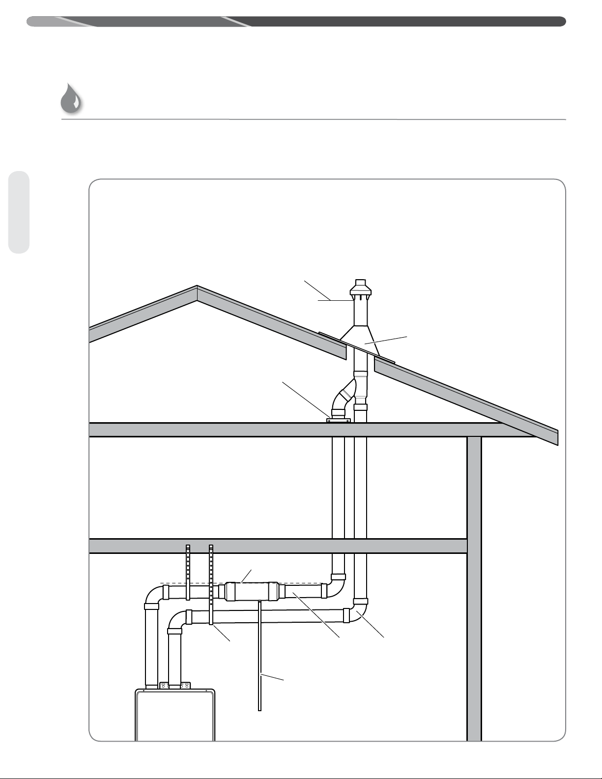
Alternative Horizontal Vent Installations
Alternative horizontal vent termination kits are commercially available. Please refer to the instruction sheet
packaged with the kit for complete installation instructions.
Venting
Concentric vent
termination kit
42
Flat horizontal
termination kit
Page 7
INSTALLATION INSTRUCTIONS
Hole
Through Roof
C
L
Hole
Through Ceiling
C
L
A, B, C, D
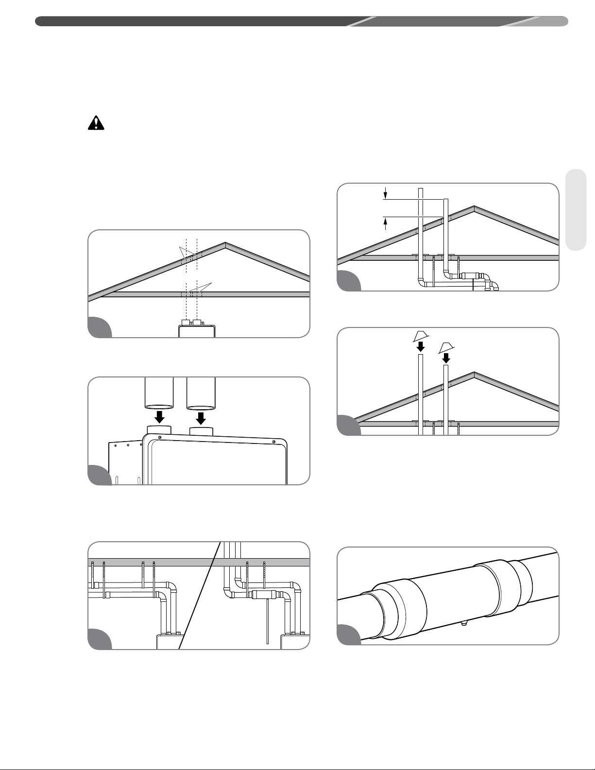
Vertical Vent Installation
WARNING: Improper vent
installation can result in death, personal injury,
product damage, and/or poor performance.
NOTICES:
• Only Rheem-approved termination and parts
should be used during installation.
• Maintain the recommended air space clearance
to combustible materials and building insulation.
1
Cut a hole through the roof and interior ceiling to
accommodate the vent pipes.
NOTICE: Free-standing vent pipe that
penetrates a roof/ceiling requires another means of
support from a second location.
Determine the vent terminal height and install
the vent pipe accordingly. Refer to “Vertical Vent
Terminal Location” on page 44 for clearance
requirements.
Venting
4
Install adequate flashing where the vent pipe
passes through the roof.
2
Complete the vent pipe installation to the water
heater’s vent connector fittings. Use cleanerprimer and PVC cement where the vent pipes
join the water heater.
3
Support vertical and horizontal runs as
described on page 35. Vertical supports are
required every 4 ft. (1.2 m) along a vertical pipe
route, after every transition to vertical, and after
every offset elbow.
5
Air Intake Condensate Trap
For vertical terminations or where the air intake
pipe slops down towards the water heater, it is
recommended to install a drain tee assembly. This
is to prevent any condensate or liquid water from
entering the intake of the water heater. Connect
the trap drain line to a suitable drain. Do not
connect it directly to the condensate drain line
from the water heater.
1
One trap method: Glue a 3” by 4” adapter
coupling to each end of a 4” PVC pipe length.
Drill a ½” hole in the side of the larger diameter
pipe. Tap and thread for a ½” barbed fitting,
install fitting. Install the collector with the fitting
facing down. Connect a drain hose to the fitting
and clamp, run hose to a suitable drain.
43
Page 8

A, B, C, D
12" Min.
(300 mm)
Vent Pipe
Through Roof
Optional
INSTALLATION INSTRUCTIONS
Venting for Direct-Vent Water Heater (cont.)
Vertical Vent Terminal Location
Venting
The following chart with diagrams details the minimum dimensional information needed to determine the
proper location of the vertical vent terminal for direct-vent indoor tankless water heaters:
U.S. Installation
Location
A = Minimum clearance above the roof level. 12 in. (30.5 cm) above roof level. 18 in. (45.7 cm) above roof level.
B = Minimum clearance above anticipated snow
level.
C = Maximum clearance above roof level (without
additional support for vent pipe).
D = Maximum clearance above anticipated snow
level (requires additional vent support).
E = Required vent clearance from any gable,
dormer, or other roof structure with building
interior access (i.e., vent, window).
F = Required vent clearance from any forced air
inlet, including dryer and furnace air inlets.
G = Minimum/maximum horizontal distance
between vent terminals
1 In accordance with current ANSI Z223.1/NFPA 54 National Fuel Gas Code.
2 In accordance with current CSA B149.1 Installation Codes.
The vertical intake air termination requires a
Requirements
12 in. (30.5 cm) above anticipated
snow level.
24 in. (61 cm) above roof level. 24 in. (61 cm) above roof level.
24 in. (61 cm) above anticipated snow
level.
4 ft. (1.2 m) 4 ft. (1.2 m)
10 ft. (3 m) 6 ft. (1.8 m)
5.5 in. (14 cm)/24 in. (61 cm) 5.5 in. (14 cm)/24 in. (61 cm)
1
Canadian Installation
Requirements
12 in. (30.5 cm) above anticipated
snow level.
24 in. (61 cm) above anticipated
snow level.
2
return bend or two short or long sweep radius 90°
elbows to keep the inlet downward and prevent
entry of rain. Refer to figure above for the proper
location of the air intake with respect to the
exhaust outlet termination. The vertical exhaust
outlet termination is a 2-inch or 3-inch pipe which
terminates at least 12 inches above the air intake
termination. The air intake and exhaust outlet
terminations must be at least 12 inches above the
roof line or anticipated snow levels.
44
Page 9
Adjustable Roof Flashing
Support Clamp
Upward Slope
Support Hanger
Air Intake
Pipe
Exhaust Vent
Pipe
Condensate
Drain
Optional
Standard Vertical Vent Termination
INSTALLATION INSTRUCTIONS
Venting
45
Page 10
Support Hanger
Adjustable Roof Flashing
Support Clamp
Upward Slope
Air Intake
Pipe
Exhaust Vent
Pipe
Minimum Clearance Above
Anticipated Snow Level
Condensate
Drain
INSTALLATION INSTRUCTIONS
Venting for Direct-Vent Water Heater (cont.)
Alternative Vertical Vent Termination
Alternative vertical vent termination kits are commercially available. Please refer to the instruction sheet
packaged with the kit for complete installation instructions.
Venting
46
Page 11

Water Supply
INSTALLATION INSTRUCTIONS
CAUTION: This water heater
MUST ONLY be used with the following water
supply conditions to prevent product damage and
operation failure.
• Clean, potable water free of corrosive chemicals,
sand, dirt, or other contaminates.
• Inlet water temperatures above 32°F (0°C), but
not exceeding 120°F (49°C).
• DO NOT reverse the HOT and COLD water
connections.
• DO NOT connect this water heater to water lines
previously used for space heating. All water
piping and components shall be suitable for
potable water.
• With recommended water quality (see chart).
Chart for Recommended Water Quality Levels
pH
6.5–8.5 Up to 500 mg/L Up to 15 mg/L
TDS (Total
Dissolved Solids)
Free Carbon
Dioxide (CO
)
2
Total
Hardness
Up to
200 mg/L
Aluminum Chlorides Copper Iron Manganese Zinc
0.2 mg/L
Up to
Thermal Expansion
A thermal expansion tank will be required if the
water heater is installed in a recirculation system.
This prevents damage to the heater, related piping,
and the relief valve.
NOTICE: Replacing the relief valve will
not correct the problem!
The expansion tank is designed with a built-in air
cushion that compresses as the system pressure
increases. This relieves the over-pressure condition
and eliminates the repeat operation of the relief
valve.
For other approved methods of thermal expansion,
contact an installing contractor, water supplier, or
plumbing inspector.
Up to
200 mg/L
Up to
1.0 mg/L
Up to
0.3 mg/L
Up to
0.05 mg/L
Up to
1.0 mg/L
Plumbing
Water Supply Connections
CAUTION: IMPORTANT—Do
not apply heat to the HOT or COLD water
connections. If sweat connections are used, sweat
tubing to the adapter before fitting the adapter
to the water connections on the water heater.
Any heat applied to the water supply fittings will
permanently damage the internal components of
the water heater.
NOTICE: In cold environments, ice can
accumulate in the water heater’s connectors. Plug
in the water heater power cord for approximately
10 minutes before making these connections. This
will melt any ice buildup.
Plumbing should be carried out by a qualified
plumbing contractor in accordance with local
codes.
Only use approved plumbing materials.
The minimum diameter of all water pipes should
be 3/4 in. (1.9 cm).
To conserve energy and to prevent freezing,
insulate both COLD and HOT water supply lines.
Do not insulate the drain line or pressure-relief
valve.
47
Page 12

INSTALLATION INSTRUCTIONS
Water Supply
Water Supply Connections (cont.)
Plumbing
To ensure proper operation of the water heater,
follow these water pressure guidelines.
• Operation of the water heater requires a
minimum water pressure of 14 psi (97 kPa) and a
minimum water flow rate of 0.4 gpm (1.5 lpm).
• Water pressure of 40 psi (276 kPa) is required to
achieve maximum flow rate.
• To maintain proper performance, there must be
sufficient water supply pressure.
Required Water Pressure =
Min. Operating Water Pressure
(14 psi [97 kPa])
+ Pipe Pressure Loss
+ Faucet Pressure Loss
+ Safety Margin
(more than 5 psi [34 kPa]).
Water Supply Installation
NOTICES:
• Use only Teflon tape on all COLD and HOT water
connections.
• If the water flow resistance of a showerhead is
too high, the burner in the water heater will fail to
ignite. Keep all showerheads clean from debris
that could cause additional pressure drop.
• If using mixing valves on the outlet, choose
one that prevents COLD water pressure from
overcoming HOT water pressure.
• If multiple water heaters are installed in a
manifold system, the water piping MUST be in
“parallel” and the water pressure at each water
heater should be 40 psi (276 kPa).
• To supply HOT water to upper floors, additional
water pressure will be required (0.44 psi [3 kPa]
per foot of height). Calculate the distance
between the water inlet of the water heater
(ground level) to the HOT water faucet farthest
away from the water heater (upper floor level).
• Well water systems should be set to ensure a
minimum system pressure of 40 psi (276 kPa).
The pressure should remain constant and stable
during the operation of the water heater.
• Gravity water pressure is not recommended.
When the water is supplied from a water supply
tank, the height of the tank, the diameter of the
supply pipes, and their relation to water pressure
need to be taken into consideration.
2
Before attaching the water line to the water
heater, open the shut-off valve. Run the water
until it has purged all contaminants (sand,
debris, air, caulking, etc.).
48
1
Install a COLD water shut-off valve near the
inlet line on the water heater. This valve will be
used for servicing and draining purposes.
NOTICE: It is not recommended to
use pipes with smaller diameters than the water
supply connection of the water heater.
3
Install a service valve on the end of the COLD
water supply line and connect it to the water
inlet on the water heater.
Page 13

Pressure
Relief Valve
Pressure
Relief Valve
Cold Water
Service Valve
Cold Water
Service Valve
Water
Inlet
Water
Inlet
Water
Outlet
Water
Outlet
Hot Water
Service Valve
Hot Water
Service Valve
Drain
Drain
Water Supply Installation (cont.)
4
Open the shut-off valve in the COLD water Inlet
line to check the water flow through the water
heater.
INSTALLATION INSTRUCTIONS
NOTICES:
• Be sure to connect the COLD water inlet and the
HOT water outlet as shown on the water heater.
If reversed, the water heater will not function.
• The flow rate of HOT water may vary when more
than two faucets (appliances, fixtures, etc.) are
being used simultaneously.
• The pipes MUST be completely drainable. If the
HOT water faucets are located at a point higher
than the water heater, place a drain valve at the
lowest point.
Plumbing
5
Close the shut-off valve and remove, clean, and
replace the water filter.
It is recommended to use unions and flexible
copper connections at the COLD and HOT
water lines. They allow the water heater to be
disconnected easily for servicing.
Use the following guidelines when connecting
the HOT WATER OUTLET:
• Connections between the water heater and
point(s) of use should be as short as possible.
• Local codes shall govern the piping used for
water connections.
• To conserve energy and to prevent freezing,
insulate both COLD and HOT water supply lines.
Do not insulate drain line or pressure-relief valve.
Water Piping Arrangement With Service Valve Kit
Service valve kits are available on all tankless
water heater systems. All kits include two full-port
isolation valves to be used in the COLD and HOT
water lines. When installed, these valves allow
one person full diagnostic testing and ease of
flushing the system. Contact your distributor or
place of purchase for availability and installation
information.
49
Page 14

INSTALLATION INSTRUCTIONS
Relief
Valve
Union
Union
Cold Water Supply
Shut-Off Valve
Cold Water
Supply Inlet
Hot Water
Supply Outlet
Relief Valve
Discharge Line
Water Supply (cont.)
Plumbing
Relief Valve
A new pressure-relief valve, complying with the
Standard for Relief Valves and Automatic Gas
Shut-Off Devices for Hot Water Supply Systems,
ANSI Z21.22/CSA 4.4, must be installed at the
HOT water outlet connection of the water heater
during installation. Local codes shall govern the
installation of any relief valves or place of purchase
for availability and installation information.
NOTICES:
• The following drawing illustrates a pressure-only
relief valve. If local codes require a combination
temperature and pressure-relief valve, you may
need to install an extension piece to ensure that
the valve probe is not directly in the flow path of
the water.
•
If local codes require that a temperature and
pressure-relief valve be installed, the manufacturer
recommends a type 40XL Watts temperature and
pressure-relief valve or equivalent model be used.
• Manual operation of relief valves should be
performed at least once a year.
• If the relief valve on the system discharges
periodically, a problem exists. Turn off the water
heater, unplug the unit, and call for service.
For safe operation of the water heater, be sure
that:
• The pressure rating of the relief valve must not
exceed 150 psi (1,034 kPa) or the maximum
working pressure of the water heater. (See the
rating plate on the water heater.)
• The BTUH rating of the relief valve must equal or
exceed the BTUH input of the water heater. (See
the rating plate on the water heater.)
• No valve of any type should be installed between
the relief valve and the water heater.
• Discharge from the relief valve should be piped
to a suitable drain. Piping used should be of a
type approved for the distribution of hot water.
• HOT and COLD water lines should be insulated
up to the water heater. See page 51.
• The discharge line must be NO SMALLER than
the outlet of the relief valve. The drain line must
pitch downward to allow for complete drainage
of the line and the valve.
• The end of the discharge line should not be
threaded or concealed and should be protected
from freezing. No valve of any type, restriction,
or reducer coupling should be installed in the
discharge line.
50
One end of the relief valve discharge line connects
to the HOT water outlet pipe as shown above.
The other end of the pipe should be routed to a
suitable drain to eliminate potential water damage.
Page 15

Hot and Cold Pipe Insulation Installation
Cold Water
Service Valve
Hot Water
Service Valve
Pressure
Relief Valve
Pressure
Relief Valve
Water
Outlet
Water
Outlet
Water
Inlet
Water
Inlet
Drain
Drain
Condensate Drain
INSTALLATION INSTRUCTIONS
WARNINGS:
• When pipe insulation is not rated for the
appropriate weather conditions, install electric
heat tracing or equivalent to prevent freezing of
the pipes.
• Do not insulate or block drain valve on the hot
outlet fitting.
• If pipes are allowed to freeze, the water heater
and the pipes may malfunction or leak due to
freezing water.
NOTICE: The hot and cold water supply
pipes should be insulated to provide additional
freeze protection.
Condensate
Condensate Drainage
Be sure the condensate runs freely to a drain and
does not accumulate inside the water heater. In
cold climates, precautions may need to be taken to
ensure that the condensate drain does not freeze.
• All condensation must drain and dispose of per
local code.
• If the condensate drain gets blocked, an error
code will display on the remote control. If this
occurs, the condensate drain must be cleared.
• Use only PVC or CPVC pipe or flexible tube for
the condensate drain line.
For increased energy efficiency, use pipe insulation
as shown in the diagram. Insulate the pipes all
the way to the top. DO NOT cover any drain or
pressure-relief valve(s).
Plumbing
• The drain pipe (along its entire length) must be at
least the same diameter as the drain line.
• The drain line should be as short as possible and
have a downward slope toward the end.
• The end of the drain pipe should be open to the
atmosphere. The end should not be under water
or other substances.
• Do not connect the drain pipe directly to the
drain sewer.
• Do not connect the drain pipe with an airconditioning evaporator coil drain.
51
Page 16

INSTALLATION INSTRUCTIONS
Union
Manual Gas
Supply Line
Shut-Off Valve
Cap
Sediment Trap
Manual Gas
Shut-Off Valve
Gas Supply
Gas Supply
Gas Supply Connections
WARNING: Do not attempt to
convert this water heater for use with a different
type of gas other than the type shown on the
rating plate. Doing so could result in death,
personal injury, explosion or fire, product damage,
and/or poor operating conditions or performance.
NOTICES:
• Gas piping shall be in accordance with local
utility company requirements and/or in the
absence of local codes, use the latest edition of
National Fuel Gas Code (NFGC), ANSI Z223.1.
In Canada, use the latest edition of CSA B149.1,
National Gas and Propane installation code.
• Apply a thin coat of pipe compound to all
threaded male ends. Compound must be of the
type resistant to the action of LP gas.
• To ensure proper water heater operation, the gas
pipe and gas meter must be sized correctly.
• If flexible connectors are used, the minimum
inside diameter must be 3/4" or greater and the
rated capacity of the connector must be equal
to or greater than the BTU capacity of the water
heater. See manufacturer information for the
gas connector. Lengths over 36 inches are not
recommended.
• Do not use excessive force (over 31.5 ft. lbs.
[42,7 Nm]) when tightening the pipe sections.
Excessive force can damage the water heater,
especially when Teflon pipe compound is used.
52
Page 17

INSTALLATION INSTRUCTIONS
Gas Piping
Pipe-Sizing Procedure – Example
The gas supply must be capable of handling the
entire gas load at the location. Gas line sizing
is based on gas type, the pressure drop in the
system, the gas pressure supplied, and gas line
type. For gas pipe sizing in the United States,
refer to the National Fuel Gas Code, NFPA 54. For
Canadian gas pipe sizing, refer to the Natural Gas
and Propane Installation Code CAN/CSA B149.1.
The information below is provided as an example.
The appropriate table from the applicable code
must be used.
1. Determine the cubic feet per hour of gas
required by dividing the gas input (on the rating
plate) by the heating value of the gas (available
from the local gas company). The gas input
needs to include all gas products at the location
and the maximum BTU usage at full load when
all gas products are in use.
Gas Input of
Cubic Feet Water Heater (BTU/HR)
Per Hour (CFH) = Heating Value of Gas (BTU/FT
2. Use the table for your gas type to find the pipe
size required for your cubic feet per hour of gas
and your pipe length.
Example: The heating value of propane gas for
3
your location is 2500 BTU/FT
. The gas input
of the tankless water heater is 199,900 BTU/
HR. Additional appliances at the location require
75,000 BTU/HR. Therefore, the cubic feet per
hour = (199,900 + 75,000)/2500 = 109 FT3/HR.
If the pipe length is 100 ft., then the 3/4-inch
pipe size capable of supplying 197 FT3/HR of
propane gas will be adequate.
Gas Supply
3
)
Pipe-Sizing Table – Natural Gas
Schedule 40 Metallic Pipe
Inlet Pressure: Less than 2 psi (55 inches W.C.)
Length
10
20
30
40
50
60
70
80
90
100
125
150
175
200
Refer to current National Fuel Gas Code, NFPA 54.
Pressure Drop: 0.3 inches W.C.
Specific Gravity: 0.60
(Capacity in cubic feet per hour)
Pipe Size (inches)
3/4 1 1 1/4 1 1/2
273 514 1060 1580
188 353 726 1090
151 284 583 873
129 243 499 747
114 215 442 662
104 195 400 600
95 179 368 552
89 167 343 514
83 157 322 482
79 148 304 455
70 131 269 403
63 119 244 366
58 109 224 336
54 102 209 313
Pipe-Sizing Table – Propane Gas
Schedule 40 Metallic Pipe
Inlet Pressure: 11.0 inches W.C.
Pressure Drop: 0.5 inches W.C.
Specific Gravity: 1.50
(Capacity in cubic feet per hour)
Length
10
20
30
40
50
60
80
100
125
150
175
200
1/2 3/4 1 1 1/4
291 608 1150 2350
200 418 787 1620
160 336 632 1300
137 287 541 1110
122 255 480 985
110 231 434 892
101 212 400 821
94 197 372 763
89 185 349 716
84 175 330 677
74 155 292 600
67 140 265 543
Pipe Size (inches)
53
Page 18

INSTALLATION INSTRUCTIONS
Gas Supply (cont.)
Gas Supply Installation
4
Gas Supply
1
Install the manual gas appliance shut-off valve
to the gas connection at the water heater. The
shut-off is supplied with the water heater.
2
Install a ground joint union or ANSI design-
certified semi-rigid or flexible gas appliance
connector to the open end of the manual gas
appliance shut-off valve. The (NFGC) ANSI
Z223.1 and CSA B149.1 codes mandate the
use of manual gas shut-off valves.
Using the proper-size piping, fittings, and
components, build the gas supply line to the
water heater.
NOTICE: The gas supply line should
be a minimum of 3/4-in. (1.9-cm) black steel
pipe or other approved gas piping material.
5
Install a sediment trap at the lowest portion of
the gas line.
The inlet gas pressure to the water heater must
NOT exceed 10.5 in. w.c. (2.6 kPa) for natural
gas and 14 in. w.c. (3.5 kPa) for LP gas. For
purposes of input adjustment, the minimum inlet
gas pressure (with main burner on) is shown on
the water heater rating plate. If high or low gas
pressures are present, contact your gas supplier
for correction.
54
3
Install a manual gas supply line shut-off valve
to the end of the gas supply line.
NOTICE: Lever-type gas shut-offs
should all be T-handle type.
Page 19

Leak Testing
WARNING: Never use an open
flame to test for gas leaks, because death,
personal injury, and/or property damage can result.
The water heater and its gas connections MUST
be leak-tested at normal operating pressures
before the unit is placed in operation. These tests
should also include all factory connections.
INSTALLATION INSTRUCTIONS
Turn on the gas shut-off valve(s) to the water
heater.
Use a soapy water solution to test for leaks at all
the connections and fittings. If bubbles are seen,
it indicates a gas leak that must be corrected.
Contact a qualified service technician.
Pressure Testing the Gas Supply
System
CAUTION: Install a gas pressure
regulator in the gas supply line. This regulator
should not exceed the maximum supply pressure.
DO NOT use an industrial-type gas regulator.
Gas Supply
The water heater and its manual gas shut-off valve
must be disconnected from the gas supply piping
system whenever the pressure testing will exceed
1/2 psi (14 in. w.c. [3.5 kPa]).
The water heater must be isolated from the gas
piping system whenever the pressure testing
will be less than and/or up to 1/2 psi (14 in. w.c.
[3.5 kPa]). Closing the manual gas shut-off valve
will isolate the water heater from the gas piping
system.
55
Page 20

INSTALLATION INSTRUCTIONS
Gas Supply (cont.)
Gas Supply
Electrical
56
High-Altitude Installation
The water heater is certified for installations up
to 3,280 ft. (1,000 m) above sea level. The input
rating of this water heater is based on sea level
operation. At higher elevations, the actual input
rate may be lower than the value listed on the
rating label.
Electrical Wiring
DANGER: Shock Hazard – Before
servicing the water heater, turn off the electrical
power to the water heater at the main disconnect
or circuit breaker. Failure to do so will result in
death or serious personal injury.
WARNING: Field wiring connections
and electrical grounding must comply with local
codes or, in the absence of local codes, with the
latest edition of the National Electrical Code, ANSI/
NFPA 70, in the U.S., or Canadian Electrical Code,
CSA C22.1, Part 1, in Canada.
CAUTION:
disconnecting. Wiring errors can cause personal
injury, product damage, and/or dangerous operating
conditions. Verify correct operation after servicing.
Label all wires prior to
NOTICES:
• Do not connect power until venting installation is
complete (see Venting Installation pages 34–46).
• Wait ninety (90) seconds after power is
connected for the first time to initiate operation
of the water heater.
Power Cord
• The electric power supply requirement for this
water heater is 120 VAC/60 Hz, 2 amps.
• A dedicated circuit is recommended for the water
heater. Do not connect to a GFCI or AFCI circuit.
Multiple units may be connected to a single
circuit up to the circuit rating.
• Do not use 3-prong to 2-prong adapters. Do not
use power strips or multiple outlet adapters.
NOTICES:
• For installations above 3,280 ft. (1,000 m)
elevation, contact a qualified service technician
to make the proper altitude adjustments. See
pages 67 and 68 for additional information.
• Do not install this water heater at elevations
above 3,280 ft. (1,000 m) without the proper
adjustments. Please contact your installer, local
gas supplier, place of purchase, or the Rheem
Customer Service phone number listed on
page 26 in the “Call for Assistance” section.
• All direct-vent gas models come with a threeprong power cord. Only use this power cord and
a matching grounded electrical outlet.
• All outdoor gas models do not come with a
power cord. Only hard-wire to an appropriate
power outlet with a ground terminal.
• Keep any excess length of the power supply
cord on the outside of the water heater.
• If local codes require hard-wiring, see
instructions for “Hard-Wiring the Electrical
Connections” below.
Hard-Wiring the Electrical Connections
• Wiring should be performed by a qualified
electrician in accordance with local codes.
• The water heater requires a properly grounded
120 VAC/60 Hz dedicated power supply. Multiple
water heaters may be connected to a single
circuit up to that circuit’s rating.
•
DO NOT connect grounding wire to water pipes,
gas pipes, telephone cables, lighting conductor
circuits, or to any other grounding circuits that
require a GFCI or AFCI (arc fault circuit interrupter).
• An ON/OFF switch must be provided and
installed for the incoming 120 VAC power supply.
• Wire the water heater exactly as shown in the
wiring diagram. This wiring diagram can also be
found inside the water heater cover panel.
• The green screw is provided in the enclosure for
a grounding connection.
• Connect the live wire to the black wire and
neutral wire to the white neutral wire.
Page 21

Wiring Diagram
W: WHITE, BLANC
BK: BLACK, NOIR
BR: BROWN, BRUN
BL: BLUE, BLEU
FOR INDOOR, DIRECT-VENT
GY: GRAY, GRIS
CODE DE COULEUR
COLOR CODE
R: RED, ROUGE
AMBIENT AIR
THERMISTOR
THERMISTOR
VERT/JAUNE
Y: YELLOW, JAUNE
G/Y: GREEN/ YELLOW,
O: ORANGE, ORANGE
G: GREEN, VERT
R4
FLAME ROD 1
ÉLECTRODE DE
DÉTECTION
DE FLAMME 1
MODEL ONLY
POUR MODÈLE INTÉRIEUR À
ÉVENT DIRECT SEULEMENT
HEAT EXCHANGER
THERMISTOR
D’ADMISSION D'EAU
WATER INLET
THERMISTOR
D’AIR AMBIANT
R3
BK
FLAME ROD 2
ÉLECTRODE DE
DÉTECTION
DE FLAMME 2
R2
BK
GAS TYPE
INSTALLATION INSTRUCTIONS
THERMISTOR
DE SORTIE D’EAU CHAUDE
HOT WATER OUTLET
THERMISTOR
THERMISTOR
D’ECHANGEUR DE CHALEUR
THERMISTOR
P.G.F.R VALVE
WATER VOLUME CONTROL MOTORWATER BY-PASS CONTROL MOTOR
MOTEUR DE CONTRÔLE DU VOLUME D’EAU
PSV
−
+
ÉLECTROVALVE DE DÉRIVATION D’EAU
CIRCUIT BOARD
PLAQUE DE CIRCUIT
R1
BK
IMPRIMÉ DE TYPE Â GAZ
MOTOR
MOTEUR
LIMITER
LIMITEUR
MOTOR
MOTEUR
LIMITER
LIMITEUR
GG BL BL
BK R Y O WBR
R Y O WBR
BK
CONTROL 2
BATH REMOTE
TÉLÉCOMMANDE 2
« BATH »
BATH REMOTE
CONTROL 1
TÉLÉCOMMANDE 1
« BATH »
MAIN REMOTE
CONTROL
TÉLÉCOMMANDE
« MAIN »
(USC2-117)
31-98419 2
(USC1-117)
(UMC-117)
8
8
NEUTRALIZER WATER
ON
MARCHE
LEVEL ELECTRODE
ÉLECTRODE DE NIVEAU
CONTACTEUR DIP 1
DIP SWITCH 1
ON
OFF
ARRÊT
4
3
2
1
R
R
D’EAU DE NEUTRALISANT
5
FAN MOTOR
DIP SWITCH 2
CONTACTEUR DIP 2
MARCHE
OFF
ARRÊT
4
3
2
1
YWR BK BL
FM
MOTEUR DU
VENTILATEUR
FOR DIRECT-VENT MODEL ONLY
BL
BOUTON DE RÉGLAGE
BOUTON MAX.
BOUTON MIN.
CIRCUIT BOARD
T
W
M
LED
PLAQUE DE CIRCUIT
SW3SW2SW1
MAX BUTTON ADJUSTER BUTTON
MIN BUTTON
1
2
P
G
123456
W BL R O Y
GND
BK
SV4
SV3
`
POUR MODELE À ÉVENT DIRECT SEULEMENT
SOLENOID VALVE 4
ÉLECTROVALVE 4
SOLENOID VALVE 3
ÉLECTROVALVE 3
SV2
SOLENOID VALVE 2
ÉLECTROVALVE 2
BK
A
4 3 2 1
F
G/Y
SV1
SOLENOID VALVE 1
2
345
USUALLY
DISCONNECTED
NORMALEMENT
K
R
5678
BK
W BK
BK
BK
SV0
ÉLECTROVALVE 1
ÉLECTROVALVE DANS
SOLENOID VALVE 0
1
DÉCONNECTÉ
G
W
BL
B
R
R
BK
BK
( )
123
4
567
YW
1
23
GY
4
BL
W
RÉSISTANCE
RESISTOR
ADMISSION DE GAZ
IG
BK
ELECTRODE
GY
GY
ALLUMEUR
IGNITER
ELECTRODE
Y
R
G
BL
BK
45678
R
Y
G
BK
8C9
BL
456
7
1
2
U
R
H
3
1
WW
2
4
W
W
ANTI-FROST HEATER
CHAUFFAGE ANTI-GIVRE
W
BL
O
W
BR
1
2
3
O
W
BR
1
2
3
3
2
1
BL
1
2
3
V
WATER FLOW SENSOR
CAPTEUR DE DÉBIT D’EAU
S
W
BR
W
BK
R
Electrical
IJ
W
W
W
W
BK
W
BK
W
BK
G/Y or G
AC
120V
FUSIBLE (3A)
FUSE (3A)
OVER HEAT LIMITER
GND
FOR INDOOR, DIRECT-VENT
LIMITEUR DE SURCHAUFFE
`
MODEL ONLY
POUR MODELE INTERIÉUR À
ÉVENT DIRECT SEULEMENT
57
Page 22

INSTALLATION INSTRUCTIONS
Electrical Wiring (cont.)
Remote Control Selection and
Location
WARNING: Field wiring connections
and electrical grounding must comply with local
codes or, in the absence of local codes, with the
latest edition of the National Electrical Code, ANSI/
NFPA 70, in the U.S., or Canadian Electrical Code,
CSA C22.1, Part 1, in Canada.
NOTICES:
•
The provided remote control will allow maximum
temperature settings of 120°F (49°C). Temperatures
up to 140°F (60°C) for residential applications and
up to 185°F (85°C) for commercial applications*
can be achieved with the MAIN (UMC-117) remote
control. Only qualified service personnel should
perform this adjustment.
• An optional cable (EZ Link
CableTM) can be purchased
separately to manifold two
water heaters together.
• Do not attempt to disassemble
a remote control. All controls are
sealed and calibrated for accurate
water heater control and operation.
Review the following considerations before
determining the location of the remote
control(s):
• Do not install any remote control
outdoors or where it can come in
contact with water.
Avoid installing the remote control in
•
the following areas and/or conditions:
– area exposed to heat.
– area exposed to steam.
– area exposed to oil.
– area exposed to direct sunlight.
– areas near stored or used
flammable products.
• Place remote control out of children’s reach.
• The remote control should be installed in a
convenient location (e.g., kitchen, laundry room,
utility room, or directly next to the water heater).
• The maximum distance between the water
heater and the remote control installation
location is limited to 195 ft. (59 m) of wire.
Electrical
58
One remote control is provided with the water
heater. Additional remote controls may be
purchased separately. The available remote
controls are listed in the following chart. Up to
three remote controls can be used with the water
heater. No other manufacturer’s controls are
suitable for use with this water heater.
Remote Control
Model Number
UMC-117 MAIN
USC1-117
USC2-117 BATH 2
MIC-6 or MIC-185**
Manifold System
*A commercial conversion kit can be purchased to achieve temperatures up to 185°F (85°C).
**When a manifold system is installed, the main remote control connected to the manifold controller
(MIC-6 or MIC-185) has priority over the remote controls connected to the water heater.
Remote Control
Description
BATH 1
Manifold System Optional (Sold Separately)
Temperature
Set Point Range Availability
100°F–120°F (38°C–49°C) Factory Default
85°F (29°C)
125°F–140°F (52°C–60°C)
85°F (29°C)
125°F–185°F (52°C–85°C)
100°F–120°F (38°C–49°C) Optional (Sold Separately)
85°F (29°C) Qualified Technician Adjustment
100°F–120°F (38°C–49°C) Optional (Sold Separately)
85°F (29°C) Qualified Technician Adjustment
Adjustment for Residential Products
Adjustment for Commercial Products*
Qualified Technician
Qualified Technician
Page 23

Remote Control Installation
WARNING: Field wiring connections
and electrical grounding must comply with local
codes or, in the absence of local codes, with the
latest edition of the National Electrical Code, ANSI/
NFPA 70, in the U.S., or Canadian Electrical Code,
CSA C22.1, Part 1, in Canada.
INSTALLATION INSTRUCTIONS
4
NOTICES:
• Remote control cable can be any Type–T 18
AWG wire similar to a thermostat wire and need
not be polarity-sensitive.
• It is not recommended to have wiring exposed.
• Do not apply sealant to remote control cable.
• Do not use network cable, telephone wire, or
any twisted-pair cable.
Connecting the MAIN (UMC-117) Remote
Control to a Wall:
1
Drill a 1- to 1 1/2-in. (2.5/3.8-cm) hole at the
proposed control location. Install the remote
control cable between the location of the
remote control and the water heater.
Install the base plate to the wall using suitable
screws and wall anchors.
NOTICE: The tabs on the base plate
should always point out.
5
Connect the remote control to the remote
control cable.
Electrical
6
Position the remote control on the base plate.
2
Remove the remote control from the base plate.
3
Feed the remote control cable through the large
center hole in the base plate.
NOTICE: The tabs on the base plate
should line up with the slots on the back of the
control panel.
Secure the control panel to the base plate with
one screw into the bottom tab.
NOTICE: Do not attempt to connect the
remote control or control wire to the water heater
while the water heater has power applied to it.
Damage to the water heater will occur. Do not
cut or strip the wiring while it is connected to the
water heater or while the water heater has power
applied to it.
59
Page 24

INSTALLATION INSTRUCTIONS
Remote Control
Connection Cover
Remote Control
Connection Cover
Electrical Wiring (cont.)
Connecting the Remote Control to the Water
Heater:
1
Ensure that the power to the water heater has
been disconnected.
4
Firmly tighten the terminal screws by hand.
Secure the remote control extension cable on
5
Electrical
2
Loosen the one screw located on the remote
control connection cover. The connection cover
is made of white plastic.
NOTICE: DO NOT REMOVE FRONT
PANEL. Remote control wires are connected on
the bottom of the unit.
There are no accessible remote control
terminals inside the water heater.
3
Connect the remote control extension cables
from the remote control to the remote control
connection terminals.
the hook located on the side of the remote
control connection base.
Reinstall the remote control connection cover
6
and secure with the one screw.
NOTICE: Do not connect power until
venting installation is complete.
Switch on the power supply to the water heater.
60
NOTICE: The remote control wire
connection terminals are not polarity-sensitive.
7
Check for proper operation of the remote
control and the water heater.
Page 25

Insulation Blankets
INSTALLATION INSTRUCTIONS
In general, insulation blankets for external use
on gas water heaters are not necessary. The
purpose of an insulation blanket is to reduce the
standby heat loss from the water heater’s storage
tank. Since these water heaters do not store water,
they eliminate the need for the insulation blanket.
WARNINGS:
• If local codes require the application of external
insulation blanket kits, carefully follow the
manufacturer’s installation instructions included
with the kit. Only use blanket kits that are
approved for use with your water heater.
• NEVER cover the air inlet, flue outlet, or
operating and warning labels attached to the
water heater. Operating and warning labels
should not be relocated to the exterior of an
insulation blanket. Covering these components
will cause dangerous operating conditions that
can lead to death, personal injury, property
damage, and/or product damage.
The manufacturer’s warranty does not cover any
damage or defect caused by insulation, insulation
attachment, or use of any type of energy-saving
or other unapproved devices (unless authorized
by the manufacturer). The use of unauthorized
energy-saving devices can result in death,
personal injury, and/or property damage. The
manufacturer disclaims any responsibility for
such loss or injury resulting from the use of such
unauthorized devices.
Installation Precautions
• Follow all installation instructions covered in this
manual.
• Check the inlet gas pressure to make sure it is
within the range specified on the rating plate.
• Make sure there is adequate air for combustion
and ventilation as described on pages 37–38 or
page 44 in this manual.
• Maintain proper clearances to combustibles and
noncombustibles as specified on the rating plate.
• Make sure the venting system complies with
local codes, National Fuel Gas Codes (ANSI
Z223.1/NFPA 54) or CSA B149.1, and the
guidelines found on pages 34 through 46 in this
manual.
Electrical
• Contact the local gas company to make sure the
gas meter and gas piping are adequately sized.
• Use only Teflon tape on all male water line
connections and fittings.
• Do not block or restrict any air intake openings.
• Do not remove the front cover unless absolutely
necessary. This should only be done by a
qualified service technician.
• Do not install this product where standing water
may occur.
• Do not use pipe dope on water line connections
and fittings.
61
Page 26

INSTALLATION INSTRUCTIONS
Installation Checklist
A. Water Heater Location
Indoor water heaters must be installed
indoors.
Outdoor water heaters must be installed
outdoors.
Close to area of ventilation termination
(indoor models).
Protected from freezing temperatures.
Proper clearance from combustible material
observed.
Sufficient fresh air supply for proper operation
of water heater.
Air supply free of corrosive elements and
flammable vapors.
Provisions made to protect area from water
damage.
Sufficient room to service heater.
C. Water Supply/Relief Valve
Water supply has sufficient pressure.
Air has been purged from the water heater
and the piping.
Water connections tight and free from leaks.
Water filter is clean and in place.
All piping has been assembled as described
on pages 48 and 49.
Water pipes are insulated and protected from
freezing, if necessary.
Pressure-relief valve properly installed with
discharge line running to open drain.
Discharge line protected from freezing, if
necessary.
D. Gas Supply
Gas type matches listing on rating plate.
Checklist
Combustible materials, such as clothing,
cleaning materials, and rags, clear of the
heater and vent piping.
Water heater is properly attached to the wall.
B. Vent (Indoor Models)
Vent pipe material is PVC and is
manufacturer-approved.
Horizontal air intake and exhaust pipes have
a 1/4" per foot DOWNWARD slope toward the
vent terminal.
Vertical venting is installed as described on
pages 43 and 44.
Connection(s) securely fastened together with
cement and airtight.
All vent runs are properly installed.
Vent terminal is properly installed.
Maximum vent length is observed.
Gas supply pressure is sufficient for the water
heater.
Gas line equipped with shut-off valve, union
and sediment trap as described on page 54.
Approved pipe-joint compound has been
used on all gas pipe connections.
All connections and fittings have been
checked for leaks with a soapy water
solution.
Gas company inspected installation (if
required).
E. Electrical Wiring
Supply cord and/or wiring meets all local
codes, National Electrical Code, ANSI/NFPA
70, in the U.S., or Canadian Electrical Code,
CSA C22.1, Part 1, in Canada.
Voltage matches listing on rating plate.
Water heater is properly grounded.
62
F. Condensate
Condensate drain is properly installed.
Page 27

Lighting the Water Heater
INSTALLATION INSTRUCTIONS
WARNING: Before operating
this water heater, be sure to read and follow
the instructions on the following label, all labels
on the water heater, and the “Important Safety
Information” section in this manual. Failure to
do so can result in unsafe operating conditions
that can result in death, personal injury, property
damage, and/or product damage.
NOTICE: If you have any problems
reading or following the instructions in this manual,
STOP and call a qualified service technician or
contractor.
FOR YOUR SAFETY READ BEFORE OPERATING
WARNING : If you do not follow these instructions exactly, a fire or explosion may result
causing property damage, personal injury or loss of life.
OPERATING INSTRUCTIONS
1.STOP! Read the safety information above on this label.
2.Turn off all electric power to the appliance.
3.Do not attempt to light the burner by hand.
4.Turn the Gas Shutoff Valve located on the outside of the unit
clockwise to the "OFF" position.
5.Wait five (5) minutes to clear out any gas. If you then smell gas, STOP! Follow "B" in
the safety information above on this label. If you don't smell gas, go to the next step.
6.Turn the Gas Shutoff Valve located on the outside of the unit counterclockwise to
the "ON" position.
7.Turn on all electric power to the appliance.
8.If the appliance will not operate, follow the instructions "To Turn Off Gas To Appliance"
and call your service technician or gas supplier.
GAS SHUTOFF
VALVE
OPEN CLOSE
TO TURN OFF GAS TO APPLIANCE
1.Turn off all electric power to the appliance if service is to be performed.
2.Turn the Gas Shutoff Valve located on the outside of the unit clockwise to the "OFF" position.
Start/Adjust
63
Page 28

INSTALLATION INSTRUCTIONS
Lighting the Water Heater
Operating Instructions
Read, understand, and follow the safety
information listed on the operating label
on page 63 and in the “Important Safety
Information” section in this manual.
4
Turn on all electric power to the water heater.
The water heater burner will automatically light
when there is a demand for hot water.
1
Disconnect all electric power to the water heater.
2
Turn the gas shut-off valve clockwise to the OFF
position. This valve is located on the outside of
the water heater. Wait 5 minutes to clear any
gas. If you don’t smell gas, proceed to Step 3.
NOTICE: If you smell gas, STOP and
follow the safety instructions listed under B on
the operating label or on the front cover of this
manual.
WARNING: Do not attempt to light
the burner by hand. Lighting the burner by hand
is an unsafe operating condition that can result in
death, personal injury, property damage, and/or
product damage.
If the water heater burner will not light, turn off
the water heater as described below and call
your service technician or gas supplier.
Shutting Off the Water Heater
1
Disconnect all electric power to the water heater.
Start/Adjust
64
3
Turn the gas shut-off valve counterclockwise to
the ON position.
2
Turn the gas shut-off valve clockwise to the
OFF position.
Page 29

INSTALLATION INSTRUCTIONS
The contents on pages 65 through 68 should only be performed by qualified
service personnel.
Setting the Water Temperature
WARNING: Improper adjustment,
alteration, service, or maintenance can result in
death, personal injury, property damage, and/or
product damage.
Maximum Temperature Adjustment by
the Main Remote Control (UMC–117)
DANGER: Water temperatures above
125°F (52°C) will result in death and/or severe
burns from scalding.
WARNING: Refer to chart below
and the scald potential warnings on page 4 on this
manual before making an adjustment. Changing
this setting is done at your own risk.
Time/Temperature
Relationship in Scalds
Water Time to Produce
Temperature a Serious Burn
Priority
Indicator
In-Use
Indicator
(Lit during
operation)
Temperature
Adjustment
LED Display
(Displays
water
temperature
and error
codes)
To change the temperature settings up to
140°F (60°C):
Buttons
ON/OFF
Button and
Indicator
1
T
urn on the remote control.
120°F (49°C) More than 5 minutes
125°F (52°C) 1 1/2 to 2 minutes
130°F (54°C) About 30 seconds
135°F (57°C) About 10 seconds
140°F (60°C) Less than 5 seconds
145°F (63°C) Less than 3 seconds
150°F (66°C) About 1 1/2 seconds
155°F (68°C) About 1 second
Table courtesy of Shriners Burn Institute
Residential water heater temperatures can be
adjusted up to 140°F (60°C). Do not perform the
following adjustment if a setting of up to 140°F
(60°C) is not required.
2
Turn off the gas and water to the water heater
by closing the shut-off valves.
Start/Adjust
3
Press the UP adjustment button repeatedly until
120°F (49°C) shows in the LED display. Hold the
UP button until the “120” on the display starts
to blink.
NOTICE: LED display only shows °F.
65
Page 30

INSTALLATION INSTRUCTIONS
Setting the Water Temperature (cont.)
4
While “120” is blinking, press the UP and
DOWN adjustment buttons at the same time.
“120” will stop blinking.
5
Press the UP or DOWN adjustment button to
set the desired temperature.
6
Turn on the gas and water to the water heater
by opening the shut-off valves.
To limit maximum water temperature setting
to 120°F (49°C):
3
Press the DOWN adjustment button repeatedly
until 100°F (38°C) or 85°F (29°C) shows in the
LED display. Hold the DOWN button until the
number on the display starts to blink.
4
While the number is blinking, press the UP and
DOWN adjustment buttons at the same time.
The number will stop blinking.
5
Press the UP or DOWN adjustment button to
set the desired temperature.
Start/Adjust
66
1
Turn on the remote control.
2
Turn off the gas and water to the water heater
by closing the shut-off valves.
6
Turn on the gas and water to the water heater
by opening the shut-off valves.
Page 31

Minimum Temperature Adjustment by
the Main Remote Control (UMC–117,
USC1–117, and USC2–117)
INSTALLATION INSTRUCTIONS
Residential water heater temperatures can be
adjusted down to 85°F (29°C), when required.
To change the temperature settings down to
85°F (29°C):
1
Turn on the remote control.
2
Turn off the gas and water to the water heater
by closing the shut-off valves.
3
Press the DOWN adjustment button repeatedly
until 100°F (38°C) shows in the LED display.
NOTICE: LED display only shows °F.
4
Press the DOWN adjustment button 3 times
within 5 seconds. The display will show “85.”
5
Turn on the gas and water to the water heater
by opening the shut-off valves.
NOTICE: The maximum flow rate at 85°F
(29°C) is 1.3 gpm (5.0 L/m).
High-Altitude DIP Switch Adjustments
When the water heater is installed above 3,280 ft.
(1,000 m), the settings on the DIP switch located
on the printed circuit board (PCB) need to be
changed. If these settings are not changed, the
water heater may not function properly.
NOTICE: If the water heater is installed
under 3,280 ft. (1,000 m) altitude, no action is
required.
Verify the altitude that the water heater is installed.
1
Start/Adjust
Turn off the gas and water to the water heater
by closing the shut-off valves. The OFF position
is DOWN.
67
Page 32

INSTALLATION INSTRUCTIONS
High-Altitude DIP Switch Adjustments (cont.)
2
Remove the front cover panel on the water
heater.
Dip switch
adjustment
3,280 feet
(1,000 m)
thru
6,560 feet
5
(2,000 m)
If altitude is above 3,280 ft. (1,000 m) and
below 6,560 ft. (2,000 m), change the third
switch on “DIP 2” to the ON position (UP).
Dip switch
adjustment
6,560 feet
(2,000 m)
thru
9,840 feet
5
If altitude is above 6,560 ft. (2,000 m) and
below 9,840 ft. (3,000 m), change the fourth
switch to the ON position (UP).
(3,000 m)
Start/Adjust
Dip Switches
Printed Circuit
3
Find DIP Switch 2 located in the top-right
Board (PCB)
portion of the PCB. The switch labeled “DIP 2”
is the bottom switch.
As set
from factory
4
The factory settings for this switch should all be
in the OFF position (DOWN).
NOTICE: Do not alter any other DIP
switch settings. The manifold pressure will be
reduced accordingly.
6
Replace the front cover panel.
7
68
Turn on the gas and water to the water heater
by opening the shut-off valves.
Page 33

Parts Ordering
PARTS REPLACEMENT
WARNING: For your safety, do not
attempt to disassemble, repair, or replace any
portion of this unit. Refer all repairs, service, and/
or adjustments to qualified service personnel.
Address all parts orders to the distributor or store
where the water heater was purchased. All parts
orders should include:
Direct-Vent Gas Components
1. The model and serial number of the water
heater from the rating plate.
2. Specify the gas type (natural or LP) as marked
on the rating plate.
3. Parts description (as shown below) and number
of parts desired.
Ref # Description
1 Control Board
2 Gas Valve
3 Burner Assembly
4 Blower Motor
5 Burner Manifold
6 Gas Inlet Connector
7 Water Control Body
8 Water Inlet Connector 3/4"
9 Drain Relief Valve
10 Hot Outlet Connector
11 Remote Control Terminal Block
12 Neutralization kit
13 Air Intake Connector
14 Flue Connector
15 Front Cover
Parts
69
Page 34

PARTS REPLACEMENT
Parts Ordering (cont.)
Outdoor Gas Components
Parts
Ref # Description
1 Control Board
2 Gas Valve
3 Burner Assembly
4 Blower Motor
5 Burner Manifold
6 Gas Inlet Connector
7 Water Control Body
8 Water Inlet Connector 3/4"
9 Drain Relief Valve
10 Hot Outlet Connector
11 Remote Control Terminal Block
12 Neutralization kit
13 Front Cover
70
Page 35

NOTES
71
Page 36

NOTES
72
 Loading...