

Paloma PH-28RIFSN, PH-28CIFSN (Indoor) (NAT. Gas) PH-28RIFSP, PH-28CIFSP, PH-28ROFN, PH-28COFN Engineering Handbook
...
R
Tankless Gas Water Heaters
PH-28RIFSN; PH-28CIFSN (Indoor) (NAT. Gas)
PH-28RIFSP; PH-28CIFSP (Indoor) (L.P. Gas)
PH-28ROFN; PH-28COFN (Outdoor) (NAT. Gas)
PH-28ROFP; PH-28COFP (Outdoor) (L.P. Gas)
PH-28RDVSN; PH-28CDVSN (Direct Vent) (NAT. Gas)
PH-28RDVSP; PH-28CDVSP (Direct Vent) (L.P. Gas)
(R: Residentail Model; C: Commercial Model)
Indoor Water Heater
Outdoor Water Heater
Direct Vent Water Heater
I
S
G
E
N
D
C
E
D
R
E
I
T
F
I
®
CERTIFIED
Engineering Handbook
R

WARNING: If the information in these instructions is not followed
exactly, a fire or explosion may result causing property damage,
personal injury or death.
- Do not store or use gasoline or other flammable vapors and liquids in the
vicinity of this or any other appliance. To do so may result in an explosion or fire.
- WHAT TO DO IF YOU SMELL GAS
* Do not try to light any appliance.
* Do not touch any electrical switch; do not use any phone in your building.
* Immediately call your gas supplier from a neighbor's phone. Follow the gas
supplier's instructions.
* If you cannot reach your gas supplier, call the fire department.
* Do not return to your home until authorized by the gas supplier or fire department.
- Installation and service must be performed by a qualified installer, service
agency or the gas supplier.
WARNING: Improper installation, adjustment, alternation, service or maintenance
can cause property damage, personal injury, or death. For assistance or additional
information, consult with a qualifi ed distributor.
WARNING: The content on this manual is intended for use by qualifi ed service
personnel ONLY.
Table of Contents
Page
Specifi cations ................................................................. 3
External Dimensions ...................................................... 4 ~ 5
Schematic Construction ................................................. 6 ~ 8
Operational Principle ..................................................... 9 ~ 12
Capacity ......................................................................... 13 ~ 14
Wiring Diagram ............................................................. 15
Operational Flow Chart & Maintenance Information.... 16
Diagnostic Points ........................................................... 17 ~ 22
Hints for Diagnosis ........................................................ 23 ~ 34
Adjustment ..................................................................... 35 ~ 47
How to Disassemble Each Parts ..................................... 48 ~ 52
Schematic Disassembly and Parts List .......................... 53 ~ 67
- 2 -
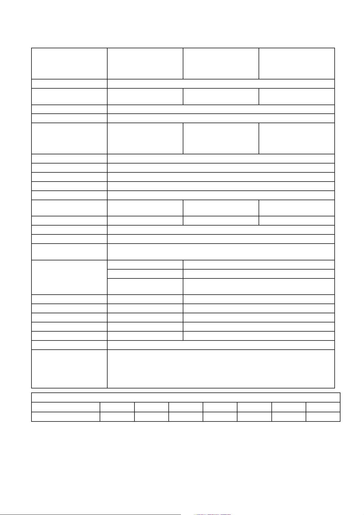
SPECIFICATIONS (Approx.)
Model PH-28RIFSN (NAT)
PH-28RIFSP (L.P.)
PH-28CIFSN (NAT)
PH-28CIFSP (L.P.)
Purpose Domestic Hot Water Supply & Circulating
Rated Gas Input
(Btu/Hr.)
Dimensions (in.) 14 7/8 (W) x 25 3/8 (H) x 11 1/8 (D)
Net Weight (lbs.) 65
Installation Indoor W all Mounting Type
Working Water Pressure 14 psi ~ 150 psi
Minimum Water Flow 0.66 GPM
Maximum Flow Rate 7.4 GPM at 45ºF Temperature Rise
Gas Connection 3/4” NPT Female (w/supplied Gas Shutoff Valve)
Water Connection 3/4” NPT Male
Vent Size 4” Special Venting
Max. Vent Length 37.5 Feet Three 90º Elbow N/A (Outdoor Installation) 37.5 Feet Three 90º Elbow
Effi ciency Rating 84%
Energy Factor 0.82
Inlet Gas Pressure
before water heater
Hot Water Supply Factory Setting 100ºF
Electrical Portion Electrical Rating 120VAC/60Hz, Less than 2 Amps
Safety Devices Oxygen Depletion Safety Sensing Burner (Indoor & Direct Vent)
Freeze Protection Minus 30ºF (Without Wind-Chill Factor)
Optional Accessory First Bath Remote Control (USC1-117); Second Bath Remote Control (USC2-117)
19,000 (Min.)
199,900 (Max.)(Modulating)
Can be vented either hori-
zontally or vertically
(Category III)
Natural Gas: Min. 4.0” w.c. Max. 10.5” w.c.
L.P. Gas: Min. 8.0” w.c. Max. 14.0” w.c. (Do not exceed maximum pressure.)
Adjusting Range R:100ºF ~ 120ºF (140ºF); C: 100°F ~ 180°F
Max. Setting Up to 140ºF(R) or 180°F(C)(w/ Main Remote Control &
Power Supply Cord 3 Pin Power Supply Cord 10 Feet (Indoor & Direct Vent)
Over Heat Limiter Film Type for Entire Heat Exchanger
Flame Failure Safety Flame Rod Type
DUOnex ™ for 2-Unit Manifolding
MIC-180 for Multi-Unit System Controller (2 to 6 units); MICS-180 for Expansion Board
(Up to 20 units); MIC Communication Cables (16, 32 & 65 feet)
High Altitude Adjustment Chips for use at altitudes above 3,280 feet, and up to 9.840 feet
PH-28ROFN (NAT)
PH-28ROFP (L.P.)
PH-28COFN (NAT)
PH-28COFP (L.P.)
19,000 (Min.)
199,900 (Max.)(Modulating)
Outdoor W all Mounting
Type
N/A (Outdoor Installation) 4” Special Venting
Dip Switch Adj.)
PH-28RDVSN (NAT)
PH-28RDVSP (L.P.)
PH-28CDVSN (NAT)
PH-28CDVSP (L.P.)
19,000 (Min.)
199,900 (Max.)(Modulating)
Direct Vent Indoor Wall
Mounting T ype
Can be vented either horizontally or vertically
(Category III)
Hot Water Flow Rate and Temperature Rise
Temp. Rise (ºF) 45 50 60 70 80 90 100
Water Flow (GPM) 7.4 6.7 5.6 4.8 4.2 3.7 3.4
Note: Special Venting: The adapter, vent pipe, elbow, vent terminal, etc. Should be UL 1738 Certifi ed Category III Stainless
Steel Venting Material (e.g. AL29-4C). “B” vent is not permitted.
Since we are constantly improving our products, all specifi cations are subject to change without notice.
- 3 -
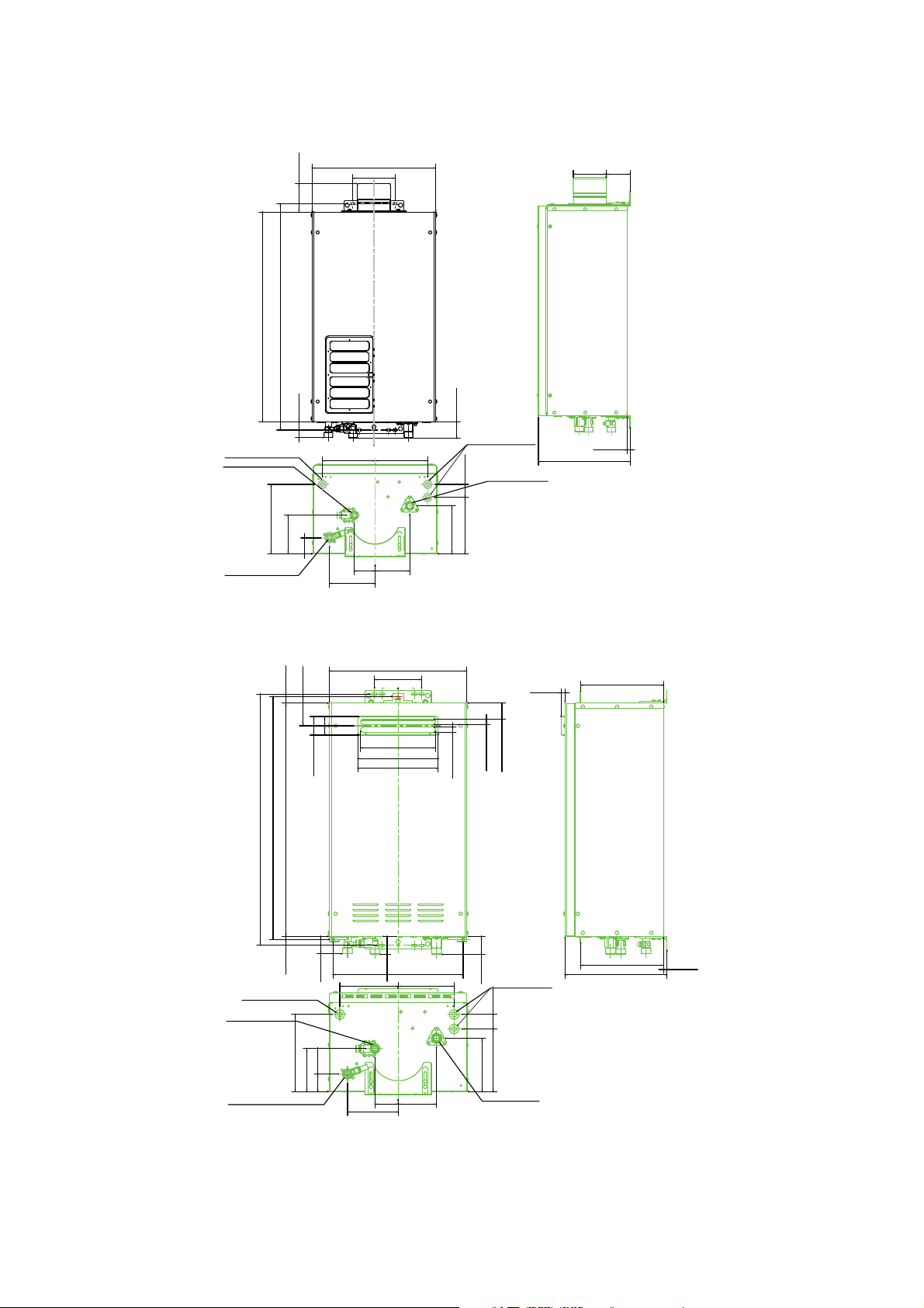
EXTERNAL DIMENSIONS
(PH-28RIFS & PH-28CIFS Indoor Model)
3.45”(87mm)
25.39” (645mm)
27.36” (695mm)
1.89” (48mm)
POWER SUPPLY CORD HOLE
COLD WATER INLET
3/4"NPT(M)
8.39” (213mm)
4.69” (119mm)
1.93” (49mm)
HOT WATER OUTLET
3/4"NPT(M)
14.96” (380mm)
5.12” (130mm)
6.34” (161mm)
2.52”
(64mm)
5.51”
(140mm)
6.34” (161mm)
4.17” (106mm)
1.97” (50mm)
WIRING HOLE
1.57”6.81” (173mm)
5.79” (147mm)
GAS INLET
(40mm)
3/4"NPT(M)
(W/Supplied Gas Shutoff Valve)
Ø4” (101.6mm)
0.39” (10mm)
11.10” (282mm)
(PH-28ROF & PH-28COF Outdoor Model)
14.96” (380mm)
5.12” (130mm)
- 4 -
0.73”
26.46” (672mm)
27.36” (695mm)
0.33”
POWER SUPPLY CORD HOLE
COLD WATER INLFT
3/4"NPT(M)
HOT WATER OUTLET
3/4"NPT(M)
(18.5mm)
3.19”
25.39” 645mm)
(8mm)
8.39” (213mm)
(81mm)
2.13” (54mm)
1.89”
(48mm)
4.69” (119mm)
1.93” (49mm)
1.97”
6.30” (160mm)
2.52”
5.51”
(64mm)
(140mm)
3.54” (90mm)
8.17”(207mm)
8.82”(224mm)
14.29” (363mm)
(50mm)
6.10” (155mm)
4.17”
(106mm)
0.59” (15mm)
0.59” (15mm)
1.97”
5.79” (147mm)
3/4"NPT(M)
(W/Supplied Gas Shutoff Valve)
1.73” (44mm)
(50mm)
WIRING HOLE
1.57”
(40mm)
6.81” 173mm)
GAS INLET
0.43”
(11mm)
9.02’ (229mm)
9.02” (229mm)
11.10” (282mm)
0.39”
(10mm)
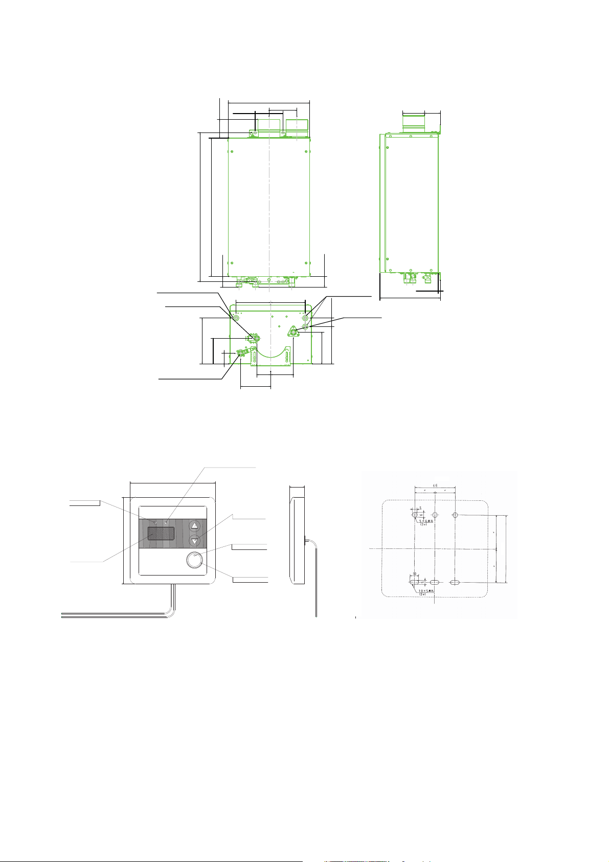
EXTERNAL DIMENSIONS
(PH-28RDVS & PH-28CDVS Direct Vent Model)
25.39” (645mm)
27.36” (695mm)
3.45
14.96” (380mm)
5.12”
(130mm)
5.12” (130mm)
Ø4” (101.6mm)
POWER SUPPLY CORD HOLE
COLD WATER INLFT
3/4"NPT(M)
HOT WATER OUTLET
(Remote Control)
4 3/4” (120mm)
COMBUSTION
INDICATOR
PRIORITY
F
4 3/4” (120mm)
LED DISPLAY
°
8.39” (213mm)
3/4"NPT(M)
POWER
ON/OFF
1.89” (48mm)
6.34” (161mm)
4.69” (119mm)
1.93” (49mm)
PRIORITY INDICATOR
TEMPERATURE
ADJUSTMENT
BUTTON
POWER ON/OFF
INDICATOR
POWER ON/OFF
BUTTON
2.52”
(64mm)
5.51”
(140mm)
6.34” (161mm)
4.17”
(106mm)
7/8” (21mm)
1.97” (50mm)
WIRING HOLE
1.576.81” (173mm)
GAS INLWR
3/4"NPT(M)
(W/Supplied Gas Shutoff Valve)
5.79” (147mm)
0.39” (10mm)
11.10” (282mm)
1 7/8” 46mm)
3 1/4” (83.5mm)
- 5 -

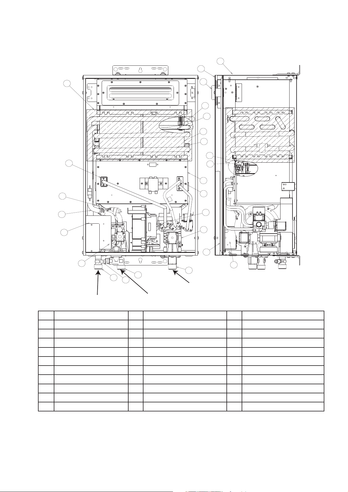
SCHEMATIC CONSTRUCTION
(PH-28RIFS & PH-28CIFS Indoor Model)
4
2
1
26
6
8
5
7
10
14
12
13
11
19
17
18
24
22
Hot Water Outlet
Connection 3/4” NPT (M)
21
23
Water Inlet Connection
3/4” NPT (M)
20
9
15
3
16
25
Gas Connection 3/4” NPT (F)
(W/Supplied Gas Shutoff Valve)
No. Name of Parts No. Name of Parts No. Name of Parts
1 Front Cover 11 Sensing Burner Assembly 21 Water Inlet Connection
2 Back Cover 12 Orifi ce Stand L Assembly 22 Hot Water Outlet Connection
3 Air Filter Assembly 13 Orifi ce Stand R Assembly 23 Drain Valve
4 Exhaust Flue Top 14 Electrode 24 Water Control Body Assy.
5 Heat Exchanger 15 Fan Assembly 25 PC Board
6 Heat Transfer Coil 16 Gas Control V alve Assembly 26 Film Type OHL
7 Water Supply Coil 17 Water Supply Pipe
8 Turbulence Plate 18 Hot Water Supply Pipe
9 Inner Case 19 Bypass Pipe
10 Main Burner 20 Gas Connection
- 6 -
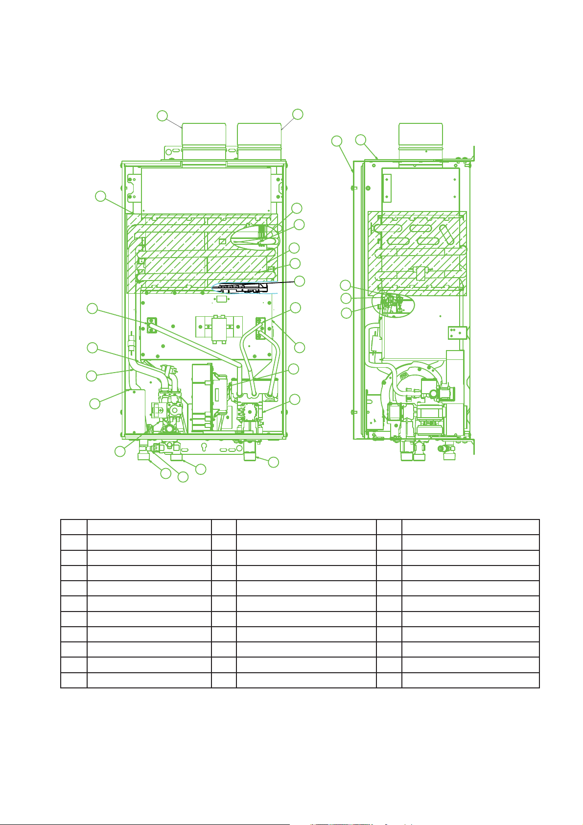
SCHEMATIC CONSTRUCTION
(PH-28ROF & PH-28COF Outdoor Model)
2
1
25
4
6
8
5
7
10
11
13
9
18
16
17
12
14
15
3
23
21
20
22
19
Gas Connection 3/4” NPT (F)
24
(W/Supplied Gas Shutoff Valve)
Hot Water Outlet
Connection 3/4” NPT (M)
Water Inlet Connection
3/4” NPT (M)
No. Name of Parts No. Name of Parts No. Name of Parts
1 Front Cover 11 Orifi ce Stand L Assembly 21 Hot Water Outlet Connection
2 Back Cover 12 Orifi ce Stand R Assembly 22 Drain Valve
3 Rain Cover 13 Electrode 23 Water Control Body Assy.
4 Flue Outlet 14 Fan Assembly 24 PC Board
5 Heat Exchanger 15 Gas Control Valve Assembly 25 Film Type OHL
6 Heat Transfer Coil 16 Water Supply Pipe
7 Water Supply Coil 17 Hot Water Supply Pipe
8 Turbulence Plate 18 Bypass Pipe
9 Inner Case 19 Gas Connection
10 Main Burner 20 Water Inlet Connection
- 7 -
SCHEMATIC CONSTRUCTION
(PH-28RDVS & PH-28CDVS Direct Vent Model)
11
18
16
24
14
12
3
2
1
6
8
5
7
26
9
10
13
25
4
17
23
21
22
20
15
19
No. Name of Parts No. Name of Parts No. Name of Parts
1 Front Cover 11 Orifi ce Stand L Assembly 21 Hot Water Outlet Connection
2 Back Cover 12 Orifi ce Stand R Assembly 22 Drain Valve
3 Air Intake 13 Flame Rod 23 Water Control Body Assy.
4 Exhaust Flue Top 14 Fan Assembly 24 Film Type OHL
5 Heat Exchanger 15 Gas Control Valve Assembly 25 Sensing Burner Assembly
6 Heat Transfer Coil 16 Water Supply Pipe 26 Burner Rod
7 Water Supply Coil 17 Hot Water Supply Pipe
8 Turbulence Plate 18 Bypass Pipe
9 Inner Case 19 Gas Connection
10 Main Burner 20 Water Inlet Connection
- 8 -
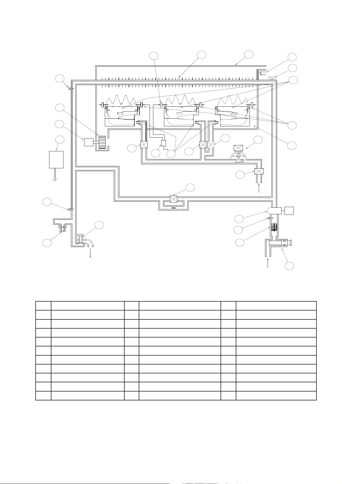
OPERATIONAL PRINCIPLE
9
Gas
21
13
20
23
15
18
22
17
5
24
25
27
M
12
16
14
19
11
10
2
Inlet
6
M
7
1
4
26
Hot Water
Outlet
3
8
Water
Inlet
No. Name of Parts No. Name of Parts No. Name of Parts
1 Hot Water T ap 11 Solenoid Valve 2 21 Exhaust Outlet
2 Bypass Solenoid Valve 12 Solenoid Valve 3 22 Combustion Chamber
3 Water Flow Sensor 13
Proportional Gas Control Valve
23 Freeze Protection Heater
4 Water Inlet Thermistor 14 Orifi ce 24 Fan
Heat Exchanger Thermistor
5
Hot W ater Outlet Thermistor
6
15 Main Burner 25 Fan Motor
16 Igniter 26 Drain V alve
7 Water Flow Servo 17 Electrode 27 PC Board
8 Water Filter 18 Flame Rod
9 Gas Inlet Solenoid Valve 19 Heat Exchanger
10 Solenoid Valve 1 20 Film Type OHL
- 9 -

OPERATIONAL PRINCIPLE
WHEN SUPPLYING HOT WATER
1) By opening the Hot Water Top (1), the water fl ows through the Water Flow Sensor (3) to the Heat
Heat Exchanger (19).
2) The frequency signal is given from the Water Flow Sensor (3) and when the PC Board (27) senses the signal
that reached a certain frequency, the Fan (24) starts to turn round.
3) After the Fan (24) turned round and pre-purged, the Gas Inlet Solenoid Valve (9), Solenoid Valve 1 (10) and
Solenoid Valve 2 (11) open at the same time. Then, the Proportional Gas Control Valve (13) becomes an
ignition motion and allows the gas to fl ow to the Main Burner (15) (and Sensing Burner for PH-28RIFS,
PH-28CIFS, PH-28RDVS and PH-28CDVS only).
4) At the same time, the Igniter (16) continuously makes sparks and ignites the Main Burner (15).
After ignited, when the Flame Rod (18) senses the fl ame and make sure the combustion, the Proportional
Gas Control Valve (13) fi nishes the ignition motion.
5) After fi nished the ignition motion, the proportional gas control is started. When there is a temperature
difference between the hot water temperature that is sensed by the Hot Water Outlet Thermistor (6) and the
set temperaturer on the Remote Control, the PC Board (27) judges it and open or close the Solenoid
Valve 1 (10), Solenoid Valve 2 (11) and Solenoid Valve 3 (12), and also the Proportional Gas Control Valve
(13) continuously adjusts the gas volume in order to maintain the outlet temperature from the Heat
Exchanger (19).
The Water Flow Servo (7) also adjusts the proper amount of water fl ow to supply a stable hot water
temperature at all times.
6) According to the adjustment of the gas volume by the Proportional Gas Control Valve (13), a signal from the
PC Board (27) is also sent to the Fan Motor (25) in order to maintain the relation between the gas volume
and air volume at all times.
7) (For PH-28RIFS, PH-28CIFS, PH-28RDVS and PH-28CDVS only) When the air intake or venting is
blocked, or the oxygen of the air intake is not suffi cient, the output of the Thermocouple that is located at the
Sensing Burner would be changed. The PC Board (27) senses this change and controls the Fan (24),
Proportional Gas Control Valve (13), etc. in order to prevent the imperfect combustion. Further, if such
condition is proceeded, it shuts off the Gas Inlet Solenoid Valve (9), Solenoid Valve 1 (10),
Solenoid Valve 2 (11), Solenoid Valve 3 (12) and Proportional Gas Control Valve (13) in order to stop the
operation.
8) When the Hot Water Tap (1) is closed, the frequency signal from the Water Flow Sensor (3) is stopped and
the Gas Inlet Solenoid Valve (9), Solenoid Valve 1 (10), Solenois Valve 2 (11), Solenoid Valve 3 (12) and
Proportional Gas Control Valve (13) turn off and becomes a post-purge motion.
9) When the time of the post-purge is up, the Fan (24) stops.
- 10 -
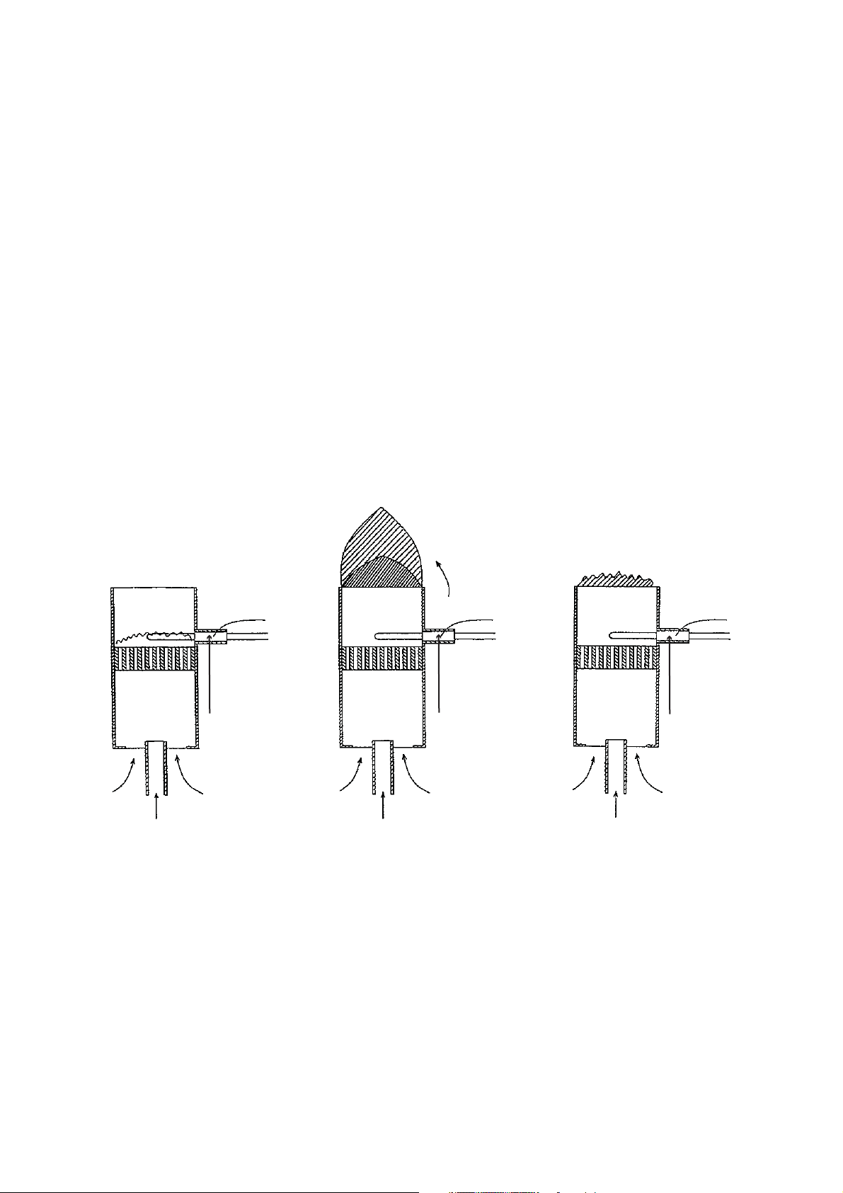
Oxygen Depletion Safety Device (O.D.S.D.)
[Sensing Burner]
(Indoor Model & Direct Model Only)
The sensing burner is a all primary air type ceramic burner that consists of an outer jacket surrounding the flame
opening and a thermocouple to detect flame temperature. In case oxygen level decreases due to blocked or
clogged air intake or flue venting, or by contaminated air, location of the flame will change as well as its
temperature by the thermocouple. The sensing burner is located in the part of the main burner and designed to
monitor the flame condition at all times. Therefore, it shut off gas before the imperfect combustion occurs in the
main burner.
NORMAL
========
BLOCKING LACK OF OXYGEN
========================
The flame lifts away
from the thermocouple.
(Blocked or clogged vent, fan etc.)
Secondary Air
The flame lifts away
from the thermocouple.
(Contaminated air in room, etc.)
ThermocoupleThermocouple Thermocouple
Gas
Primary Air Primary Air
(Decrease)
Gas
Primary Air
(Lack of Oxygen)
Gas
- 11 -
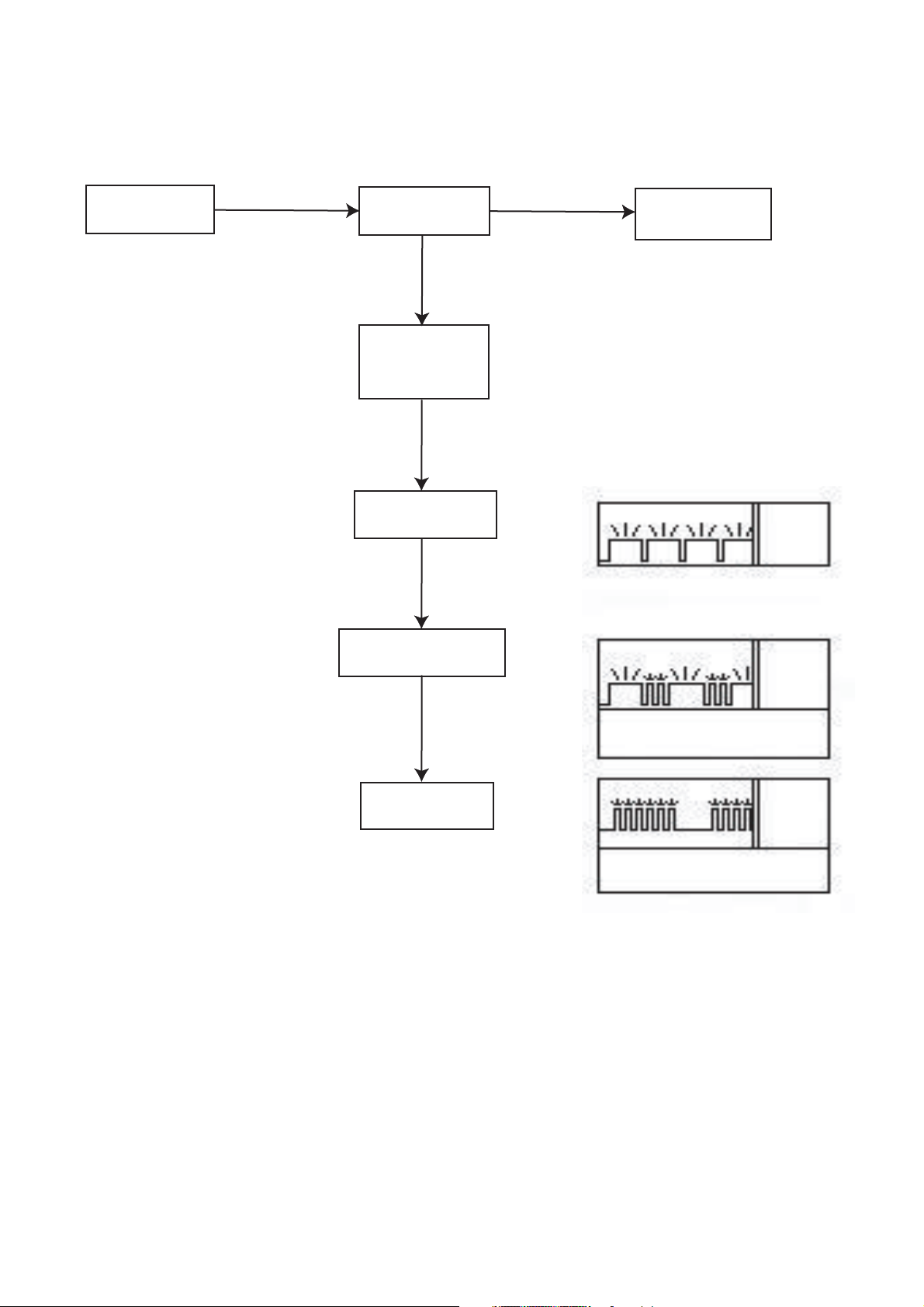
If Imperfect Combustion Happens.....
(Indoor Model &
Direct Model Only)
Ignition
Sensor Stand-By
Lead Time
Cold: 2 Min.
Hot: 30 Sec. - 1 Min.
Decrease of Thermo
Electric Current
Decrease of Thermo
Electric Current
Secondary Warning
(Alarm + Light)
Normal Air
Flow Rate
Decrease of Thermo
Electric Current
Input Down
(Increase Air
Flow Rate)
Primary Warning
(Light)
Water Flow
Servo OFF
Automatic Control To Resolve
Imperfect Combustion
(Display on Remote Control)
Both Red and Green
flashing at the same time
Both Red and Green
flashing at the same time
Extinction
Post- Purging
Monitor Code
No Error
Code
Monitor Code
05
Decrease of Thermo
Electric Current
Shut Down
(After- Purging)
NOTE: Shutdown by impeefect combustion can be reset by pressing power switch (ON/OFF Button).
However, if it occurs 5 times within 4 hours, the water heater will not recover for the next 4 hours.
Every 60 seconds, you hear
noticing alarm (Beep sound).
Only Red lamp flashing
6 times
Monitor Code
13
- 12 -
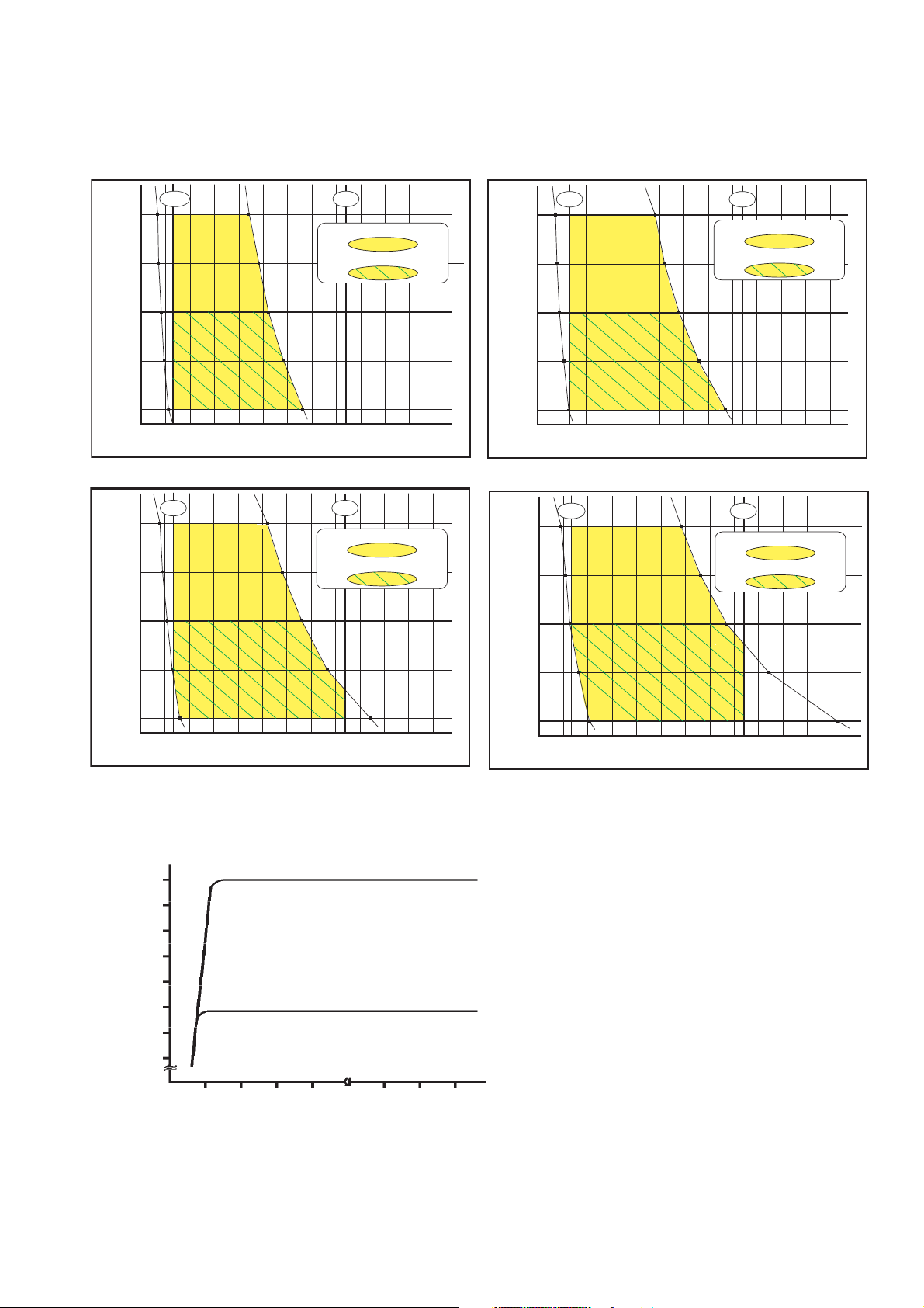
Capacity
Hot Water Capacity Curve: Residential Models
Inlet Water Temperature : 40°F
0.66
GPM
140
130
120
Outlet Temperature (°F)
110
100
0.5 1.0 2.0 3.0 4.0 5.0 6.0 7.0 8.0 9.0 10.0 11.0
Inlet Water Temperature : 60°F
0.66
GPM
140
130
When maximum temperature is set at 140°F
When maximum temperature is set at 120°F
Water Flow Rate (GPM)
When maximum temperature is set at 140°F
When maximum temperature is set at 120°F
GPM
GPM
Inlet Water Temperature : 50°F
7.4
Outlet Temperature (°F)
0.66
GPM
140
130
120
110
100
0.5 1.0 2.0 3.0 4.0 5.0 6.0 7.0 8.0 9.0 10.0 11.0
Water Flow Rate (GPM)
7.4
GPM
When maximum temperature is set at 140°F
When maximum temperature is set at 120°F
Inlet Water Temperature : 70°F
7.4
0.66
GPM
140
130
7.4
GPM
When maximum temperature is set at 140°F
When maximum temperature is set at 120°F
120
Outlet Temperature (°F)
110
100
0.5 1.0 2.0 3.0 4.0 5.0 6.0 7.0 8.0 9.0 10.0 11.0
Water Flow Rate (GPM)
Water Pressure & Water Flow Rate:
7.4
6.9
6.4
5.8
5.3
4.8
Water Flow Rate (GPM)
4.3
Inlet Water Temperature: 70
(At The Outlet Hot Water Temperature : 110 )
Inlet Water Temperature: 40
°F
°F
(7.4)
(4.8)
120
Outlet Temperature (°F)
110
100
0.5 1.0 2.0 3.0 4.0 5.0 6.0 7.0 8.0 9.0 10.0 11. 0
Water Flow Rate (GPM)
°F
14 30 45 60 105 120
135
Water Pressure (psi)
- 13 -
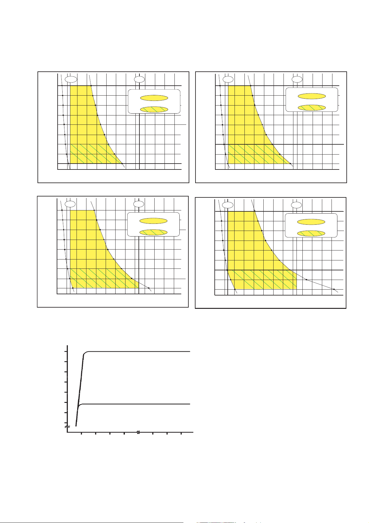
Capacity
Hot Water Capacity Curve: Commercial Models
Inlet Water Temperature : 40°F
0.66
GPM
180
170
160
150
140
130
Outlet Temperature (°F)
120
110
100
0.5 1.0 2.0 3.0 4.0 5.0 6.0 7.0 8.0 9.0 10.0 11.0
Inlet Water Temperature : 60°F
0.66
GPM
180
170
160
150
140
130
Outlet Temperature (°F)
120
110
100
0.5 1.0 2.0 3.0 4.0 5.0 6.0 7.0 8.0 9.0 10.0 11.0
When maximum temperature is set at 180°F
When maximum temperature is set at 120°F
Water Flow Rate (GPM)
When maximum temperature is set at 180°F
When maximum temperature is set at 120°F
Water Flow Rate (GPM)
GPM
GPM
Inlet Water Temperature : 50°F
7.4
Outlet Temperature (°F)
0.66
GPM
180
170
160
150
140
130
120
110
100
0.5 1.0 2.0 3.0 4.0 5.0 6.0 7.0 8.0 9.0 10.0 11.0
Water Flow Rate (GPM)
7.4
GPM
When maximum temperature is set at 180°F
When maximum temperature is set at 120°F
Inlet Water Temperature : 70°F
7.4
Outlet Temperature (°F)
0.66
GPM
180
170
160
150
140
130
120
110
100
0.5 1.0 2.0 3.0 4.0 5.0 6.0 7.0 8.0 9.0 10.0 11. 0
Water Flow Rate (GPM)
7.4
GPM
When maximum temperature is set at 180°F
When maximum temperature is set at 120°F
Water Pressure & Water Flow Rate:
7.4
6.9
6.4
5.8
5.3
4.8
Water Flow Rate (GPM)
4.3
- 14 -
Inlet Water Temperature: 70
(At The Outlet Hot Water Temperature : 110 )
Inlet Water Temperature: 40
14 30 45 60 105 120
°F
°F
(7.4)
(4.8)
135
°F
Water Pressure (psi)
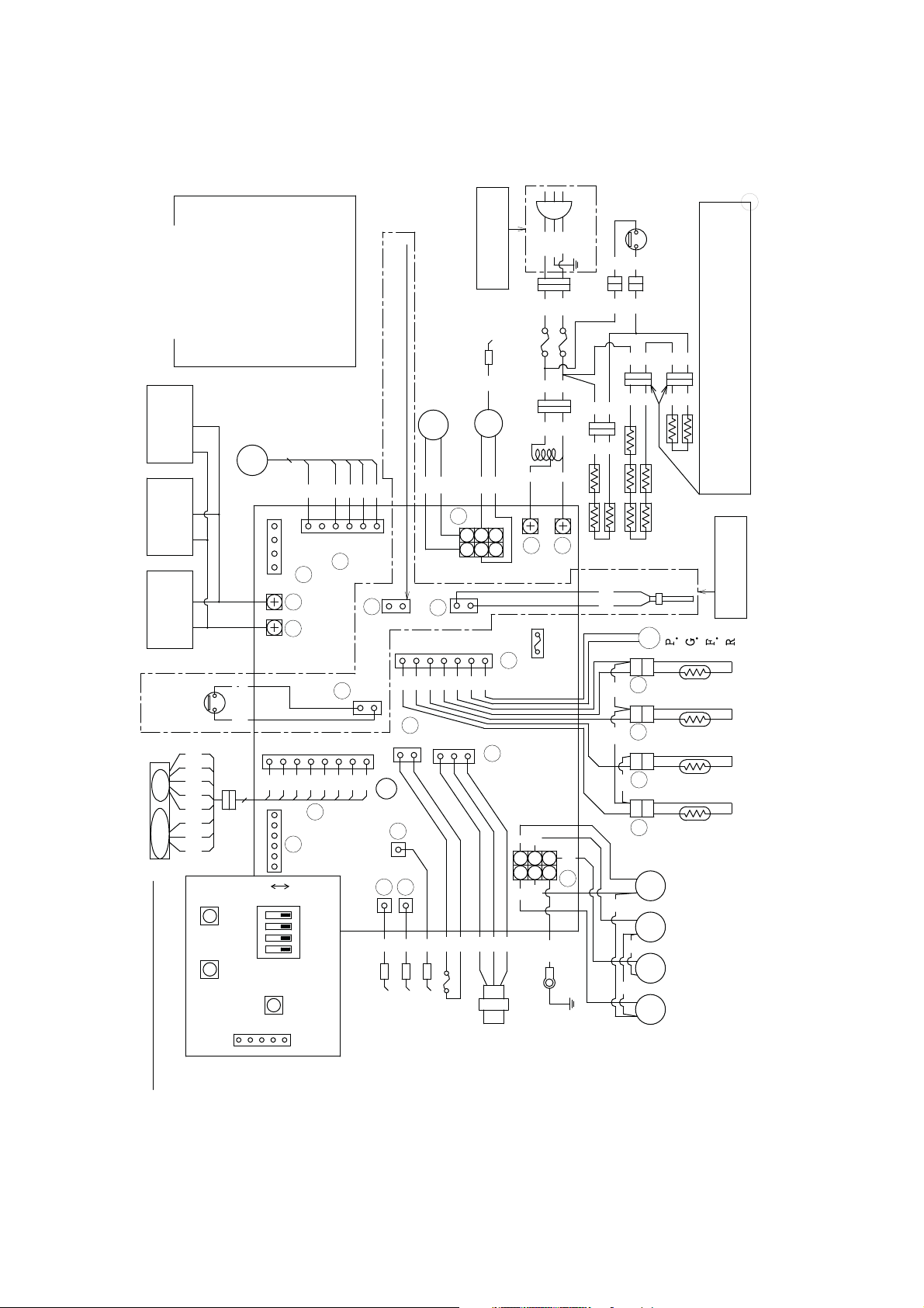
Wiring Diagram
A wiring diagram is also located on the inside of the front cover panel.
Slightly different by model and serial number.
AC
120V
W
BK
G/Y
GND
BK
BK
(RED)
W W
BK
(BLUE)
W
H
M
T
E
R
W
R
BK BK
BK
COLOUR CODE
W:WHITE
R:RED
CONTROL2
REMOTE
BATH
(USC2-117)
CONTROL1
REMOTE
BATH
(USC1-117)
REMOTE
MAIN
CONTROL
(UMC-117)
AIR
INTAKE
FILTER
SWITCH
BR
W
MOTOR
R GR Y B O
B
LIMITER
WATER VOLUME
CONTROL MOTOR
SW2
SW1
B:BLUE
BR:BROWN
BK:BLACK
GY:GRAY
GR:GREEN
FAN
MOTOR
5
FM
1
2
3
4
D E
W
W
8
6
7
R
GR
BK
8
A
ON
OFF
MAX
BUTTON
MIN
BUTTON
SW3
ADJUSTER
Y:YELLOW
O:ORANGE
G/Y:GREEN/YELLOW
W B R O Y
1
2
3
4
5
6
G
F
P
O
2
1
1
2
3
4
5
Y B O
W
BR
B
4
3
2
1
DIP SWITCH
BUTTON
LED
FOR INDOOR
MODEL ONLY
W
BK
BK
IG
FUSE(3A)
W
BK
W
BK
ELECTRODE
WATER BY-PASS
SOLENOID VALVE
WV
IGNITER
CONNECTOR FOR CHECKING
THERMOELECTROMOTIVE FORCE
GR
GR
GY
R
AC
100V
R
GY
TRANSFORMER
H
5
6
4
I
3
2
1
J
Q
1
4
5
6
W Y R
2
2
3
BK
BK
1
R
R
FUSE
(5A)
2
1
7
B
U
2
T
L
M
W W R
1
B
1 3 2
W
S
1
4
B Y
R
BK
BR
BOARD
CIRCUIT
W
R
2
5
6 3
K
BK
G/Y
GND
BK
FROST
PROTECTION
THERMOSTAT
BK
W
W W
W
BK
(RED)
W
W
W
THE CONNECTORS OF DUAL AND MULTIPLE
ANTI-FROST
HEATER
C O U
O
+
-
R1
R2
R3 R4
BK
BK
BK
L
P
E
V E
L
V A
PSV
E R
I S
T
H
M
O T W
H
L E
T
U
O
H E R M
T
X C H A N
E
E A
T
H
E R
I S
T
H
M
L E T
I
N
E R
T
A
W
E R M
T
H
I
A
R
M B
E N
I
A
L V E
V A
O L
N O
S
E
A S
SV0
G
V A
O L E N O I D
SV1
S
L V E 2
V A
O L E N O I D
S
L V E 3
V A
O L E N O I D
SV3 SV2
S
ARE INTERAPPLICABLE TO THE BODY
CONNECTORS EACH OTHER.(RED)
FOR INDOOR
MODEL ONLY
O R
T
E R
T
A
T
S T
R
I
O
R
E
G
T
R
O
S
R
I
T
O
T
0
I
D
I
L
T
E
N
L
1
V E
WIRING DIAGRAM
WATER
OVER HEAT
FLAME ROD1
FLAME ROD2
LIMITER
FLAME ROD3
FLOW
SENSOR
- 15 -
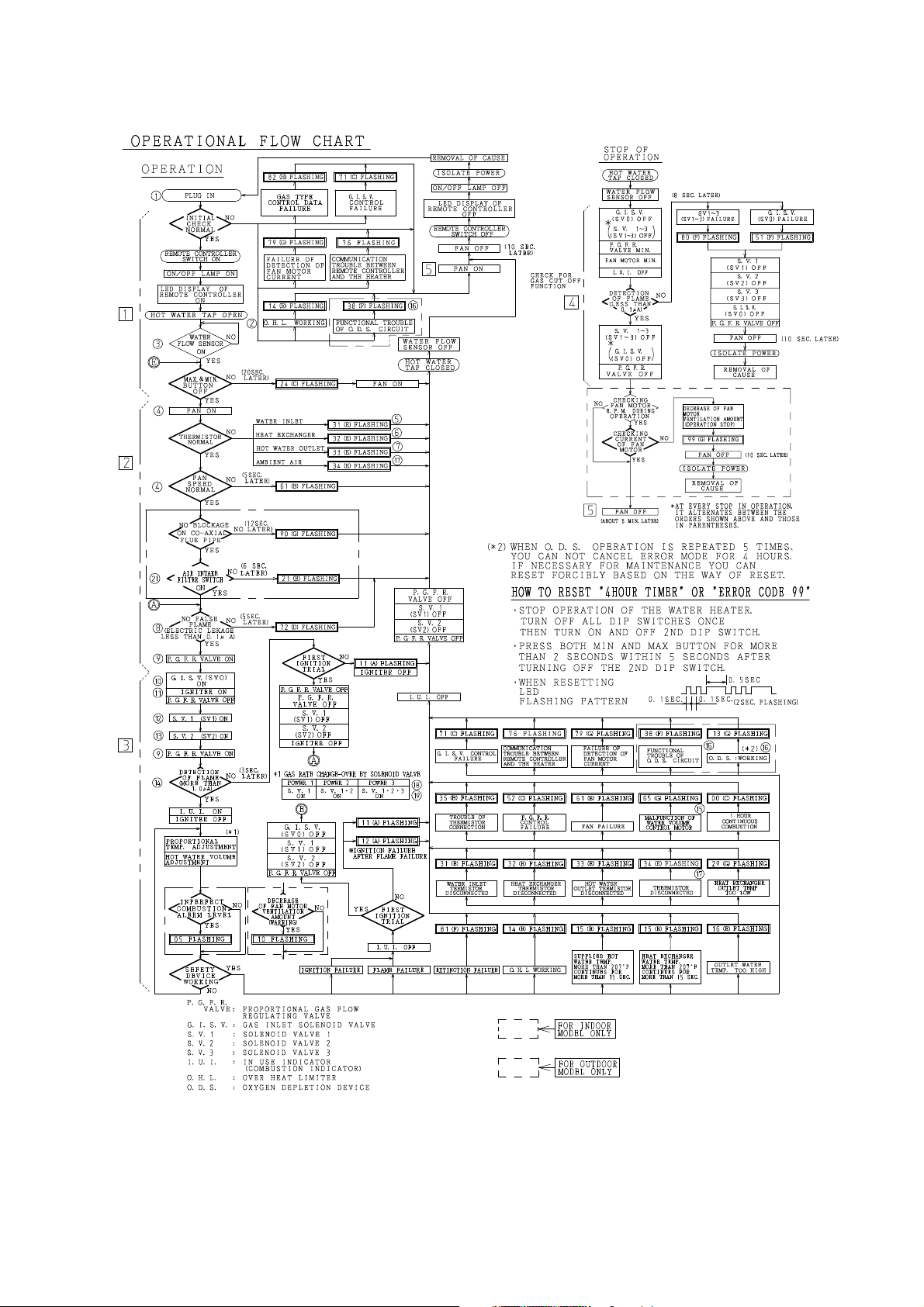
Operational Flow Chart & Maintenance Information
- 16 -
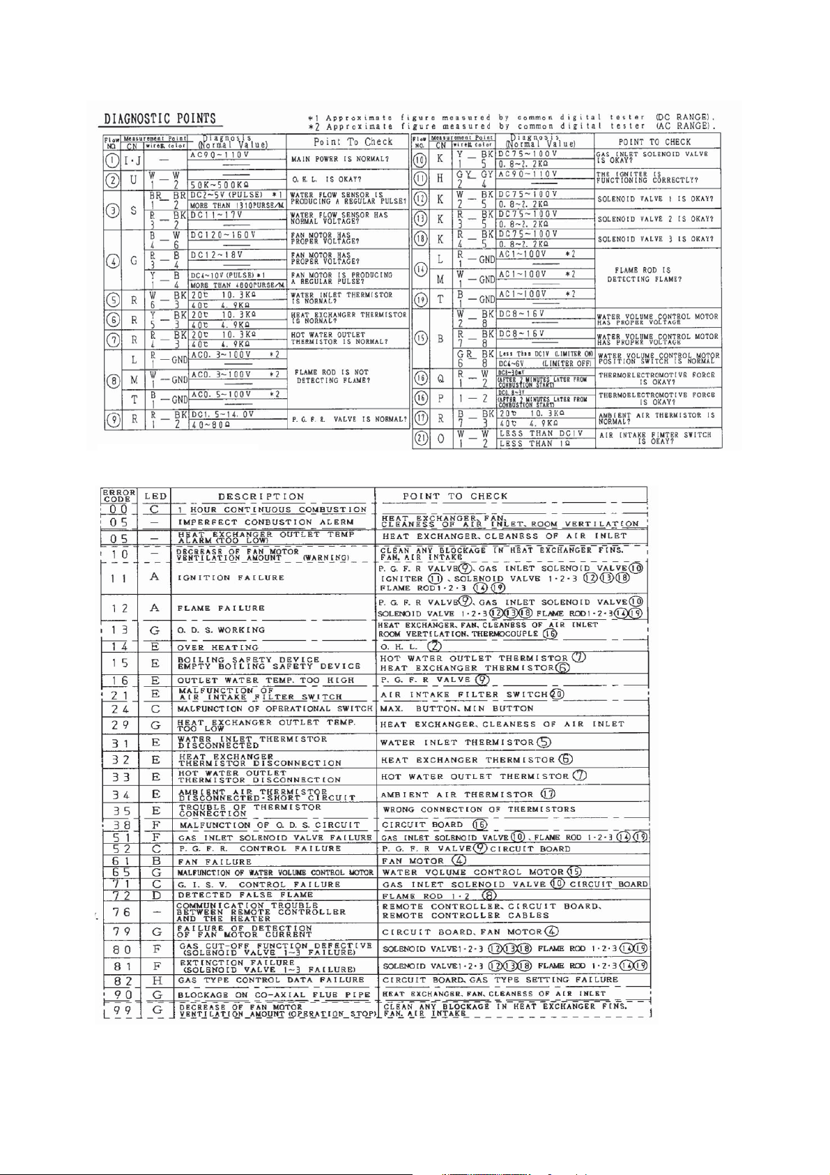
Diagnostic Points
k
The voltage showed is the value of operating condition when the water heater operates according to the flow chart.
The resistance showed is the value of load side when turned off the electric power and disconnected the connector.
5
- 17 -
- 18 -
MAINTENANCE INFORMATION SHOWN IN LED DISPLAY OF REMOTE CONTROL
ABOVE
- 19 -

Error Codes
Code Fault Remedy
05 Imperfect Combustion Alarm Clean air inlet fi lter.
Clean combustion air fan.
Clean heat exchanger fi ns.
Check for adequate combustion air ventilation openings and clean if necessary.
Check vent system for partial blockage and correct as necessary.
10 Decrease of Fan Motor Ventilation
Amount
Air Supply or Exhaust Blockage
(Warning)
11 Ignition Failure
No Ignition
12 Flame Failure Ensure you have gas to the appliance.
13 Oxygen Depletion Sensor (O.D.S.)
Working (Poor or Improper Combustion)
14 Over Heating Ensure high fi re and low fi re manifold pressure is correct.
Check all vent components for proper connections.
Check that nothing is blocking the fl ue inlet or exhaust.
Ensure condensation trap/drain was installed correctly.
Ensure heat exchanger fi ns, fan, and air intake are not blocked.
Ensure you have gas to the appliance and valves are turned ON.
Ensure gas type and pressure is correct.
Bleed all air from gas lines.
Ensure gas line, meter, and regulator are sized properly.
Ensure appliance is properly grounded.
Check gas solenoid valves for open or short circuits.
Ensure igniter is operational.
Check igniter wiring harness for damage.
Ensure maximum vertical vent length does not exceed allowable limits.
Ensure total maximum vent length does not exceed allowable limits.
Ensure gas type and pressure is correct.
Bleed all air from gas lines.
Ensure fl ame rod wire is connected.
Check fl ame rod for carbon build-up.
Ensure gas line, meter, and regulator are sized properly.
Ensure appliance is properly grounded.
Check gas solenoid valves for open or short circuits.
Check power supply for proper voltage and voltage drops.
Disconnect remote control; if it runs.
Disconnect and re-connect all wiring harnesses on unit and PC board.
Ensure proper venting material was installed.
Ensure maximum vertical vent length does not exceed allowable limits.
Ensure total maximum vent length does not exceed allowable limits.
Ensure there is plenty of fresh air to the unit.
Unit needs 1 square inch (6.5 cm2) for each 1,000 BTU of input.
Check for a foreign materials in combustion chamber and/or O.D.S. Device.
Check gas type of unit and ensure it matches gas type being used.
Check heat exchanger for cracks and/or separations.
Check for restrictions in airfl ow around unit and vent terminal.
Check for a foreign materials in combustion chamber and/or exhaust piping.
Check for clogged heat exchanger (scale buildup).
- 20 -
Code Fault Remedy
15 Boiling Safety Device Check for closed water heater inlet valve or restriction in cold water inlet
pipe (must be fully open).
Check for clogged heat exchanger (scale buildup).
On commercial water heater, lower set point temperature below 180F at
high altitude.
16 Outlet Water Temperature Too High
Over T emperature Warning
21 Malfunction of Air Intake
Filter Switch
24 Malfunction of Operational Switch Disconnect remote control and retry.
29 Heat Exchanger Outlet Temp.
Too Low
31 Water Inlet Thermistor Fault Check thermistor wiring for damage.
32 Heat Exchanger Thermistor Fault Check thermistor wiring for damage.
33 Hot Water Outlet Thermistor Fault Check thermistor wiring for damage.
34 Ambient Air Thermistor Fault Check thermistor wiring for damage; Ohm out thermistor.
35 Improper Thermistor Connection Check that all thermistors are connected to proper connections on PCB.
38 Malfunction of O.D.S. Circuit The sensor itself is not responding to a self check from the PCB. Check
51 Gas Inlet Solenoid Valve Fault Check gas inlet solenoid valve wiring harness for loose or damage termi-
52 Proportional Gas Control Valve
Fault
61 Fan Failure Ensure fan motor will turn freely. (Motor will operate with a small amount
Check for clogged heat exchanger (scale buildup).
Check for restrictions in airfl ow around unit and vent terminal.
Check for a foreign materials in combustion chamber and/or exhaust piping.
Make sure air fi lter door is properly seated.
Make sure front panel is properly installed.
Verify unit is electrically grounded.
Press max button on PCB to reset; Press min button on PCB to reset.
Clean air inlet screen.
Clean heat exchanger fi ns.
Ohm out thermistor.
Check and clean scale from thermistor.
Ohm out thermistor.
Check and clean scale from thermistor.
Ohm out thermistor.
Check and clean scale from thermistor.
Check and clean ambient air thermistor.
Ensure fan blade is tight on motor shaft and it is in good condition.
Check for restrictions in airfl ow around unit and vent terminal.
wiring harness. Check for proper voltage.
nals.
Ohm out solenoid valve.
Check proportional gas control valve wiring harness for loose or damage
terminals.
Ohm out proportional gas control valve.
of restriction.)
Check wiring harness to motor for damaged and/or loose connections.
Check venting length not to exceed max lengths and bends.
- 21 -
 Loading...