

Paloma PH-25R OFN, PH-25R OFP User Manual
!
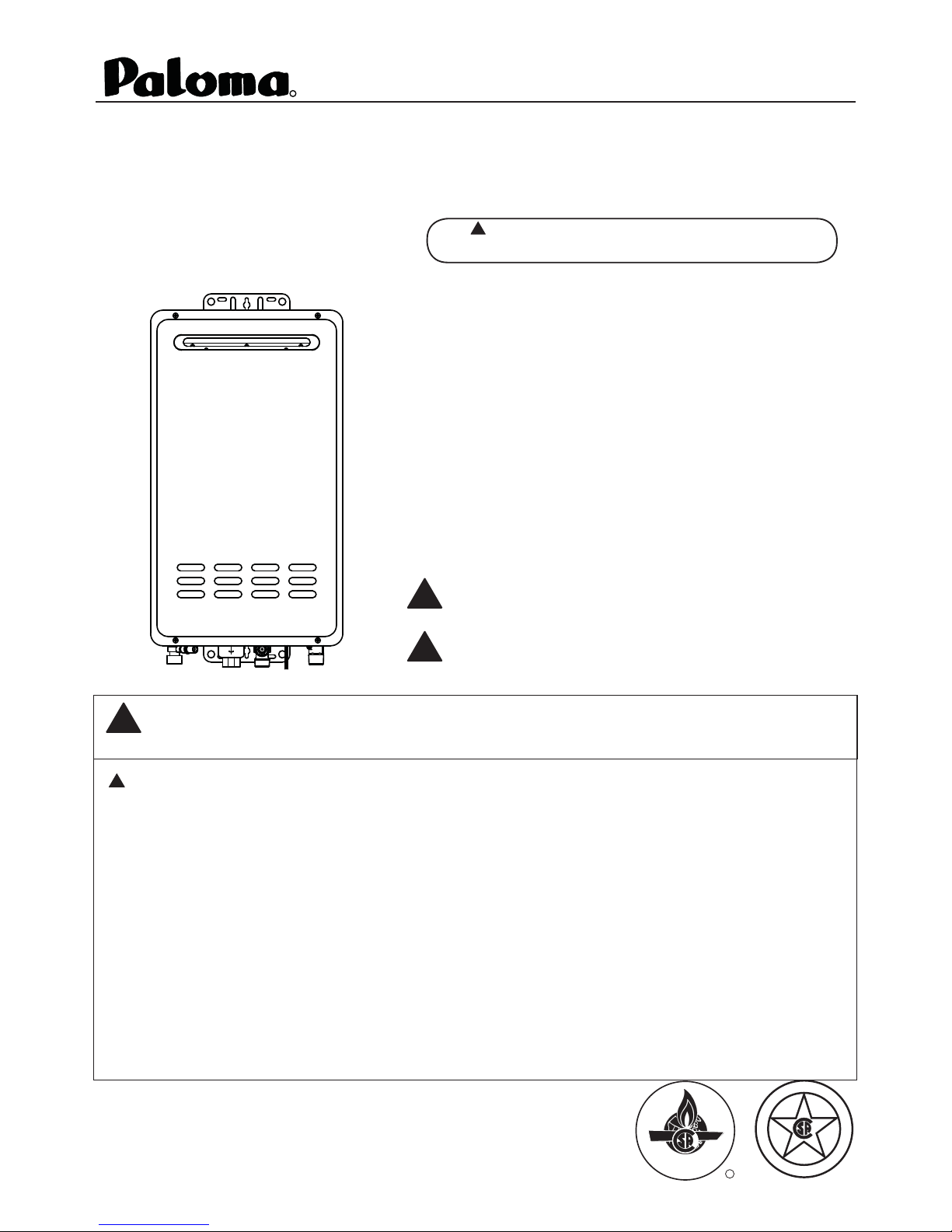
Use & Care Manual
R
Outdoor Gas
With Installation Instructions for the Installer
Tankless Water Heater
!
Warning: This water heater is not suitable
for use in manufactured (mobile) homes!
The purpose of this manual is twofold: one, to provide the installer with
the basic directions and recommendations for the proper installation
and adjustment of the water heater; and two, to the owner–operator,
to explain the features, operation, safety precautions, maintenance and
troubleshooting of the water heater. This manual also includes a parts
list.
It is very important that all persons who are expected to install, operate
or adjust this water heater read the instructions carefully so they may
understand how to perform these operations. If you don’t understand
these instructions or any terms within it, seek professional assistance.
Any questions regarding the operation, maintenance, service or warranty
of this water heater should be directed to the seller from whom it was
purchased. If additional information is required, refer to the section on
If You Need Service.
Do not destroy this manual. Please read carefully and keep in a safe
place for future reference.
Recognize this symbol as an indication of Important Safety
Information!
California Proposition 65 Warning: This product contains
!
chemicals known to the State of California to cause cancer, birth
defects or other reproductive harm.
WARNING: If the information in these instructions is not followed exactly,
!
a fire or explosion may result, causing property damage, personal injury or death.
!
FOR YOUR SAFETY!
— Do not store or use gasoline or other
flammable vapors or liquids or other
combustible materials in the vicinity of this
or any other appliance. To do so may result
in an explosion or fire.
If you cannot reach your gas supplier, call
the fire department.
Do not return to your home until authorized
by the gas supplier or fire department.
— Improper installation, adjustment,
— WHAT TO DO IF YOU SMELL GAS
Do not try to light any appliance.
Do not touch any electrical switch; do not
use any phone in your building.
alteration, service or maintenance can cause
property damage, personal injury or death.
Refer to this manual. Installation and service
must be performed by a qualified installer,
service agency or the gas supplier.
Immediately call your gas supplier
from a neighbor’s phone. Follow the
gas supplier’s instructions.
Models:
PH-25R OFN (Natural Gas)
PH-25R OFP (L.P. Gas)
CERTIFIED
R
I
S
G
E
N
D
C
E
D
R
E
I
T
F
I
®
Safety Information
Safety Precautions . . . . . . . 3–6
LP Gas Models . . . . . . . . . . . 5
FOR YOUR RECORDS
Write the model and serial numbers here:
#
Installation Instructions
Location, Outdoor . . . . . . .7-10
W ater Connections . . . . 11-13
Gas Supply . . . . . . . . . . . . . . 14
High Altitude . . . . . . . . . . . . .14
Remote Control . . . . . . . . 15,16
Electrical Connection . . . . . .17
Typical Installation . . . . . . . .18
Pipe Insulation . . . . . . . . . . . .19
Installation Checklist . . . . . . .20
Operating Instructions
Lighting Instructions . . . . . . 21
W ater Temperature . . . . 22, 23
Care and Cleaning
Maintenance . . . . . . . . . . . . . 24
Housekeeping . . . . . . . . 24, 25
Burner Inspection . . . . . . . . 25
Extended Shut-Down . . . . . .25
Draining . . . . . . . . . . . . . . . . 26
Freeze Protection . . . . . . . . . .26
#
You can find them on a label on the appliance.
Staple sales slip or cancelled check here.
Proof of the original purchase date is needed to obtain service
under the warranty.
READ THIS MANUAL
Inside you will find many helpful hints on how to use and
maintain your water heater properly. A little preventive care
on your part can save you time and money over the life of your
water heater.
You’ll find many answers to common problems in
the Troubleshooting Guide. If you review the chart of
Troubleshooting Tips first, you may not need to call for service.
READ THE SAFETY INFORMATION
Your safety and the safety of others are very important. There
are many important safety messages in this manual and on your
appliance. Always read and obey all safety messages.
This is the safety alert symbol. Recognize this symbol
as an indication of Important Safety Information!
!
This symbol alerts you to potential hazards that can
kill or hurt you and others.
T r oubleshooting T ips
Before Y ou Call
For Service . . . . . . . . . . . 27, 28
Customer Service
Parts List . . . . . . . . . . . . . . . . 29
If You Need Service . . . . . . .32
Qualified Installers Only!
Maximum Temperature
Adjustment. . . . . . . . . . . . .30
Minumum Temperature
Adjustment . . . . . . . . . . . . . 31
High Altitude
Adjustment. . . . . . . . . . . . . . 31
2
All safety messages will follow the safety alert symbol and
either the word “DANGER”, “WARNING”, “CAUTION”
or “NOTICE”.
These words mean:
DANGER
!
!
WARNING
!
CAUTION
may result in minor or moderate
injury.
Notice:
specified procedure or maintain
a specific condition.
An imminently hazardous situation
that will result in death or serious
injury.
A potentially hazardous situation that
could result in death or serious injury
and/or d amage to property.
A potentially hazardous situation that
Attention is called to observe a
IMPORTANT SAFETY INFORMATION.
READ ALL INSTRUCTIONS BEFORE USING.
Be sure to read and understand the entire Use and Care Manual before attempting to install or operate this
water heater. It may save you time and money. Pay particular attention to the Safety Instructions. Failure to
follow these warnings could result in serious bodily injury or death. Should you have problems understanding
the instructions in this manual, or have any questions, STOP, and get help from a qualified service technician,
or the local gas utility.
DANGER!
INSTALL AND PROPERLY VENT THE WATER HEATER...
Failure to install and properly vent the water heater to the outdoors as outlined in the
Venting Section of the Installation Instructions in this manual can result in unsafe operation
of the water heater. To avoid the risk of fire, explosion or asphyxiation from carbon
monoxide, never operate this water heater unless it is properly vented and has an adequate
air supply for proper operation.
Be sure to inspect the vent outlet for proper installation at initial start-up; and at least
annually thereafter. Refer to the Care and Cleaning section of this manual for more
information regarding vent system inspection.
WARNING!
Gasoline, as well as other flammable materials and liquids ( which include, but are not
limited to adhesives, solvents, paint thinners etc.), and the vapors they produce are
extremely dangerous. DO NOT handle, use or store gasoline or other flammable or
combustible materials anywhere near or in the vicinity of a water heater or any other
appliance. Be sure to read and follow the labels on the water heater, as well as the warnings
printed in this manual. Failure to do so can result in property damage, bodily injury or
death.
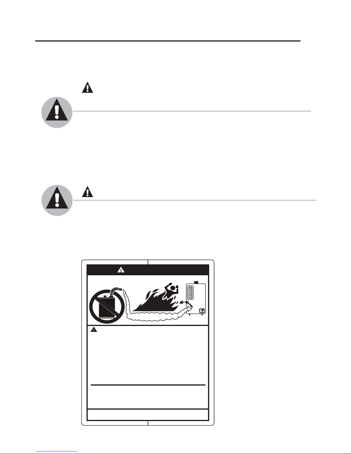
DANGER
FLAMMABLES
Vapors from flammable
liquids will explode and
catch fire causing death or
severe burns.
Do not use or store flammable
products such as gasoline,
solvents or adhesives in the
same room or area near the
water heater.
Keep flammable products:
1. far away from heater,
2. in approved containers,
3. tightly closed and
4. out of children's reach.
Installation:
Do not install water heater
where flammable products will
be stored or used unless the
main burner flame is at least
Read and follow water heater warnings and instructions. If
owners manual is missing, contact the retailer or manufacturer.
Flammable Vapors
Water he ater has a main
burner flame.
The main burner flame:
1. which c an come on
at any time and
2. will ignite flammable
vapo rs.
Vapors:
1. cannot be seen,
2. are heavier than air,
3. go a long way on the
floo r and
4. can be carried from
other r ooms to the
main burner flame by
air currents.
18" above the floor. This will
reduce, but not eliminate, the
risk of vapors being ignited
by the main burner flame.
3

!
IMPORTANT SAFETY INFORMATION
READ ALL INSTRUCTIONS BEFORE USING.
DANGER!
WATER TEMPERATURE SETTING
Safety and energy conservation are factors to be considered when selecting the water
temperature setting of a water heater’s remote control. Water temperatures above
125°F (52°C) can cause severe burns or death from scalding. Be sure to read and follow
the warnings outlined on the label pictured below.
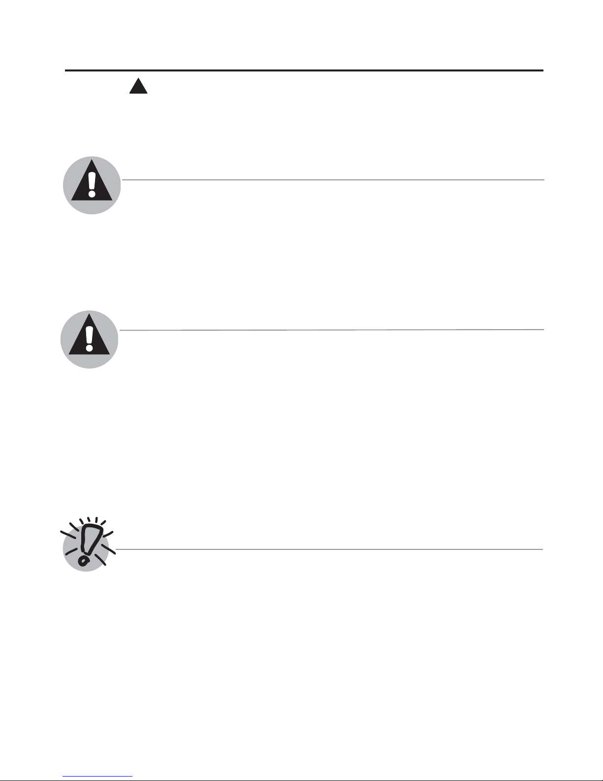
Time/Temperature Relationship in Scalds
!
DANGER
HOT
BURN
Water temperature over 125°
can
cause severe burns
instantly or
Children, disabled and elderly are
at highest risk of being scalded.
See instruction manual before
setting temperature at water
heater.
Feel water before bathing or
showering.
Temperature limiting valves are
available, see manual.
death from scalds.
F (52°C)
Water Temperature Time To Produce a Serious Burn
120°F (49°C) More than 5 minutes
125°F (52°C) 1
130°F (54°C) About 30 seconds
135°F (57°C) About 10 seconds
140°F (60°C) Less than 5 seconds
145°F (63°C) Less than 3 seconds
150°F (66°C) About 1
155°F (68°C) About 1 second
Table courtesy of Shriners Burn Institute
1
/2 to 2 minutes
1
/2 seconds
The chart shown above may be used as a guide in
determining the proper water temperature for your home.
!
DANGER: Households with small children, disabled
or elderly persons may require a 120°F (49°C) or lower
temperature setting to prevent contact with “HOT” water.
Maximum water temperature occurs while burner is on.
To find water temperature being delivered, turn on a hot
water faucet and place a thermometer in the water stream
and read the thermometer. (See page 22 & 23 for more
details.)
The temperature of the water at the outlet of the water
heater can be regulated by setting the temperature on
Remote Control. The remote control was set at 100°F
(38°C) before it was shipped from the factory.
Notice:
Display
PRIORITY
shows
°F only.
Higher (Hotter) Lower (Cooler)
85
100 102 104 106 108 110 112 114 116 118 120*
29
38 39 40 41 42 43 44 46 47 48 49*
°F
POWER
125 130 135 140 150 160 170 185
52 54 57 60 66 71 77 85 °C
* Temperatures 85°F(29°C) and above 120°F (49°C)
can be achieved with the Main (UMC-117) remote
control. See page 30 & 31 for minimum and
maximum temperature adjustment.
4
ON/OFF
The diagram to the bottom left illustrates the Remote
Control and how to adjust the water temperature.
Notice: The factory setting allows operating temperatures
between 100°F (38°C) and 120°F (49°C). Temperatures
of 85°F (29°C) can be achieved with the Bath (USC-117
or USC2-117) remote control. Only qualified service
personnel should perform this adjustment. Only factory
authorized remote control(s) should be used.
Notice: When this water heater is supplying general
purpose hot water requirements for use by individuals,
a thermostatically controlled mixing valve for reducing
point of use water temperature is recommended to reduce
the risk of scald injury. Contact a licensed plumber or the
local plumbing authority for further information.
°F
Notice: Only commercial products can achieve
temperatures up to 185° (85° C).

DANGER!
NATURAL GAS AND LIQUEFIED PETROLEUM MODELS
Both LP and natural gas have an odorant added to aid in detecting a gas leak. Some
people may not physically be able to smell or recognize this odorant. If you are unsure or
unfamiliar with the smell of LP or natural gas, ask the gas supplier. Other conditions, such as
“odorant fade”, which causes the odorant to diminish in intensity, can also hide or camouflage
a gas leak.
Water heaters utilizing LP gas are different
from natural gas models. A natural gas
water heater will not function safely on LP
gas and vice versa.
No attempt should ever be made to
convert the water heater from natural gas
to LP gas. To avoid possible equipment
damage, personal injury or fire, do not
connect the water heater to a fuel type not
in accordance with the unit data plate;
propane for propane units and natural gas
for natural gas units. These units are not
certified for any other fuel type.
LP appliances should not be installed below
grade (for example, in a basement) if such
installation is prohibited by federal, state
and/or local laws, rules, regulations or
customs.
Notice: If a gas leak is present or suspected:
Do not attempt to find the cause yourself.
Do not try to light any appliance.
Do not touch any electrical switch.
Do not use any phone in your building.
Leave the building immediately and make
sure your family and pets leave also.
Leave the doors open for ventilation and
contact the gas supplier, a qualified service
agency or the fire department.
Stay away from the building until the
service call has been made, the leak is
corrected and a qualified agency has
determined the area to be safe.
Propane or LP gas must be used with great
caution. It is heavier than air and will
collect first in lower areas, making it hard
to detect at nose level.
Before attempting to light the water heater,
make sure to look and smell for gas leaks.
Use a soapy solution to check all gas fittings
and connections. Bubbling at a connection
indicates a leak that must be corrected.
When smelling to detect a gas leak, be sure
to sniff near the floor also.
Gas detectors are recommended in LP
and natural gas applications and their
installation should be in accordance
with the detector manufacturer’s
recommendations and/or local laws,
rules, regulations or customs.
It is recommended that more than one
method, such as soapy solution, gas
detectors, etc., be used to detect leaks
in gas applications.
5
IMPORTANT SAFETY INFORMATION
READ ALL INSTRUCTIONS BEFORE USING.
!
WARNING!
For your safety, the information in this manual must be followed to minimize the risk
of fire or explosion, electric shock, or to prevent property damage, personal injury or
loss of life.
FOR INSTALLATIONS IN THE STATE OF CALIFORNIA
California Law requires that water heaters must be braced, anchored or strapped to resist
falling or horizontal displacement due to earthquake motions. For water heaters up to 52
gallon capacity, a brochure with generic earthquake bracing instructions can be obtained from:
Office of the State Architect, 1102 Q Street, Suite 5100, Sacramento, CA 95814 or you may call
916-445-8100 or ask a water heater dealer.
However, applicable local codes shall govern installation. For residential water heaters
of a capacity greater than 52 gallons or tankless-style, consult the local building jurisdiction
code for acceptable bracing procedures.
SAFETY PRECAUTIONS
Have the installer show you the location of the gas shut-off valve and how to shut it off
if necessary. Turn off the manual shut-off valve if the water heater has been subjected
to overheating, fire, flood, physical damage or if the gas supply fails to shut off.
Read this manual entirely before installing
or operating the water heater.
Use this appliance only for its intended
purpose as described in this Use and Care
Manual.
Be sure your appliance is properly installed
in accordance with local codes and the
provided installation instructions.
Do not attempt to repair or replace any
part of your water heater unless it is
specifically recommended in this manual.
All other servicing should be referred to a
qualified technician.
READ AND FOLLOW THIS SAFETY INFORMATION CAREFULLY.
SAVE THESE INSTRUCTIONS
6
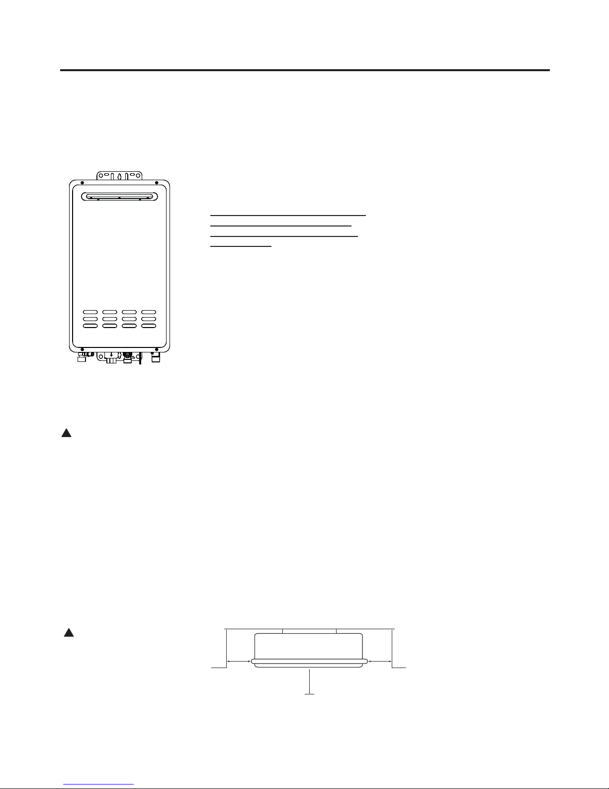
Installing the water heater:
!
min.
1/2 "
(1.3 cm)
min.
1/2 "
(1.3 cm)
min. 12" (30 cm)
(24" (61 cm) minimum is
recommended for service)
Front = 12" (30 cm)
Back = 0" (with support bracket)
Side = 1/2" (1.3 cm)
Bottom = 12" (30 cm)
!
This water heater must be installed in accordance with these instructions, local codes, utility company
requirements and/or in the absence of local codes, use the latest edition of the American National Standard/
National Fuel Gas Code. A copy can be purchased from either the American Gas Association, 400 North
Capitol Street Northwest, Washington, DC 20001 as ANSI standard Z223.1 or National Fire Protection
Association, 1 Batterymarch Park, Quincy, MA 02269 as NFPA 54. In Canada, the latest edition of the CSA
B149.1 Natural Gas and Propane Installation, and the Canadian Electrical Code, CSA C22.1 Part 1, in the
absence of local codes.
Location of the water heater
WARNING: Combustible
construction refers to
adjacent walls and ceilings
and should not be confused
with combustible or
flammable products and
materials. Combustible
and/or flammable products
and materials should never
be stored in the vicinity of
this or any gas appliance.
This water heater is for OUTDOOR
installation ONLY!
This water heater is an outdoor model
and must be mounted vertically. It
must not be installed indoors or in a
confined space.
The water heater should be installed
close to the most frequently used outlet
and its position chosen with safety and
service in mind.
Make sure people (particular children,
disabled, and elderly) will not touch the
hot water outlet or the flue terminal.
The flue terminal and air inlet must be
clear of obstruction and shrubbery.
The water heater should not be located
in an area where leakage of the heat
exchanger or connections will result
in damage to the area adjacent to it
or to lower floors of the structure.
A gas fired water heater or any other
appliance should not be installed in
a space where liquids which give off
flammable vapors are to be used or stored.
Such liquids include gasoline, but are not
limited to, LP gas (butane or propane),
paint or adhesives and their thinners,
solvents or removers.
Because of natural air movement in a room
or other enclosed space, flammable vapors
can be carried some distance from where
their liquids are being used or stored. The
open flame of the water heater’s main
burner can ignite these vapors, causing
an explosion or fire which may result in
severe burns, death or property damage.
The water heater must be located so it is not
subject to physical damage, for example, by
moving vehicles, area flooding, etc.
The water heater should be installed
vertically with the water, gas and power
connections on the underside pointing
toward the ground.
Failure to properly install the water heater
outdoors as outlined in this manual can
result in unsafe operation.
Hot and cold water lines should be insulated
to conserve water and energy.
The water heater and water lines should
be protected from exposure to freezing
temperatures.
Do not install water heater where subject
to vibrations.
Do not install the water heater in
Recreational Vehicles, Mobile Homes,
Boats and other Watercrafts.
Do not install the water heater near
vents for heating or cooling. A minimum
of 4 feet should be maintained.
Minimum clearance from combustible
and noncombustible construction is
1/2” (1.3 cm) sides, 0” rear (with support
bracket); 12” (30 cm) from the bottom;
12” (30 cm) from the front of the
water heater; (24” [61 cm] from front
recommended for servicing purposes).
If the clearances stated on the Instruction/
Warning Label, located on the front panel
of the heater differ, install the water
heater according to the clearances stated
on the label.
CAUTION:
Protect plastic, paint or
other items sensitive to heat
using non-combustible
insulation if these are
exposed to the flue exhaust
even though they may be
more than 24” (61 cm) away
from the water heater.
Minimum Clearance from Combustible and
Non-Combustible Construction.
Top: Do not install this water
heater under an overhang less
than 36” (91 cm) from its top.
The area under the overhang
must be open on 3 sides.
7

Installing the water heater:
!
Proper operation of the water heater requires air for combustion and ventilation. Provisions for combustion and ventilation air must comply with referenced codes and standards.
Combustion and Ventilation Air
NOTICE: The water heater
should not be installed near
an air supply containing
halogenated hydrocarbons.
This water heater is for OUTDOOR
installation ONLY.
DANGER: It must NOT be
installed indoors or in a confi ned
space.
Corrosive Atmospheres
The air in beauty shops, dry cleaning
establishments, photo processing labs,
and storage areas for liquid and powdered
bleaches or swimming pool chemicals
often contains such halogenated
hydrocarbons.
An air supply containing halogenated
hydrocarbons may be safe to breathe,
but when it passes through a gas flame,
corrosive elements are released that
will shorten the life of any gas burning
appliance.
Propellants from common spray cans
or gas leaks from A/C and refrigeration
equipment are highly corrosive after
passing through a flame.
The water heater warranty is voided when
failure of the heater is due to operation in
a corrosive atmosphere.
Inspect Shipment
Inspect the water heater for possible damage. Check the markings on the rating plate of
the water heater to be certain the type of gas supplied corresponds to the water heater
requirements. Verify all included parts are present (see below).
U se & Care M anual
Wi th Installation Instructions for the I nstalle r
R esidential G as
T ankless
W ater Heaters
W arning: This water heater is not suitable for
use in manufactur ed (mobile) homes!
The purpose of this manual is twofold: one, to pr ovide the installer with
the basic dir ections and re commendations for the pr oper installation and
adjustment of the water heater; and two, to the owner–operator , to
PRIORITY
°F
POWER
ON/OFF
Remote Control
Assembly Kit
Wood Screw x 5pcs.
Washer x 4 pcs.
explain the featur es, operation, safety pr ecautions, maintenance and
tr oubleshooting of the water heater . This manual also includes a parts
list.
It is imperative that all persons who ar e expected to install, operate or
adjust this water heater r ead the instructions car efully so they may
understand how to perform these operations. If you don’t understand
these instructions or any terms within it, seek pr ofessional advice.
Any questions r egarding the operation, maintenance, service or
warranty of this water heater should be dir ected to the selle rf ro m whom
it was pur chased. If additional information is re quir ed, r efer to the
section on How to Obtain Service Assistance.
Do not destr oy this manual. Please r ead c ar efully and keep in a safe
place for futur e r efer ence.
Recognize this symbol as an indication of Important Safety
!
Information!
C alifornia P r oposition 65 W arning: This pr oduct contains
!
chemicals known to the S tate of California to cause cancer , birth
defects or other r epr oductive harm.
W ARNING: If the information in these instructions is not followed exactly ,
!
a fir e or explosion may r esult causing pr operty damage, personal injury o r death.
!
FOR YOUR SAFETY!
l If you cannot r each your gas supplier , call
— Do not stor e or use gasoline or other
the fir e department.
flammable vapors or liquids or other
combustible materials in the vicinity of this or
l Do not r eturn to your home until authorized
any other appliance. To do so may r esult in an
by the gas supplier or fir e department.
explosion or fir e.
— Impr oper installation, adjustment,
alteration, service or maintenance can cause
— WHA TT O DO IF YOU SMELL GAS
pr operty damage, personal injury , or death .
lDo not try to light any appliance.
Refer to this manual. Installation and servic e
l Do not touch any electrical switch; do not
must be performed by a qualified installer ,
use any phone in your building.
service agency or the gas supplier .
l Immediately call your gas supplier fr om a
neighbor ’s phone. Follow the gas
supplier ’s instructions.
I
S
G
E
N
D
Printed in US A
T ankless Unit
C
E
D
R
E
I
T
F
I
®
Use & Care Manual
Manual Appliance
Gas Shut-off Valve
8
D
V
V
E
F
IX
ED
C
L
OSED
O
P
E
R
ABL
E
O
P
E
RA
B
LE
FIXE
D
CLO
S
ED
v
v
B
L
F
C
B
v
v
v
X
B
B
B
A
J
B
I
H
X
v
M
K
v
G
A
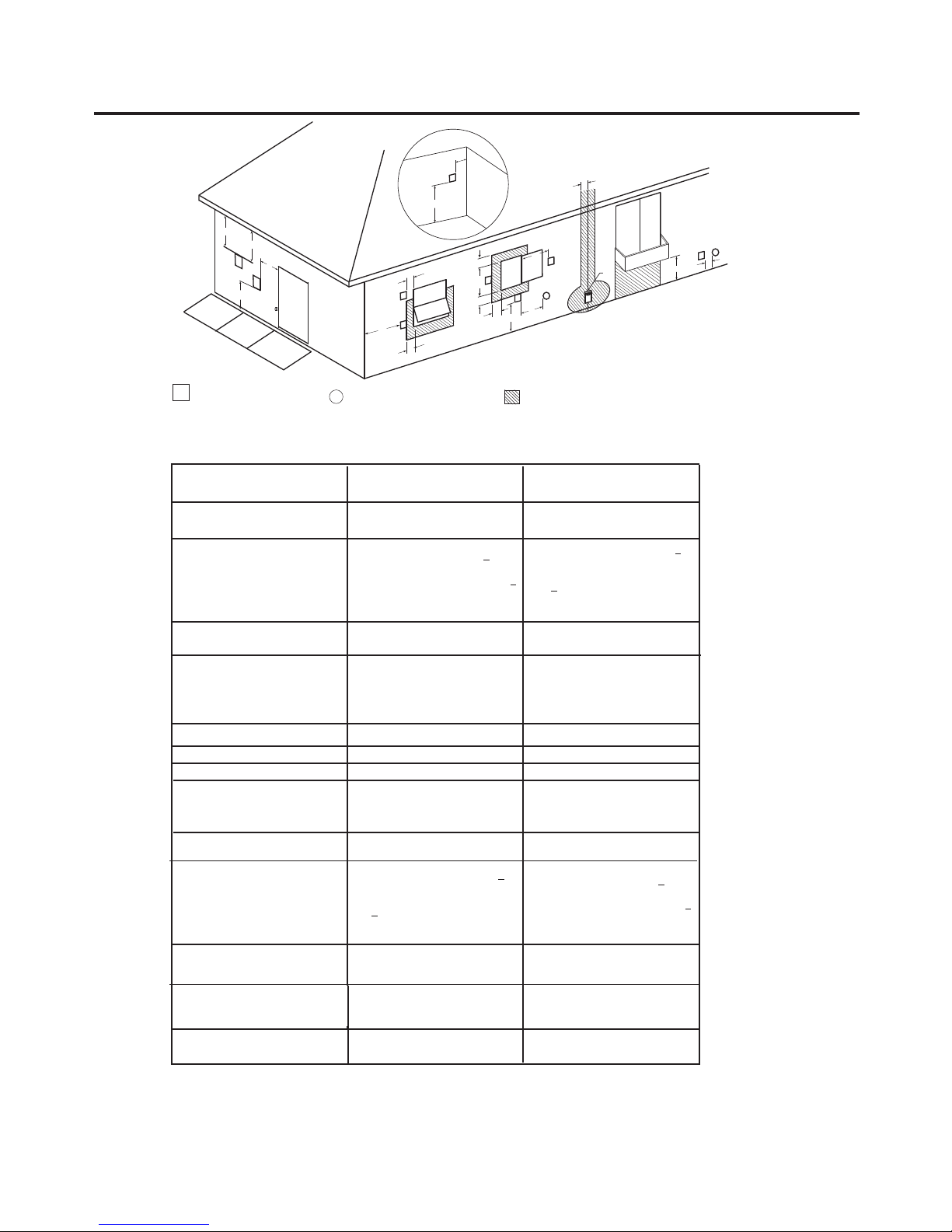
VENT TERMINAL
V
Horizontal Vent Terminal Location
The following information should be used for determining the proper location of the vent terminal
for indoor and outdoor tankless water heaters.
A= Clearance above grade, veranda,
porch, deck or balcony.
B= Clearance to window or door that
may be opened.
C= Clearance to permanently closed
window.
D= Vertical Clearance to ventilated
soffit located above the terminal
within a horizontal distance of 2
feet (61 cm) from the center line of
the terminal.
E= Clearance to unventilated soffit.
F= Clearance to outside corner.
G= Clearance to corner.
H = Clearance to each side of center line
extended meter/regulator assembly.
above
I = Clearance to service regulator vent
outlet.
J = Clearance to nonmechanical air
supply inlet to the combustion
air inlet to any building or other
appliance.
K = Clearance to mechanical air supply
inlet.
L = Clearance above paved sidewalk or
paved driveway
property.
M = Clearance under veranda, porch,
deck or balcony.
1 In accordance with current CSA-B149.1 Installation Codes.
2 In accordance with current ANSI Z223.1/ NFPA 54 National Fuel Gas Code.
† A vent shall not terminate directly above a sidewalk or paved driveway that is located between two single family
dwellings and serves both dwellings.
* For clearances not specified in ANSI 223.1/NFPA 54 or CSA-B149.12, one of the following shall be indicated:
a) A minmum clearance value determined by testing in accordance with section 2.20, or;
b) A reference to the following footnote: "Clearance in accordance with local installtion codes and the require ments of the gas supplier."
located on public
AIR SUPPLY INLET
X
Canadian Installations
Outdoor
12 inches (30 cm) above anticipated
6 inches (15 cm) for appliances < 10,000
Btuh (3 kW), 12 inches (30 cm) for
appliances > 10,000 Btuh (3kW) and <
100,000 Btuh (30kW), 36 inches (91 cm)
for appliances > 100,000 Btuh (30kW).
3 feet (91 cm) within a height 15 feet
(4.57 m) above the meter/regulator
6 inches (15 cm) for appliances <
10,000 Btuh (3 kW), 12 inches (30 cm)
for appliances > 10,000 Btuh (3kW)
and < 100,000 Btuh (30kW), 36 inches
(91 cm) for appliances > 100,000 Btuh
snow level.
*
*
*
*
*
assembly.
3 feet (91 cm)
(30kW).
6 feet (1.83 m)
7 feet (2.13m) †
Not Allowed
AREA WHERE TERMINAL IS NOT PERMITTED
1
US Installations
Outdoor
12 inches (30 cm) above anticipated
10,000 Btuh (3 kW), 9 inches (23 cm)
for appliances > 10,000 Btuh (3kW)
and < 50,000 Btuh (15kW), 12 inches
(30 cm) for appliances > 50,000 Btuh
snow level.
6 inches (15 cm) for appliances <
(15kW).
*
*
*
*
*
*
*
6 inches (15 cm) for appliances < 10,000
Btuh (3 kW), 9 inches (23 cm) for
appliances > 10,000 Btuh (3kW) and <
50,000 Btuh (15kW), 12 inches (30 cm)
for appliances > 50,000 Btuh (15kW).
3 feet (91 cm) above if within 10 feet
(3 m)
horizontally.
*
Not Allowed
2
9

Installing the water heater:
(1.8 m)
If soffit vent is too close,
block off and install new
vent at another location
Inside
corner
Caulk
Caulk
Caulk
6' (1.8 m)
caulk zone or
to edge of
window etc., starting
within 6' (1.8 m)
Rising moisture will collect under eaves
4'
6' (1.8 m) caulk
zone
6'
(1.2 m)
12” (30 cm)
Outdoor Water Heater
WARNING: Moisture in the flue gas will condense as
it leaves the vent terminal. In cold weather this condensate
can freeze on the exterior wall, under the eaves and on
surrounding objects. Some discoloration on the exterior of
the building is to be expected. However, improper location
or installation can result in severe damage to the structure
or exterior finish of the building.
Additional Considerations
Do NOT install vent terminal under any patio or deck.
To help prevent moisture from freezing on walls and under
eaves, do not locate vent terminal on the side of a build ing with
prevailing winter winds.
To help prevent water lines from freezing, do not locate vent
terminal on the side of a building with prevailing winter winds.
Do NOT locate vent terminal too close to shrubbery, as flue gases
may damage them.
All painted surfaces should be primed to lessen the chance of
physical damage. Painted surfaces will require maintenance.
Guard vent against accidental contact with people and pets.
Install outdoor water heater such that air inlet and flue outlet is
above anticipated snow level.
10
Installing the water heater:
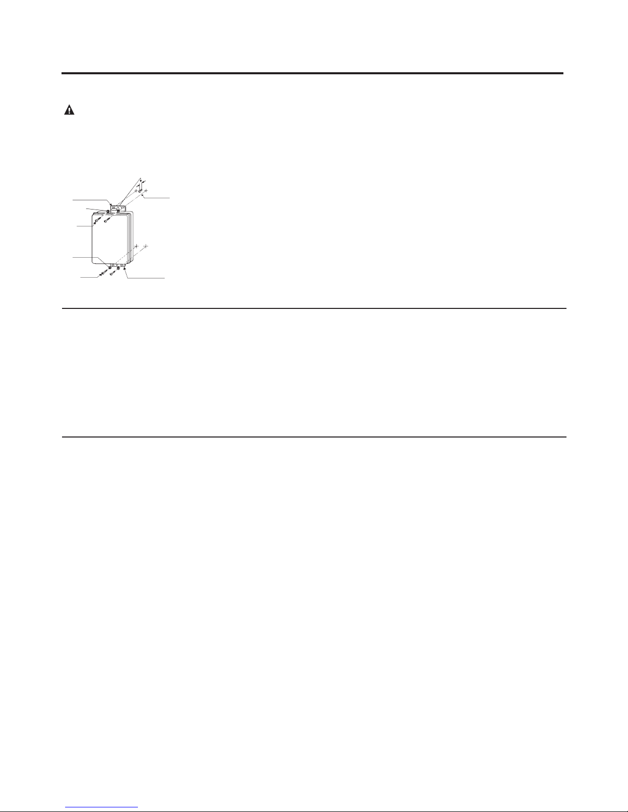
Mounting the Water Heater
CAUTION:
Reinforcement of the wall is
required in case the wall is
not strong enough to hold
the appliance.
1/8" (.32 cm)
Clearance
Upper Bracket
Was he r
Wood
Screw
Was he r
Wood
Screw
Wood
Screw
Lower Bracket
Make sure the location of the appliance allows
for easy access and operation.
Wall studs should be utilized when mounting
the water heater to the wall. Alternately, a
suitable piece of wood may be placed inside
or outside of the wall to span the distance
between the wall studs. Fasten the water
heater mounting brackets to the wood.
In case of dry wall or concrete wall, use
drywall anchors or lag bolts.
Thermal Expansion
A thermal expansion tank will be required if
the water heater is installed in a closed loop
system to prevent damage to heater, related
piping and relief valve. Replacing the relief
valve will not correct the problem! The
expansion tank is designed with an air cushion
built in that compresses as the system pressure
increases, thereby relieving the over pressure
The water heater requires 120VAC/60Hz.
Have a receptacle with ground terminal near
the water heater. A power supply cord is not
supplied with the water heater. Install a wood
screw for the upper bracket with a clearance
of 1/8” (.32 cm) between the wall and the
screw head. Hang the center of the upper
bracket on the screw.
Using a wood screw and a washer, affix the
lower bracket to the wall (Left and Right).
Repeat to affix the top bracket.
condition and eliminating the repeated
operation of the relief valve. Other methods
of controlling thermal expansion are also
available. Contact your installing contractor,
water supplier or plumbing inspector for
additional information regarding this subject.
IMPORTANT: Do not
apply heat to the HOT or
COLD water connections. If
sweat connections are used,
sweat tubing to adapter
before fitting adapter to
the water connections on
heater. Any heat applied
to the water supply fittings
will permanently damage
the internal components
of the water heater.
Notice: Due to cold
environments, ice may
potentially accumulate at
the water connections. In
this case, please insert the
power cord of the water
heater into an electrical
outlet. The ice should melt
within approximately 10
minutes and at this time the
water connections can be
made.
Water Supply Connections
Plumbing should be carried out by a qualified
plumber in accordance with local codes.
Use approved plumbing materials only.
The diameter of the pipe lines should be a
minimum of 3/4”.
To conserve energy and to prevent freezing,
insulate both cold and hot water supply
lines. DO NOT cover the drain or pressure
relief valve.
To ensure proper operation of the water
heater, the following water pressure guidelines
should be followed:
Operation of the water heater requires the
minimum water pressure of 14 psi (97 kPa)
and a minimum water flow rate of 0.66
gpm (2.5 lpm).
A water pressure of 40 psi (276 kPa) is
required to achieve maximum flow rate.
To maintain proper performance, ensure
sufficient water supply pressure. The
Required Water Pressure = Min. Operating
Water Pressure (14 psi [97 kPa]) + Pipe
Pressure Loss + Faucet and Shower
Pressure Loss + Safety Margin (more than
5 psi [34 kPa]).
To supply hot water to upper floors,
additional water pressure (0.44 psi/ft
[10 kPa/m]) must be ensured. The
measurement should be calculated by the
distance between the water inlet of the
water heater (ground level) to the hot
water faucet (upper floor level).
Well water systems should be set to ensure
a minimum system pressure of 40 psi (276
kPa). The pressure should remain stable
during the operation of the water heater.
When the water is supplied from a water
supply tank, the height of the tank and the
diameter of the pipes and their relation
to water pressure should be taken into
consideration. Gravity water pressure is
not recommended.
11
 Loading...