

Paloma PH2-28R OFP, PH2-25R OFN, PH2-20R OFP, PH2-25R OFP, PH2-28R OFN Engineering Handbook
...Page 1
R
r
Tankless Gas Water Heaters
Mid Effi ciency Models
PH2-20R OFN, PH2-25R OFN & PH2-28R OFN (Outdoor Natural Gas Models)
PH2-20R OFP, PH2-25R OFP & PH2-28R OFP (Outdoor L.P. Gas Models)
PH2-20R DVSN, PH2-25R DVSN & PH2-28R DVSN
(Indoor Direct Vent Natural Gas Models)
PH2-20R DVSP, PH2-25R DVSP & PH2-28R DVSP
(Indoor Direct Vent L.P. Gas Models)
High Effi ciency Condensing Models
PHH-25ROFN & PHH-32ROFN (Outdoor Natural Gas Models)
PHH-25ROFP & PHH-32ROFP (Outdoor L.P. Gas Models)
PHH-25RDVN & PHH-32RDVN (Indoor Direct Vent Natural Gas Models)
PHH-25RDVP & PHH-32RDVP (Indoor Direct Vent L.P. Gas Models)
Outdoor Water Heater
PH2-20, 25 & 28ROF
Indoor Direct Vent Water Heate
PH2-20, 25 & 28RDVS
Engineering Handbook
Outdoor Water Heater
PHH-25ROF & PHH-32ROF
I
S
E
D
C
E
R
T
F
I
Indoor Direct Vent Water Heater
PHH-25RDV & PHH-32RDV
G
N
D
E
I
®
CERTIFIED
R
Page 2

2 | Page SVC 820 Tankless Gas Trouble Shooting Manual
2
TABLE OF CONTENTS
General Information
Specifications 4
Sequence of Operations 5
1. Ignition Sequence 6
2. Monitoring Sequence 7
3. Shutdown Sequence 8
Error Code Table 9
Components “Callouts” 15
Maintenance Mode “How To” 16
Control Board “Callouts” 18
Reset Procedure 21
Clearing Fault History 21
Error Code Diagnostics
No Error Code & No Hot Water 22
P1 Warning Code 23
1L Warning Code 24
03 Error Code 25
05 Warning Code 26
10 Warning Code 29
11 Error Code 33
Gas Supply & Venting 33
Igniter Rod (Spark is NOT visible) 34
Flame Rod (Flame IS visible) 36
Gas Control Valve (Spark IS visible; Flame is NOT visible) 38
Control Board 40
12 Error Code 43
Gas Supply & Venting 43
Flame Rod(s) 44
13 Error Code 47
Venting 47
Ground 47
Flame Rod(s) 48
14 Error Code 50
15 Error Code 53
16 Error Code 54
24 Error Code 56
29 Error Code 59
31 Error Code 60
32 Error Code 62
Page 3

SVC 820-Tankless Gas Trouble Shooting Manual Page | 3
3
TABLE OF CONTENTS
33 Error Code 64
34 Error Code 66
35 Error Code 68
51 Error Code 70
52 Error Code 72
61 Error Code 74
65 Error Code 76
66 Error Code 78
71 Error Code 80
72 Error Code 82
76 Error Code 84
79 Error Code 86
80 Error Code 88
82 Error Code 90
90 Error Code 91
92 Warning Code 92
93 Error Code 92
99 Error Code 93
Page 4
4 | Page SVC 820 Tankless Gas Trouble Shooting Manual
4
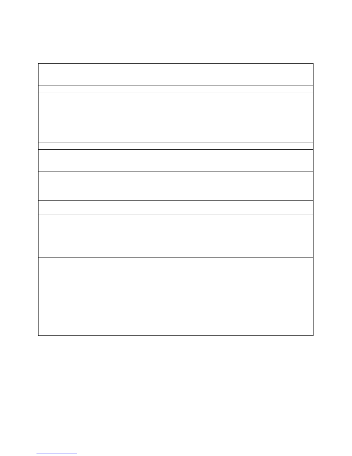
Specifications common to all models
Model See specification sheets for current models and specs
Purpose Domestic Hot Water (DHW) supply for showers, cleaning, and laundry
Rated Gas Input Btu/Hr.) See specification sheets for current models and specs
Dimensions See specification sheets for current models and specs
Installation
Working Water Pressure 14 PSI minimum; 150 PSI maximum
Minimum Water Flow 0.4 GPM to activate burner; can be reduced to .26 GPM once burner is activated
Maximum Water Flow Based on 35 degree rise; See specification sheets for current models and specs
Gas Connection 3/4” NPT Male
Water Connection 3/4" NPT Male
Vent Size Mid Efficiency: 3”/5” Concentric Vent
Max Vent Length See Use & Care Manual for each product type
Inlet Gas Pressure Natural Gas: Minimum 4.0” w.c. Maximum 10.5” w.c.
Hot Water Supply
Temperatures
Electrical
Safety Devices
Freeze Protection Minus 30F (Without Wind-Chill Factor) with power applied
Remote Control
Indoor Wall Mounting : Can be vented horizontally or vertically
Outdoor Wall Mounting : Venting not required
Mid Efficiency : ONLY uses Stainless steel (Category III; 316L Certified)
concentric venting for indoor installation
High Efficiency: Uses PVC; CPVC; ABS; or Stainless Steel (Category III; 316L
Certified) venting for indoor installation
High Efficiency: 2” or 3” Two Pipe Venting (optional concentric vent termination)
L.P. Gas : Minimum 8.0” w.c. Maximum 14.0” w.c.
Factory Setting: 85F – 140F (Up to 140 with Override Adjustment)
Commercial Setting: Up to 185F via program chip
Rating: 120 VAC/60Hz, 3 Amps
Wire : Indoor Models - 3 Prong (Edison) Power Supply Cord
Outdoor Models – require field wiring
Fuse : 3A Fuse x 2 (line voltage)
Flame Rods
Overheat Film Wrap for Heat Exchanger
Heat Exchanger Thermistor (Boiling Point Safety)
Electronic Burner and Combustion Monitoring and Control
Standard: Main Remote Control UMC-117 (included)
Optional: Bath Remote Control USC1-117 – 120 F Max Limit
Optional: Second Bath Remote USC2-117 – 120 F Max Limit
Only one of each type remote above can be installed on a single unit
Only one of each type remote above can be installed on multiple manifold units
Page 5
SVC 820-Tankless Gas Trouble Shooting Manual Page | 5
5
o
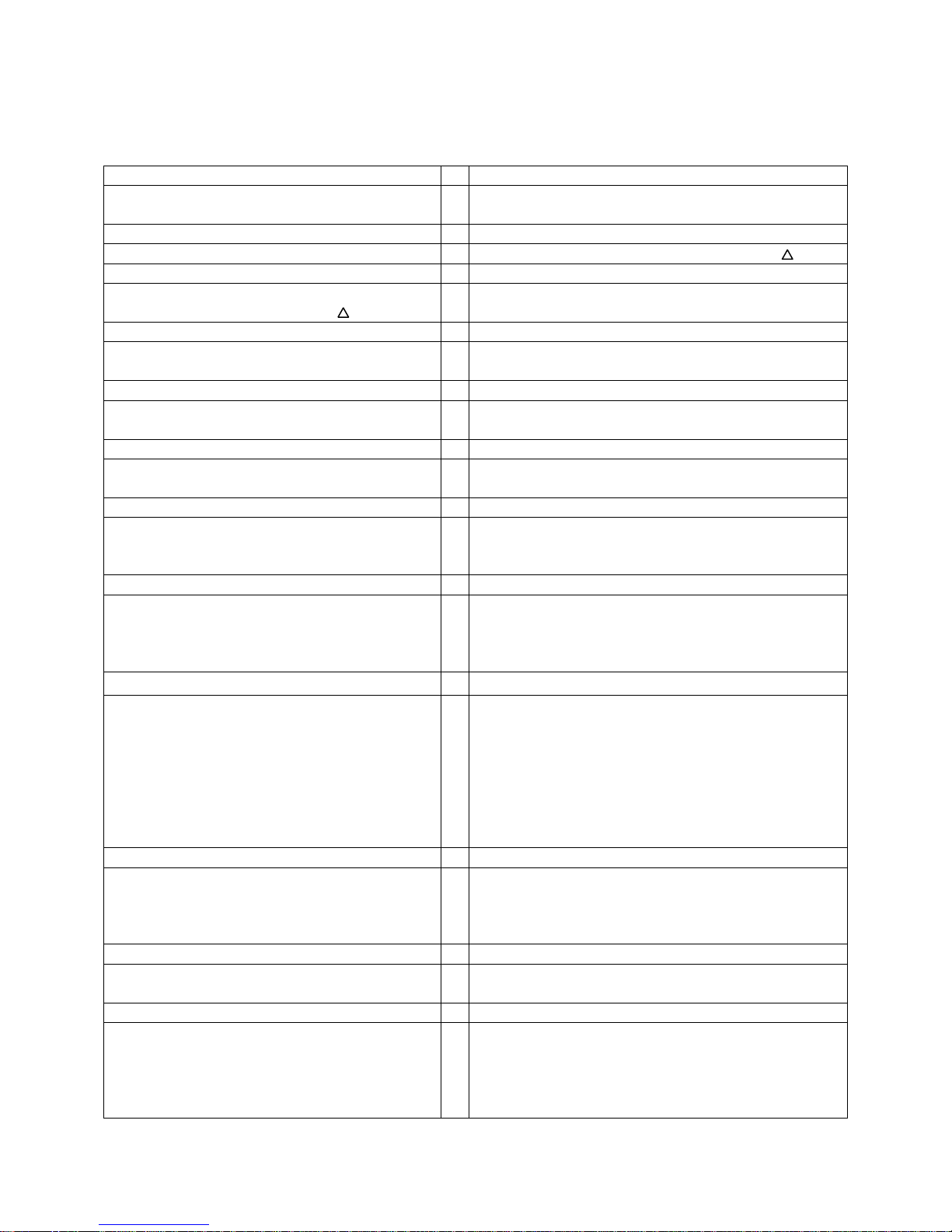
Sequence of Operations
ACTION EXPLANATION
Hot water faucet is open creating a demand Hot water draw initiates water flow thru the water
heater
Water flows thru the Water Flow Sensor Minimum flow rate of .4 GPM to activate @ 35
Control Board senses the flow rate has reached a
minimum demand of .4 GPM@ 35
Blower Motor conducts a pre-purge Pre purge is designed to verify we have a clear and clean
The Proportional Gas Flow Regulator allows the
gas to flow to the main burner
Simultaneously, the Igniter Rod sparks and ignites
the main burner
After ignition, the Flame Rods sense and monitor
the flame and ensure proper combustion
The “In Use Indicator” on the remote control turns
“ON” (Red) and the “Priority Indicator” is Green
(multiple remote controls)
o
T
Control Board is the ‘brains’ of the machine and controls
all input and actions during sequence of operations
vent and supply oxygen to burner for proper ignition
Proportional Gas Flow Regulator initially opens to 75% of
BTU input
The Igniter Rod ignites the fuel in the main burner area.
All burners will fire initially
The purpose of the flame rods is to verify flame and
proper combustion. In the event of flame failure or
improper combustion, the unit will go into an error code
Main burner is now lit. The PCB goes thru a series of
calculations (input sensing) to balance out the cold-water
temperature, the thermostat setting, the hot outlet
temperature, and the BTU required to heat the water.
The Proportional Gas Flow Regulator continuously
adjusts the gas volume in order to maintain the
outlet temperature. The water flow sensor also
adjusts the proper amount of cold water mix flow
to supply a stable hot water temperature at all
times. A signal is also sent to the Blower Motor in
order to constantly maintain the correct
proportion between gas and air volumes
(Indoor Models Only) When the air intake is
blocked, or oxygen is not sufficient, the output of
the Flame Sensor changes
When the hot water tap is closed, the flow rate
signal from the water flow sensor stops
The Fan continues to run for a few minutes Purpose is to cool the heat exchanger, exhaust all
The PCB is constantly monitoring all of these inputs and
actions to ensure the outlet water temperature is within
1-5 degrees of thermostat setting. It also monitors the
BTU required to heat the cold water to the thermostat
setting and adjusts the gas valve accordingly
The PCB senses this change and controls the Fan and Gas
Valve in order to prevent imperfect combustion. If the
PCB cannot correct such condition, the unit will go into
an error code
Gas valve is closed. Main burner shuts off
combustions gases, and to maintain the burner chamber
charged with air for immediate ignition if there is
another hot water demand
T
Page 6
6
14 – OHL
False
33 – Outlet Thermistor
61
90: > 12 seconds
72: > 5 seconds
11: > 2 Ignition Attempts
Plug In
82 – Program Chip
6 | Page SVC 820 Tankless Gas Trouble Shooting Manual
Health
Check
71 – Gas Control Valve
79 – Blower Motor
76 – Remote Control
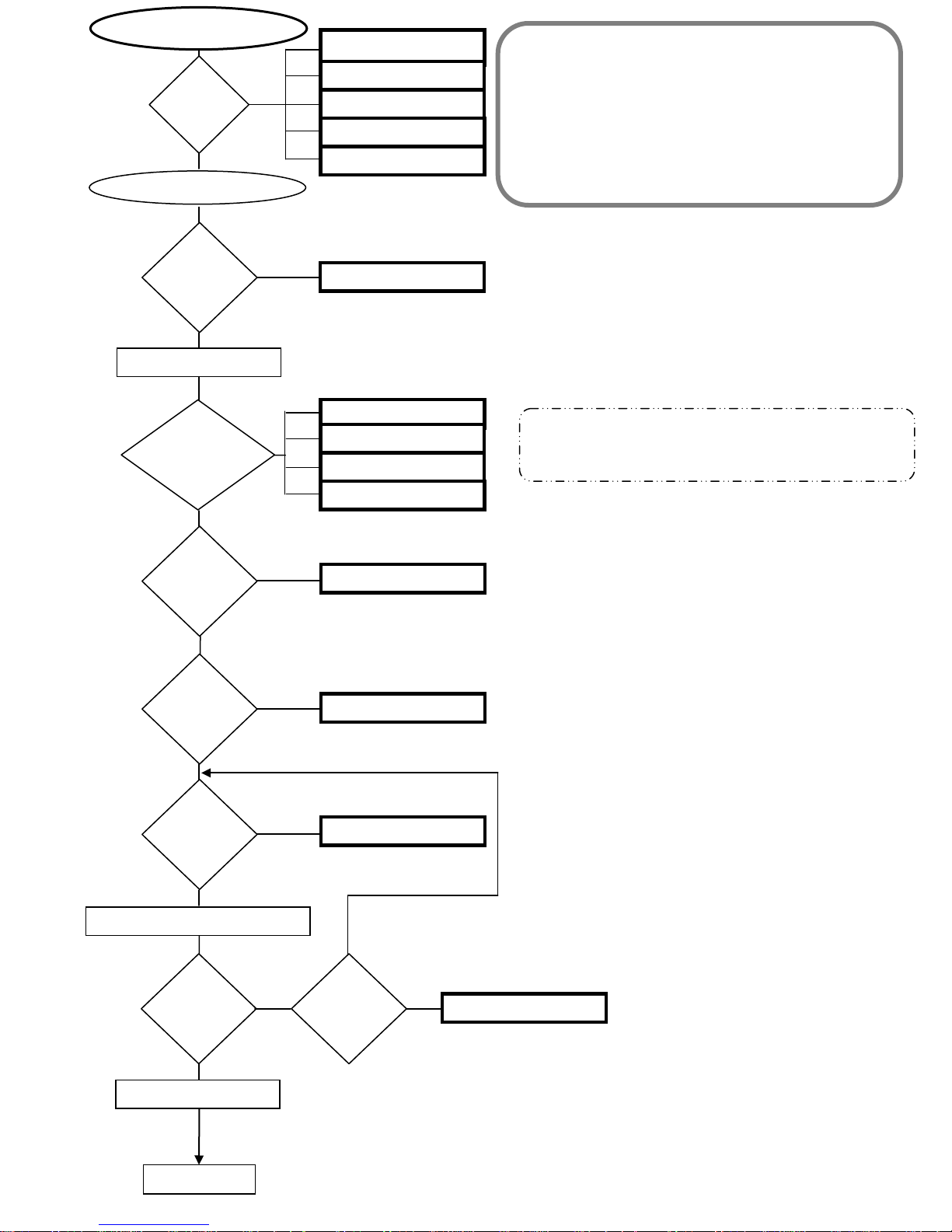
1. Ignition Sequence
2. Monitoring Sequence
SEQUENCE OF OPERATIONS:
Open Hot Water Tap
3. Shutdown Sequence
Up &
Down
Buttons
24: Activated > 20 Seconds
Blower On
Thermistors
Check
31 – Inlet Thermistor
32 – HE Thermistor
34 – Ambient Thermistor
Blower
Speed
1 – Ignition Sequence
Flue
Blockage
Flame
Gas Control Valve & Igniter Rod On
Detect
Flame
Igniter Rod Off
YES
1-2
Ignition
Attempt
NO
Next Page
Page 7
SVC 820-Tankless Gas Trouble Shooting Manual Page | 7
7
Ignition Failure
10 Warning Code Flashing
05 Warning Code Flashing
11
12
1-2 Ignition
too high
35
52
61
65
66
71
76
79
13
Imperfect
Combustion
Flow Chart
Alarm
No
Decrease of
Fan Motor
Ventilation
No
2 – Monitoring Sequence: while unit is in
operation
Yes Yes
Attempt to Re-Ignite
Yes
Flame Failure
Condensation Not Draining
OHL Activated
Hot Water > 207 Degrees F
for more than 15 seconds
Heat Exchanger > 207
Degrees F for more than 15
seconds
Outlet water temperature
29: Condensing Only
14
15
15
16
Attempts
No
Next Page
Gas Control Valve
Trouble with
Thermistor(s)
PGFR – Gas Control
29 34 33 32 31
Heat Exchanger
Outlet Temp Too
Low
Ambient
Thermistor
Valve
Communication
Trouble – Remote
Control
Blower Motor Water Control Body Bypass Assembly
Outlet Thermistor
Blower Motor
Current Not
Detected
Heat Exchanger
Thermistor
Flame Rod
Inlet Thermistor
Page 8
8 | Page SVC 820 Tankless Gas Trouble Shooting Manual
8
80: Gas Control Valve
51: Gas Control Valve
99
Close Hot Water Tap
3 – Shutdown Sequence
Gas Control Valve Off
Detect
Flame?
Checking
Blower
Motor
Unit in Stand-By mode
Yes (8 Seconds Later)
Page 9
SVC 820-Tankless Gas Trouble Shooting Manual Page | 9
9
Code
P1
Error Code
Fault Remedy
Flow Rate/Maintenance:
Nothing Happens When
No
Water Is Flowing Through
Code
Unit. (Control Board
Displays Water Temp)
Maintenance Warning:
Water Flow Too Low
(Unit Will Still Be
Operable; Minimum Flow
0.40 GPM To Activate @
o
) T
35
Maintenance:
Water Heater Has
1L
Buildup Of Lime/Scale
Deposits
1. Increase water flow rate or set higher temperature
2. New Installations: Ensure hot and cold water lines are not crossed
3. Check for plumbing crossover in the home
4. Clean water inlet filter
5. Check water flow sensor (may be jammed)
1. Check hot water tap flow (clean aerator if necessary)
2. Clean water inlet filter
3. Increase flow rate or set higher temperature
If maintenance requirements are met:
1. Check water flow sensor
1. Flush Heat Exchanger
2. High Altitude Installations: ensure proper altitude settings have been made
03 MIC 185, MIC 6, & EZ Link
Maintenance Warning:
Air Intake Or Vent
Exhaust May Be Blocked
(Unit Will Still Be
Operable)
05
Installation Warning:
The vent Pipes On The
Vent Termination May
Not Be Connected (Unit
Will Still Be Operable)
1. Check communications cable connection
2. Check # 4 dip switch setting is in the ‘ON’ position (Dip Set # 1 (Top), Dip
switch # 4 on the water heaters only)
1. Remove any vent blockage
2. Make sure venting meets all installation requirements
If maintenance requirements are met:
1. Check fan motor
Make sure all venting is properly sealed and meets all venting requirements (diameter;
vent lengths; venting material; venting obstructions; and all other installation
requirements as described in installation manual)
If installation requirements are met:
1. Check Blower Motor
Page 10

10 | Page SVC 820 Tankless Gas Trouble Shooting Manual
10
Maintenance:
10
Decrease Of Ventilation
Amount (Blower Motor)
Installation/Gas supply:
11
Ignition Failure
Gas supply/Installation/
Maintenance:
12
Flame Failure (Had Main
Burner, Then Lost It)
Clean any blockage in venting, Blower Motor, air intake
If maintenance requirements are met:
1. Check Blower Motor
1. Ensure you have gas to the appliance and valves are turned ‘ON’
2. Ensure gas type, gas pressure, and gas volume are correct
3. Bleed all air from gas lines
4. Ensure gas line, meter, and regulator are sized properly
5. Ensure appliance is properly grounded
If installation/gas supply requirements are met:
1. Check Gas Control valve for open or short circuits
2. Ensure Igniter Rod is operational
3. Check igniter/Flame Rod(s) and Igniter/Flame Rod(s) wiring harness for
damage
4. Check Control Board
5. Check Flame Rod Status
1. Ensure gas type and pressure is correct
2. Bleed all air from gas lines
3. Ensure Flame Rod wire(s) is connected
4. Check Flame Rod(s) for carbon build-up
5. Ensure gas line, meter, and regulator are sized properly
6. Ensure appliance is properly grounded
7. Check power supply for proper voltage and voltage drops
8. Disconnect and re-connect all wiring harnesses on Gas Control Valve and
Control Board
If gas supply/installation/maintenance requirements are met:
1. Check gas valves for open or short circuits
2. Check flame rod(s) and flame rod(s) wiring harness for damage
3. Check PCB
4. Check flame rod(s) status
Page 11
SVC 820-Tankless Gas Trouble Shooting Manual Page | 11
11
Ensure intake and exhaust venting meet all installation requirements (diameter; vent
lengths; venting material; venting obstructions; and all other requirements as
Indoor ONLY
Venting:
13
Flame Rod FL-2: Reads
Poor Or Improper
Combustion
described in the Use & Care manual {Make sure exhaust is not recirculating into fresh
air intake})
If venting requirements are met:
1. Remove any blockage from venting or from in front of vent termination
2. Verify altitude settings
3. Check Flame Rod FL-2
4. Check Blower Motor
Condensing only:
Maintenance:
Flue Temperature Too
High
14
Mid Efficiency &
Condensing:
Over Heat Limiter (OHL)
Fault
Maintenance:
Boiling Safety Device
(Heat Exchanger
15
temperature reached
207 F degrees for more
than 15 seconds)
Condensing Only:
1. Clean blockage in heat exchanger
2. Remove any blockage from Blower Motor and exhaust vent
Mid Efficiency & Condensing:
If ‘Condensing’ maintenance requirements are met:
1. Verify “U” connector is connected to Control Board
2. Verify wiring harness is connected to OHL
3. Check heat exchanger for cracks and/or separations
4. Inspect Overheat Wrap (Overheat wrap failure: Replace unit)
5. Check thermal overload sensor (condensing models only)
1. Flush Heat Exchanger (lime/scale buildup)
2. Check for closed water heater inlet valve or restrictions in cold water inlet
pipe (must be fully open)
3. On commercial water heater, lower set point temperature below 180
high altitudes
If maintenance requirements are met:
1. Check Heat Exchanger Thermistor
0
F at
Maintenance:
Outlet Water
16
Temperature Is Above
Remote Thermostat
Setting
If maintenance requirements are met:
1. Check for clogged Heat Exchanger
2. Check for restrictions in airflow around unit and vent terminal
1. Check Outlet Thermistor
2. Check Heat Exchanger Thermistor
3. Check gas valve
Page 12
12 | Page SVC 820 Tankless Gas Trouble Shooting Manual
12
Malfunction Of
24
Operational Switch
Condensing Only:
Maintenance:
Neutralizer Is clogged
29
Mid Efficiency &
Condensing:
Maintenance:
1. Turn off water. Disconnect Remote Control and retry
2. Verify unit is electrically grounded
3. Press MIN and MAX button on Control Board to reset
Condensing Only:
1. Ensure shipping cap for drain line is removed and drain line is not blocked
2. Clear all neutralizer drainage ports inside of unit
3. Clear neutralizer drainage line outside of unit
4. Clean air inlet screen
5. Clean heat exchanger fins
If maintenance requirements are met:
1. Check neutralizer water level electrode
Mid Efficiency & Condensing:
1. Clean air inlet screen
2. Clean heat exchanger fins
Heat Exchanger
Temperature Is Too Low
31 Inlet Thermistor
Heat Exchanger
32
Thermistor
Outgoing Water
33
Temperature Sensor
1. Check Thermistor wiring for damage
2. Check and clean scale from Thermistor
3. Ohm Thermistor
1. Check Thermistor wiring for damage
2. Check and clean scale from Thermistor
3. Ohm Thermistor
1. Check Thermistor wiring for damage
2. Check and clean scale from Thermistor
3. Ohm Thermistor
Page 13
SVC 820-Tankless Gas Trouble Shooting Manual Page | 13
13
1. Check Thermistor wiring for damage
2. Check and clean Ambient Thermistor
3. Ohm Thermistor
34 Ambient Thermistor
Improper Thermistor
35
Connection
51 Gas Control Valve
PGFR Valve
52
(Modulating Valve)
Installation/Maintenance:
61
Blower Motor
If wiring and component readings are normal:
1. Check for restrictions in airflow around unit and vent terminal
2. Ensure fan blade is tight on motor shaft and spins freely
1. Check that all Thermistors are secured to proper connections on Control
Board
2. Check that all quick connectors between Control Board and Thermistors
1. Check Gas Control Valve wiring harness for loose or damaged terminals
2. Ohm Gas Control Valve
1. Check PGFR Valve wiring harness for loose or damaged connections
2. Ohm PGFR Valve
1. Ensure Blower Motor will turn freely. Motor will operate with a small amount
of restriction
2. Check wiring harness to Motor for damaged and/or loose connections
3. Check venting length not to exceed max lengths and bends
65 Water Control Valve
66 Water Bypass Valve
71 Gas Control Valve
Flame Rod
72
(Detected False Flame)
1. Check Water Control Valve wiring harness for loose or damaged terminals
2. Check for proper voltage to Water Control Valve
1. Check Water Bypass Valve wiring harness for loose or damaged terminals
2. Check for proper voltage to water by-pass solenoid
1. Check Gas Control Valve wiring harness for loose or damaged terminals
2. Ohm Gas Control Valve
1. Ensure Flame Rod(s) is touching flame when unit fires
2. Check inside burner chamber for any foreign material blocking flame at Flame
Rod(s)
3. Check all wiring to Flame Rod for damage
4. Check Flame Rod for proper voltage
5. Remove Flame Rod and check, clean with steel wool
(Do not use sandpaper)
Page 14
14 | Page SVC 820 Tankless Gas Trouble Shooting Manual
14
1. Check Remote Control wiring for loose or damaged connections
2. Bypass Remote Control: connect Remote Control directly to remote
Communication Fault
76
With Remote Control
connection at bottom of the heater. Replace cable if found to be faulty
3. Remove water heater power cord from 3 prong outlet.
Remote Control. Plug heater back into supply and test heater without Remote
Control connected
Disconnect the
Blower Motor
79
Current Fault
80
&
Gas Control Valve
81
Installation:
82
Control Board Is Not
Programmed.
Maintenance/Installation:
90
Blocked Flue/Air Intake
Condensing Only:
Maintenance Warning:
92
Neutralizer Needs To Be
Replaced (Unit Will Still
Be Operable)
1. Ensure Blower Motor will turn freely. Motor will operate with a small amount
of restriction
2. Check Fan Motor for proper voltage and for water (condensation) damage
1. Ohm Gas Control Valve
2. Check voltage of all Flame Rods
Verify Program Chip is installed
Clean any blockage in Heat Exchanger, Blower Motor, inlet flue and exhaust flue
Replace Neutralizer
Condensing Only:
Maintenance:
93
Neutralizer Must Be
Replaced (Unit Will NOT
Operate)
Maintenance/Installation:
99
Blower Motor Cannot
Vent
Replace Neutralizer
1. Clear vent blockages
2. Check for blocked Heat Exchanger
Page 15
SVC 820-Tankless Gas Trouble Shooting Manual Page | 15
15
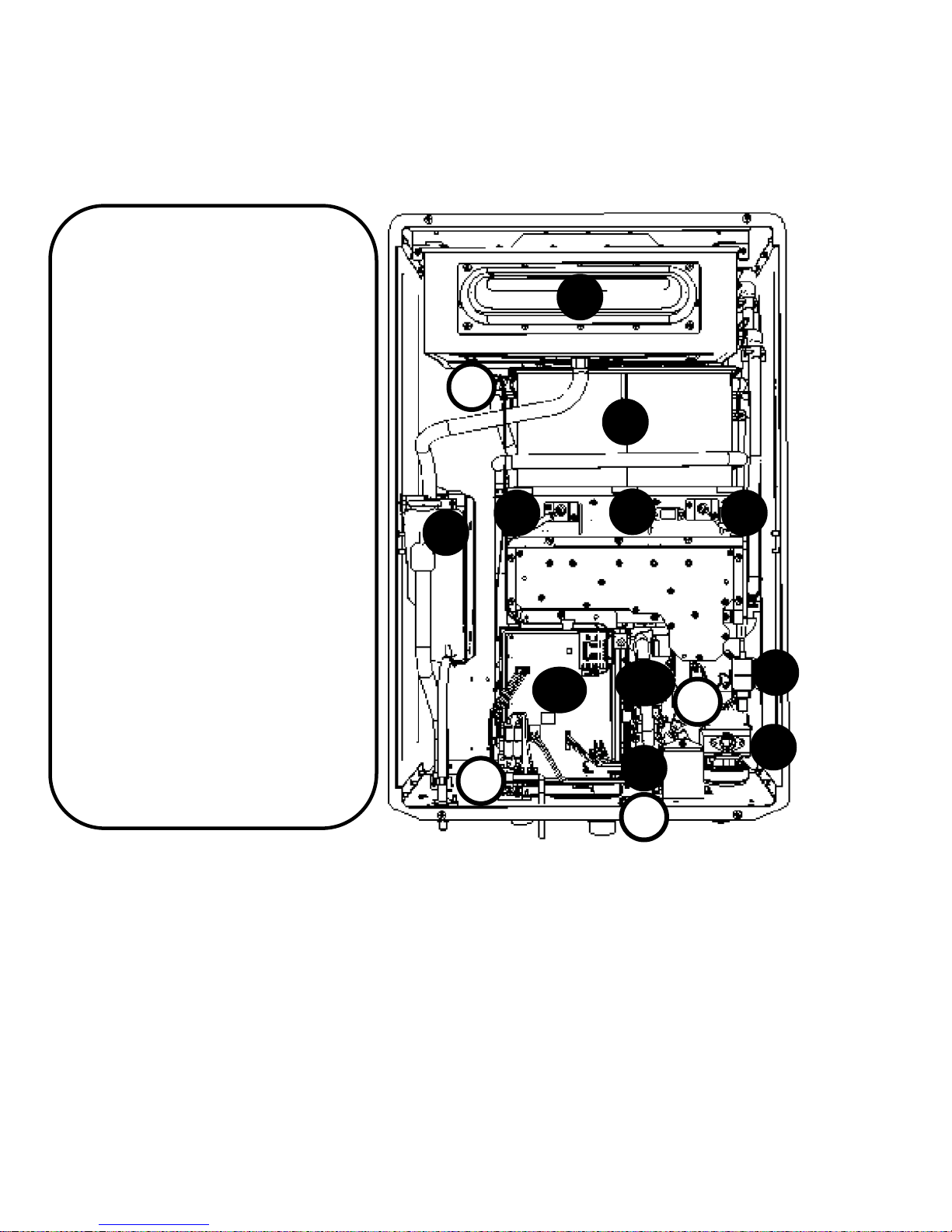
COMPONENTS
1. Condensing ONLY: Secondary
Stainless Steel Heat Exchanger
2. Condensing ONLY: Neutralizer
3. Primary Heat Exchanger
4. Flame Rod(s)
1
5. Sight Glass
6. Igniter Rod
7. Igniter Coil
8. Gas Control Valve
9. Water Control Valve
10. Water Bypass Valve
11. Control Board
12. Blower Motor (Behind Control Board)
A. Heat Exchanger Thermistor
B. Outlet Thermistor
C. Inlet Thermistor
D. Ambient Thermistor
2
A
B
4
11
3
5
10
9
C
6
7
D
8
Page 16
16 | Page SVC 820 Tankless Gas Trouble Shooting Manual
16
Maintenance Mode Panel Di spl ay
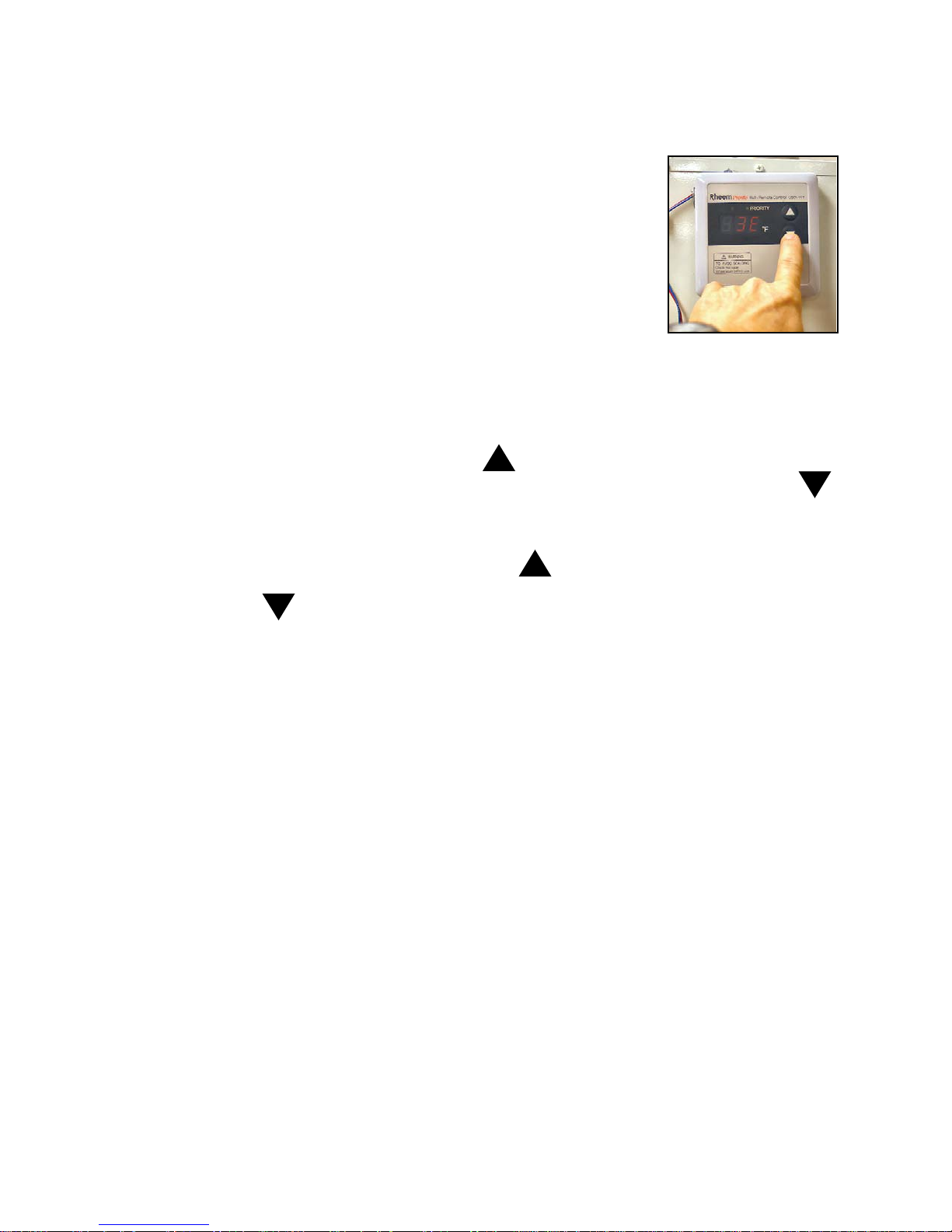
The Rheem Tankless has a Maintenance Mode chart on the Remote Control.
To access the Maintenance Mode, turn the unit OFF at Remote Control. Then
hold down the UP and DOWN arrow keys at the same time for 5 seconds.
You will hear an audible beep and see the display go to 1E. By pressing the
UP and DOWN arrow keys on the remote thermostat, you can access a
variety of information about the water heater. To activate the unit while
displaying the maintenance panel: push the power button once, open a hot
water fixture, and the green LED will illuminate. This will allow you to access
a variety of real time information while the unit is in operation.
Shortcut: Lift dip switch #1 to the up position to go immediately into maintenance mode. This can be
done while the water heater is in operation.
While in Maintenance Mode you want to push the up arrow key to select the table you wish to view.
The table is designated by a letter and is always displayed as the second digit. Then push the down
arrow key to display the number item in the table you selected. You can select as many as 8 readings
for each table.
To perform diagnostics in this service manual, press the up arrow until you get to table
Now using your down arrow you can change the number in front of
diagnostic readings, the selected table will flash first and then the diagnostic reading. You will see the
following as you navigate the
0Y = Flame Rod Status
1Y = Water Flow in gallons per minute
2Y = Ambient air temperature
3Y = Water inlet temperature
4Y = Heat exchanger temperature
5Y = Hot water outlet temperature
6Y = Fan speed (x 100 rpm)
7Y = Power for modulating gas valve
8Y = Null (no reading)
Y table:
Y. As you move through the
1Y.
9Y = Null (no reading)
*FULL MAINTENANCE DISPLAY CHART AVAILABLE ON NEXT PAGE*
Page 17
SVC 820-Tankless Gas Trouble Shooting Manual Page | 17
17
Fault Codes of the most recent 8 f aults
Flame Rod
GPM Flow Rate
Hot Water
Fan Speed x 100
Power for
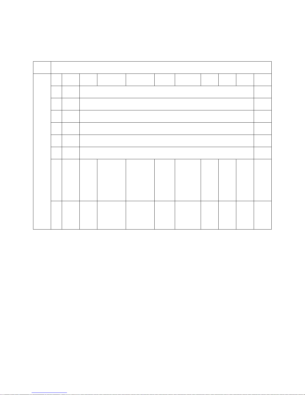
MAINTENANCE INFORMATION TABLE
First Digit – Use DOWN arrow key on Remote Control
0* 1* 2* 3* 4* 5* 6* 7* 8* 9*
*E Null
*F Null Sequence Number of the most recent 8 faults Null
*C Total combustion times until recent error fault (** x 10000times) Null
*D Total combustion times until recent error fault (** x 100 times) Null
*H Total combustion period until recent error fault (** x 1000 hours) Null
*J Total combustion period until recent error fault (** x 10 hours) Null
*Y
Status
*A
Second Digit – Use UP arrow key on Remote Control
Null
Control
(*.* GPM)
Line Fan
Ambient Air
Temperature
Detective
Value
Cold Water Inlet
Temperature
Fan Motor
Current
Heat Exchanger
Temperature
Null
Outlet
Temperature
Null
RPM
P.G.F.R. valve
Null
Null
Null
Null
Null
Null
Sequence
Number
Page 18
18 | Page SVC 820 Tankless Gas Trouble Shooting Manual
18
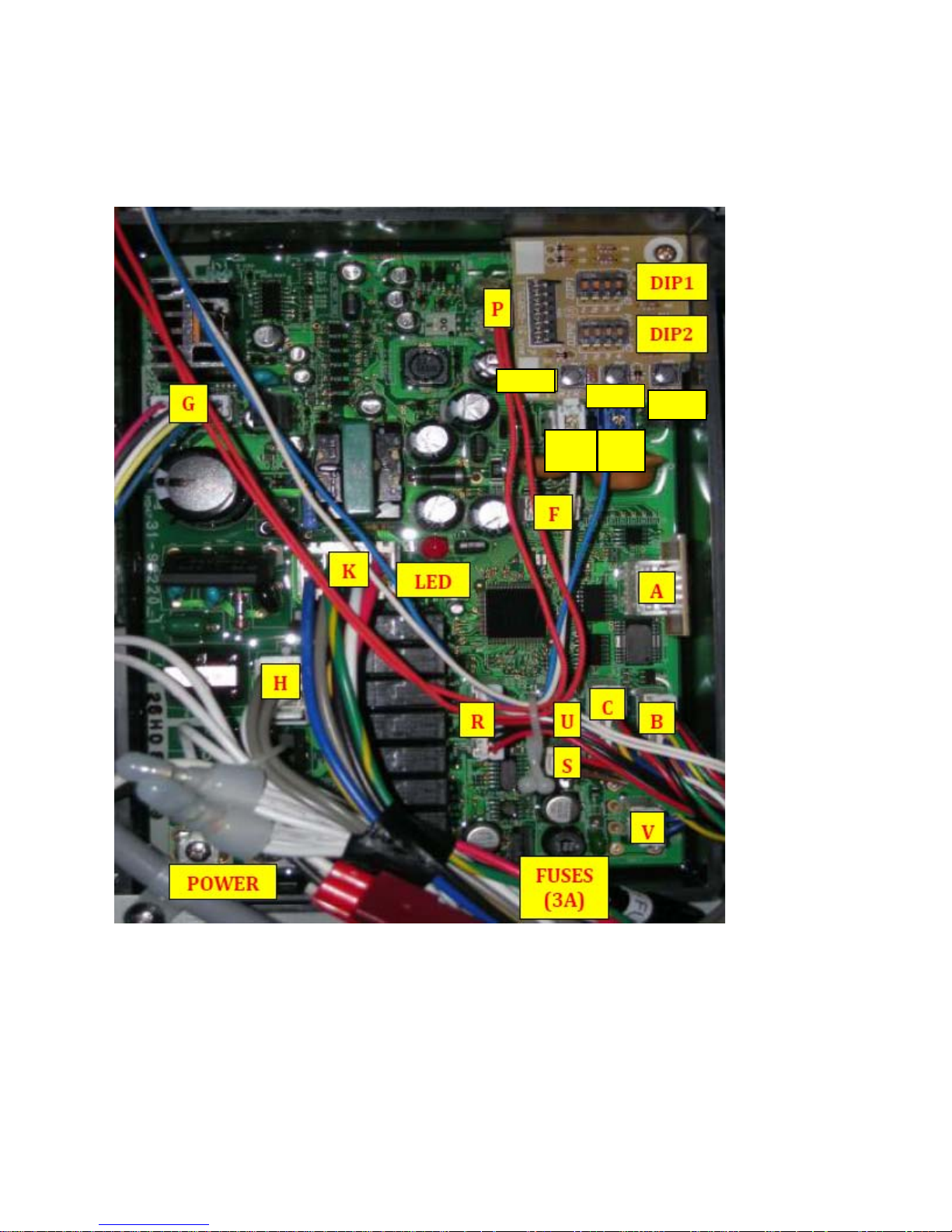
CONTROL BOARD – Color Picture
• Each letter indicates the connector identifier
M T
ADJ
Page 19
SVC 820-Tankless Gas Trouble Shooting Manual Page | 19
19
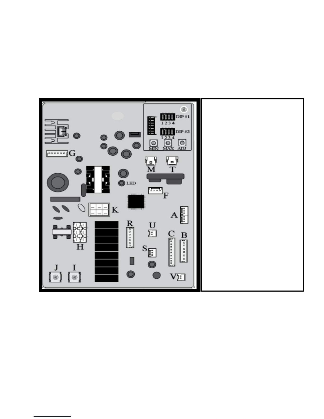
CONTROL BOARD
DIP #1 – Adjust max temperature; EZ Link cable
DIP #2 – Adjust for altitude differential
MIN & MAX (SW1 & SW2) – Adjust water
temperature setting; gas pressure; etc.
ADJ (SW3) – Adjust gas pressure etc.
M – Flame Rod for all models (detects flame)
T – Flame Rod for indoor models only (monitors
combustion efficiency)
F – Communication port (manifold installations)
A – Fuel type and temperature Program Chip
U – Over Heat Limiter (OHL)
R – Thermistors (Ambient, Inlet, Outlet, Heat
Exchanger) & Modulating Gas Valve (PFGR)
S – Water Flow Sensor
C – Water Control Valve
B – Water Bypass Valve
V – Remote Control (Main Bath)
G – Blower Motor
K – Gas Control Valve
H – Igniter Rod
Page 20

20 | Page SVC 820 Tankless Gas Trouble Shooting Manual
20
NOTES:
______________________________________________
______________________________________________
______________________________________________
______________________________________________
______________________________________________
______________________________________________
______________________________________________
______________________________________________
______________________________________________
______________________________________________
______________________________________________
______________________________________________
______________________________________________
______________________________________________
______________________________________________
______________________________________________
______________________________________________
______________________________________________
______________________________________________
______________________________________________
Page 21

SVC 820-Tankless Gas Trouble Shooting Manual Page | 21
21
RESET PROCEDURE:
1. Turn unit OFF. Remove Front Cover. Locate the Dip Switches on
the Control Board.
2. Make sure all the Dip Switches are OFF (down position).
3. Locate the #2 Dip Switch and turn it ON (up position) then
immediately turn it off.
4. Within 5 seconds, press and hold the MIN and MAX button for at
least 2 seconds.
5. The Remote Control will flash briefly.
6. You can operate unit.
CLEARING FAULT HISTORY PROCEDURE:
1. Turn unit OFF. Remove Front Cover. Locate the Dip Switches on
the Control Board.
2. Make sure all the Dip Switches are OFF (down position).
3. Locate the #1 Dip Switch and turn it ON (up position) then
immediately turn it off.
4. Within 5 seconds, press and hold the MIN and MAX button for at
least 2 seconds.
5. The Remote Control will flash briefly. This indicated the fault
history has been cleared.
6. You can verify clearing history by entering Maintenance Mode
and check the code at location 1E. Should read NULL.
Page 22
22 | Page SVC 820 Tankless Gas Trouble Shooting Manual
22
No Error Code & No Hot Water
(Remote Control Displays Hot Water Temperature Setting)
Explanation: No hot water is delivered when water is flowing through unit and Remote Control displays the hot water
temperature setting.
Possible Causes:
• Water Flow
• DIP 1 Setting On Main Control Board (PCB)
• Water flow sensor
Water Flow:
1. Turn OFF water supply to unit. Turn Remote Control OFF; unplug power cord at wall outlet. Wait 10 seconds; plug
power cord back into outlet; wait 20 seconds; turn the Remote Control ON. Turn water supply ON; check the nearest
hot water fixture for hot water. If you have hot water, then the unit needed to be reset.
2. Water flow might be too low. Open multiple hot water fixtures. If unit fires then there is not enough water flow to
engage the unit at a particular fixture. Check your fixture aerator screen(s) for debris. Clean if necessary.
3. Your water lines might be crossed. Make sure your hot and cold water supply lines are connected to the appropriate
hot and cold water assembly connections on the unit.
4. Your water flow may be restricted by a debris in Water Filter. Remove the water filter and inspect. Clean if
necessary.
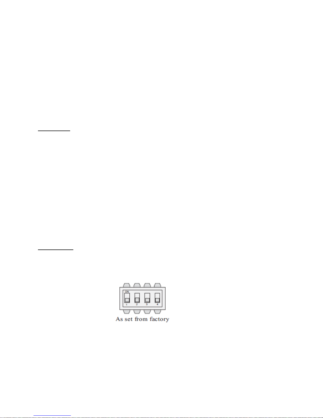
Dip 1 Setting:
All Dip 1 switches must be in the ‘OFF’ position.
Manifold Units ONLY: Go to Error Code 03 to verify proper DIP 1 setting
DIP #1
Page 23

SVC 820-Tankless Gas Trouble Shooting Manual Page | 23
23
P1 - Warning C ode
Explanation: No hot water is delivered when water is flowing through unit and Remote Control displays P1. When water flow
does not reach a minimum 0.4 GPM rate @ 35
Possible Causes:
• Not Enough Water Flow
Water Flow:
Turn the water supply to the unit off. Turn the remote thermostat off, wait 10 seconds and turn the remote thermostat on.
Turn the water supply to the unit on and check the nearest hot water fixture for hot water. If you have hot water, then the unit
needed to be reset.
Your water lines might be crossed. Make sure your hot and cold water supply lines are connected to the appropriate hot and
cold water connections on the unit.
Water flow might be too low. Open multiple hot water fixtures. If unit fires then there is not enough water flow to engage the
unit at a particular fixture. Check your fixture aerator screen(s) for debris. Clean if necessary.
o
T, for five seconds, P1 warning code is displayed.
Your water flow may be restricted by a dirty In-Line Water Filter. Remove the water filter and inspect. Clean if necessary.
Page 24
24 | Page SVC 820 Tankless Gas Trouble Shooting Manual
24
1L - Warning C ode
Explanation: The Control Board has detected possible lime build-up inside the heat exchanger. To prevent permanent damage
to the unit, the unit must be drained and flushed. Flushing procedures may need to be repeated for excessive lime and scale
build-up. To reset 1L Code, hold down the MIN and MAX buttons at the same time for 10 seconds.
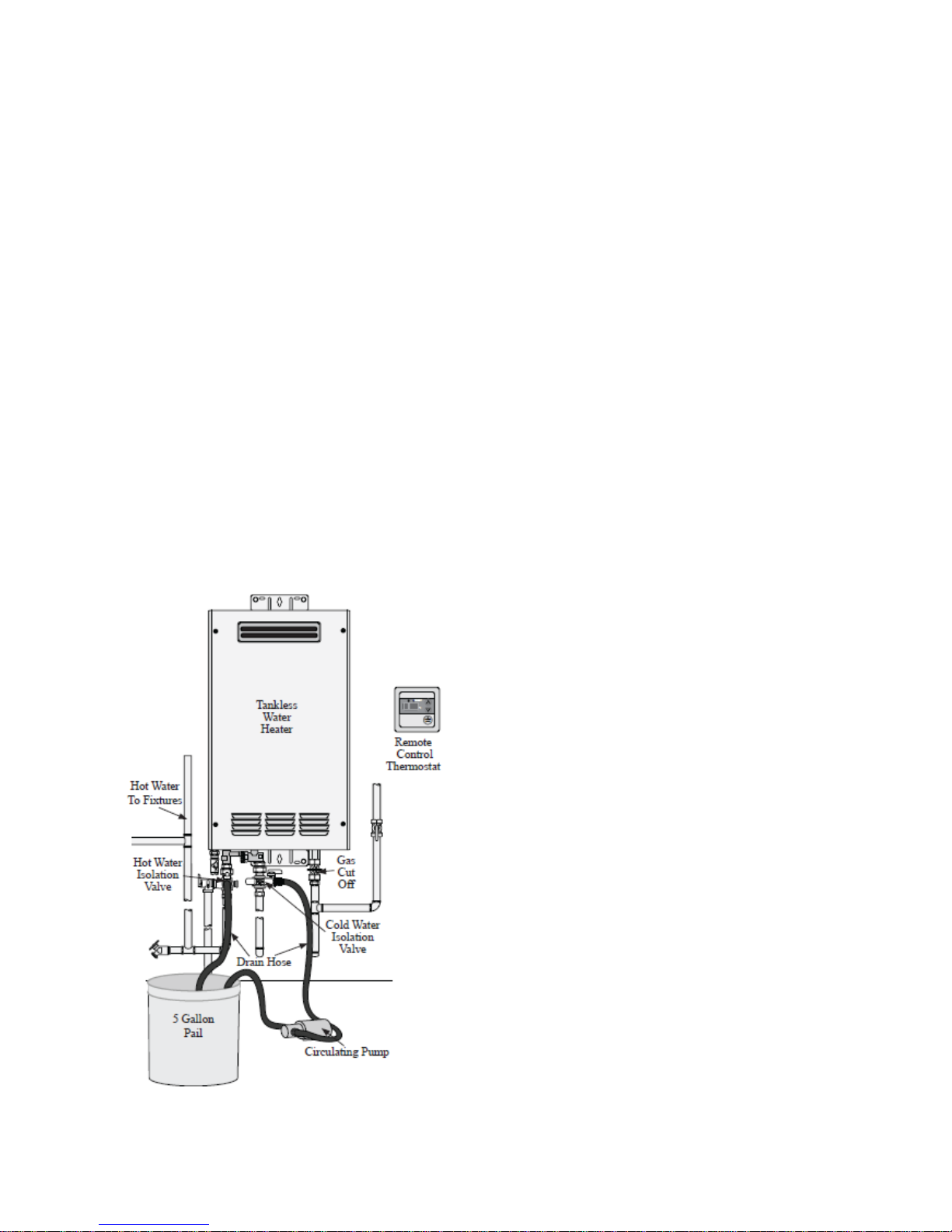
Lime and scale flushing procedure for tankless water heaters:
In areas with hard water conditions the tankless water
heater can develop lime and scale deposits in the heat
exchanger. These depo sits can restrict the water flow and
degrade the performance of your water heater. These
instructions are to provide a safe and effective means to
remove lime and scale build up in the heat exchanger of
your tankless water heater. If you are not co mfortable with
this procedure, then seek the assistance of a plumbing
professional.
Flushing Procedure with Isolation Valves: If your
tankless water heater is not installed with isolation valves,
it is recommended that you seek the assistance of a
plumbing professional.
1. Turn off the electricity and gas, to the tankless
water heater. Do not perform this procedure with
power or gas turned on; damage to the water
heater can occur.
2. Shut off the main water supply valve to the
tankless water heater. Consult the instructions
provided by the isolation valve manufacturer for
specifics in using their valve assemblies.
3. Attach a small garden hose on each drain valve.
Connect the cold water hose to the output of a
small circulation pump. A pond pump or similar
model can be used for this application.
4. Pour approximately five gallons of virgin food
grade white vinegar into a pail.
5. Place the inlet hose of the pump and the drain
hose from the hot water heater into the pail.
6. Open the drain valves and turn on the pump.
Allow solution to circulate for approximately 45
minutes to an hour.
7. Turn off the pump and drain the vinegar from
water heater. Close the cold water drain valve.
8. Open the main cold water supply valve and allow
fresh water to flush through the water heater for
at least 5 minutes to remove all traces of vinegar
from the system.
9. Close the cold water main valve and remove
water filter screen located in cold water inlet of
water heater. Clean the screen of any sediment or
dirt and reinstall the filter. See the Use and Care
Manual provided with your tankless water heater
for detailed instructions.
10. Turn on the water shutoff valves, run a hot water
tap to purge any air from the water lines and
check the system for an y leaks.
11. Turn on gas, electricit y, and remote control
thermostat and set the desired temperature.
12. Run hot water from several locations to check the
operation and performance of the wat er heater.
Page 25
SVC 820-Tankless Gas Trouble Shooting Manual Page | 25
25
03 - Error Code
(Only for manifold installations utilizing EZ-Link; MIC-6; or MIC-185)
Explanation: Communication failure between water heaters, remote control, and/or manifold controller.
Diagnostic Checks:
• DIP1 Setting On Main Control Board (PCB)
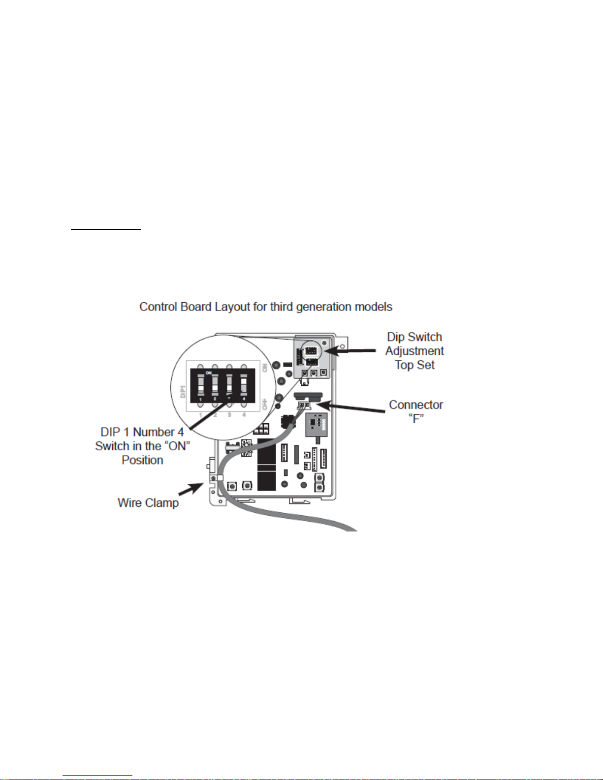
DIP 1 SETTING:
Manifold units only: DIP #1, switch #4 must be in the ‘ON’ position for each unit
Check ALL Molex connections on ALL Control Boards
Page 26

26 | Page SVC 820 Tankless Gas Trouble Shooting Manual
26
05 – Warning Code
Explanation: The Flame Rod has detected improper burner combustion. The unit is NOT able to maintain the proper fuel/air
mixture for proper combustion. This warning code is commonly caused by VENTING and/or GAS SUPPLY. The unit will
continue to operate and attempt to resolve improper combustion, but may eventually shut down with an error code 11, 12, or
13.
Diagnostic Checks:
• GAS SUPPLY & VENTING
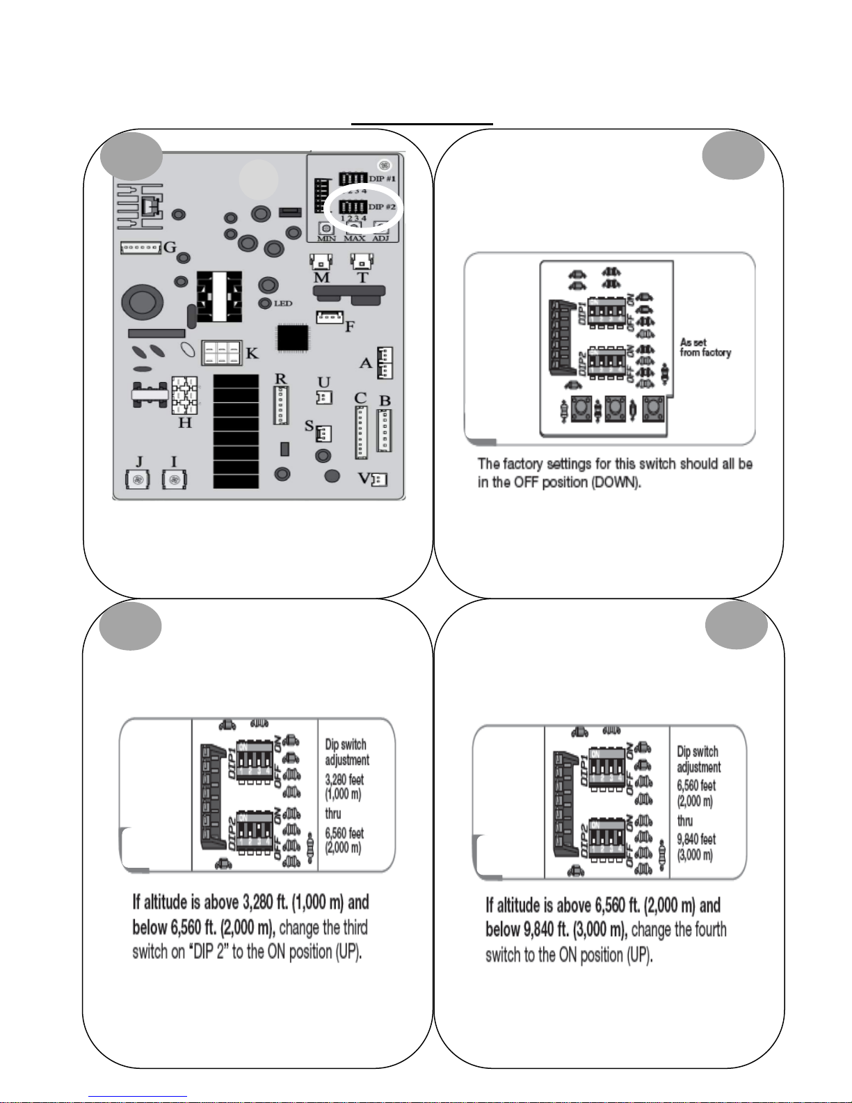
• Dip #2 Setting On Printed Circuit Board (PCB)
Make sure you have sufficient fuel for the unit to operate properly.
1. Gas Type (LP or Natural Gas)
2. Gas Pressure
3. Gas Pipe Size
4. Gas Flex Line Not To Exceed 36” In Length, Has The Proper ID (Inside Diameter), & Correct BTU Rating
5. Gas Regulator
6. Gas Shut Off Valves
7. Air In Gas Line
Visually inspect venting for possible blockage and/or recirculation of exhaust.
1. Approved Venting Materials
2. Approved Vent Terminations
3. Vent Lengths
4. Location Of Vent Termination (Recirculation of exhaust)
5. Blocked Venting
6. Venting Not Sealed Properly
**REFER TO USE & CARE MANUAL**
GAS SUPPLY & VENTING
Page 27
SVC 820-Tankless Gas Trouble Shooting Manual Page | 27
27
op right of PCB.
Switch labeled DIP #2 is the bottom switch.
DIP #2 SETTING:
1
Locate the two DIP switches at t
2
Sea Level to 3,280 Feet
DO NOT ALTER ANY OTHER SWITCHES
3
4
Page 28

28 | Page SVC 820 Tankless Gas Trouble Shooting Manual
28
NOTES:
______________________________________________
______________________________________________
______________________________________________
______________________________________________
______________________________________________
______________________________________________
______________________________________________
______________________________________________
______________________________________________
______________________________________________
______________________________________________
______________________________________________
______________________________________________
______________________________________________
______________________________________________
______________________________________________
______________________________________________
______________________________________________
______________________________________________
______________________________________________
Page 29

SVC 820-Tankless Gas Trouble Shooting Manual Page | 29
29
10 – Warning Code
Explanation: The Blower Motor is not creating enough ventilation. The system passed the pre-purge cycle, but detects vent
blockage during normal operation. The unit will continue to operate but may eventually shut down with Error Code 99.
First check your GAS SUPPLY & VENTING; the most common causes for Error Code 10.
Diagnostic Checks:
• GAS SUPPLY & VENTING
• Blower Motor
GAS SUPPLY & VENTING
Make sure you have sufficient fuel for the unit to operate properly.
1. Gas Type (LP or Natural Gas)
2. Gas Pressure
3. Gas Pipe Size
4. Gas Flex Line Not To Exceed 36” In Length, has the proper ID (Inside Diameter), and correct BTU rating
5. Gas Regulator
6. Gas Shut Off Valves
7. Air In Gas Line
Visually inspect venting for possible blockage and/or recirculation of exhaust.
1. Approved Venting Materials
2. Approved Vent Terminations
3. Vent Lengths
4. Location Of Vent Termination (Recirculation of exhaust)
5. Blocked Venting
6. Venting Not Sealed Properly
**REFER TO USE & CARE MANUAL**
Page 30
30 | Page SVC 820 Tankless Gas Trouble Shooting Manual
30
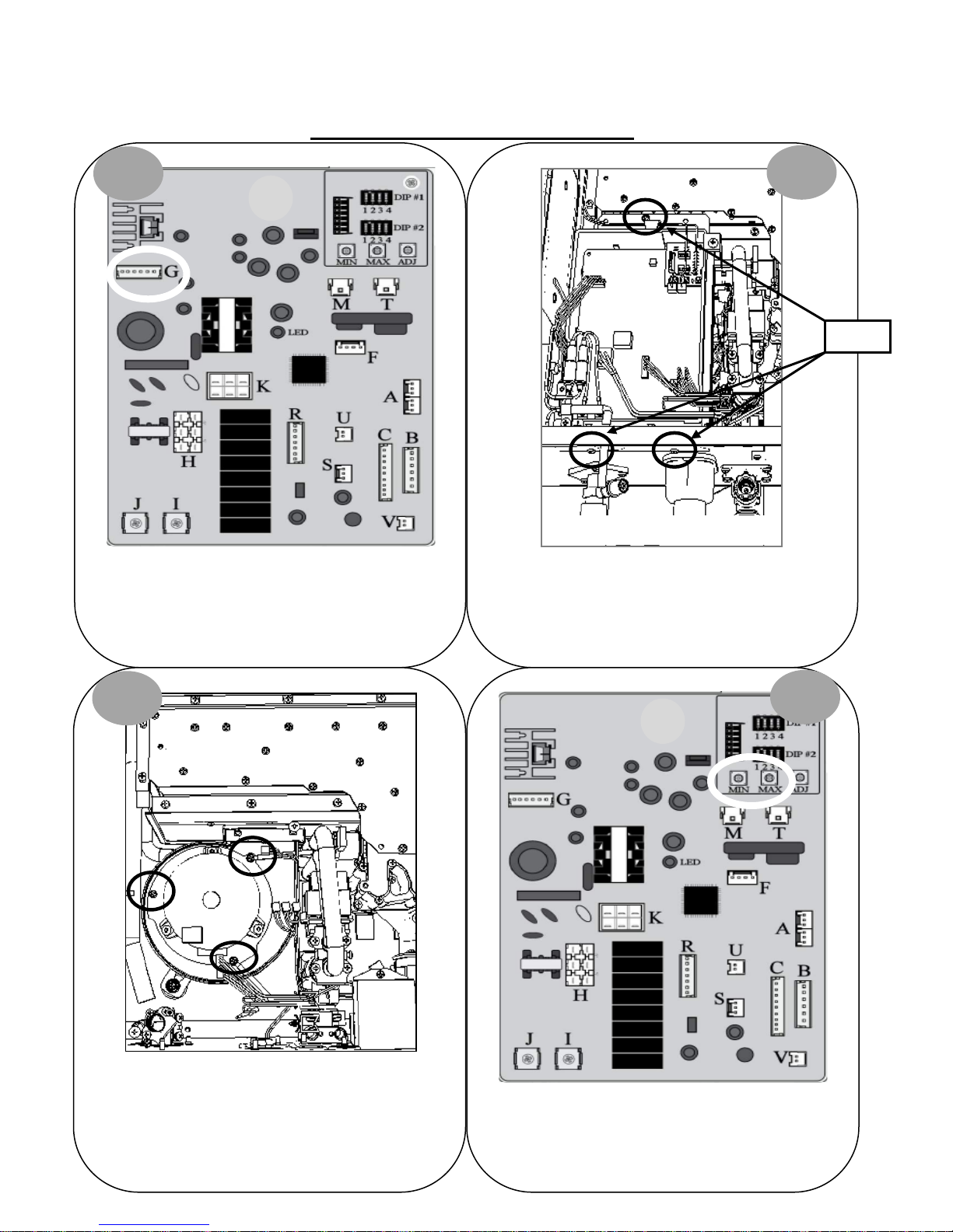
BLOWER MOTOR DIAGNOSTICS:
1
Control Board
2
Screws
Turn power OFF. Remove and reinsert connector “G” on
Control Board. Attempt to operate unit again. IF 10
Warning Code does NOT display, unit had a loose
connection.
3
Blower Motor
Turn power OFF. Remove 3 screws for Control Board
mounting bracket. Remove connectors “M”, “T”, & “G”.
Pull PCB out of way to access Blower Motor.
Bottom of Unit
4
Remove 3 screws holding Blower Motor in place. Clean
Blower Motor and reassemble unit. Attempt to operate
unit again. IF 10 Warning Code does NOT display:
Blower Motor needed to be cleaned.
Locate Min & Max buttons on Control Board.
Continue to diagnostic chart on next page.
Page 31
SVC 820-Tankless Gas Trouble Shooting Manual Page | 31
31
Remove and reinsert connector “G” at
Control Board.
Attempt to operate unit again.
18 DC VOLTS
Control Board.
Attempt to operate unit again.
Control Board and Blower Motor are ‘OK’:
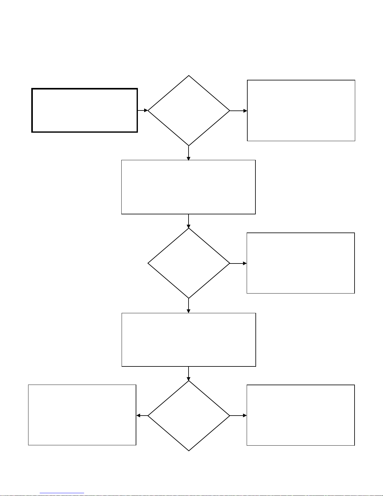
BLOWER MOTOR Diagnostic Chart
Test DC voltage across black and red
wires on connector “G”:
144 – 192 DC VOLTS
Press and hold down “MAX” button on Control Board
to activate the Blower Motor. While Blower Motor is
running, test DC voltage across black and white wires
Is the DC voltage
OK?
YES
on connector “G”:
12 –
NO
IF unit continues to display Error Code 10:
Replace Control Board
Attempt to operate unit again. If unit
continues to display Warning Code 10:
CHECK VENTING & GAS SUPPLY
Is the DC voltage
OK?
YES
Press and hold down “MAX” button on Control Board
to activate the blower motor. While blower is
running, test DC voltage across black and blue wires
on connector “G”:
4 – 10 DC VOLTS
Is the DC voltage
YES NO
OK?
NO
Remove and reinsert connector “G” at
IF unit continues to display Error Code 10:
Replace Control Board
Replace Blower Motor
Page 32

32 | Page SVC 820 Tankless Gas Trouble Shooting Manual
32
NOTES:
______________________________________________
______________________________________________
______________________________________________
______________________________________________
______________________________________________
______________________________________________
______________________________________________
______________________________________________
______________________________________________
______________________________________________
______________________________________________
______________________________________________
______________________________________________
______________________________________________
______________________________________________
______________________________________________
______________________________________________
______________________________________________
______________________________________________
______________________________________________
Page 33

SVC 820-Tankless Gas Trouble Shooting Manual Page | 33
33
11 – Error Code
Explanation: This error code is commonly a result of GAS SUPPLY and/or VENTING. Flame Rod(s) does not detect flame. This
Is caused by the following: Inadequate GAS SUPPLY; Inadequate VENTING; Igniter Rod NOT sparking; Build-up on Flame Rod(s)
caused by inadequate GAS SUPPLY and/or VENTING; Gas Valve.
IMPORTANT: If all water heater components test ‘OK’, you must thoroughly inspect your GAS SUPPLY & VENTING.
First Check: GAS SUPPLY & VENTING
Diagnostic Checks:
• GAS SUPPLY & VENTING
• Igniter Rod
• Flame Rod(s)
• Gas Control Valve
Make sure you have sufficient fuel for the unit to operate properly.
1. Gas Type (LP or Natural Gas)
2. Gas Pressure
3. Gas Pipe Size
4. Gas Flex Line Not To Exceed 36” In Length, has the proper ID (Inside Diameter), and correct BTU rating
5. Gas Regulator
6. Gas Shut Off Valves
7. Air In Gas Line
Visually inspect venting for possible blockage and/or recirculation of exhaust.
1. Approved Venting Materials
2. Approved Vent Terminations
3. Vent Lengths
4. Location Of Vent Termination (Recirculation of exhaust)
5. Blocked Venting
6. Venting Not Sealed Properly
**REFER TO USE & CARE MANUAL**
GAS SUPPLY & VENTING
Page 34
34 | Page SVC 820 Tankless Gas Trouble Shooting Manual
34
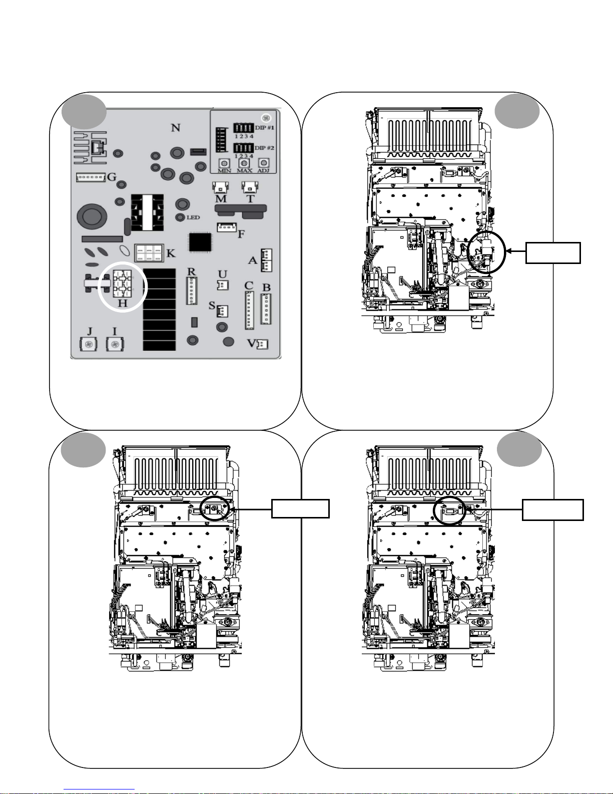
IGNITER ROD DIAGNOSTICS: (spark is NOT visible)
1
Turn power OFF. Remove and reinsert connector “H” on
Control Board.
2
Igniter Coil
Remove and reinsert white Molex connector at Igniter
Coil mounted on right side of unit.
3
Remove and reinsert Igniter Coil cable on Igniter Rod.
Turn power ON.
Igniter Rod
4
Sight Glass
While unit is attempting to ignite, determine IF spark is
visible through sight glass. IF YES, unit had a loose
connection. IF NO, continue to diagnostic chart on next
page.
Page 35
SVC 820-Tankless Gas Trouble Shooting Manual Page | 35
35
Attempt to operate unit again.
across Igniter Coil
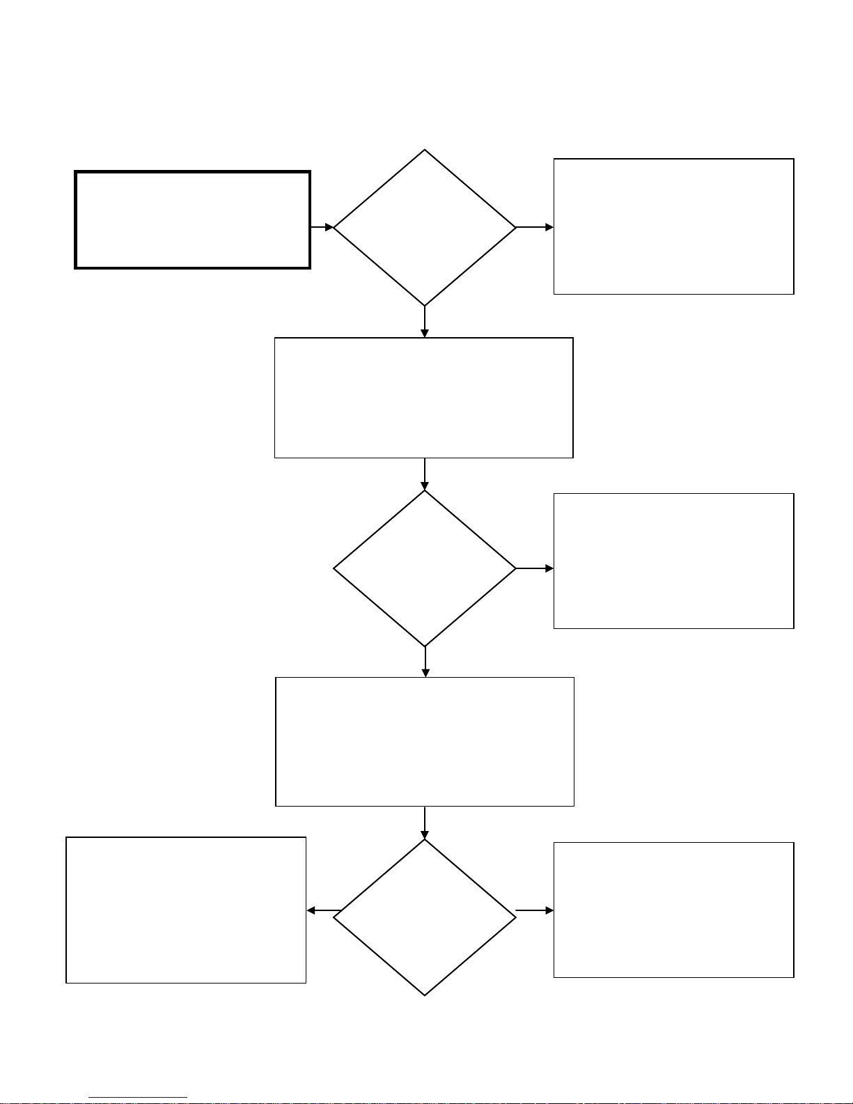
IGNITER ROD Diagnostic Chart
Check AC Volts across 2 grey wires on
connector “H” while unit is attempting to
ignite:
108 – 132 Volts AC
Is the voltage
OK?
YES
Remove Igniter Coil cable from Igniter Rod. While
unit is attempting to ignite, hold end of Igniter Coil
cable 1/8” from end of Igniter Rod.
Make sure you hold Igniter Coil cable on the rubber
insulation while performing this check
NO
IF Igniter Rod does not spark and unit
malfunctions due to Error Code 11:
Replace Control Board
Igniter Rod is ‘OK’
IF unit fails again due to Error Code 11:
IF flame IS visible, diagnose Flame Rods
IF flame is NOT visible, diagnose
Gas Control Valve
Does spark arc
NO
cable and Igniter
Rod?
YES
Remove Igniter Rod and clean.
Reconnect Igniter Coil cable and Igniter Rod.
Attempt to operate unit again.
Is spark visible
YES
through sight
glass?
NO
Replace Igniter Coil
Replace Igniter Rod
Page 36
36 | Page SVC 820 Tankless Gas Trouble Shooting Manual
36
remove any foreign debris. IF foreign debris NOT present:
Remove and reinsert terminals on Flame Rods(s)*.
le.
For Maintenance Mode instructions go to page 16.
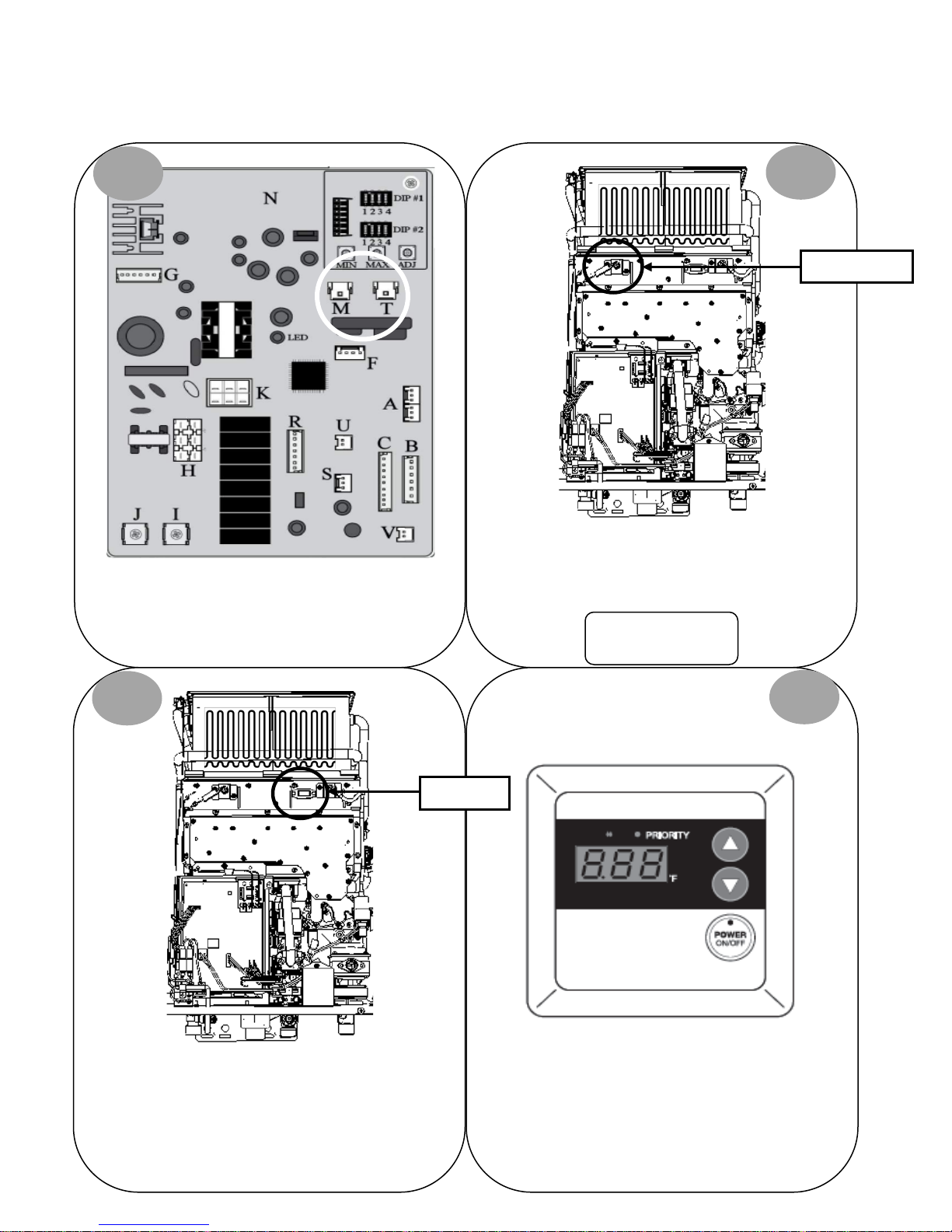
FLAME ROD(S) DIAGNOSTICS: (flame IS visible)
1
Turn power OFF. Remove and reinsert white connector
“M” and blue connector “T” on Control Board.
2
Flame Rod(s)*
Attempt to operate unit again. IF 11 Error Code does NOT
display, unit had a loose connection.
*Indoor Models ONLY:
2 Flame Rods
3
Sight Glass
Locate sight glass. While unit is attempting to ignite,
determine if flame is touching Flame Rod(s). IF NO,
CHECK GAS SUPPLY & VENTING.
On Remote Control; go to Maintenance Mode 0Y tab
Continue to diagnostic chart on next page.
4
Page 37
SVC 820-Tankless Gas Trouble Shooting Manual Page | 37
37
detecting flame?
Indoor Models: 05
Remove and clean Flame Rod(s).
Attempt to operate unit again.
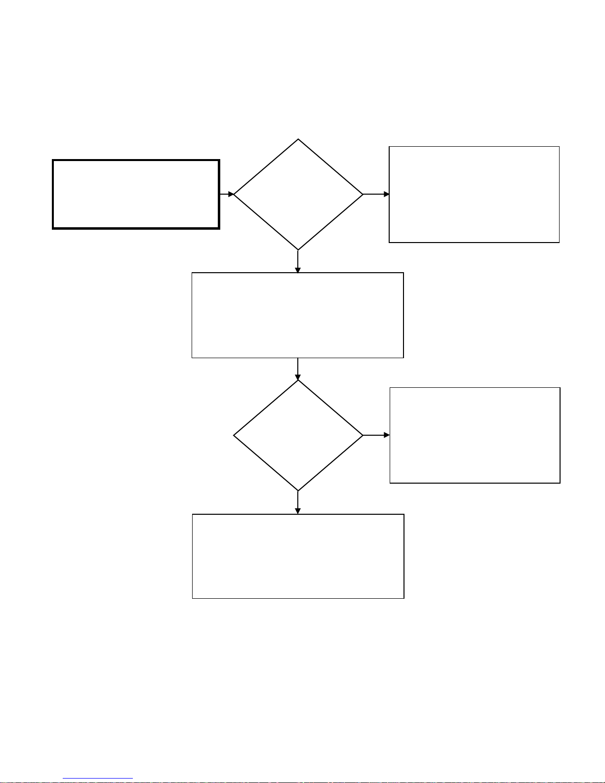
FLAME ROD(s) Diagnostic Chart
Cycle unit ON and check AC Volts at
white “M” & blue “T” connectors:
1 – 100 AC VOLTS
Flame Rod status under table 0Y. IF detecting flame,
Is the AC voltage
OK?
YES
Cycle unit ON; while in Maintenance Mode check
Maintenance Mode will display:
Outdoor Models: 01
Is Flame Rod(s)
NO
NO
Attempt to operate unit again.
IF unit malfunctions due to Error Code 11:
Replace Control Board
IF Flame Rod(s) still does not detect flame:
Replace Flame Rod(s).
Attempt to operate unit again. If the unit
*CHECK: GAS, VENTING, & GROUND*
YES
malfunctions due to an Error Code 11:
Flame Rod(s) are ‘OK’
Page 38
38 | Page SVC 820 Tankless Gas Trouble Shooting Manual
38
connector with black wire on PGFR.
Molex Connectors
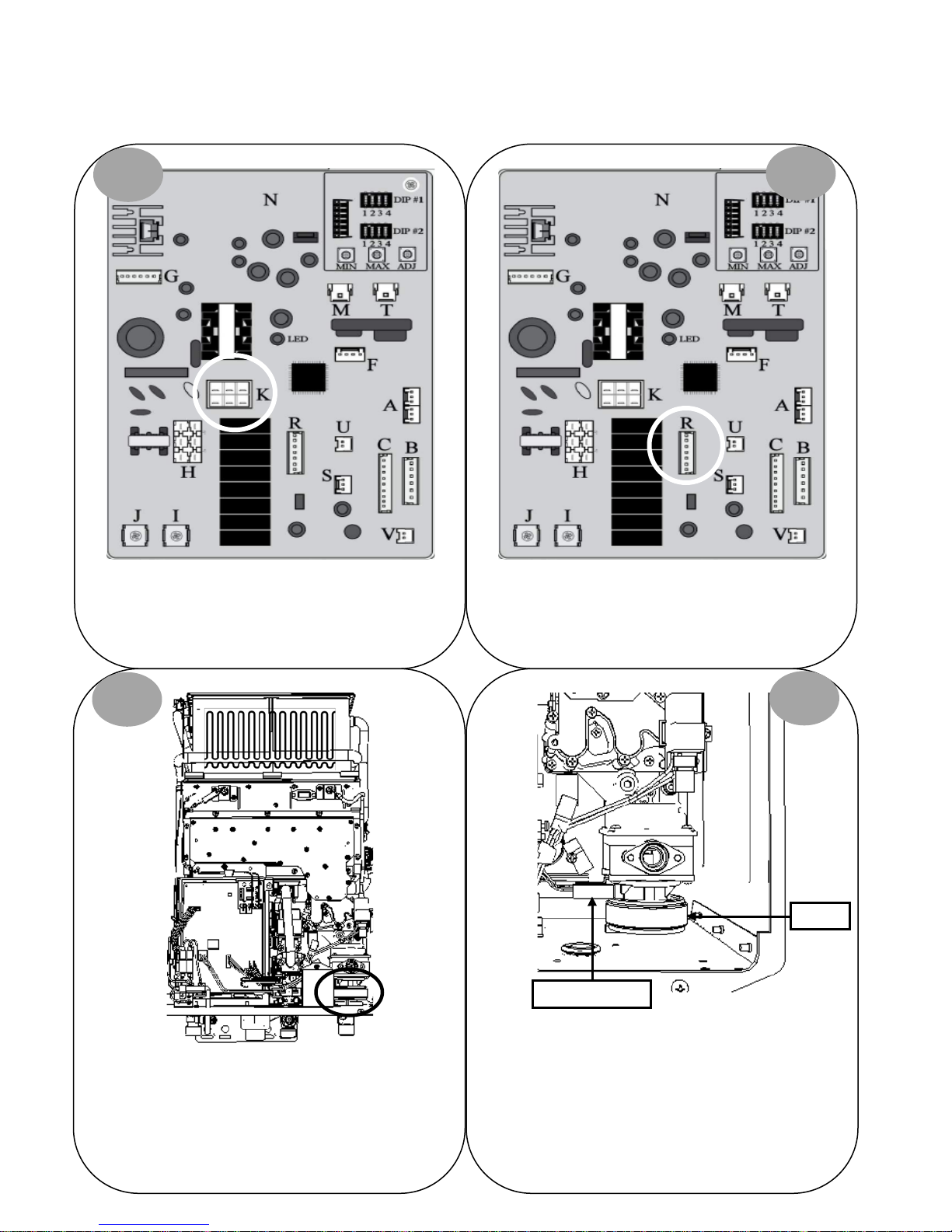
GAS CONTROL VALVE DIAGNOSTICS: (Igniter Rod DOES spark & NO flame)
1
Turn power OFF. Remove and reinsert connector “K” on
Control Board.
2
Remove and reinsert connector “R” on Control Board.
3
Locate PGFR valve on lower right of unit. Remove and
reinsert Molex connector with red wire and Molex
Attempt to operate unit again.
4
PGFR
IF 11 Error Code does NOT display, unit had a loose
IF 11 Error Code IS displayed, continue to diagnostic chart
connection.
on next page.
Page 39
SVC 820-Tankless Gas Trouble Shooting Manual Page | 39
39
Is the DC voltage
Attempt to operate unit again.
Remove and reconnect terminals on PGFR.
Attempt to operate unit again.
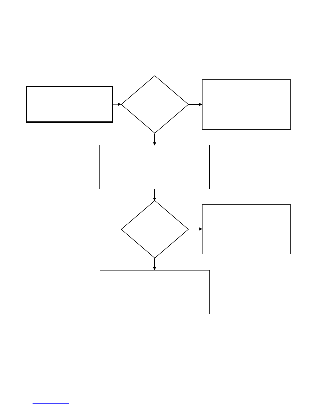
GAS CONTROL VALVE Diagnostic Chart
While unit is attempting to ignite, check
DC voltage across red wire #1 and black
wire #2 on connector “R”:
OK?
NO
IF the unit malfunctions due to an Error
Code 11:
1.5 – 14 DC VOLTS
YES
Turn unit OFF; remove Molex connector “R”.
Measure resistance across red wire #1 and black wire
#2 on Molex connector “R”:
40 – 80 Ohms
Is the resistance
OK?
NO
Replace Control Board
IF unit malfunctions due to Error Code 11:
Replace Gas Control Valve
Continue to next page
YES
PGFR is ‘OK’
Page 40
40 | Page SVC 820 Tankless Gas Trouble Shooting Manual
40
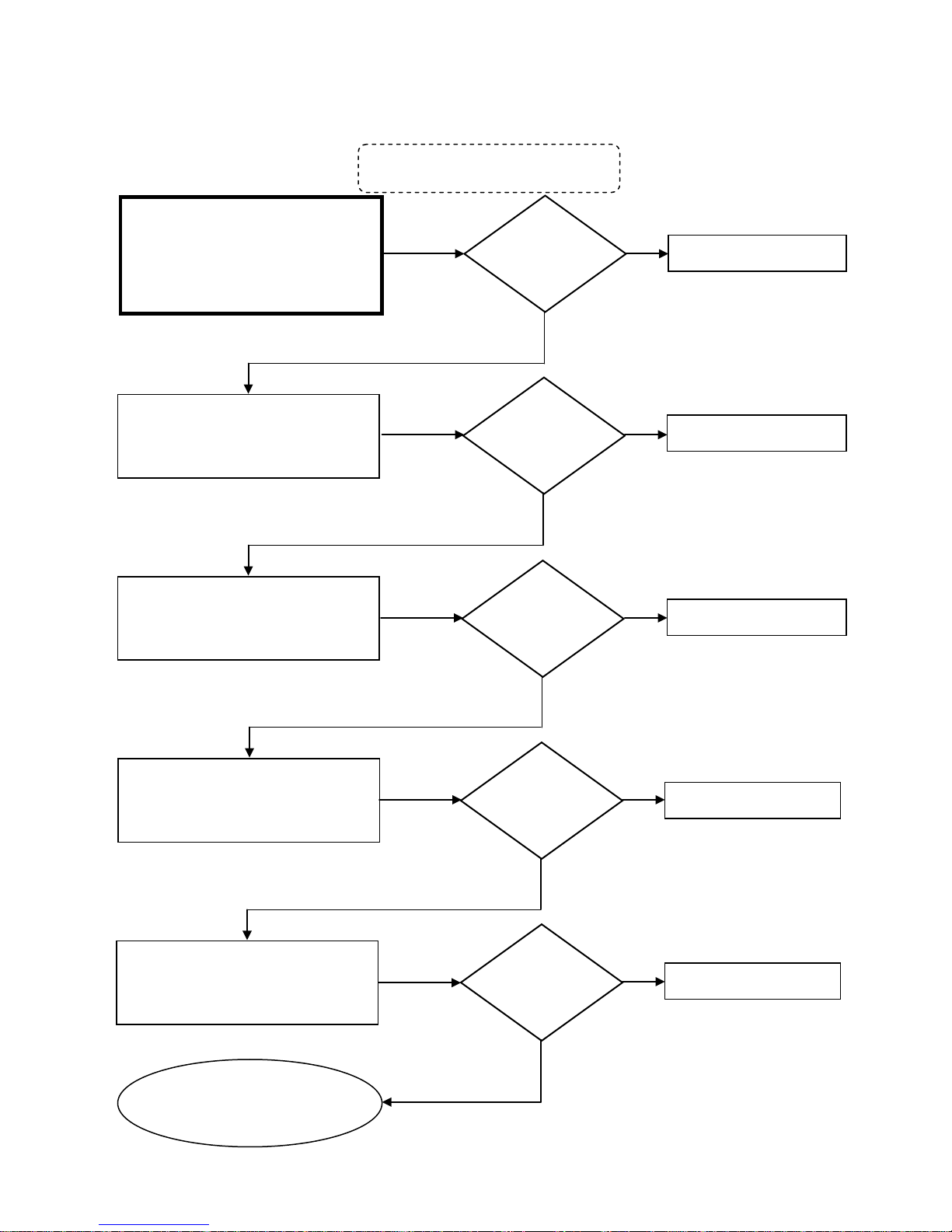
Measure resistance across black wire #6
ire #6
Measure resistance across black wire #6
ure resistance across black wire #6
Turn unit OFF and remove Molex connector
GAS CONTROL VALVE Diagnostic Chart
Measure resistance across black wire #6
and yellow wire #1 on Molex connector
and white wire #2 on connector “K”:
Meas
and grey wire #3 on connector “K”:
“K”:
0.8k – 2.4k Ohms
0.8k – 2.4k Ohms
0.8k – 2.4k Ohms
“K” to measure resistance
Is the
resistance
OK?
YES
Is the
resistance
OK?
YES
Is the
resistance
OK?
NO
NO
NO
Replace Gas Control Valve
Replace Gas Control Valve
Replace Gas Control Valve
and red wire #5 on connector “K”:
0.8k – 2.4k Ohms
Measure resistance across black w
and blue wire #4 on connector “K”:
0.8k – 2.4k Ohms
Gas Control Valve is ‘OK’
Continue to next page
YES
Is the
resistance
OK?
YES
Is the
resistance
OK?
YES
NO
Replace Gas Control Valve
NO
Replace Gas Control Valve
Page 41
SVC 820-Tankless Gas Trouble Shooting Manual Page | 41
41
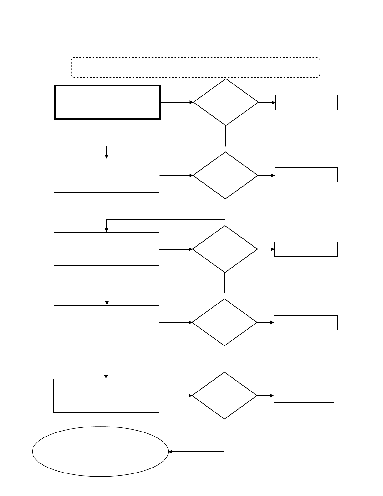
90 – 120 DC Volts
Measure DC voltage across black wire #6
Measure DC voltage across black wire #6
Measure DC voltage across black wire #6
Measure DC voltage across black wire #6
Control Board is ‘OK’
CONTROL BOARD Diagnostic Chart
All voltage checks must be performed while unit is attempting to go to main burner and Molex connector “K” IS
Measure DC voltage across black wire #6
and yellow wire #1 on connector “K”:
and white wire #2 on connector “K”:
90 – 120 DC Volts
and grey wire #3 on connector “K”:
connected to Control Board. Restart unit after each voltage check.
Is the voltage
OK?
YES
Is the voltage
OK?
YES
Is the voltage
OK?
NO
Replace Control Board
NO
Replace Control Board
NO
Replace Control Board
90 – 120 DC Volts
and red wire #5 on connector “K”:
90 – 120 DC Volts
and blue wire #4 on connector “K”:
90 – 120 DC Volts
YES
Is the voltage
OK?
YES
Is the voltage
OK?
YES
NO
Replace Control Board
NO
Replace PCB
IF all components tested ‘OK’:
**CHECK GAS, VENTING, & GROUND**
Page 42

42 | Page SVC 820 Tankless Gas Trouble Shooting Manual
42
NOTES:
______________________________________________
______________________________________________
______________________________________________
______________________________________________
______________________________________________
______________________________________________
______________________________________________
______________________________________________
______________________________________________
______________________________________________
______________________________________________
______________________________________________
______________________________________________
______________________________________________
______________________________________________
______________________________________________
______________________________________________
______________________________________________
______________________________________________
______________________________________________
Page 43

SVC 820-Tankless Gas Trouble Shooting Manual Page | 43
43
12 – Error Code
Explanation: Commonly a result of inadequate GAS
SUPPLY. Unit detected the presence of flame then Flame
Rod lost flame recognition.
Diagnostic Checks:
First Check: *GAS SUPPLY & VENTING*
GAS SUPPLY & VENTING
**REFER TO USE & CARE MANUAL**
Make sure you have sufficient fuel for the unit to operate properly.
1. Gas Type (LP or Natural Gas)
2. Gas Pressure
3. Gas Pipe Size
4. Gas Flex Line Not To Exceed 36” In Length, has the proper ID (Inside Diameter), and correct BTU rating
5. Gas Regulator
6. Gas Shut Off Valves
7. Air In Gas Line
Visually inspect venting for possible blockage and/or recirculation of exhaust.
1. Approved Venting Materials
2. Approved Vent Terminations
3. Vent Lengths
4. Location Of Vent Termination (Recirculation of exhaust)
5. Blocked Venting
6. Venting Not Sealed Properly
• GAS SUPPLY & VENTING
• Flame Rod(s)
• Gas Control Valve
Page 44
44 | Page SVC 820 Tankless Gas Trouble Shooting Manual
44
remove any foreign debris. IF foreign debris NOT present:
Remove and reinsert terminals on Flame Rod(s)*.
On Remote Control; go to Maintenance Mode 0Y table.
For Maintenance Mode instructions go to page 16.
*Indoor Models ONLY:
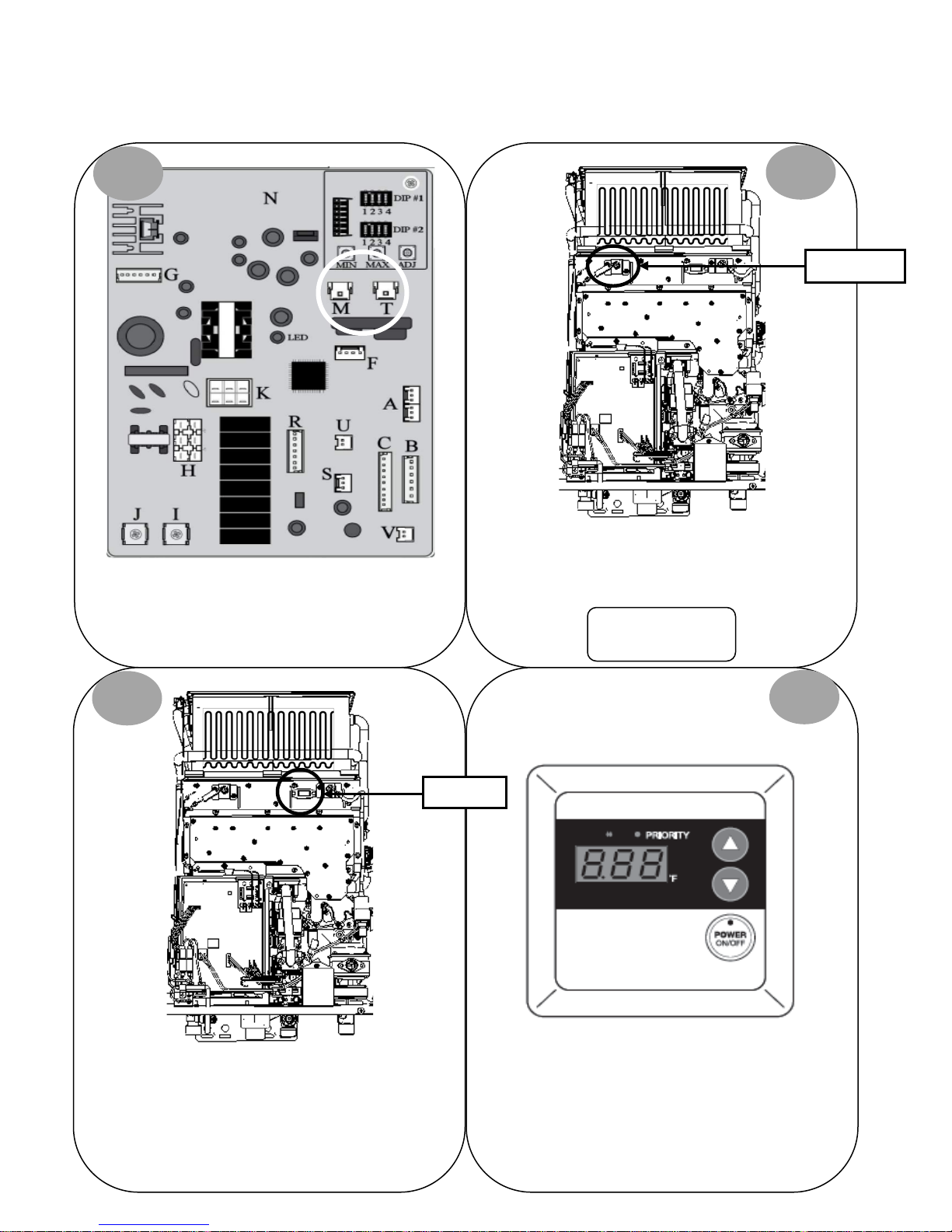
FLAME ROD(S) DIAGNOSTICS: (flame IS visible)
1
Turn power OFF. Remove and reinsert white connector
“M” and blue connector “T” on Control Board.
2
Flame Rod(s)*
Attempt to operate unit again. IF 11 Error Code does NOT
display, unit had a loose connection.
2 Flame Rods
3
Sight Glass
Locate sight glass. While unit is attempting to ignite,
determine if flame is touching Flame Rod(s). IF NO,
CHECK GAS SUPPLY & VENTING.
Continue to diagnostic chart on next page.
4
Page 45
SVC 820-Tankless Gas Trouble Shooting Manual Page | 45
45
detecting flame?
Indoor Models: 05
Attempt to operate unit again.
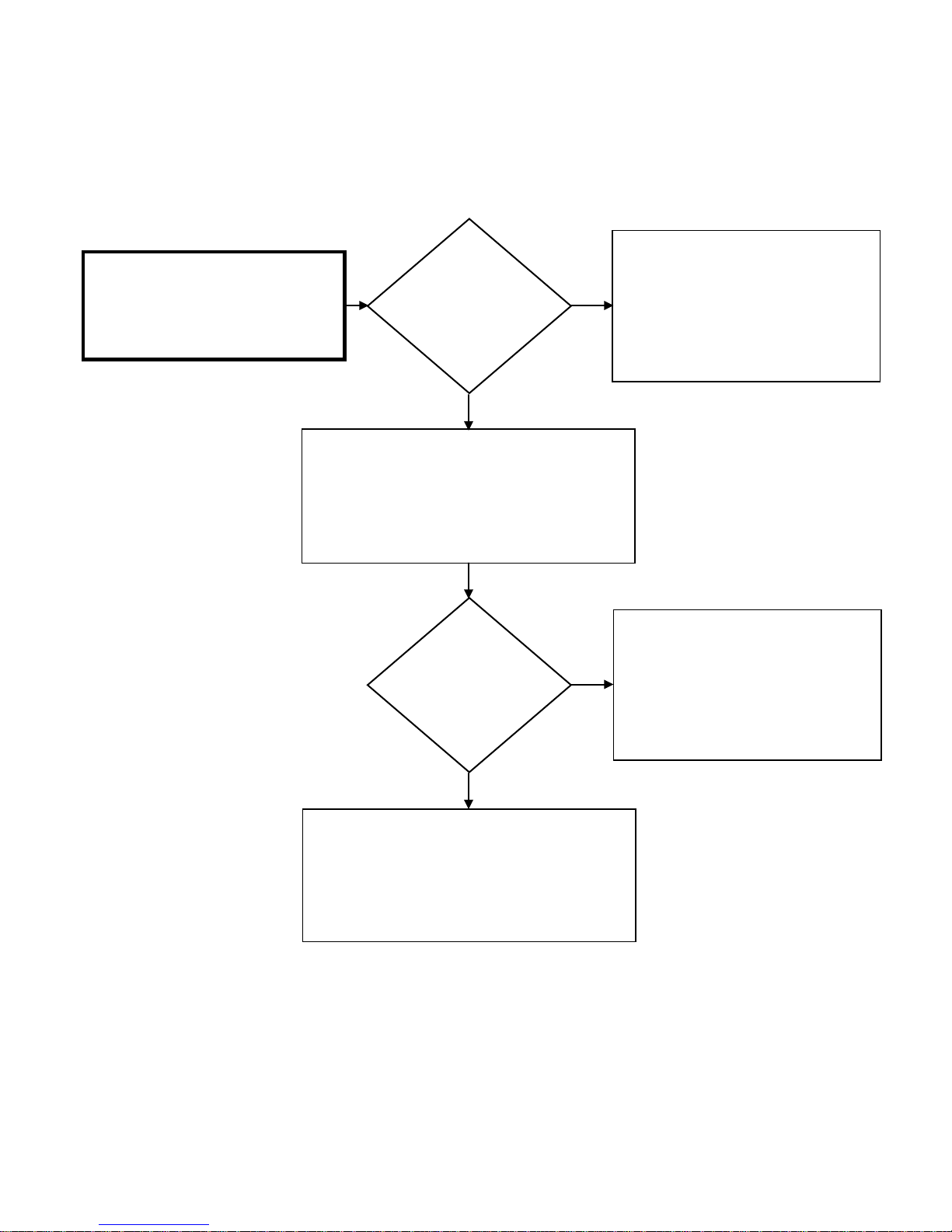
FLAME ROD(s) Diagnostic Chart
Cycle unit ON and check AC Volts at
white “M” & blue “T” connectors:
1 – 100 AC VOLTS
Is the AC voltage
OK?
YES
Cycle unit ON; while in Maintenance Mode check
Flame Rod(s) status under table 0Y. IF detecting
flame, Maintenance Mode will display:
Outdoor Models: 01
Is Flame Rod(s)
NO
NO
Attempt to operate unit again.
IF the unit malfunctions due to an Error
Code 12:
Replace Control Board
Remove and clean Flame Rod(s).
IF Flame Rod(s) still does not detect flame:
Replace Flame Rod(s).
*CHECK: GAS, VENTING, & GROUND*
YES
Attempt to operate unit again. IF the unit
malfunctions due to an Error Code 12:
Flame Rods(s) are ‘OK’
Page 46

46 | Page SVC 820 Tankless Gas Trouble Shooting Manual
46
NOTES:
______________________________________________
______________________________________________
______________________________________________
______________________________________________
______________________________________________
______________________________________________
______________________________________________
______________________________________________
______________________________________________
______________________________________________
______________________________________________
______________________________________________
______________________________________________
______________________________________________
______________________________________________
______________________________________________
______________________________________________
______________________________________________
______________________________________________
______________________________________________
Page 47
SVC 820-Tankless Gas Trouble Shooting Manual Page | 47
47
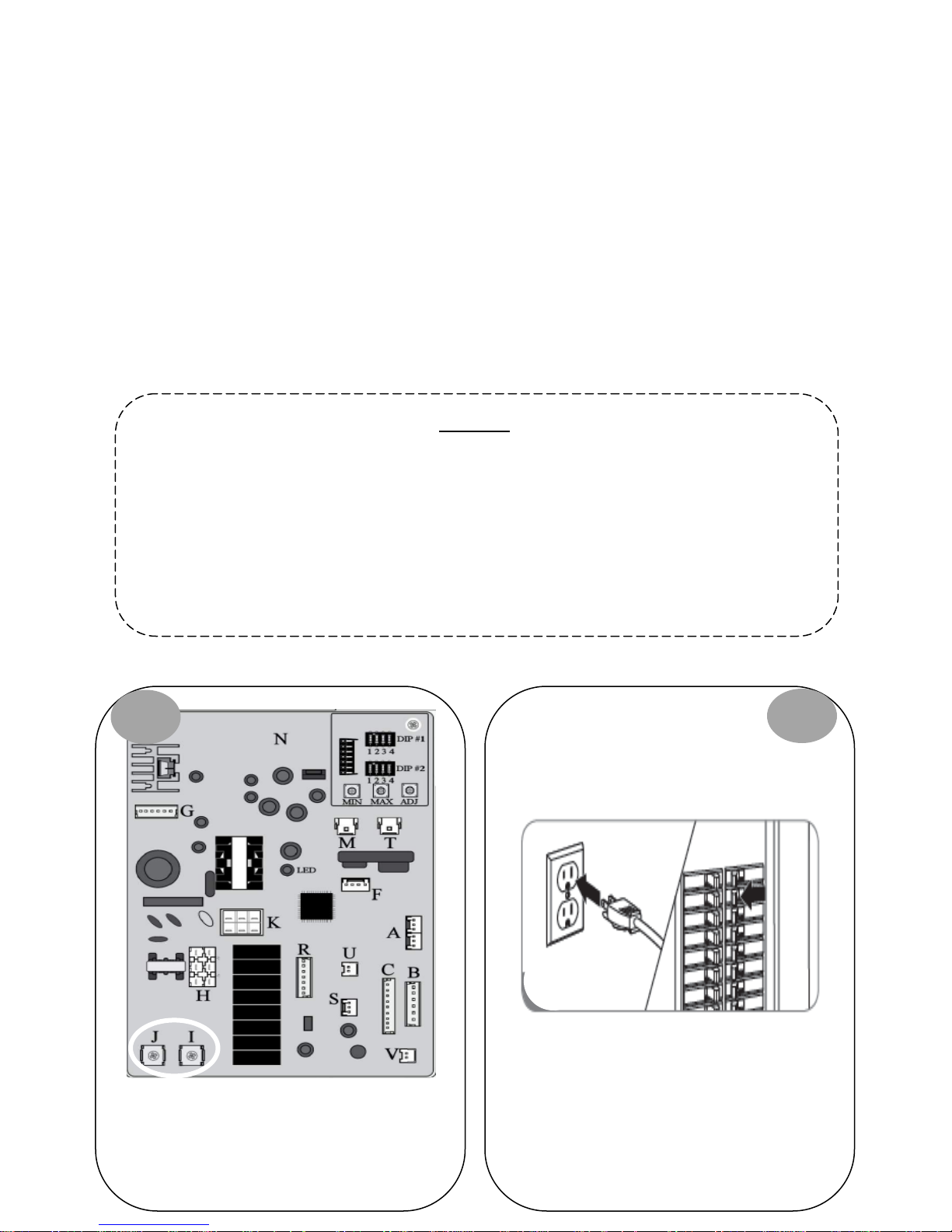
connections on lower left side of PCB.
13 – Error Code
Explanation: Indoor units ONLY. Flame Rod 2 (FL #2) is detecting poor combustion. This is commonly caused by inadequate or
improperly installed VENTING (venting includes fresh air intake and exhaust). Other possible causes: Poor or NO ground
connection; dirty or defective FL #2.
*If unit shuts down 5 times within a 4 hour period due to an error code 13, the unit must be reset by performing reset
procedure on page 21.
First Check: VENTING (Primary cause is blockage of the Fresh Air Intake Vent)
Diagnostic Checks:
• VENTING
• Ground Connection
• Flame Rod FL-2
Visually inspect venting for possible blockage and/or recirculation of exhaust.
1. Approved Venting Materials
2. Approved Vent Terminations
3. Vent Lengths
4. Location Of Vent Termination (Recirculation of exhaust)
5. Blocked Venting
6. Venting Not Sealed Properly
**REFER TO USE & CARE MANUAL**
VENTING:
GROUND CONNECTION DIAGNOSTICS:
1
Locate and visually inspect green ground wire
Ensure the wires are connected properly and not
damaged.
Ensure you have a proper ground at power supply to
unit.
2
Page 48
48 | Page SVC 820 Tankless Gas Trouble Shooting Manual
48
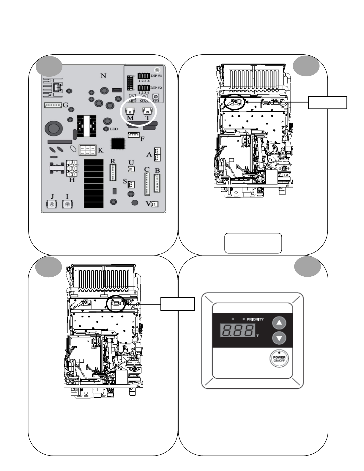
remove any foreign debris. IF foreign debris NOT present:
ame Rod(s)*.
On Remote Control; go to Maintenance Mode 0Y table.
For Maintenance Mode instructions go to page 16.
FLAME ROD(S) DIAGNOSTICS: (flame IS visible)
1
Turn power OFF. Remove and reinsert white connector
“M” and blue connector “T” on Control Board.
2
Flame Rod(s)*
Remove and reinsert terminals on Fl
Attempt to operate unit again. IF 11 Error Code does NOT
display, unit had a loose connection.
*Indoor Models ONLY:
2 Flame Rods
3
Sight Glass
Locate sight glass. While unit is attempting to ignite,
determine if flame is touching Flame Rod(s). IF NO,
CHECK GAS SUPPLY & VENTING.
Continue to diagnostic chart on next page.
4
Page 49
SVC 820-Tankless Gas Trouble Shooting Manual Page | 49
49
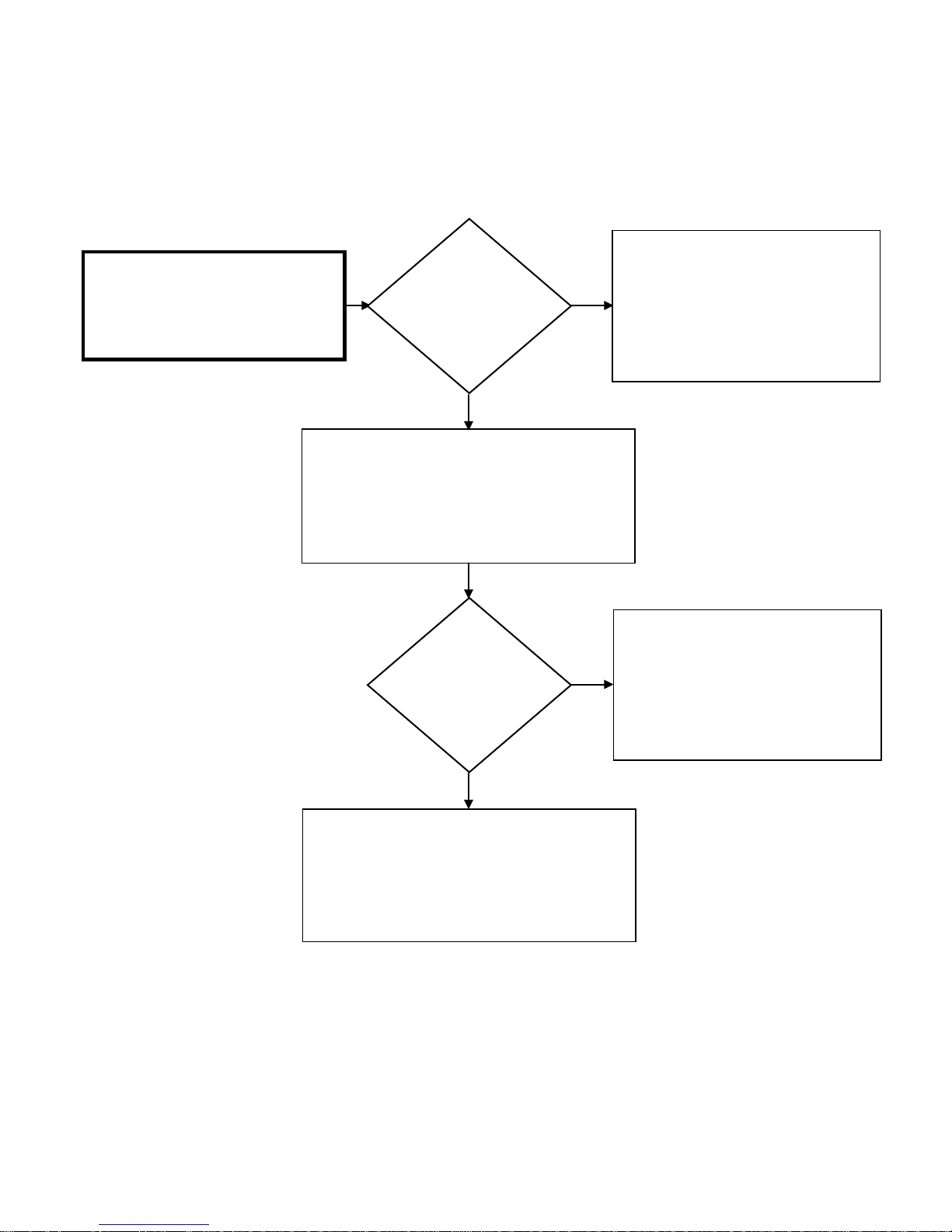
detecting flame?
Indoor Models: 05
Remove and clean Flame Rod(s).
Attempt to operate unit again.
FLAME ROD(s) Diagnostic Chart
Cycle unit ON and check AC Volts at
white “M” & blue “T” connectors:
1 – 100 AC VOLTS
Is the AC voltage
OK?
YES
Cycle unit ON; while in Maintenance Mode check
Flame Rod(s) status under table 0Y. IF detecting
flame, Maintenance Mode will display:
Outdoor Models: 01
Is Flame Rod(s)
NO
NO
Attempt to operate unit again.
IF the unit malfunctions due to an Error
Code 13:
Replace Control Board
IF Flame Rod(s) still does not detect flame:
Replace Flame Rod(s).
Flame Rod(s) are ‘OK’ – Unit operation is normal:
YES
Attempt to operate unit again. If the unit
malfunctions due to an Error Code 13:
CHECK VENTING
Page 50
50 | Page SVC 820 Tankless Gas Trouble Shooting Manual
50
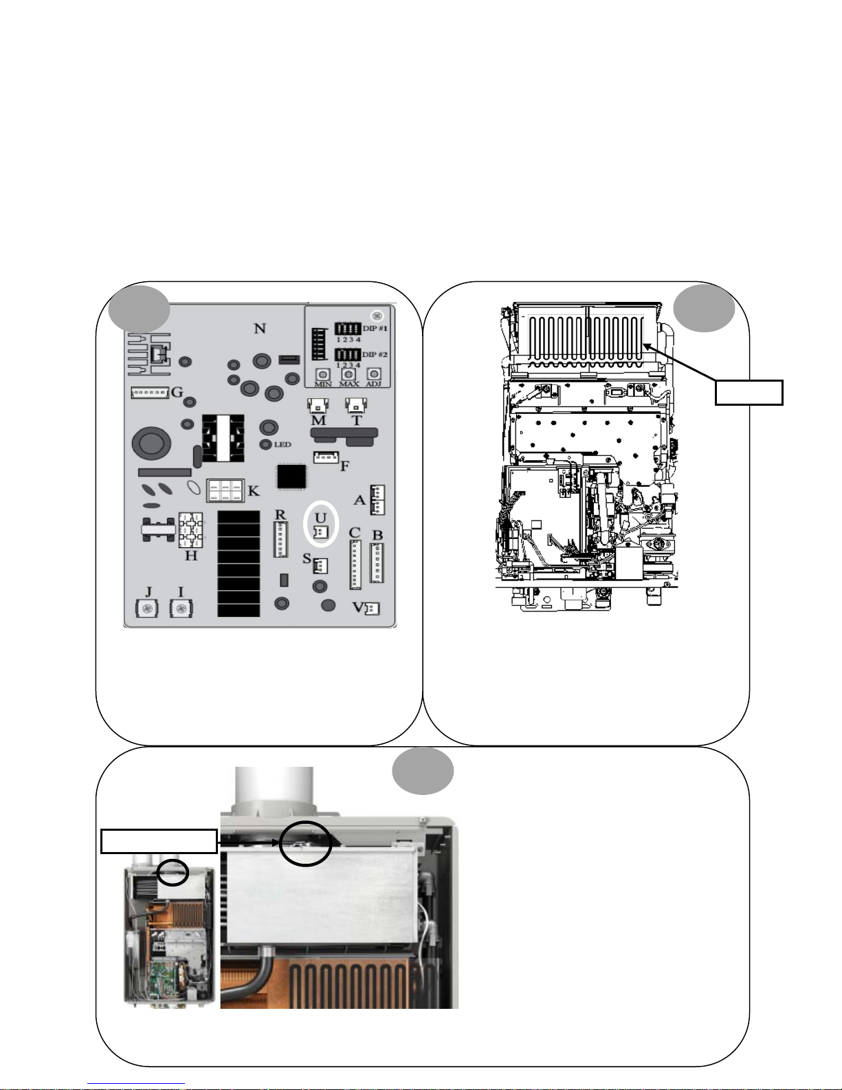
Mid Efficiency ONLY:
High Efficiency ONLY:
a loose connection.
OHL
Over Temp Switch
14 – Error Code
Explanation:
Mid & High Efficiency: Over Heat Limiter (OHL)
malfunction.
High Efficiency ONLY:
Over heat condition in the venting has triggered the Over
Temp Limit Switch
OHL DIAGNOSTICS:
1
Diagnostic Checks:
• Mid & High Efficiency:
OHL
• High Efficiency ONLY:
Over Temp Limit Switch
2
Turn power OFF. Remove and reinsert white
connector “U” on Control Board (white Molex with 2
white wires). Attempt to operate unit again.
IF 14 Error Code does NOT display, unit had a loose
connection. IF 14 Error Code IS displayed, continue to
diagnostic chart on next page.
3
IF 14 Error Code does NOT display, unit had
IF 14 Error Code IS displayed, locate the over
temp switch and continue to diagnostic
chart on next page.
Page 51
SVC 820-Tankless Gas Trouble Shooting Manual Page | 51
51
inadequate VENTING.
14 – Error Code Diagnostic Chart
Turn power OFF and remove Molex
connector “U”. Measure resistance
between both white wires:
Mid Efficiency Unit ONLY:
Replace Unit
Reconnect the Molex; attempt to operate unit again.
50K – 500K Ohms
Is the resistance
to the OHL ‘OK’?
YES
Did the unit shut
down due to
Error Code 14?
NO
NO
The OHL has activated due to excessive
temperatures. This is normally caused by
inadequate/wrong GAS SUPPLY or
Check GAS SUPPLY & VENTING
Unit had a loose connection, operation
appears to be normal.
NO
Is this a High
Efficiency Unit?
YES
High Efficiency ONLY:
Check for continuity across the
Over Temp Switch
Is the continuity
‘OK’?
YES
Replace Control Board
High Efficiency ONLY:
NO
Replace Over Temp Switch
YES
High Efficiency ONLY:
Replace Unit
Page 52

52 | Page SVC 820 Tankless Gas Trouble Shooting Manual
52
NOTES:
______________________________________________
______________________________________________
______________________________________________
______________________________________________
______________________________________________
______________________________________________
______________________________________________
______________________________________________
______________________________________________
______________________________________________
______________________________________________
______________________________________________
______________________________________________
______________________________________________
______________________________________________
______________________________________________
______________________________________________
______________________________________________
______________________________________________
______________________________________________
Page 53

SVC 820-Tankless Gas Trouble Shooting Manual Page | 53
53
15 – Error Code
Explanation: The hot water temperature and/or heat exchanger temperature reached 207 degrees F for more than 15
seconds.
IMPORTANT: Inadequate GAS SUPPLY and/or VENTING will create hot spots in the heat exchanger.
Diagnostic Checks:
• GAS SUPPLY & VENTING
• Sediment Build-Up in Heat Exchanger
• Heat Exchanger Temperature Sensor
Make sure you have sufficient fuel for the unit to operate properly.
1. Gas Type (LP or Natural Gas)
2. Gas Pressure
3. Gas Pipe Size
4. Gas Flex Line Not To Exceed 36” In Length, has the proper ID (Inside Diameter), and correct BTU rating
5. Gas Regulator
6. Gas Shut Off Valves
7. Air In Gas Line
Visually inspect venting for possible blockage and/or recirculation of exhaust.
1. Approved Venting Materials
2. Approved Vent Terminations
3. Vent Lengths
4. Location Of Vent Termination (Recirculation of exhaust)
5. Blocked Venting
6. Venting Not Sealed Properly
**REFER TO USE & CARE MANUAL**
SEDIMENT BUILD-UP DIAGNOSTICS:
Go to Error Code 1L for flushing instructions
HEAT EXCHANGER TEMPERATURE SENSOR DIAGNOSTICS:
Go to Error Code 32 for Heat Exchanger Temperature Sensor diagnostic instructions.
GAS SUPPLY & VENTING
Page 54
54 | Page SVC 820 Tankless Gas Trouble Shooting Manual
54
16 – Error Code
Explanation: Outlet water temperature is too hot. The
water temperature is above the set point on Remote
Control.
Check the Outlet Thermistor FIRST.
Diagnostic Checks:
1. Outlet Thermistor
2. Water Bypass Valve
OUTLET WATER TEMPERATURE SENSOR DIAGNOSTICS:
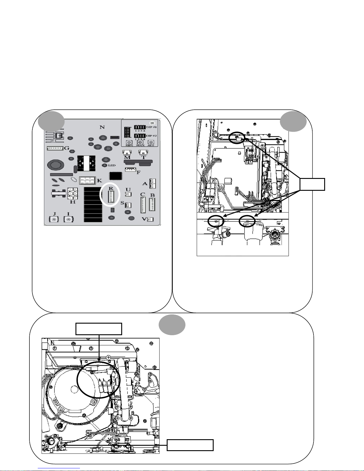
1 2
Control Board
Turn power OFF. Remove connector “R” on Control
Board. Measure resistance between Black #3 & red
#4 wires: 7K – 23K Ohms. IF OK, attempt to operate
unit again. IF 16 Error Code does NOT display, unit
IF resistance tested OK and 16 Error Code IS
displayed, go to Error Code 66 for Water Bypass Valve
diagnostics. IF resistance NOT OK, go to step 2.
had a loose connection.
Turn power OFF. Remove 3 screws for Control Board
mounting bracket. Remove connectors “M”, “T” &
“G”. Pull control board out of way to access BLACK
Molex for Outlet Thermistor located near the Blower
Bottom of Unit
Motor.
Screws
Molex Connectors
3
Separate top and bottom of BLACK
Molex for Outlet Thermistor. Top of
Molex has 2 black wires and 1 red
wire. Bottom of Molex has 2 black
wires. Continue to diagnostic chart
on next page.
Outlet Thermistor
Page 55
SVC 820-Tankless Gas Trouble Shooting Manual Page | 55
55
Clean Outlet Thermistor. Retest
16 – Error Code Diagnostic Chart
Check the resistance across 2 black wires
on bottom Molex:
7k – 23K Ohms
connector “R” and black wires on black Molex located
Is the resistance
to the Outlet
Thermistor OK?
YES
Remove Molex from connector “R” at Control Board.
Check continuity from black #3 wire at Molex
behind Control Board. Check continuity from red #4
wire at Molex connector “R” and red wire on black
Molex located behind Control Board
Is the continuity
across all wires
OK?
NO
NO
Thermistor. IF tests OK, the water heater
appears to be normal, attempt to operate
unit again. IF resistance NOT OK:
Replace Outlet Thermistor
Replace wiring harness for connector “R”
on Control Board
YES
Attempt to operate unit again.
If the unit malfunctions due to an Error Code 16:
Go to Error Code 66 for Water Bypass Valve
diagnostics
Page 56
56 | Page SVC 820 Tankless Gas Trouble Shooting Manual
56
1
loose connection.
24 – Error Code
Explanation: Remote Control buttons were depressed for more than 20 seconds. IF you were manually holding down any
Remote Control buttons for more than 20 seconds, release the buttons and NO Error Code will be displayed. Unit will operate
normally. IF error code 24 is still displayed after releasing Remote Control buttons, continue to Remote Control diagnostics.
Diagnostic Checks:
• Remote Control
REMOTE CONTROL DIAGNOSTICS:
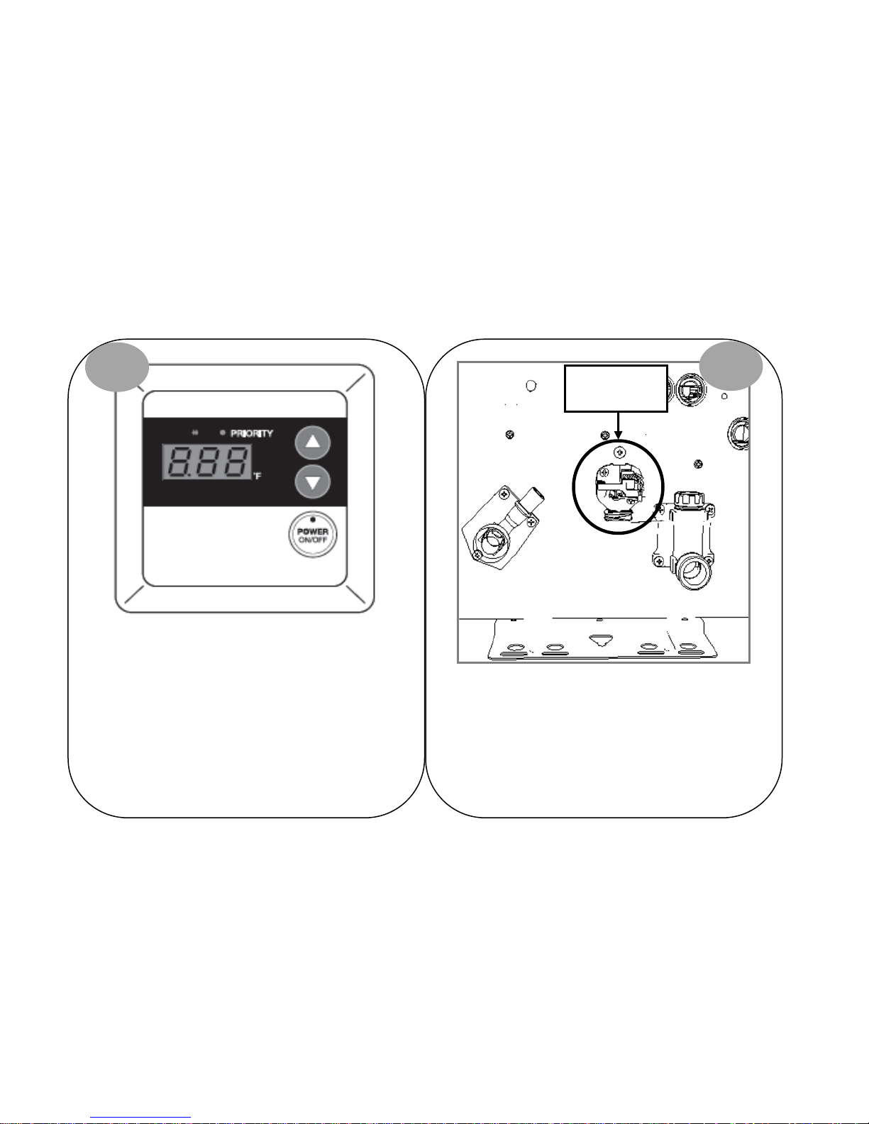
Visually inspect Remote Control wiring for damaged or
loose terminals.
Remote Control
2
Wiring Terminals
Hot Water Outlet
Cold Water Inlet
Turn power OFF. Remove and reconnect Remote Control
wiring terminals at bottom of unit. Attempt to operate
unit again. IF 24 Error Code does NOT display, unit had a
IF 24 Error Code IS displayed, continue to diagnostic chart
on next page.
Page 57
SVC 820-Tankless Gas Trouble Shooting Manual Page | 57
57
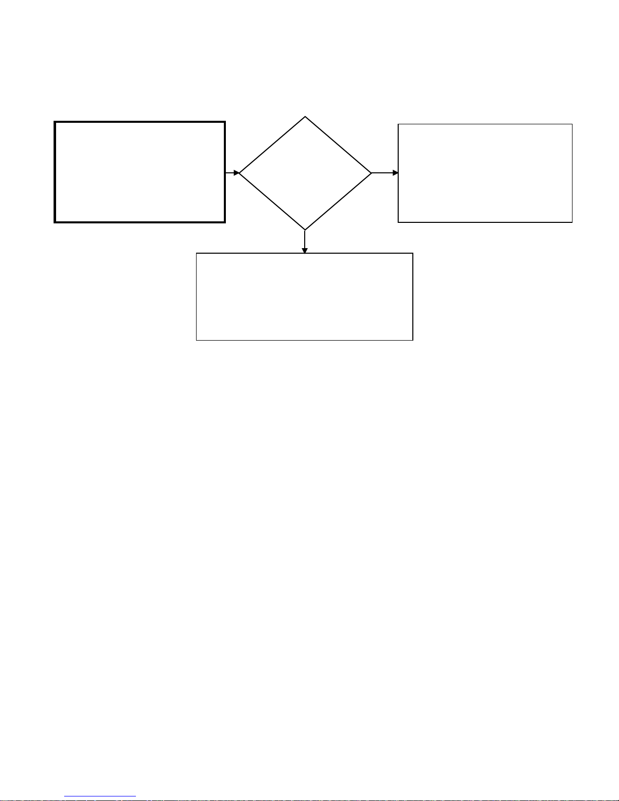
24 – Error Code Diagnostic Chart
Unplug unit and remove Remote Control
wires from wiring terminals on bottom of
unit. Use a new short piece of wire to
connect the Remote Control directly to
the Remote Control Wiring Terminals
located at bottom of unit. Plug unit in
and open a hot water source.
Did the unit
display Error
Code 24?
YES
Replace Remote Control
NO
The wiring is defective.
Replace Remote Control wiring.
Page 58

58 | Page SVC 820 Tankless Gas Trouble Shooting Manual
58
NOTES:
______________________________________________
______________________________________________
______________________________________________
______________________________________________
______________________________________________
______________________________________________
______________________________________________
______________________________________________
______________________________________________
______________________________________________
______________________________________________
______________________________________________
______________________________________________
______________________________________________
______________________________________________
______________________________________________
______________________________________________
______________________________________________
______________________________________________
______________________________________________
Page 59
SVC 820-Tankless Gas Trouble Shooting Manual Page | 59
59
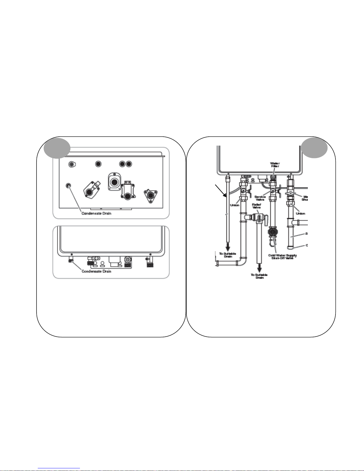
29 – Error Code
Explanation:
High Efficiency Condensing Units ONLY:
Condensate Drain is NOT draining.
CONDENSATE DRAIN DIAGNOSTICS:
1
Diagnostic Checks:
• Plug not removed from condensate drain
• Pinch in condensate drain line
• Blockage in condensate drain line
• Drain line has unnecessary “P” trap
2
Drain Line
Ensure you removed the condensate protection plug
located at bottom of unit.
Check your condensate drain line for internal or external
blockage. Make sure drain line is NOT pinched.
Page 60
60 | Page SVC 820 Tankless Gas Trouble Shooting Manual
60
Motor.
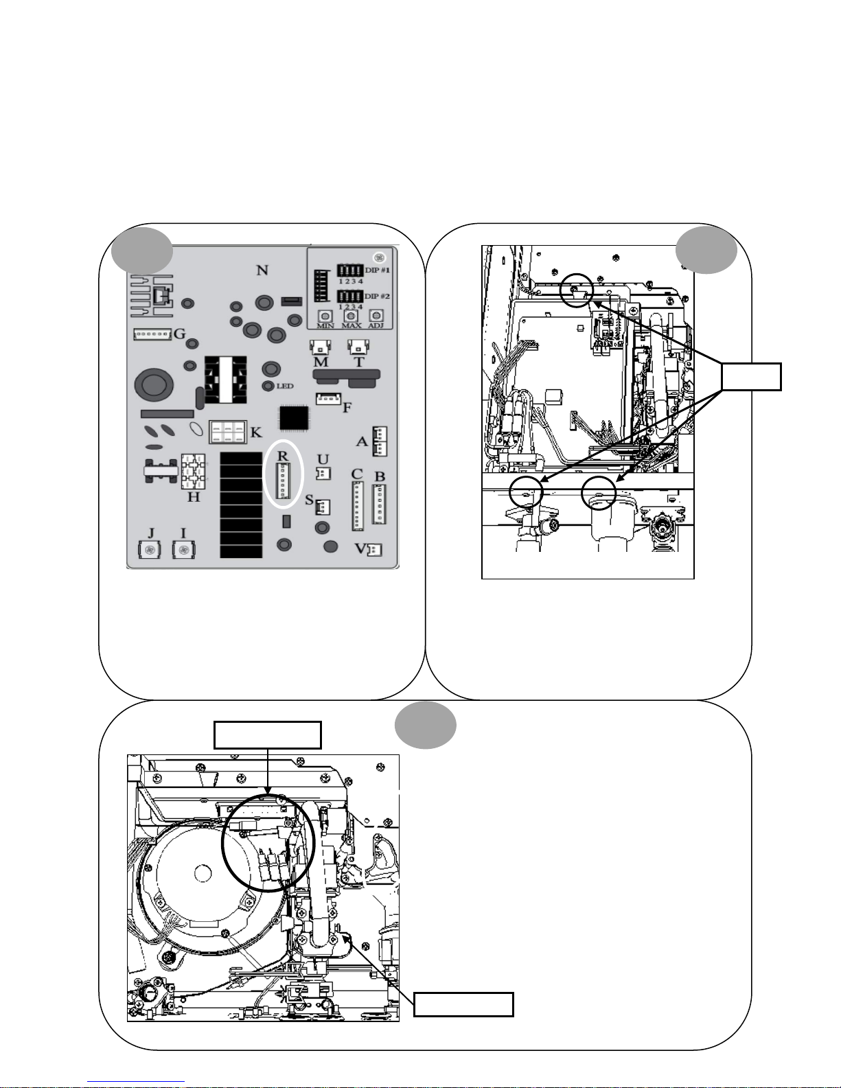
31 – Error Code
Explanation:
Inlet Thermistor malfunction
INLET THERMISTOR DIAGNOSTICS:
1
Diagnostic Checks:
• Inlet Thermistor
Control Board
2
Screws
Turn power OFF. Remove connector “R” on Control
Board. Measure resistance between Black #3 & white
#6 wires: 7K – 23K Ohms. IF OK, attempt to operate
unit again. IF 31 Error Code does NOT display, you had
a loose connection.
Molex Connectors
Blower Motor
Turn power OFF. Remove 3 screws for Control Board
mounting bracket. Remove connectors “M”, “T” &
“G”. Pull Control Board out of way to access WHITE
Molex for Inlet Thermistor located near the Blower
3
Separate top and bottom of WHITE
Molex for the Inlet Thermistor. Top of
Molex has 2 black wires and 1 white
wire. Bottom of Molex has 2 white
wires. Continue to Diagnostic Chart
Bottom of Unit
on next page.
Inlet Thermistor
Page 61
SVC 820-Tankless Gas Trouble Shooting Manual Page | 61
61
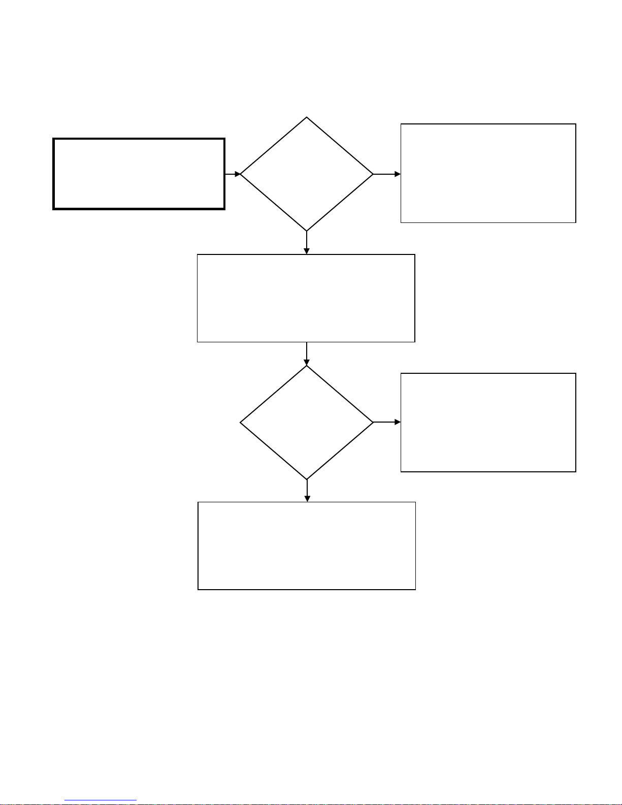
Clean scale build-up on Inlet Thermistor.
Retest Thermistor.
normal. Attempt to operate unit again.
YES
31 – Error Code Diagnostic Chart
Check the resistance across 2 white wires
on bottom Molex:
7K – 23K Ohms
Remove Molex from connector “R” at Control Board.
connector “R” and black wires at White Molex located
Check continuity from black #3 wire at Molex
behind Control Board. Check continuity from white
#6 wire at Molex connector “R” and white wire at
White Molex located behind Control Board
Is the resistance
to the Inlet
Thermistor OK?
IF tests OK, the water heater appears to be
NO
IF resistance NOT OK:
Replace Inlet Thermistor
Is the continuity
across all wires
OK?
YES
Attempt to operate unit again.
If the unit malfunctions due to an Error Code 31:
Replace Control Board
NO
Replace wiring harness for Connector “R”
on Control Board
Page 62
62 | Page SVC 820 Tankless Gas Trouble Shooting Manual
62
Bottom of Unit
Y:
32 – Error Code
Explanation:
Heat Exchanger Thermistor malfunction
HEAT EXHCANGER THERMISTOR DIAGNOSTICS:
1
Diagnostic Checks:
• Heat Exchanger Thermistor
2
Control Board
Screws
Turn power OFF. Remove connector “R” on Control
Board. Measure resistance between Black #3 & Yellow
#5 wires: 7K – 23K Ohms. IF OK, attempt to operate
unit again. IF 32 Error Code does NOT display, unit
had a loose connection.
Molex Connectors
Blower Motor
Turn power OFF. Remove 3 screws for Control Board
mounting bracket. Remove connectors “M”, “T” &
“G”. Pull Control Board out of way to access YELLOW*
Molex for Heat Exchanger Thermistor located near the
Blower Motor.
3
*High Efficiency (Condensing) Units ONL
Green wire & Green Molex
Separate top and bottom of YELLOW*
Molex for Heat Exchanger Thermistor.
Top of Molex has 2 black wires and 1
yellow* wire. Bottom of Molex has 2
white wires. Continue to Diagnostic
Chart on next page.
Page 63
SVC 820-Tankless Gas Trouble Shooting Manual Page | 63
63
Clean Scale Build-Up on Heat Exchanger
Thermistor. Retest Thermistor.
normal. Attempt to operate unit again.
IF resistance NOT OK:
igh Efficiency (Condensing) Units ONLY:
32 – Error Code Diagnostic Chart
Check the resistance across 2 white wires
on bottom Molex:
7k – 23K Ohms
Remove Molex from connector “R” at Control Board.
located behind Control Board. Check continuity from
Yellow* #5 wire at Molex connector “R” and Yellow*
Check continuity from black #3 wire at Molex
connector “R” and black wire at Yellow* Molex
wire at Yellow* Molex located behind Control Board
Is the resistance
to the Heat
Exchanger
Thermistor OK?
YES
NO
IF test OK, the water heater appears to be
Replace Heat Exchanger Thermistor
*H
Green wire & Green Molex
Is the continuity
across all wires
OK?
YES
Attempt to operate unit again.
If the unit malfunctions due to an Error Code 32:
Replace Control Board
NO
Replace wiring harness for Connector “R”
on Control Board
Page 64
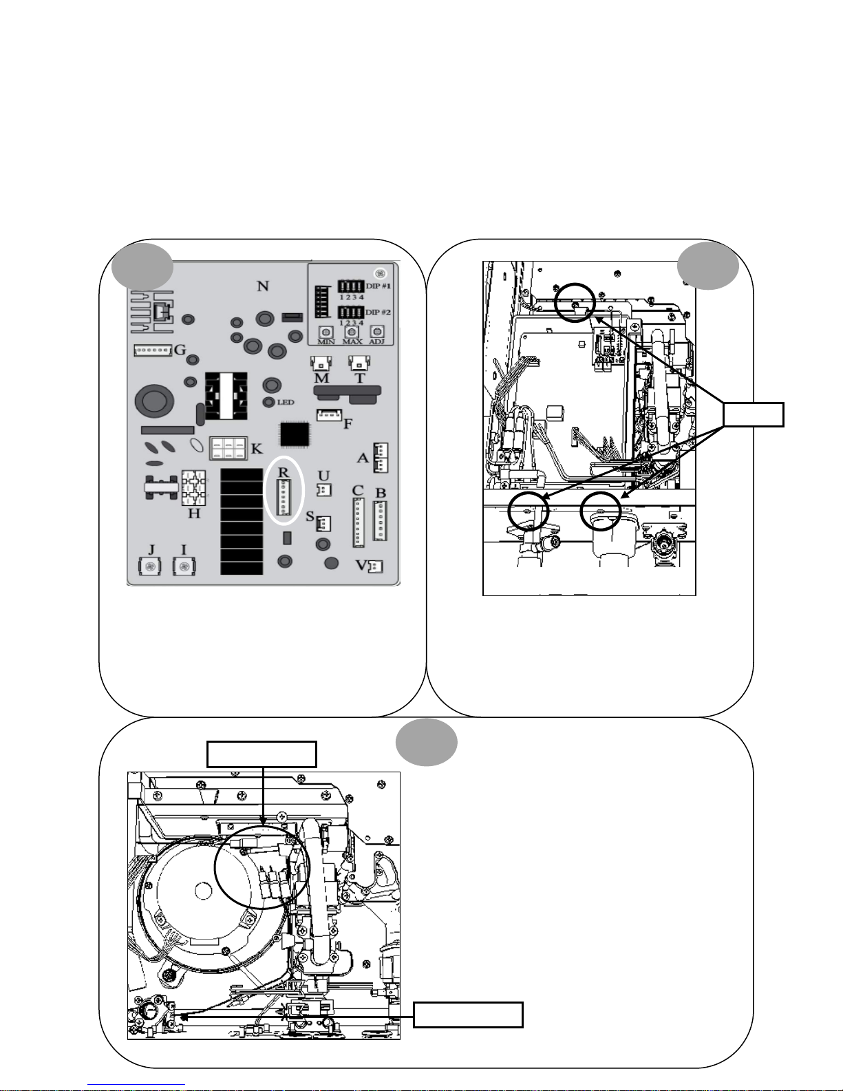
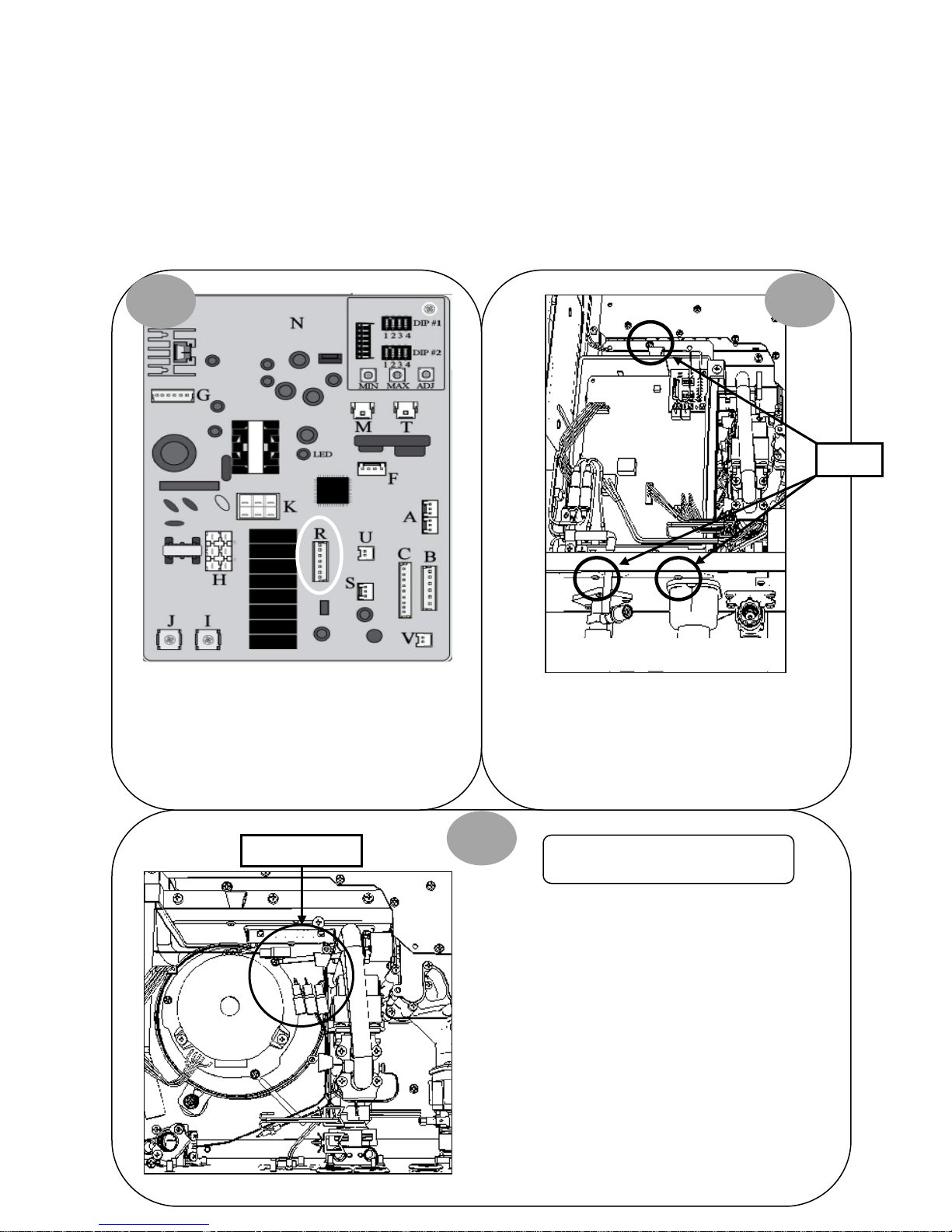
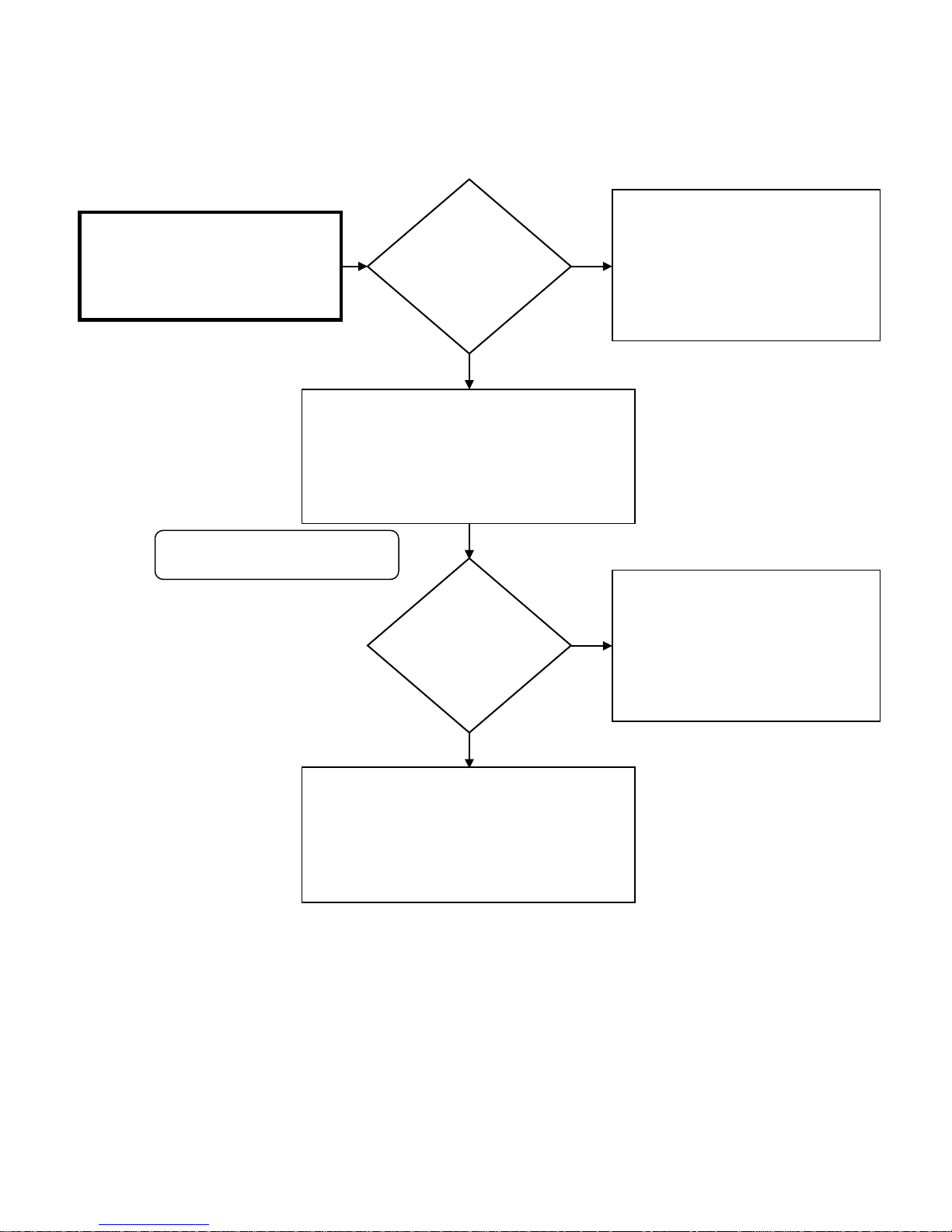
64 | Page SVC 820 Tankless Gas Trouble Shooting Manual
64
Screws
33 – Error Code
Explanation:
Outlet Thermistor malfunction
1
Diagnostic Checks:
• Outlet Thermistor
OUTLET THERMISTOR DIAGNOSTICS:
2
Control Board
Turn power OFF. Remove connector “R” on Control
Board. Measure resistance between Black #3 & Red
#4 wires: 7K – 23K Ohms. IF OK, attempt to operate
unit again. IF 33 Error Code does NOT display, unit
had a loose connection.
Molex Connectors
Blower Motor
Turn power OFF. Remove 3 screws for Control Board
mounting bracket. Remove connectors “M”, “T” &
“G”. Pull Control Board out of way to access BLACK
Molex for Outlet Thermistor located near the Blower
Bottom of Unit
Motor.
3
Separate top and bottom of BLACK
Molex for Outlet Thermistor. Top of
Molex has 2 black wires and 1 red
wire. Bottom of Molex has 2 black
wires. Continue to Diagnostic Chart
on next page.
Outlet Thermistor
Page 65
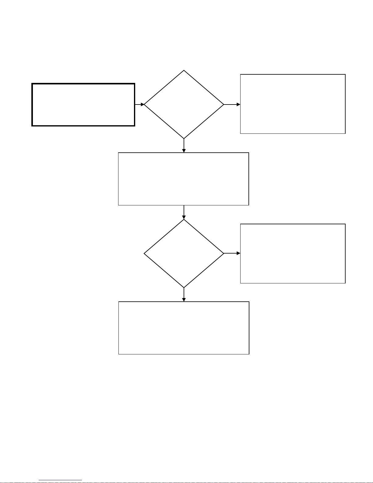
SVC 820-Tankless Gas Trouble Shooting Manual Page | 65
65
Clean Scale Build-Up on Outlet Thermistor.
33 – Error Code Diagnostic Chart
Check the resistance across 2 black wires
on bottom Molex:
7k – 23K Ohms
Remove Molex from Connector “R” at Control Board.
Check continuity from black #3 wire at Connector “R”
Molex and black wires at black Molex located behind
Is the resistance
to the Outlet
Thermistor OK?
YES
Control Board. Check continuity from red #4 wire at
Connector “R” Molex and red wire at Black Molex
located behind Control Board
Is the continuity
across all wires
OK?
NO
NO
Retest Thermistor. IF tests OK, the water
heater appears to be normal. Attempt to
operate unit again. IF resistance NOT OK:
Replace Outlet Thermistor
Replace wiring harness for Connector “R”
on Control Board
If the unit malfunctions due to an Error Code 33:
YES
Attempt to operate unit again.
Replace Control Board
Page 66
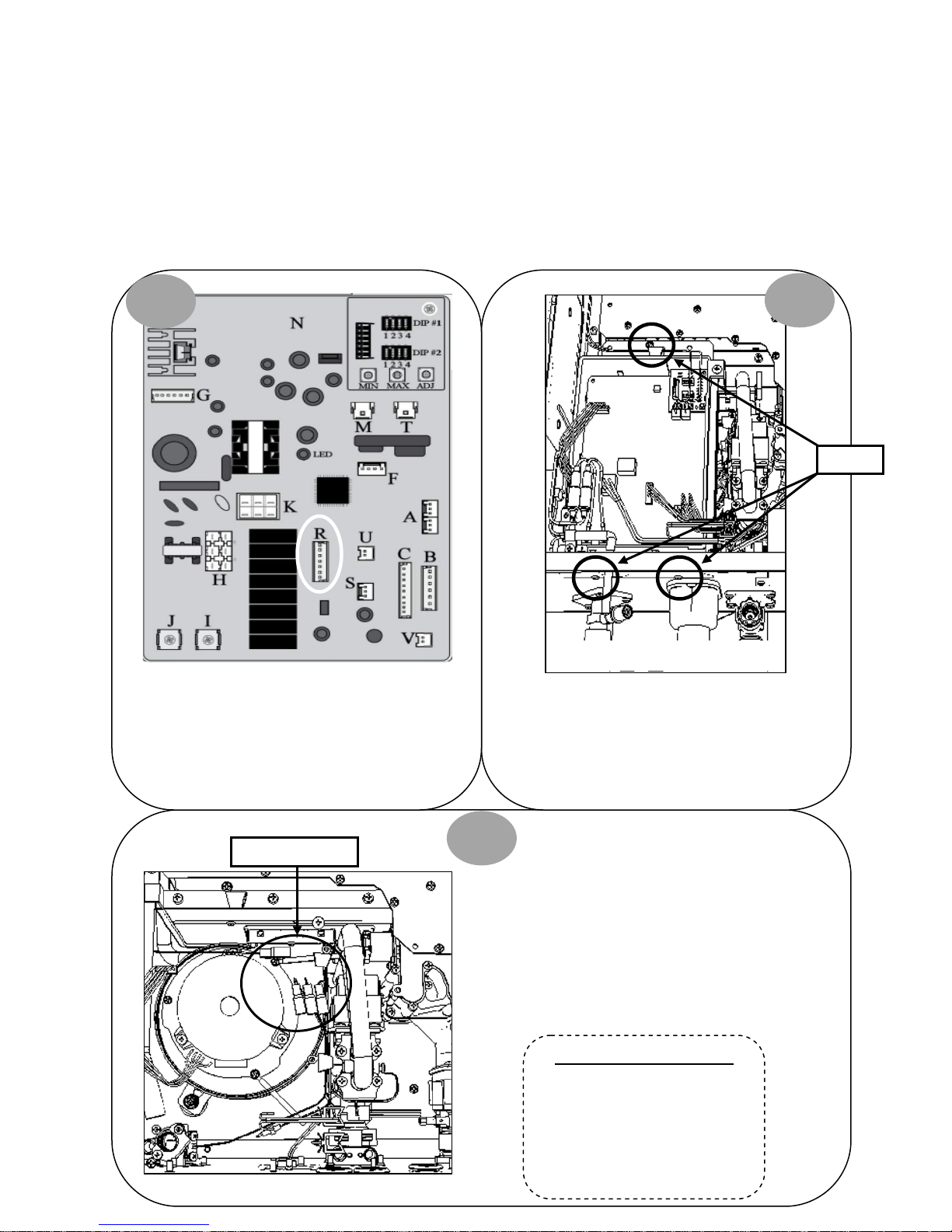
66 | Page SVC 820 Tankless Gas Trouble Shooting Manual
66
34 – Error Code
Explanation:
Ambient Thermistor malfunction
AMBIENT THERMISTOR DIAGNOSTICS:
1
Diagnostic Checks:
• Ambient Thermistor
2
Control Board
Screws
Turn power OFF. Remove connector “R” on Control
Board. Measure resistance between Black #3 & Blue
#7 wires: ‘Refer to Data Table for resistance value’. IF
OK, attempt to operate unit again. IF 34 Error Code
does NOT display, unit had a loose connection.
Molex Connectors
Blower Motor
Turn power OFF. Remove 3 screws for Control Board
mounting bracket. Remove connectors “M”, “T” &
“G”. Pull Control Board out of way to access BLUE
Molex for Ambient Thermistor located near the
Bottom of Unit
Blower Motor.
3
Separate top and bottom of BLUE
Molex for Ambient Thermistor. Top of
Molex has 2 black wires and 1 blue
wire. Bottom of Molex has 2 black
wires. Continue to Diagnostic Chart
on next page.
Ambient Thermistor Data Table
64DV; 84DV; 95DV: 7K – 23K Ohms
64X; 84X; 95X: 2K – 72K Ohms
H95DV; H95X: 2K – 72K Ohms
Page 67
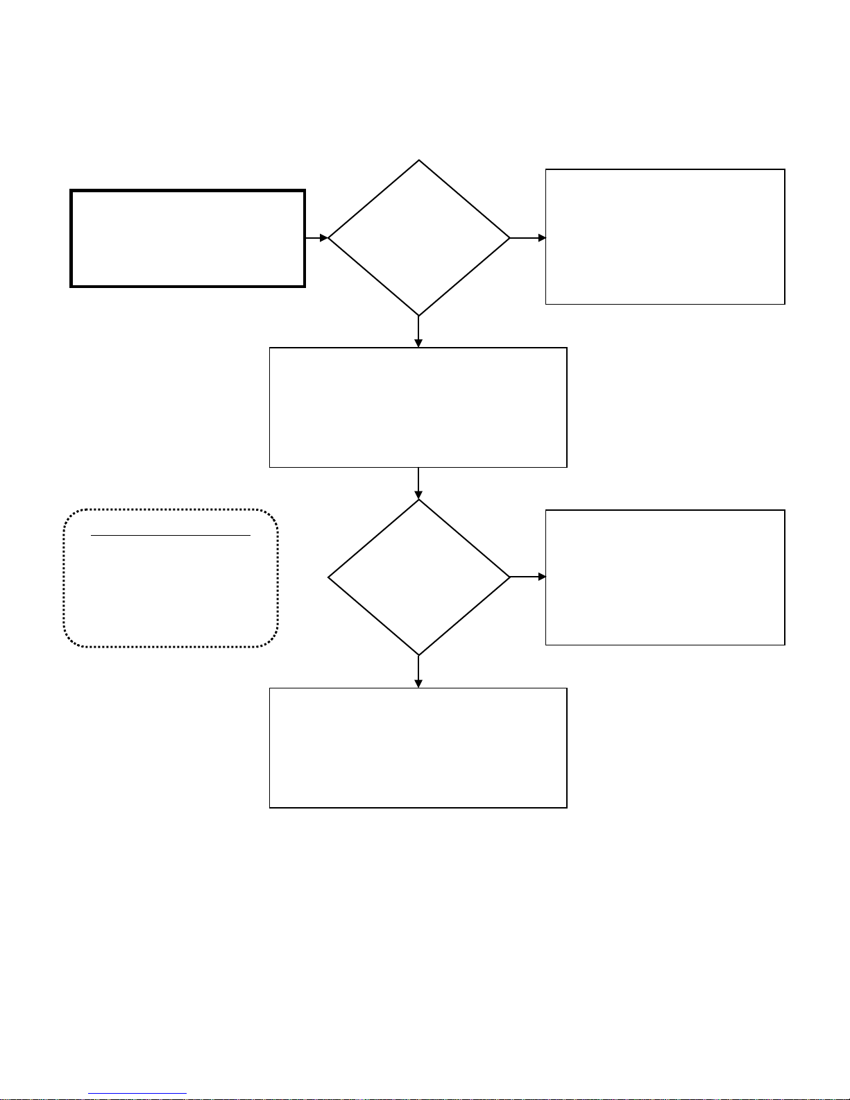
SVC 820-Tankless Gas Trouble Shooting Manual Page | 67
67
Clean Ambient Thermistor. Retest
34 – Error Code Diagnostic Chart
Check the resistance across 2 black wires
Ambient Thermistor Data Table
64DV; 84DV; 95DV: 7K – 23K Ohms
64X; 84X; 95X: 2K – 72K Ohms
on bottom Molex:
Refer to Data Table below
Is the resistance
to the Ambient
Thermistor OK?
YES
Remove Molex from Connector “R” at Control Board.
Check continuity from black #3 wire at Molex
connector “R” and black wires at Blue Molex located
behind Control Board. Check continuity from blue #7
wire at Molex connector “R” and blue wire at Blue
Molex located behind Control Board
Is the continuity
across all wires
OK?
NO
NO
Thermistor. IF tests OK, the water heater
appears to be normal. Attempt to operate
unit again. IF resistance NOT OK:
Replace Ambient Thermistor
Replace wiring harness for Connector “R”
on Control Board
H95DV; H95X: 2K – 72K Ohms
YES
Attempt to operate unit again.
If the unit malfunctions due to an Error Code 34:
Replace Control Board
Page 68
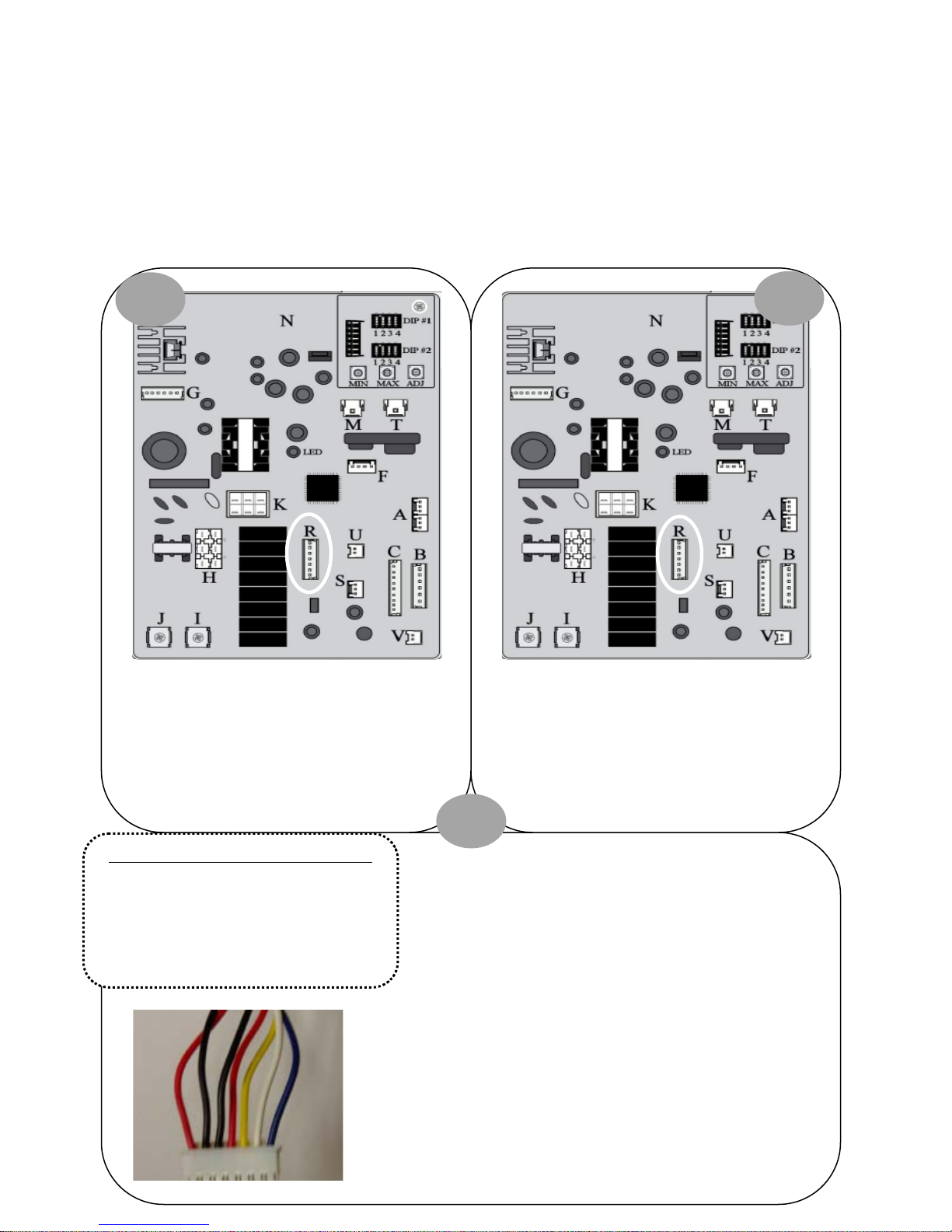
68 | Page SVC 820 Tankless Gas Trouble Shooting Manual
68
Inlet Thermistor
Heat Exchanger Thermistor
35 – Error Code
Explanation: Improper Thermistor connection. Unit has
four Thermistors; one or more possibly has a poor
connection or not connected in proper location.
THERMISTORS DIAGNOSTICS:
1
Diagnostic Checks:
• Inlet, Heat Exchanger, Outlet, and Ambient
Thermistors.
2
Turn power OFF. Remove and reinsert connector “R”
on Control Board. Attempt to operate unit again. IF
35 Error Code does NOT display, unit had a loose
connection.
Black #3 & Blue #7 Wires: Ambient Thermistor
64DV; 84DV; 95DV: 7K – 23K Ohms
64X; 84X; 95X: 2K – 72K Ohms
H95DV; H95X: 2K – 72K Ohms
Turn power OFF. Remove connector “R” on Control
Board. Measure the resistance for all temperature
sensors (step 3). IF temperature sensor FAILS the
resistance check, go to the appropriate Error Code for
diagnostics. IF sensors test ‘OK’ continue to next page.
3
Black #3 & White #6 Wires:
7K – 23K Ohms. Error Code 31
Black #3 & Yellow #5 Wires:
7K – 23K Ohms. Error Code 32
Black #3 & Red #4 Wires: Outlet Thermistor
7K – 23K Ohms. Error Code 33
Black #3 & Blue #7 Wires: Ambient Thermistor
Refer to Data Table. Error Code 34
Page 69
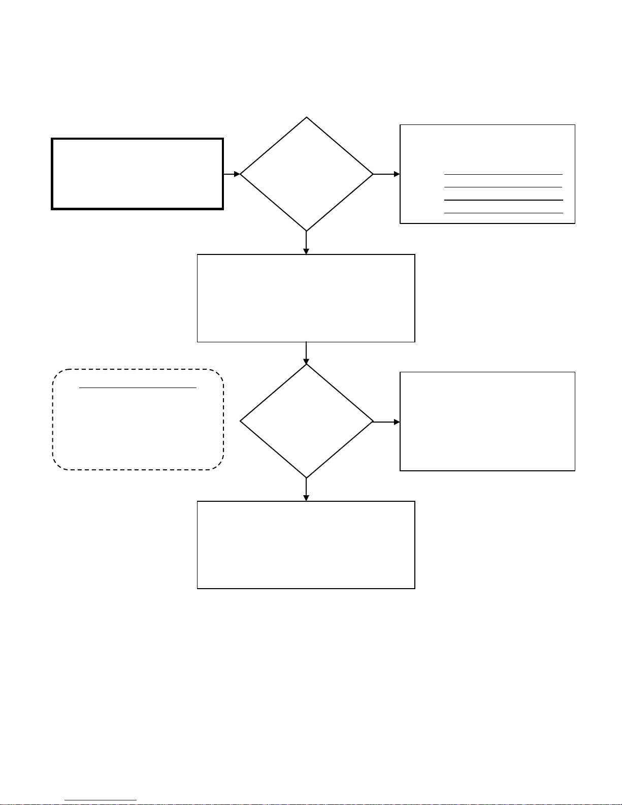
SVC 820-Tankless Gas Trouble Shooting Manual Page | 69
69
35 – Error Code Diagnostic Chart
Check resistance for all Thermistors at
Molex Connector “R”
Ambient Thermistor Data Table
64DV; 84DV; 95DV: 7K – 23K Ohms
64X; 84X; 95X: 2K – 72K Ohms
Is the resistance
for all
Thermistors OK?
YES
Attempt to operate the unit again
Did the unit
lockout on Error
Code 35?
NO
NO
Go to appropriate Sensor Error Code to
diagnose:
1. Inlet: Error Code 31
2. Heat Exchanger: Error Code 32
3. Outlet: Error Code 33
4. Ambient: Error Code 34
The water heater appears to be operating
normally
H95DV; H95X: 2K – 72K Ohms
YES
Replace Control Board
Page 70
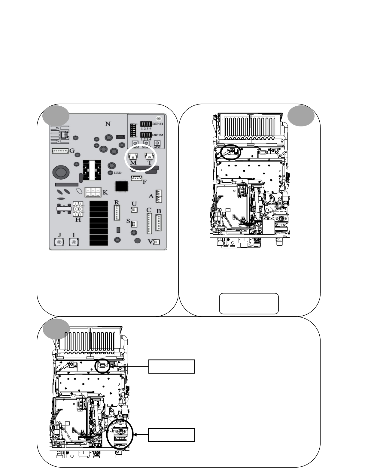
70 | Page SVC 820 Tankless Gas Trouble Shooting Manual
70
Remove and reinsert terminals on Fame Rod(s)*.
right side of unit.
51 – Error Code
Explanation: Gas Control Valve malfunction. The unit
detects the presence of flame when the demand for hot
water is terminated and burner is OFF. This error code
will only occur at time of shut down.
Diagnostic Checks:
• Flame Rods(s)
• Gas Control Valve
FLAME RODS & GAS VALVE DIAGNOSTICS:
1 2
Turn power OFF. Remove and reinsert white
connector “M” and blue connector “T” on Control
Board.
3
Sight Glass
Attempt to operate unit again. IF 51 Error Code does
NOT display, unit had a loose connection.
Visually inspect Gas Control Valve
connections or damaged wiring.
Gas Control Valve is located on lower
*Indoor Models ONLY:
2 Flame Rods
wiring harnesses for loose
Locate sight glass.
Gas Control Valve
Page 71
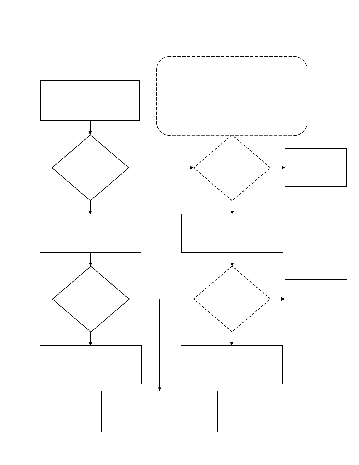
SVC 820-Tankless Gas Trouble Shooting Manual Page | 71
71
While viewing burner chamber through
sight glass:
heater 3 times by turning unit
“on – off; on – off; on – off”
Is debris visible
ode
ode
Attempt to operate unit again. If the unit
.
Indoor Units: 05
51 – Error Code Diagnostic Chart
In 10 second intervals; cycle the water
Visibly inspect burner chamber through
Is there a visible
flame while unit
is OFF?
YES
Sight Glass
On Remote Control, go to Maintenance Mode 0Y table. For
Maintenance Mode instructions go to page 16
All Maintenance Mode ‘0Y’ readings should be done
immediately after turning the unit OFF. IF Flame Rod(s) is
detecting flame, Maintenance Mode will display:
Outdoor Units: 01
Does ‘OY’ Status in
NO
Disconnect Molex Connector from Flame
Rods(s). Cycle the water heater 3 times by
turning unit “on – off; on – off; on – off”
Maintenance M
indicate presence
of flame after 5
seconds?
YES
Water heater appears
NO
to be normal.
Attempt to operate unit
again
on burner
assembly?
YES
Remove and clean burner assembly
Attempt to operate unit again. If the unit
displays 51 Error Code and flame IS visible while
NO
unit is OFF:
Replace Gas Control Valve
Does ‘OY’ Status in
Maintenance M
indicate presence
of flame after 5
seconds?
YES
malfunctions due to an Error Code 51:
Replace Control Board
NO
Clean or Replace Flame
Rod(s)
Page 72
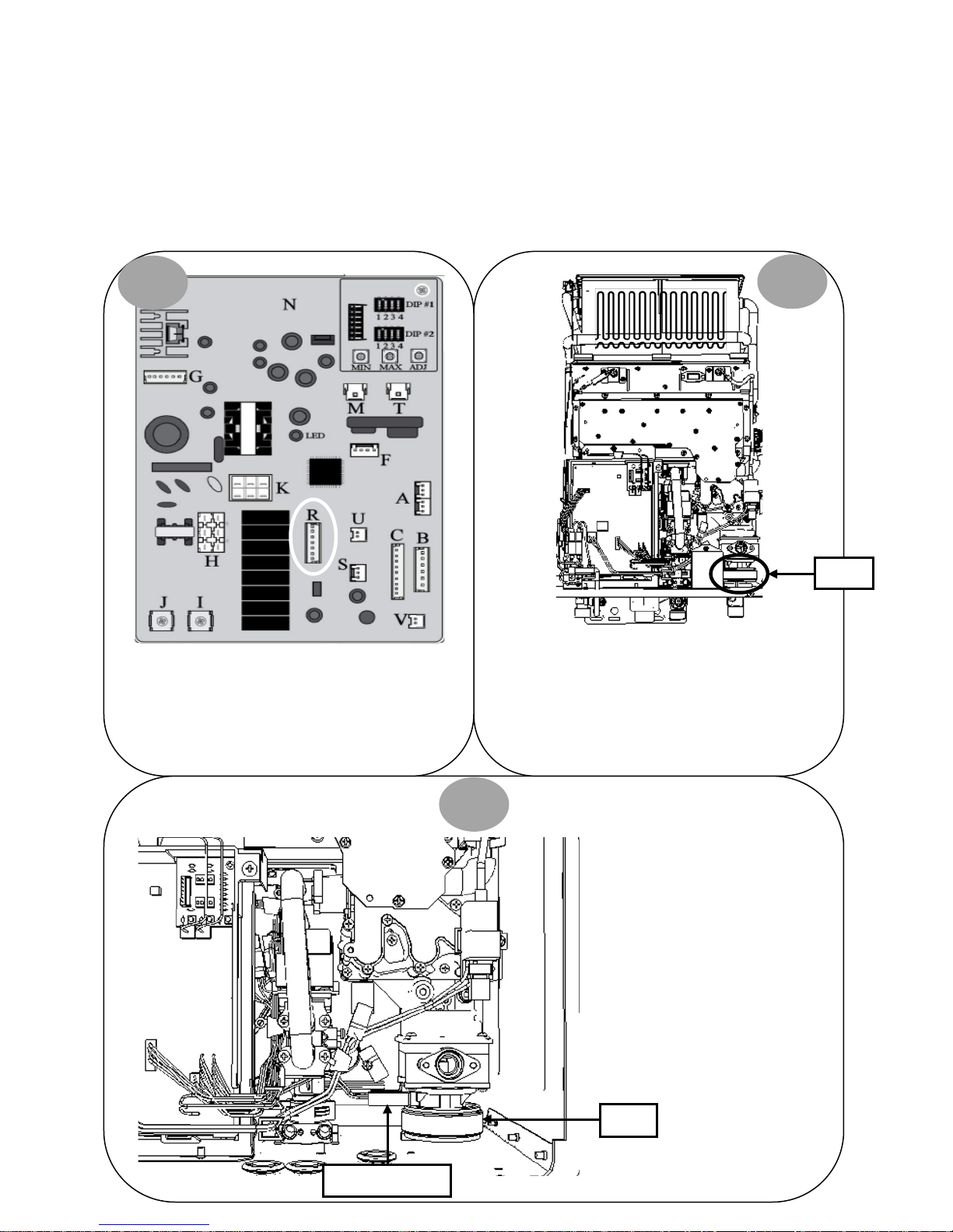
72 | Page SVC 820 Tankless Gas Trouble Shooting Manual
72
52 – Error Code
Explanation: PGFR (Proportional Gas Flow Regulator)
malfunction. The PGFR is the only modulating valve in the
Gas Control Valve.
PGFR DIAGNOSTICS:
1
Turn power OFF. Remove and reinsert connector “R”
on Control Board.
Diagnostic Checks:
• PGFR
2
PGFR
Locate PGFR valve on lower right of unit. Remove and
reinsert Molex connector with red wire and Molex
connector with black wire on PGFR. Attempt to
operate unit again.
Control Board
Molex Connectors
3
IF 52 Error Code does NOT display,
unit had a loose connection.
IF 52 Error Code IS displayed,
continue to diagnostic chart on next
page.
PGFR
Page 73
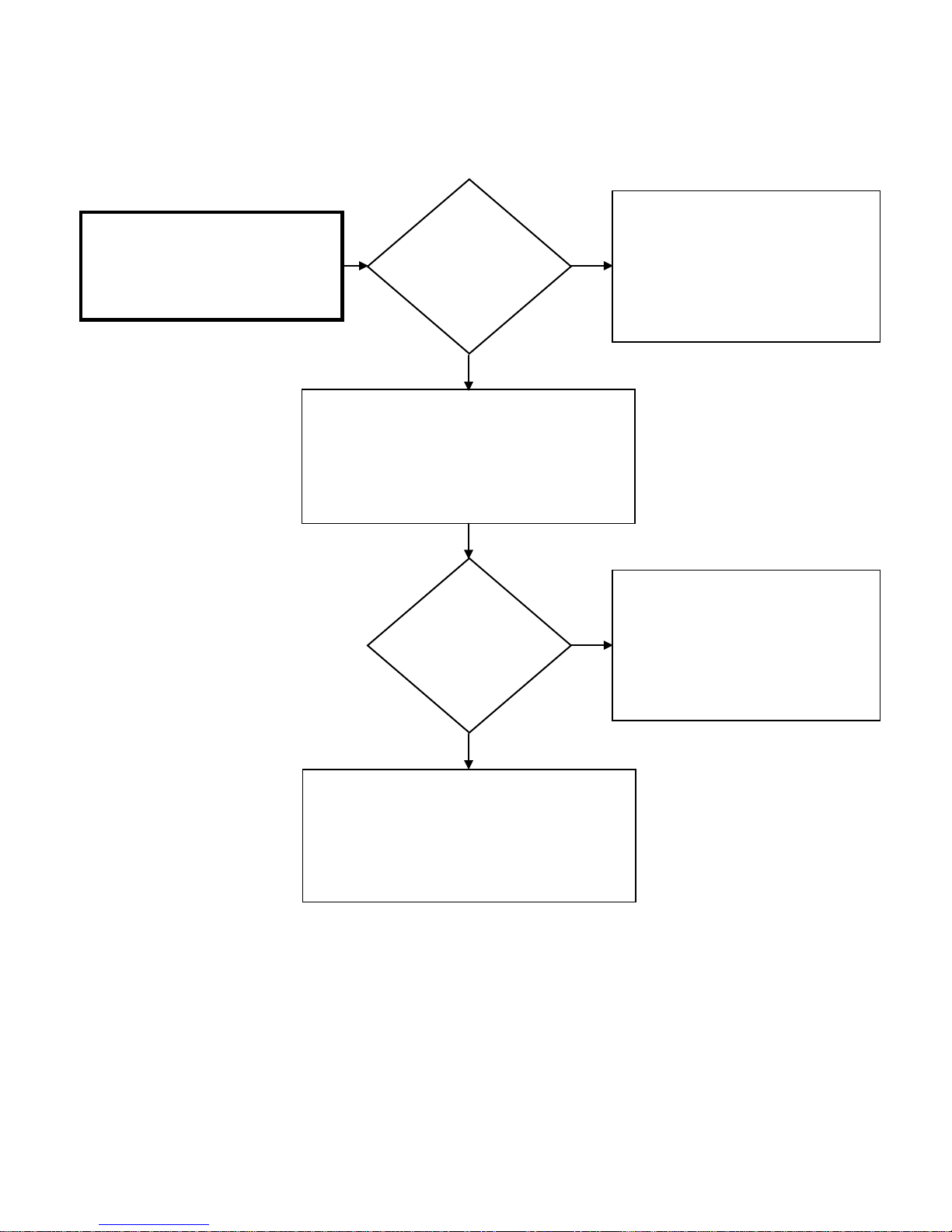
SVC 820-Tankless Gas Trouble Shooting Manual Page | 73
73
52 – Error Code Diagnostic Chart
While unit is attempting to go to main
burner, check DC voltage across red wire
#1 and black wire #2 on Connector “R”:
1.5 – 14 DC VOLTS
Is the DC voltage
OK?
YES
While unit is attempting to go to main burner, check
DC voltage across red and black wires at PGFR:
1.5 – 14 DC VOLTS
Is the DC voltage
OK?
NO
NO
Attempt to operate unit again.
If the unit malfunctions due to an Error
Code 52:
Replace Control Board
Replace wiring harness for Connector “R”
on Control Board
YES
Attempt to operate unit again.
If the unit malfunctions due to an Error Code 52:
Replace Gas Control Valve
Page 74
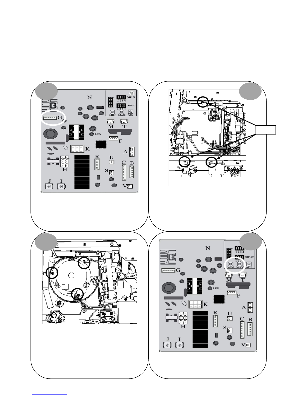
74 | Page SVC 820 Tankless Gas Trouble Shooting Manual
74
61 – Error Code
Explanation: Blower Motor malfunction. Blower Motor
speed was not appropriate to allow proper combustion.
Diagnostic Checks:
• Blower Motor
BLOWER MOTOR DIAGNOSTICS:
1 2
Control Board
Bottom of Unit
Turn power OFF. Remove 3 screws for Control Board
Turn power OFF. Remove and reinsert connector “G”
on Control Board. Attempt to operate unit again. IF
61 Error Code does NOT display, unit had a loose
connection.
mounting bracket. Remove connectors “M”, “T” &
“G”. Pull Control Board out of way to access Blower
Motor.
Screws
3
Blower Motor
Remove 3 screws holding Blower Motor in place.
Clean Blower Motor and reassemble unit. Attempt to
operate unit again. IF 61 Error Code does NOT
display: Blower Motor needed to be cleaned.
4
Locate Min & Max buttons on Control Board.
Continue to diagnostic chart on next page.
Page 75
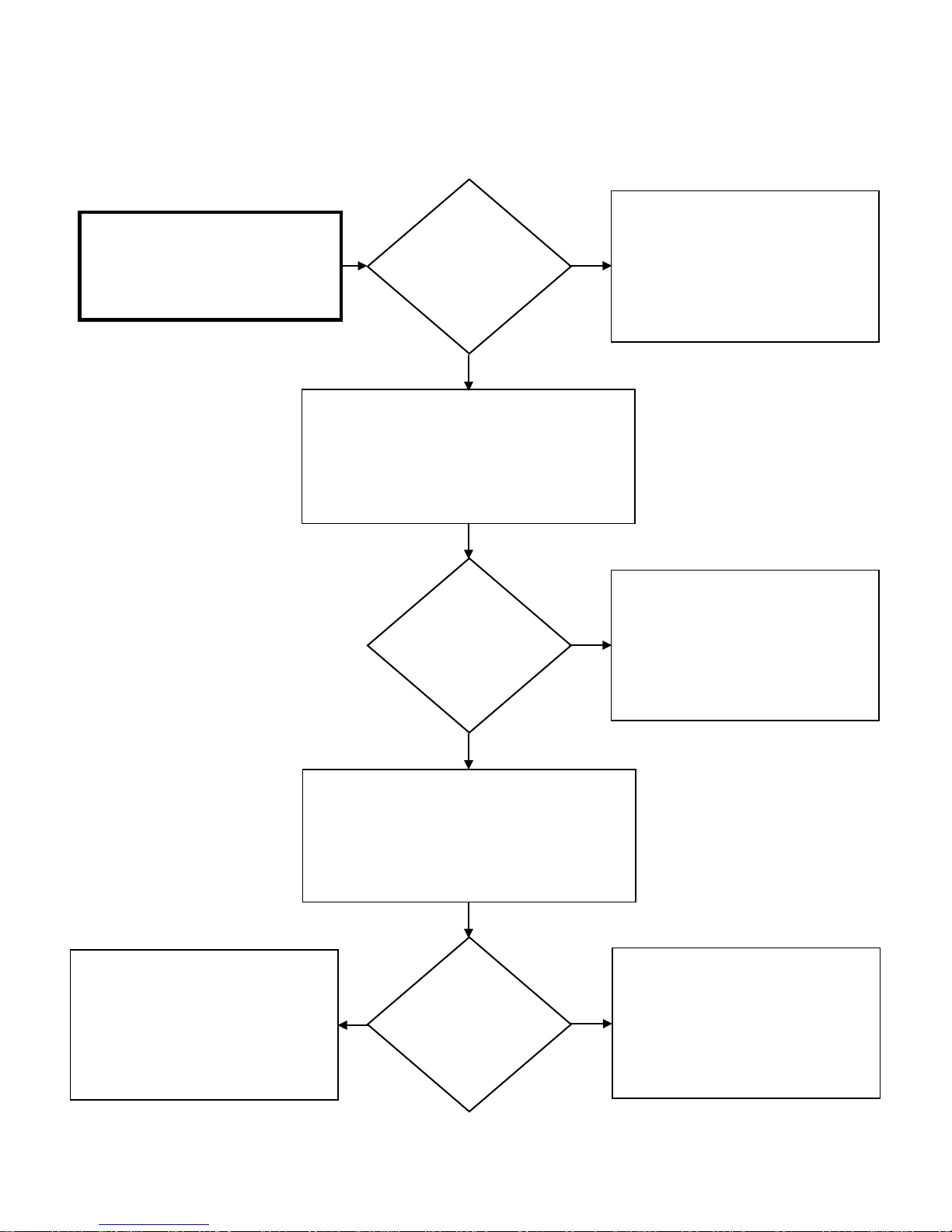
SVC 820-Tankless Gas Trouble Shooting Manual Page | 75
75
Attempt to operate unit again.
Attempt to operate unit again.
61 – Error Code Diagnostic Chart
Test DC voltage across black and red
wires on Molex connector “G”:
144 – 192 DC VOLTS
Press and hold down “MAX” button on Control Board
test DC voltage across black and white wires on Molex
Is the DC voltage
OK?
YES
to activate Blower Motor. While Blower is running,
connector “G”:
12 – 18 DC VOLTS
Is the DC voltage
OK?
NO
NO
Remove and reinsert connector “G”.
If the unit malfunctions due to an Error
Code 61:
Replace Control Board
Remove and reinsert connector “G”.
If the unit malfunctions due to an Error
Code 61:
YES
Press and hold down “MAX” button on Control Board
to activate Blower Motor. While Blower is running,
test DC voltage across black and blue wires on Molex
connector “G”:
4 – 10 DC VOLTS
Attempt to operate unit again.
If the unit malfunctions due to an Error
Code 61:
Replace Control Board
YES NO
Is the DC voltage
OK?
Replace Control Board
Replace Blower Motor
Page 76
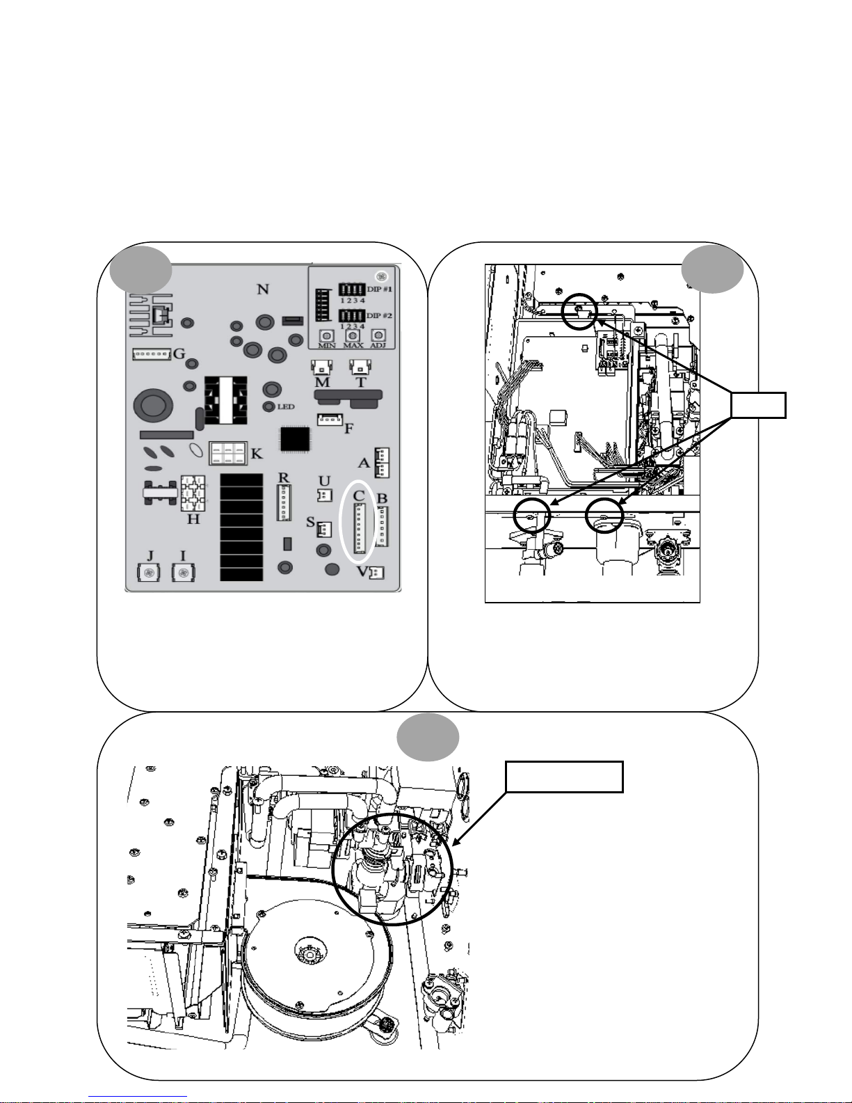
76 | Page SVC 820 Tankless Gas Trouble Shooting Manual
76
Blower Motor
65 – Error Code
Explanation: Water Control Valve malfunction
WATER CONTROL VALVE DIAGNOSTICS:
1
Diagnostic Checks:
• Water Control Valve
Control Board
2
Screws
Turn power OFF. Remove and reinsert connector “C”
on Control Board. Attempt to operate unit again. IF
65 Error Code does NOT display, unit had a loose
connection.
Top of Unit
Turn power OFF. Remove 3 screws for Control Board
mounting bracket. Remove connectors “M”; “T” &
“G”. Pull Control Board out of way to access Water
Bottom of Unit
Control Valve.
3
Water Control Valve
Visually inspect Water Control Valve
wiring harness for loose or damaged
terminals. It is located right of the
Blower Motor; connected directly to
the water inlet. Reassemble unit and
Bottom of Unit
continue to diagnostic chart on next
page.
Page 77
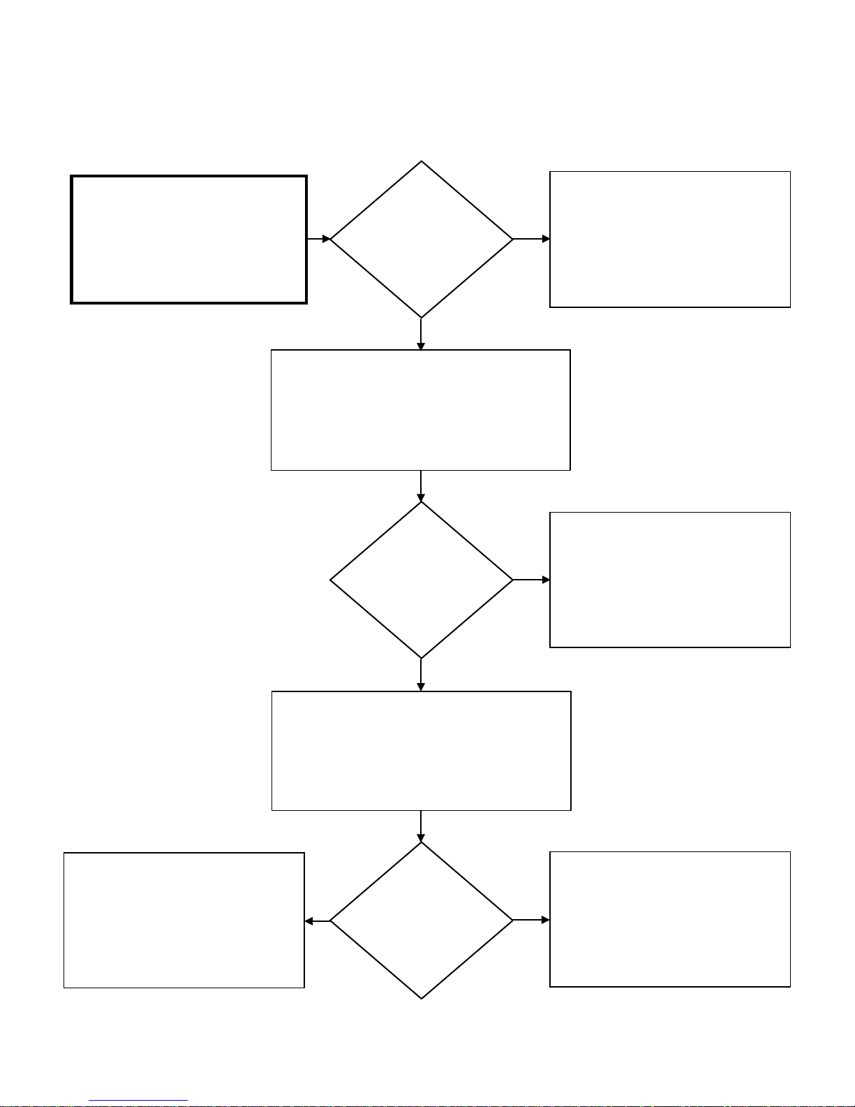
SVC 820-Tankless Gas Trouble Shooting Manual Page | 77
77
65 – Error Code Diagnostic Chart
While water is flowing and unit is
attempting to ignite; check DC Voltage
across White & Black Wires at
connector “C”:
8 – 16 DC VOLTS
Is the DC voltage
OK?
YES
Turn power to unit OFF then ON again and turn water
flow on. Check DC Voltage across Red & Black Wires
at connector “C”:
8 – 16 DC VOLTS
Is the DC voltage
OK?
NO
NO
Attempt to operate unit again.
If the unit malfunctions due to an Error
Code 65:
Replace Control Board
Attempt to operate unit again.
If the unit malfunctions due to an Error
Code 65:
Attempt to operate unit again.
If the unit malfunctions due to an Error
Code 65:
Replace Water Control Valve
YES
Turn power to unit OFF then ON again and turn water
flow on. Check DC Voltage across Green & Black
Wires at connector “C”:
4 – 6 DC VOLTS
Is the DC voltage
YES
OK?
NO
Replace Control Board
Attempt to operate unit again.
If the unit malfunctions due to an Error
Code 65:
Replace Control Board
Page 78
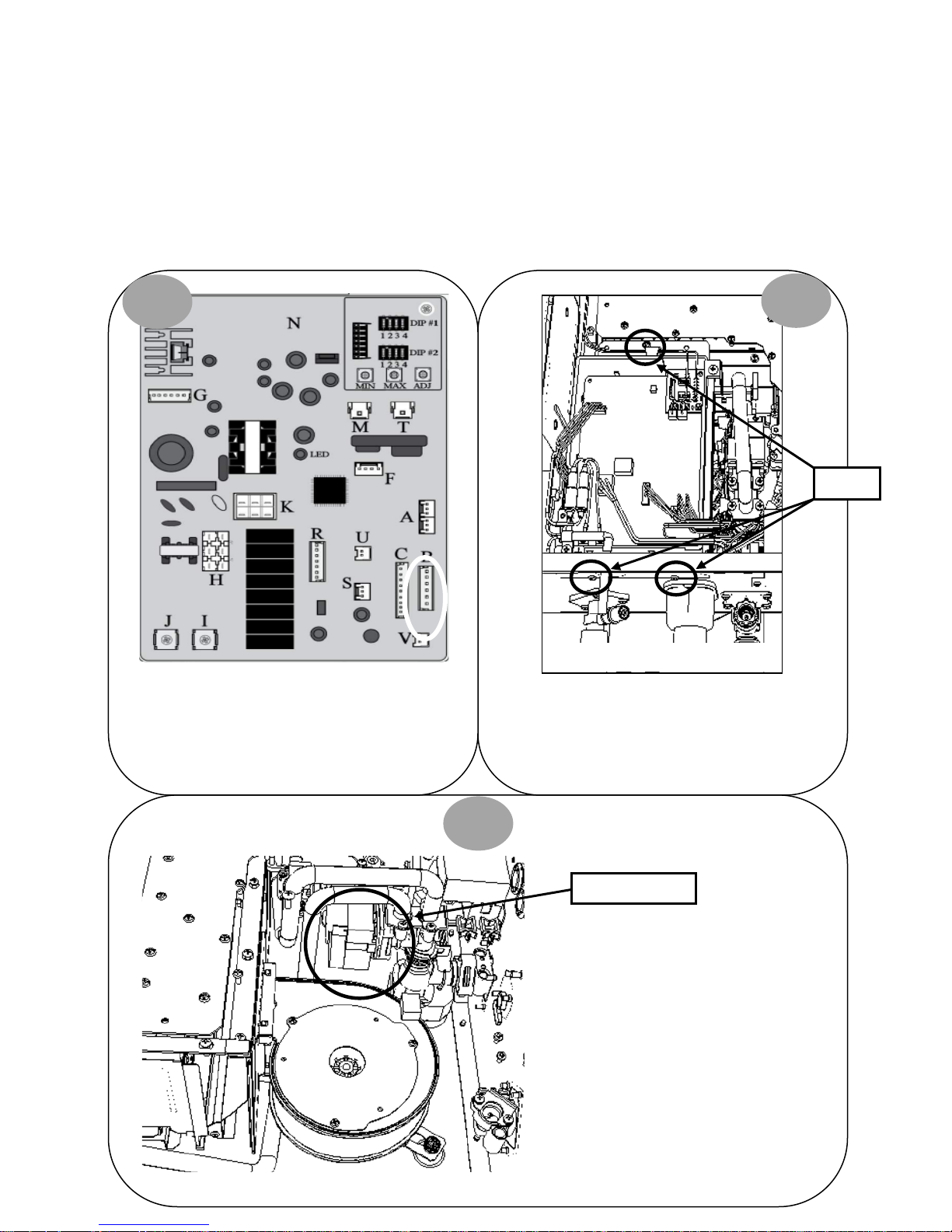
78 | Page SVC 820 Tankless Gas Trouble Shooting Manual
78
Top of Unit
66 – Error Code
Explanation: Water Bypass Valve malfunction. Hot outlet
water temperature is above or below set point on Remote
Control.
WATER BYPASS VALVE DIAGNOSTICS:
•
1
Diagnostic Checks:
• Water Bypass Valve
2
Control Board
Screws
Turn power OFF. Remove and reinsert connector “B”
on Control Board. Attempt to operate unit again. IF
66 Error Code does NOT display, unit had a loose
connection.
Turn power OFF. Remove 3 screws for Control Board
mounting bracket. Remove connectors “M”; “T”; &
“G”. Pull Control Board out of way to access Water
Bottom of Unit
Bypass Valve.
3
Water Bypass Valve
Visually inspect Water Bypass Valve
wiring harness for loose or damaged
terminals. It is located right of the
Blower Motor; below two copper
Bottom of Unit
pipes. Reassemble unit and continue
to diagnostic chart on next page.
Blower Motor
Page 79
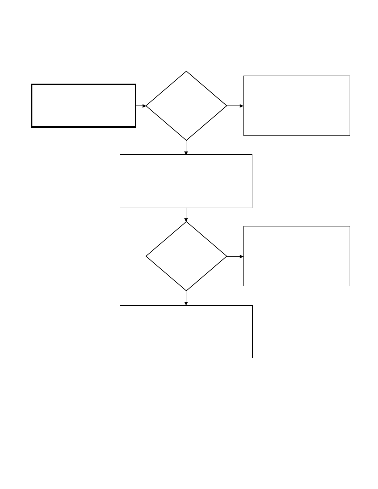
SVC 820-Tankless Gas Trouble Shooting Manual Page | 79
79
connector “B”:
8 – 16 DC VOLTS
66 – Error Code Diagnostic Chart
Turn Remote Control OFF; unplug unit
and then ON again. Check DC voltage
across red and black wires on Molex
Is the DC voltage
OK?
YES
While Water Bypass Valve is operating (water is
flowing), check DC voltage across red and black wires
at Water Bypass Valve wiring harness:
8 – 16 DC VOLTS
Is the DC voltage
OK?
NO
NO
Attempt to operate unit again.
If the unit malfunctions due to an Error
Code 66:
Replace Control Board
Attempt to operate unit again.
If the unit malfunctions due to an Error
Code 66:
YES
Attempt to operate unit again. If the unit
malfunctions due to an Error Code 66:
Replace Water Bypass Valve
Replace Control Board
Page 80
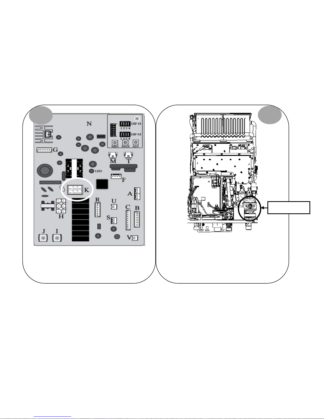
80 | Page SVC 820 Tankless Gas Trouble Shooting Manual
80
on lower right side of unit.
71 – Error Code
Explanation: Gas Control Valve malfunction
Diagnostic Checks: Gas Control Valve
GAS CONTROL VALVE DIAGNOSTICS:
1
Turn power OFF. Remove and reinsert connector “K” on
Control Board. Attempt to operate unit again. IF 71 Error
Code does NOT display, unit had a loose connection.
2
Gas Control Valve
Visually inspect Gas Control Valve wiring harnesses for
loose or damaged terminals. Gas Control Valve is located
Continue to diagnostic chart on next page.
Page 81
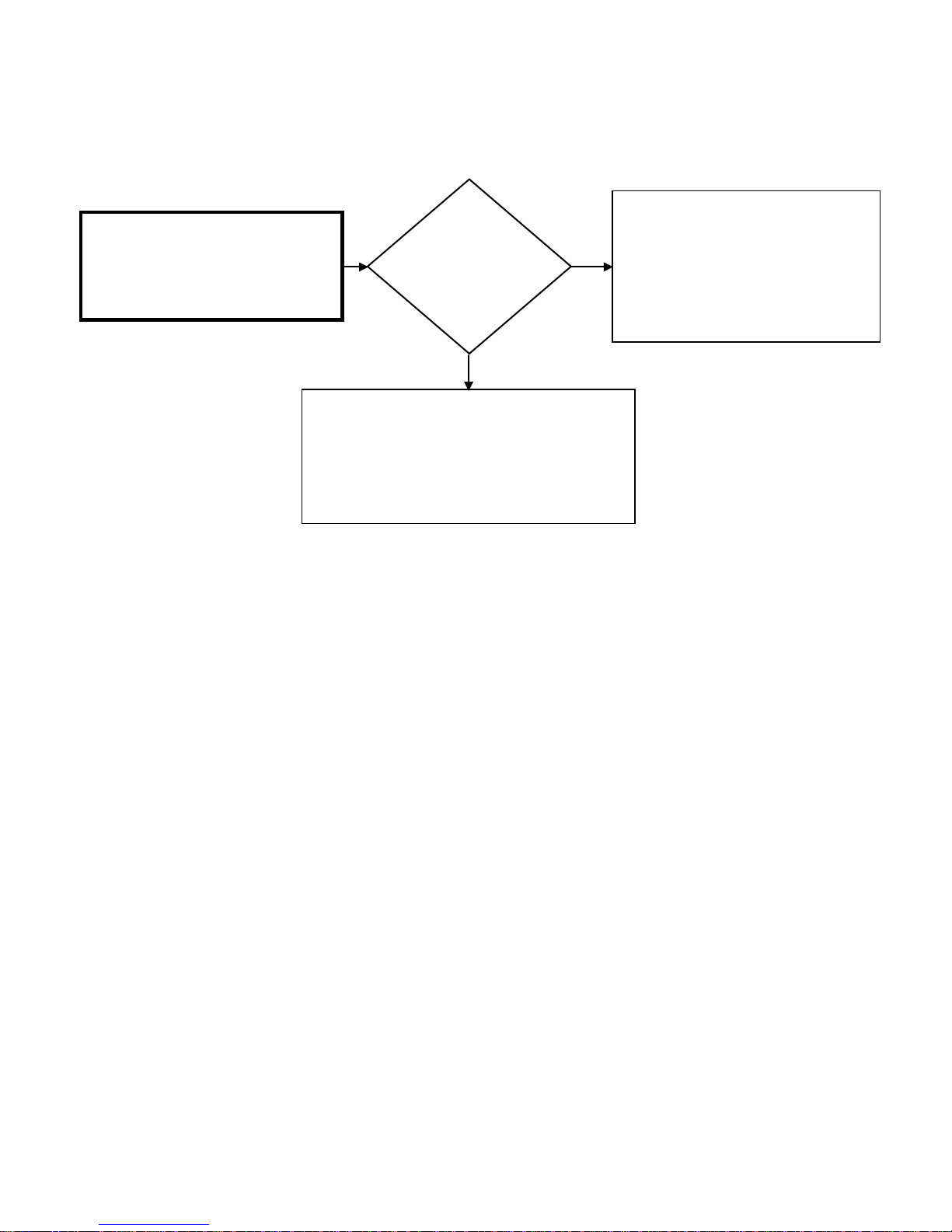
SVC 820-Tankless Gas Trouble Shooting Manual Page | 81
81
71 – Error Code Diagnostic Chart
While unit is attempting to go to ignite,
check DC voltage across yellow and black
wires on Molex connector “K”:
75 – 100 DC VOLTS
Reset the water heater and attempt to operate again.
Is the DC voltage
OK?
YES
If the unit malfunctions due to an Error Code 71:
Replace Gas Control Valve
NO
Attempt to operate again.
If the unit malfunctions due to an Error
Code 71:
Replace Control Board
Page 82
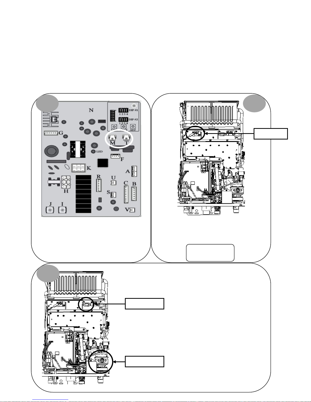
82 | Page SVC 820 Tankless Gas Trouble Shooting Manual
82
Remove and reinsert terminals on Flame Rod(s)*.
72 – Error Code
Explanation: Flame Rod(s) malfunction. Flame Rod(s) is
detecting the presence of flame BEFORE igniter is
activated.
Diagnostic Checks:
• Flame Rod(s)
• Gas Control Valve
FLAME ROD(s) & GAS CONTROL VALVE DIAGNOSTICS:
1 2
Flame Rod(s)*
Turn power OFF. Remove and reinsert white
connector “M” and blue connector “T” on Control
Board.
3
Gas Control Valve
Sight Glass
Attempt to operate unit again. IF 72 Error Code does
NOT display, unit had a loose connection.
*Indoor Units ONLY:
Visually inspect Gas Control Valve
wiring harnesses for loose
connections or damaged wiring.
Gas Control Valve is located on
lower right side of unit.
Locate Sight Glass.
2 Flame Rods
Page 83
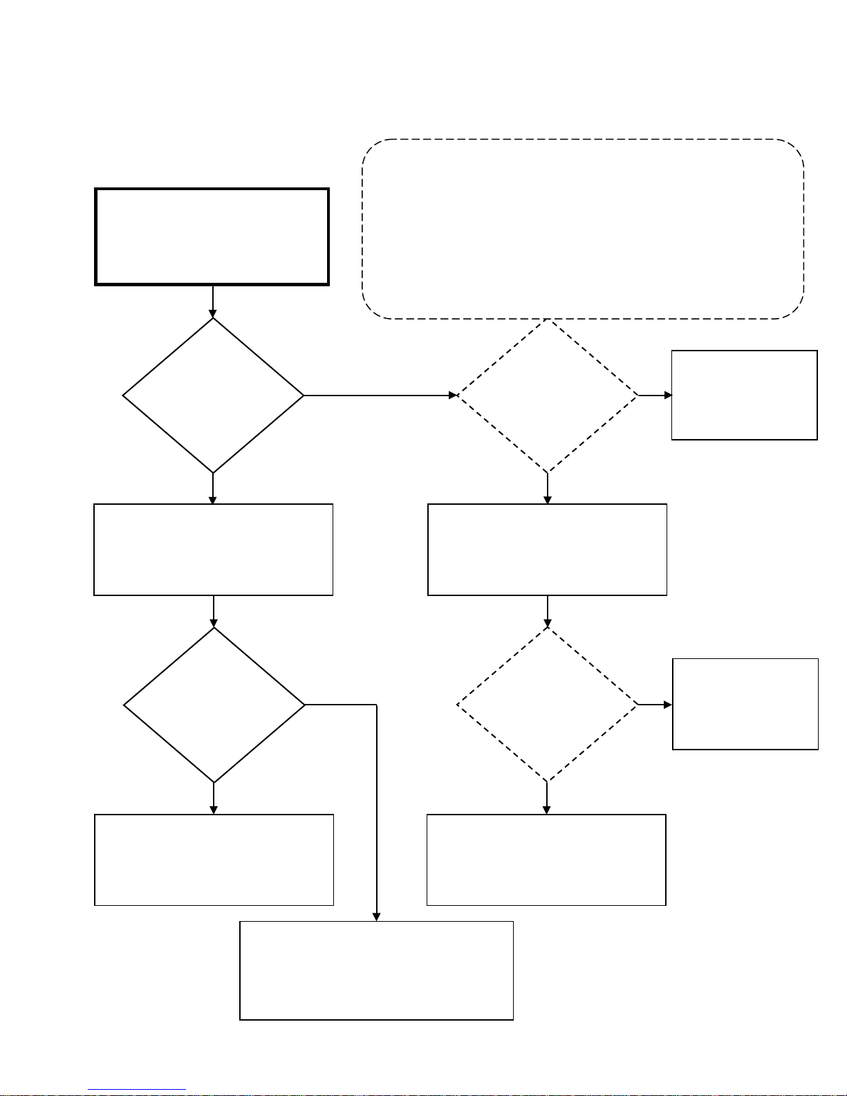
SVC 820-Tankless Gas Trouble Shooting Manual Page | 83
83
on water flow to begin ignition sequence
Is debris visible
ode
ode
Attempt to operate again.
ON. IF flame sensor IS detecting flame, Maintenance Mode will display:
Indoor Units: 05
72 – Error Code Diagnostic Chart
Turn power OFF. Unplug unit and plug
back in. Turn power ON. While viewing
burner chamber through sight glass, turn
Visibly inspect burner chamber through
Is there a visible
flame before
Igniter Rod
sparks?
YES
sight glass
On Remote Control, go to Maintenance Mode 0Y table. For Maintenance Mode
instructions go to page 16.
All Maintenance Mode ‘0Y’ readings should be done immediately after turning
the unit
Outdoor Units: 01
NO
Does ‘OY’ Status in
Maintenance M
indicate presence
of flame?
YES
Turn power OFF. Unplug unit. Disconnect
Molex connector(s) from Flame Rod(s).
Plug unit in. Turn power ON. Turn water
flow ON to begin ignition sequence
NO
Water heater appears
to be normal.
Attempt to operate
again
on burner
assembly?
YES
Remove and clean burner assembly
Attempt to operate again. If unit displays 72
Error Code and flame IS visible while unit is OFF:
NO
Replace Gas Control Valve
Does ‘OY’ Status in
Maintenance M
indicate presence
of flame?
YES
If unit displays 72 Error Code:
Replace Control Board
NO
Clean or Replace Flame
Rod(s)
Page 84
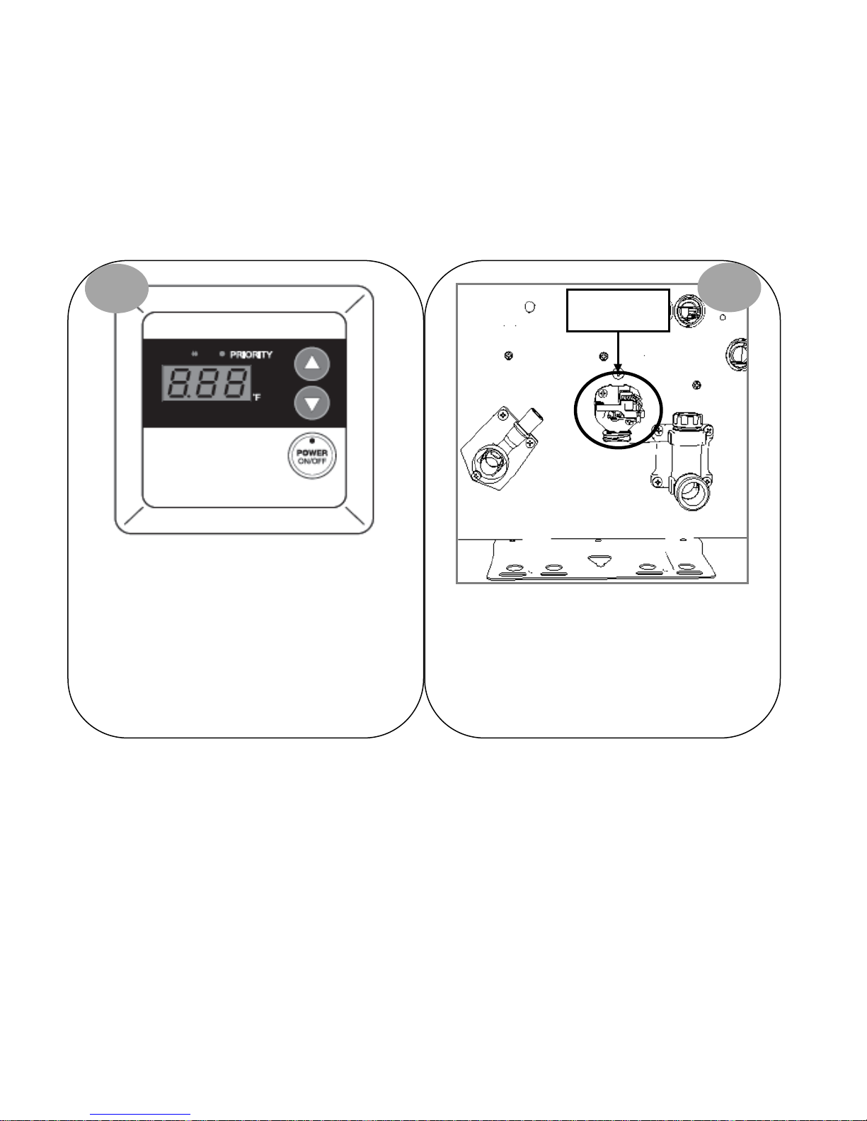
84 | Page SVC 820 Tankless Gas Trouble Shooting Manual
84
76 – Error Code
Explanation: Communication Fault with Remote Control.
Remote Control is not communicating with Control Board
REMOTE THERMOSTAT DIAGNOSTICS:
1
Visually inspect Remote Control wiring for damaged or
loose terminals.
Diagnostic Checks:
• Remote Control
• Wiring
2
Remote Control
Wiring Terminals
Hot Water Outlet
Cold Water Inlet
Turn power OFF. Remove and reconnect Remote Control
wiring terminals at bottom of unit. Attempt to operate
unit again. IF 76 Error Code does NOT display, unit had a
loose connection.
IF 76 Error Code IS displayed, continue to diagnostic chart
on next page.
Page 85
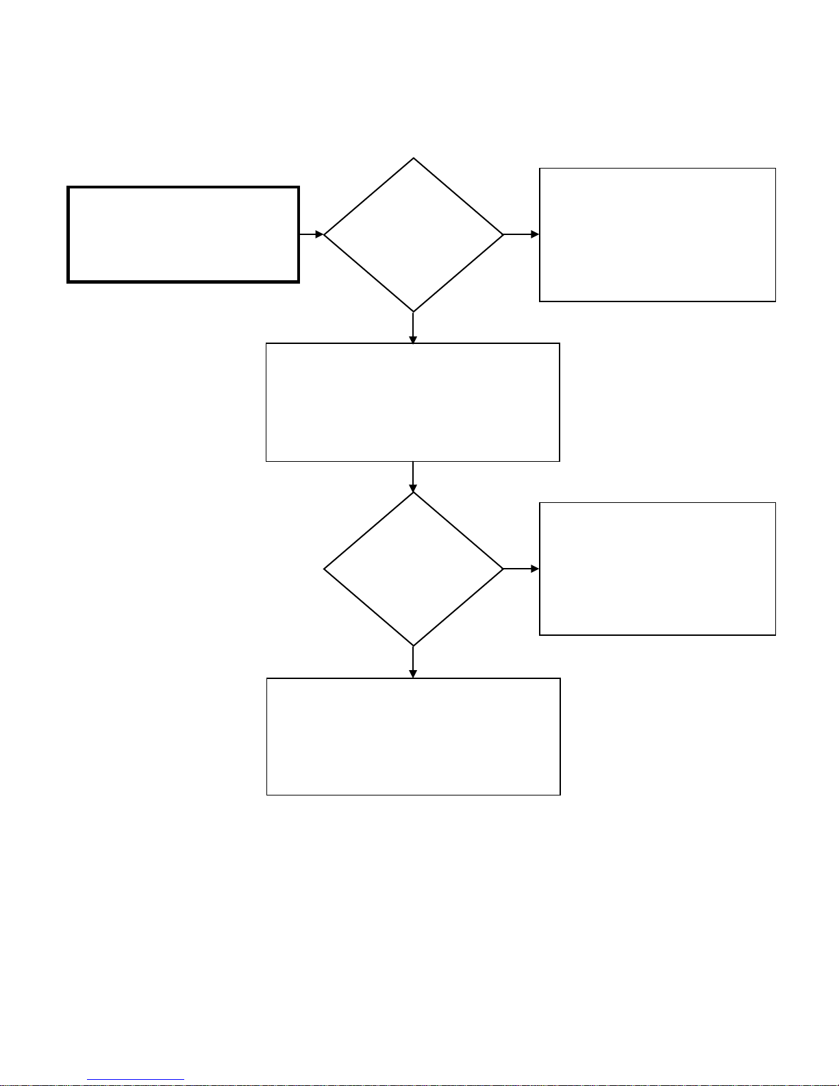
SVC 820-Tankless Gas Trouble Shooting Manual Page | 85
85
Did the unit go to
Did the unit go to
76 – Error Code Diagnostic Chart
Unplug unit and remove Remote
Thermostat wires from wiring terminals
on bottom of unit. Plug unit in and open
a hot water source.
main burner?
YES
Unplug unit. Use a short piece of new thermostat
wire to connect the Remote Control directly to
Remote Control wiring terminals at bottom of unit.
Plug unit in and open a hot water source.
main burner?
NO
NO
Attempt to operate unit again. If the unit
malfunctions due to an Error Code 76:
Replace Remote Control
Replace Remote Control
YES
The wiring is defective. Replace Remote Control
wiring.
Page 86
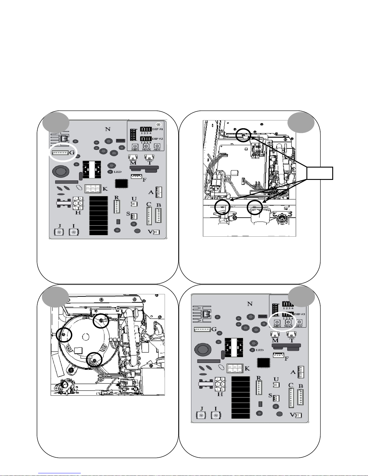
86 | Page SVC 820 Tankless Gas Trouble Shooting Manual
86
79 – Error Code
Explanation: Blower Motor current fault. The unit
detected a fault with the Blower Motor.
Diagnostic Checks:
• Blower Motor
BLOWER MOTOR DIAGNOSTICS:
1 2
Control Board
Bottom of Unit
Screws
Turn power OFF. Remove and reinsert connector “G”
on Control Board. Attempt to operate unit again. IF
79 Error Code does NOT display, unit had a loose
connection.
3
Blower Motor
Remove 3 screws holding Blower Motor in place.
Clean Blower Motor and reassemble unit. Attempt to
operate unit again. IF 79 Error Code does NOT
display: Blower Motor needed to be cleaned.
Turn power OFF. Remove 3 screws for Control Board
mounting bracket. Remove connectors “M”, “T” &
“G”. Pull Control Board out of way to access Blower
Motor.
4
Locate Min & Max buttons on Control Board.
Continue to diagnostic chart on next page.
Page 87
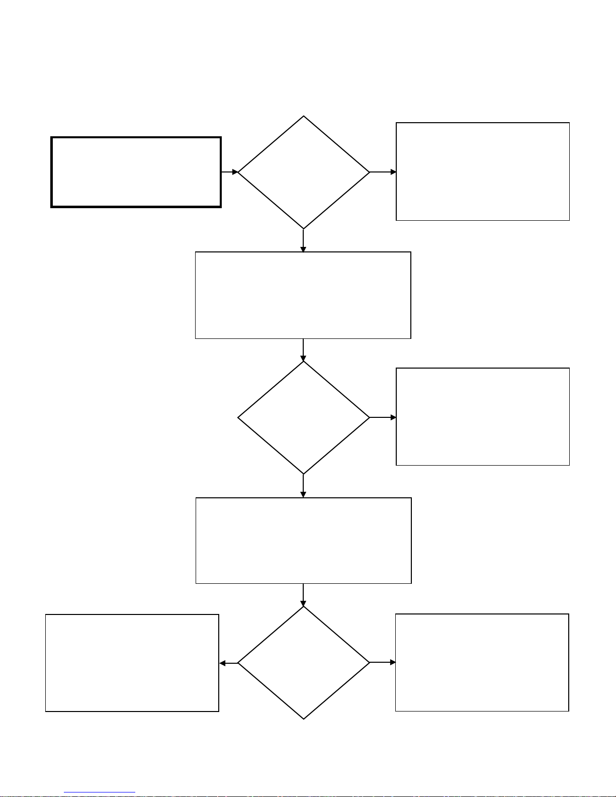
SVC 820-Tankless Gas Trouble Shooting Manual Page | 87
87
Remove and reinsert connector “G”.
Attempt to operate unit again.
18 DC VOLTS
Attempt to operate unit again.
79 – Error Code Diagnostic Chart
Test DC voltage across black and red
wires on Molex connector “G”:
144 – 192 DC VOLTS
Press and hold down “MAX” button on Control Board
test DC voltage across black and white wires on Molex
to activate Blower Motor. While Blower is running,
Is the DC voltage
OK?
YES
connector “G”:
12 –
NO
IF the unit malfunctions due to an Error
Code 79:
Replace Control Board
Attempt to operate unit again.
If the unit malfunctions due to an Error
Code 79:
Is the DC voltage
OK?
YES
Press and hold down “MAX” button on Control Board
to activate Blower Motor. While Blower is running,
test DC voltage across black and blue wires on Molex
connector “G”:
4 – 10 DC VOLTS
Is the DC voltage
YES NO
OK?
NO
Remove and reinsert connector “G”.
If the unit malfunctions due to an Error
Code 79:
Replace Control Board
Replace Blower Motor
Replace Control Board
Page 88
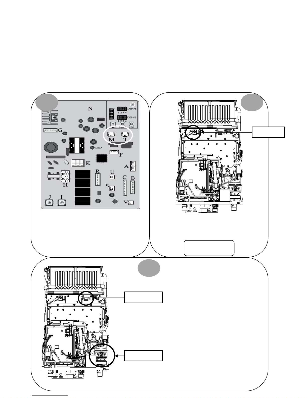
88 | Page SVC 820 Tankless Gas Trouble Shooting Manual
88
Remove and reinsert terminals on Flame Rod(s)*.
80 – Error Code
Explanation: Gas Control Valve malfunction. The unit
detects the presence of flame when the demand for hot
water is terminated and burner is OFF. This error code will
only occur at time of shut down.
Diagnostic Checks:
• Flame Rod(s)
• Gas Control Valve
FLAME ROD(s) & GAS CONTROL VALVE DIAGNOSTICS:
1 2
Flame Rod(s)*
Turn power OFF. Remove and reinsert white
connector “M” and blue connector “T” on Control
Board.
3
Sight Glass
Attempt to operate unit again. IF 80 Error Code does
NOT display, unit had a loose connection.
*Indoor Units ONLY:
Visually inspect Gas Control Valve wiring
harnesses for loose connection or
damaged wiring. Gas Control Valve is
located on lower right side of unit. Locate
2 Flame Rods
Sight Glass.
Gas Control Valve
Page 89
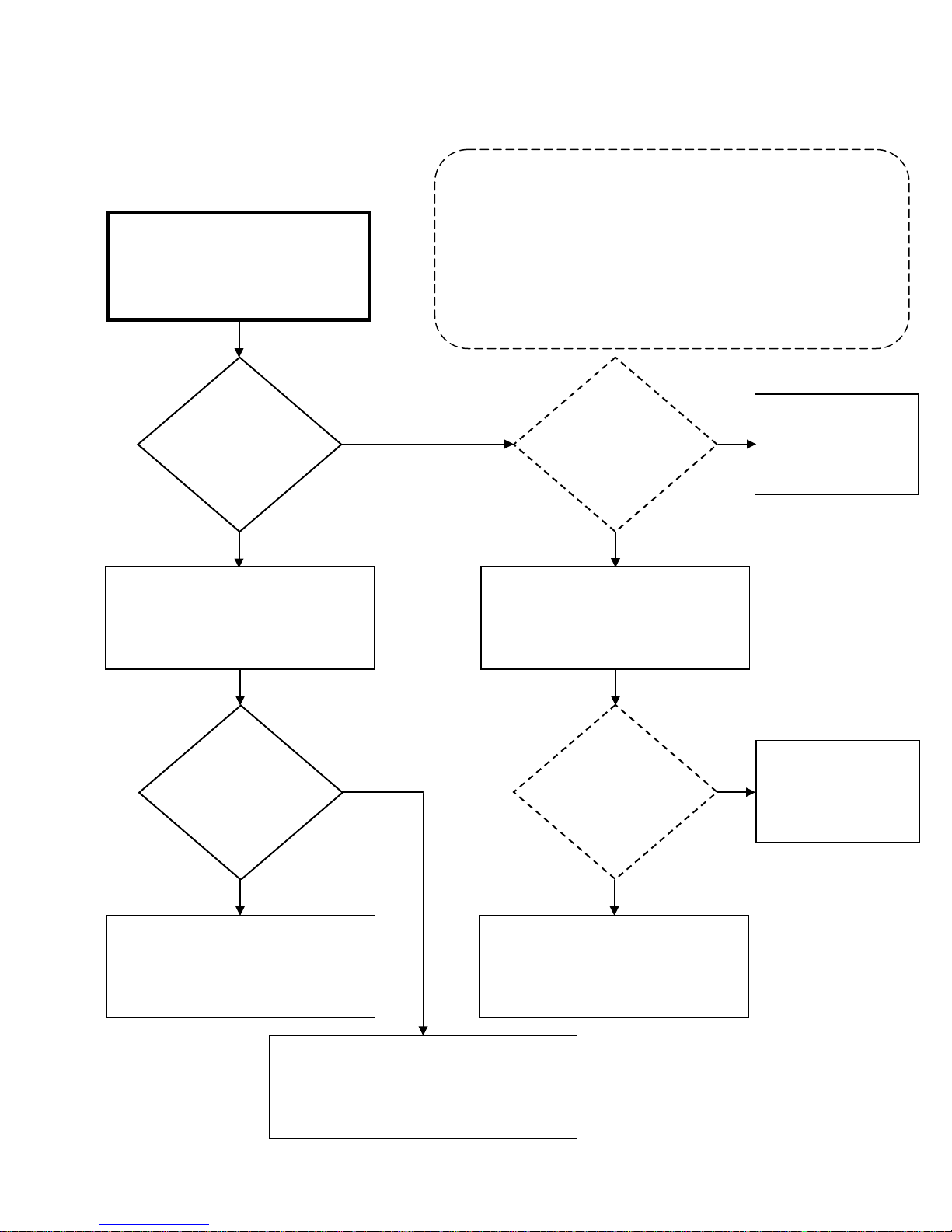
SVC 820-Tankless Gas Trouble Shooting Manual Page | 89
89
to be normal.
While viewing burner chamber through
sight glass:
heater 3 times by turning unit
“on – off; on – off; on – off”
Is debris visible
ode
ode
Attempt to operate unit again.
Indoor Units: 05
80 – Error Code Diagnostic Chart
In 10 second intervals; cycle the water
Visibly inspect burner chamber through
Is there a visible
flame while unit
is OFF?
YES
sight glass
On Remote Control, go to Maintenance Mode 0Y table. For Maintenance
Mode instructions go to page16.
All Maintenance Mode ‘0Y’ readings should be done immediately after
turning the unit OFF. IF Flame Rod(s) is detecting flame, Maintenance Mode
will display:
Outdoor Units: 01
NO
Does ‘OY’ Status in
Maintenance M
indicate presence
of flame after 5
seconds?
YES
Disconnect Molex Connector from Flame
Rod(s). Cycle heater 3 times by turning
unit “on – off”; “on – off”; “on – off”
NO
Water heater appears
Attempt to operate
again
on burner
assembly?
YES
Remove and clean burner assembly
Attempt to operate again. If unit displays 80
Error Code and flame IS visible while unit is OFF:
NO
Replace Gas Control Valve
Does ‘OY’ Status in
Maintenance M
indicate presence
of flame after 5
seconds?
YES
If unit displays 80 Error Code:
Replace Control Board
NO
Clean or Replace Flame
Rod(s)
Page 90
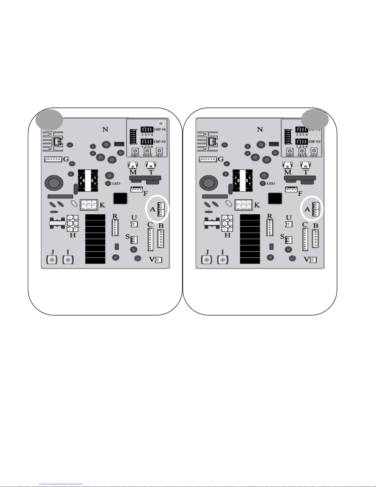
90 | Page SVC 820 Tankless Gas Trouble Shooting Manual
90
unit again.
82 – Error Code
Explanation: Control Board Program Chip malfunction
PROGRAM CHIP DIAGNOSTICS:
1
Diagnostic Checks:
• Program Chip
2
Turn power OFF. Verify you have a Program Chip inserted
in connector “A”.
Remove and reinsert Program Chip. Attempt to operate
IF unit does NOT display 82 Error Code, unit had a loose
connection.
Page 91

SVC 820-Tankless Gas Trouble Shooting Manual Page | 91
91
90 – Error Code
Explanation: The unit detected blockage in the venting during pre-purge cycle. This Error Code will occur BEFORE unit goes to
ignition.
Possible Causes:
• VENTING
VENTING:
Visually inspect venting for possible blockage and/or recirculation of exhaust.
1. Approved Venting Materials
2. Approved Vent Terminations
3. Vent Lengths
4. Location Of Vent Termination (Recirculation of exhaust)
5. Blocked Venting
6. Venting Not Sealed Properly
**REFER TO USE & CARE MANUAL**
Page 92
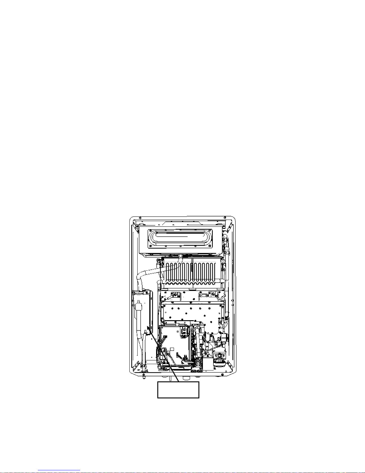
92 | Page SVC 820 Tankless Gas Trouble Shooting Manual
92
92 – Error Code
Explanation: High Efficiency Condensing Units ONLY. This is a warning code and unit will continue to
operate but will eventually shut down due to an error code 93. REPLACE NEUTRALIZER ASAP.
*
Once Neutralizer is replaced; follow reset procedures on page 21.
93 – Error Code
Explanation: High Efficiency Condensing Units ONLY. Unit will NOT operate until the Neutralizer
Medium is replaced. REPLACE NEUTRALIZER IMMEDIATELY.
Neutralizer rocks made from Calcium Carbonate (CACO
Neutralizer Kit may be ordered through Rheem Supplier.
*
Once Neutralizer is replaced; follow reset procedures on page 21.
3).
Neutralizer
Page 93

SVC 820-Tankless Gas Trouble Shooting Manual Page | 93
93
6. Venting Not Sealed Properly
99 – Error Code
Explanation: The unit detected blockage in the venting during post-purge cycle. Blockage was detected when the demand for
hot water terminated and burner was OFF. This error code will only occur at time of shut down.
*Unit must be reset by performing reset procedure on page 21.
Possible Causes:
• Venting
**REFER TO USE & CARE MANUAL**
VENTING:
Visually inspect venting for possible blockage and/or recirculation of exhaust.
1. Approved Venting Materials
2. Approved Vent Terminations
3. Vent Lengths
4. Location Of Vent Termination (Recirculation of exhaust)
5. Blocked Venting
Page 94

94 | Page SVC 820 Tankless Gas Trouble Shooting Manual
94
NOTES:
______________________________________________
______________________________________________
______________________________________________
______________________________________________
______________________________________________
______________________________________________
______________________________________________
______________________________________________
______________________________________________
______________________________________________
______________________________________________
______________________________________________
______________________________________________
______________________________________________
______________________________________________
______________________________________________
______________________________________________
______________________________________________
______________________________________________
______________________________________________
Page 95

SVC 820-Tankless Gas Trouble Shooting Manual Page | 95
95
NOTES:
______________________________________________
______________________________________________
______________________________________________
______________________________________________
______________________________________________
______________________________________________
______________________________________________
______________________________________________
______________________________________________
______________________________________________
______________________________________________
______________________________________________
______________________________________________
______________________________________________
______________________________________________
______________________________________________
______________________________________________
______________________________________________
______________________________________________
______________________________________________
Page 96

R
Tankless Gas Water Heaters
High Effi ciency Condensing Models
PHH-25ROFN & PHH-32ROFN (Outdoor Natural Gas Models)
PHH-25ROFP & PHH-32ROFP (Outdoor L.P. Gas Models)
PHH-25RDVN & PHH-32RDVN (Indoor Direct Vent Natural Gas Models)
PHH-25RDVP & PHH-32RDVP (Indoor Direct Vent L.P. Gas Models)
Mid Effi ciency Models
PH2-20ROFN, PH2-25ROFN & PH2-28ROFN (Outdoor Natural Gas Models
PH2-20ROFP, PH2-25ROFP & PH2-28ROFP (Outdoor L.P. Gas Models)
PH2-20RDVSN, PH2-25RDVSN & PH2-28RDVSN
(Indoor Direct Vent Natural Gas Models)
PH2-20RDVSP, PH2-25RDVSP & PH2-28RDVSP
(Indoor Direct Vent L.P. Gas Models)
Second Section
Information Guide
- 96 -
Page 97
- Do not store or use gasoline or other flammable vapors and liquids in the
vicinity of this or any other appliance. To do so may result in an explosion or fire.
- WHAT TO DO IF YOU SMELL GAS
* Do not try to light any appliance.
* Do not touch any electrical switch; do not use any phone in your building.
* Immediately call your gas supplier from a neighbor's phone. Follow the gas
supplier's instructions.
* If you cannot reach your gas supplier, call the fire department.
* Do not return to your home until authorized by the gas supplier or fire department.
- Installation and service must be performed by a qualified installer, service
agency or the gas supplier.
WARNING: If the information in these instructions is not followed
exactly, a fire or explosion may result causing property damage,
personal injury or death.
WARNING: Improper installation, adjustment, alternation, service or maintenance
can cause property damage, personal injury, or death. For assistance or additional
information, consult with a qualifi ed distributor.
WARNING: The content on this manual is intended for use by qualifi ed service
personnel ONLY.
Table of Contents for Second Section
- 97 -
Page
Specifi cations .................................................................. 98 ~ 99
External Dimensions ...................................................... 100 ~ 101
Schematic Construction ................................................. 102 ~ 105
Operational Principle ..................................................... 106 ~ 111
Capacity ......................................................................... 112 ~ 120
Wiring Diagram ............................................................. 121 ~ 122
Thermistor Resistance Chart .......................................... 123
Adjustment ..................................................................... 124 ~ 132
DUOnex Cable ............................................................... 133 ~ 136
MIC-185 ......................................................................... 137 ~ 146
MIC-6 ............................................................................. 147 ~ 154
Commercial Conversion ................................................ 155 ~ 157
Schematic Disassembly and Parts List .......................... 158 ~ 171
Page 98
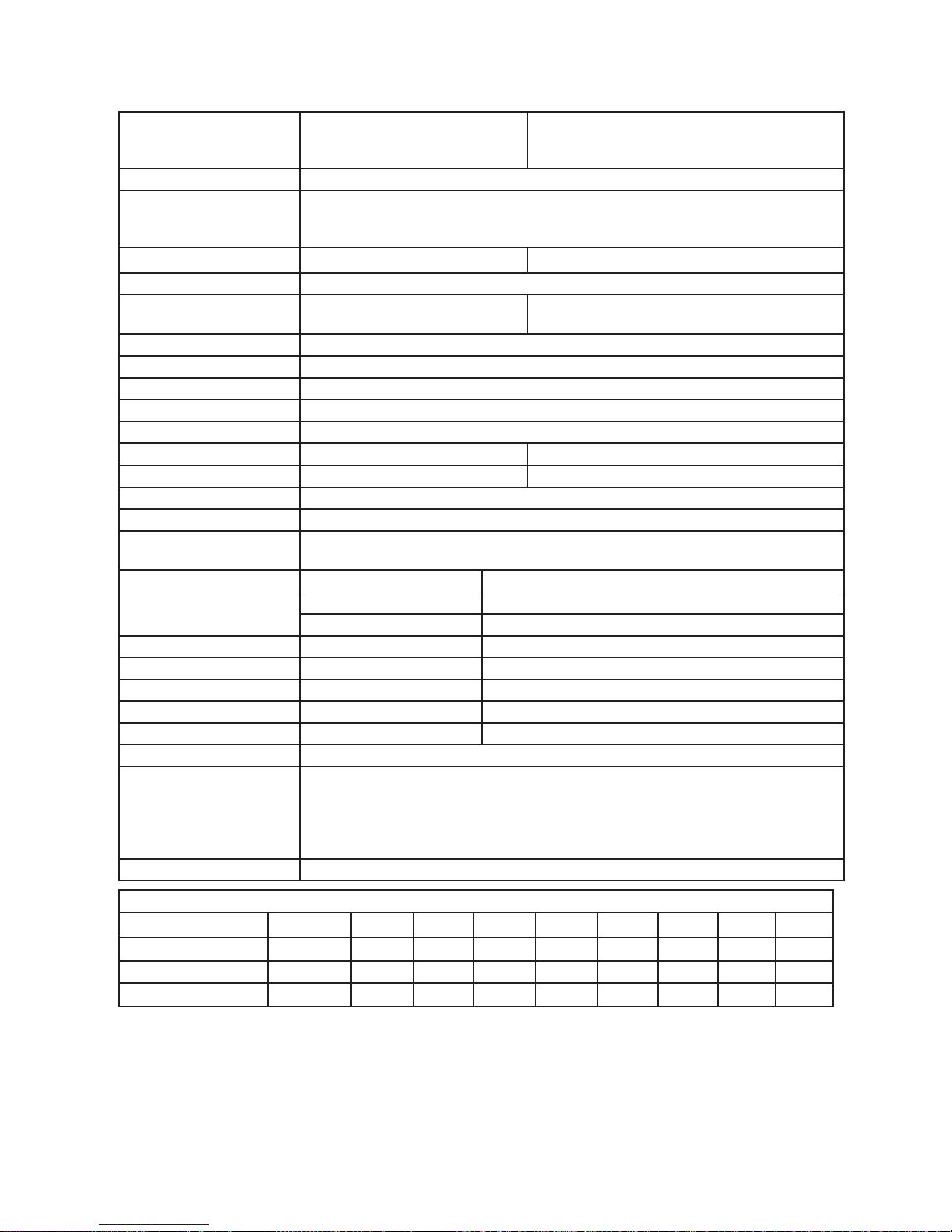
SPECIFICATIONS (Approx.)
Model PH2-20R OFN, PH2-20R OFP,
PH2-25R OFN, PH2-25R OFP
PH2-28R OFN, PH2-28R OFP
PH2-20R DVSN, PH2-20R DVSP
PH2-25R DVSN, PH2-25R DVSP
PH2-28R DVSN, PH2-28R DVSP
Purpose Domestic Hot Water Supply
Rated Gas Input
(Btu/Hr.)
11,000 (Min.) ~ 150,000 (Max.) (PH2-20R Series) Modulating
11,000 (Min.) ~ 180,000 (Max.) (PH2-25R Series) Modulating
11,000 (Min.) ~ 199,900 (Max.) (PH2-28R Series) Modulating
Dimensions (in.) 13 7/8 (W) x 23 5/8 (H) x 8 7/8 (D) 13 7/8 (W) x 25 5/8 (H) x 9 7/8 (D)
Net Weight (lbs.) 60
Installation Outdoor W all Mounting Type Direct Vent Indoor Wall Mounting Type
Can be vented either horizontally or vertically
Working Water Pressure 14 psi ~ 150 psi
Minimum Water Flow 0.40 GPM
Maximum Flow Rate 6.4 GPM (PH2-20R); 8.4 GPM (PH2-25R); 9.5 GPM (PH2-28R) at 35ºF Temp. Rise
Gas Connection 3/4” NPT Female (w/supplied Gas Shutoff Valve)
Water Connection 3/4” NPT Male
Vent Size N/A (Outdoor Installation) 3”/5” Concentric Special Venting (Category III)
Max. Vent Length N/A (Outdoor Installation) 36 Feet with Three 90º Elbow
Effi ciency Rating 84%
Energy Factor 0.82
Inlet Gas Pressure
before water heater
Natural Gas: Min. 4.0” w.c. Max. 10.5” w.c.
L.P. Gas: Min. 8.0” w.c. Max. 13.0” w.c. (Do not exceed maximum pressure.)
Hot Water Supply Adjusting Range 85ºF ~ 120ºF (140ºF) (Residential)
Adjusting Range 85ºF ~ 185ºF (Commercial) (By conversion kit)
Max. Setting W/ Main Remote Control (UMC-117) & Adjustment
Electrical Portion Electrical Rating 120VAC/60Hz, Less than 2 Amps
Power Supply Cord 3 Pin Power Supply Cord 10 Feet (Direct Vent)
Safety Devices Oxygen Depletion Safety Sensing Burner (Direct Vent)
Over Heat Limiter Film Type for Entire Heat Exchanger
Flame Failure Safety Flame Rod Type
Freeze Protection Minus 30ºF (Without Wind-Chill Factor)
Optional Accessory First Bath Remote Control (USC1-117); Second Bath Remote Control (USC2-117)
DUOnex ™ for 2-Unit Manifolding
MIC-185 for Multi-Unit System Controller (2 to 6 units); MICS-180 for Expansion Board
(Up to 20 units); Communication Cables for MIC-185 (16, 32 & 65 feet)
MIC-6 for Manifold Controller (2 to 6 units); Manifold Cables for MIC-6 (6 & 18 feet)
High Altitude Setting High Altitude DIP Switch Adjustment
Hot Water Flow Rate and Temperature Rise
Temp. Rise (ºF)
35
45 50 60 70 80 90 100
Water Flow (GPM) PH2-20R 6.4 5.6 5.1 4.2 3.6 3.2 2.8 2.5
Water Flow (GPM) PH2-25R 8.4 6.7 6.1 5.1 4.3 3.8 3.4 3.0
Water Flow (GPM) PH2-28R 9.5 7.4 6.6 5.5 4.7 4.1 3.7 3.3
- 98 -
Note: Special Venting: The adapter, vent pipe, elbow, vent terminal, etc. should be UL 1738 Certifi ed Category III Stainless
Steel Venting Materials . “B” vent is not permitted.
Since we are constantly improving our products, all specifi cations are subject to change without notice.
Page 99
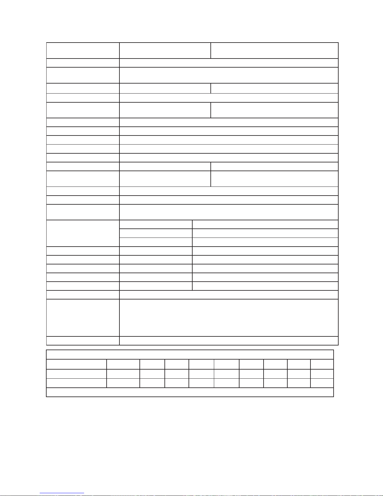
SPECIFICATIONS (Approx.)
Model PHH-25ROFN, PHH-25ROFP
PHH-32ROFN, PHH-32ROFP
PHH-25RDVN, PHH-25RDVP
PHH-32RDVN, PHH-32RDVP
Purpose Domestic Hot Water Supply
Rated Gas Input
(Btu/Hr.)
11,000 (Min.) ~ 157,000 (Max.) (PHH-25R Series) Modulating
11,000 (Min.) ~ 199,900 (Max.) (PHH-32R Series) Modulating
Dimensions (in.) 18 1/2 (W) x 27 5/8 (H) x 9 3/4 (D) 18 1/2 (W) x 30 3/8 (H) x 9 3/4 (D)
Net Weight (lbs.) 76
Installation Outdoor W all Mounting Type Direct Vent Indoor Wall Mounting Type
Can be vented either horizontally or vertically
Working Water Pressure 14 psi ~ 150 psi
Minimum Water Flow 0.40 GPM
Maximum Flow Rate 8.5 GPM (PHH-25R); 9.5 GPM (PHH-32R) at 35ºF Temp. Rise
Gas Connection 3/4” NPT Female (w/supplied Gas Shutoff Valve)
Water Connection 3/4” NPT Male
Vent Size N/A (Outdoor Installation) 2” or 3” PVC or CPVC
Max. Vent Length N/A (Outdoor Installation) 35 Feet with Three 90º Elbow (3” PVC)
5 Feet with One 90º Elbow (2” PVC)
Effi ciency Rating 93% (PHH-25ROF, PHH-32ROF, PHH-32RDV); 94% (PHH-25RDV)
Energy Factor 0.93 (PHH-25ROF); 0.94 (PHH-25RDV, PHH-32ROF, PHH-32RDV)
Inlet Gas Pressure
before water heater
Natural Gas: Min. 4.0” w.c. Max. 10.5” w.c.
L.P. Gas: Min. 8.0” w.c. Max. 13.0” w.c. (Do not exceed maximum pressure.)
Hot Water Supply Adjusting Range 85ºF ~ 120ºF (140ºF) (Residential)
Adjusting Range 85ºF ~ 185ºF (Commercial) (By conversion kit)
Max. Setting W/ Main Remote Control (UMC-117) & Adjustment
Electrical Portion Electrical Rating 120VAC/60Hz, Less than 2 Amps
Power Supply Cord 3 Pin Power Supply Cord 10 Feet (Direct Vent)
Safety Devices Oxygen Depletion Safety Flame Rod (Direct Vent)
Over Heat Limiter Film Type for Entire Heat Exchanger
Flame Failure Safety Flame Rod Type
Freeze Protection Minus 30ºF (Without Wind-Chill Factor)
Optional Accessory First Bath Remote Control (USC1-117); Second Bath Remote Control (USC2-117)
DUOnex ™ for 2-Unit Manifolding
MIC-185 for Multi-Unit System Controller (2 to 6 units); MICS-180 for Expansion Board
(Up to 20 units); Communication Cables for MIC-185 (16, 32 & 65 feet)
MIC-6 for Manifold Controller (2 to 6 units); Manifold Cables for MIC-6 (6 & 18 feet)
High Altitude Setting High Altitude DIP Switch Adjustment
Hot Water Flow Rate and Temperature Rise
Temp. Rise (ºF)
35
45 50 60 70 80 90 100
Water Flow (GPM) PHH-25R 8.5 6.6 5.9 4.9 4.2 3.7 3.3 3.0
Water Flow (GPM) PHH-32R 9.5 8.4 7.6 6.3 5.4 4.7 4.2 3.8
- 99 -
Note: Venting: Schedule 40 (PVC), Schedule 40 (CPVC) or Category III Stainless Steel . “B” vent is not permitted.
Since we are constantly improving our products, all specifi cations are subject to change without notice.
Page 100
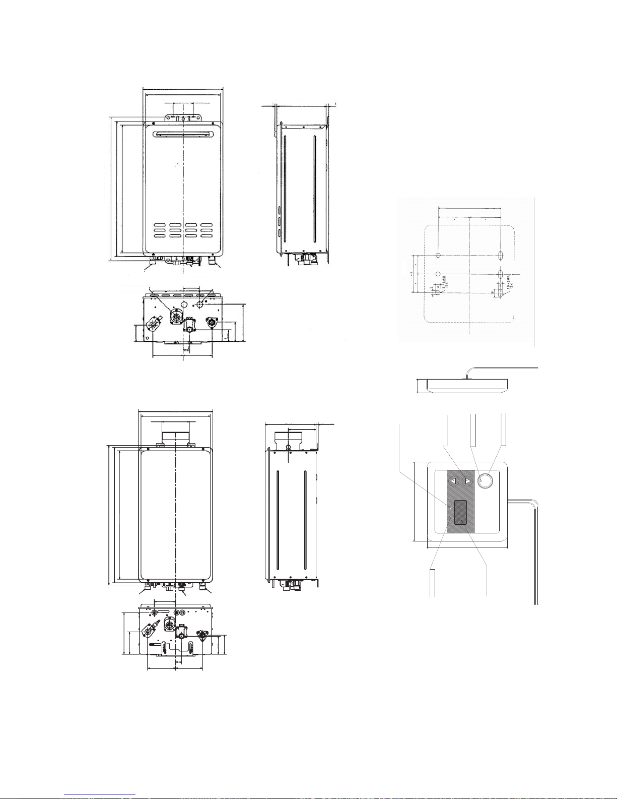
EXTERNAL DIMENSIONS
(Remote Control)
COMBUSTION
INDICATOR
POWER ON/OFF
INDICATOR
POWER ON/OFF
BUTTON
PRIORITY INDICATOR
TEMPERATURE
ADJUSTMENT
BUTTON
LED DISPLAY
POWER
ON/OFF
PRIORITY
°
F
7/8” (21mm)
4 3/4” (120mm)
4 3/4” (120mm)
1 7/8” 46mm)
3 1/4” (83.5mm)
13 7/8” (350 mm)
12 15/16” (328 mm)
3 1/2” (90 mm)
25 3/16” (640 mm)
23 5/8” (600 mm)
22 3/8” (568 mm)
2 7/8” (72.5 mm)
2 15/16” (73 mm)
5 3/16” (132 mm)
1 1/8” (28 mm)
5” (127 mm)
2 1/16” (53 mm)
2 1/4” (58 mm)
5 1/4” (134 mm)
7/16” (10.5 mm)
8 7/16” (215 mm)
3/8”
(10 mm)
Hot Water Outlet
Connection 3/4” NPT (M)
Water Inlet Connection
3/4” NPT (M)
Gas Connection 3/4” NPT (F)
(W/Supplied Gas Shutoff Valve)
For Power Cord
For Remote Control
Connection
(PH2-20ROF, PH2-25ROF & PH2-28ROF Outdoor Models)
13 7/8” (350 mm)
12 15/16” (328 mm)
5 1/8” (130 mm)
3”/5” Concentric
9 7/16” (240 mm)
5 1/8” (131 mm)
3/8” ~ 1 9/16”
(10 ~ 40 mm)
Hot Water Outlet
Connection 3/4” NPT (M)
Water Inlet Connection
3/4” NPT (M)
Gas Connection 3/4” NPT (F)
(W/Supplied Gas Shutoff Valve)
3” (100.5 mm)
5 3/16” (132 mm) 5” (127 mm)
1 1/8” (28 mm)
7 7/8” (200 mm)
4 3/16” (107 mm)
3 3/8” (86 mm)
3 5/8” (92 mm)
26 7/16” (672 mm)
25 5/8” (650 mm)
24 3/8” (618 mm)
(PH2-20RDVS, PH2-25RDVS &
PH2-28RDVS Direct Vent Models)
- 100 -
 Loading...