

Paloma MIC-180 User Manual

Manifold Installation Controller
MIC-180
Installation and Operation Instructions
For Use With
Rheem-Ruud and Paloma Commercial Tankless
Water Heaters
Table of Contents
Safety Information............................................................ 1-2
Manifold Installation Control System............................... 3
Installing the Manifold Controller .................................... 4
Mounting the Manifold Controller.................................... 4
Electrical Connections ..................................................... 4-5
Connecting Communication Cable to the Water Heaters.. 6-7
Connecting and Wiring the Manifold Controller .............. 7-8
Setting Hot Water Temperature......................................... 9
Typical Installation of Extended Manifold Controller ...... 10-11
Trial Operation of Manifold Installation Controller.......... 12
If You Need Service .......................................................... 12
SAFETY PRECAUTIONS
• Read these instructions and the water heater instruction manual entirely before installing
or operating the manifold controller and the water heater.
• Use this manifold controller only for its intended purpose as described in these
instructions.
• Be sure your water heater and the manifold controller are properly installed in accordance
with local codes and the provided installation instructions.
• Do not attempt to repair or replace any parts. All servicing should be referred to a
qualified technician.
• Read and follow all instructions. Save this instruction for future reference.
Printed in Japan AP13756 (04/05) 31-52481
- 1 -
IMPORTANT SAFETY INFORMATION
READ ALL INSTRUCTIONS BEFORE USING
WARNING:
For your safety, the information in these instructions and the instructions provided with the
water heater must be followed to minimize the risk of fire or explosion, electric shock, or to
prevent property damage, personal injury, or loss of life.
Improper adjustment, alteration, service or maintenance can cause property damage, personal
injury or death. Only qualified service personnel should install or make adjustments.
DANGER:
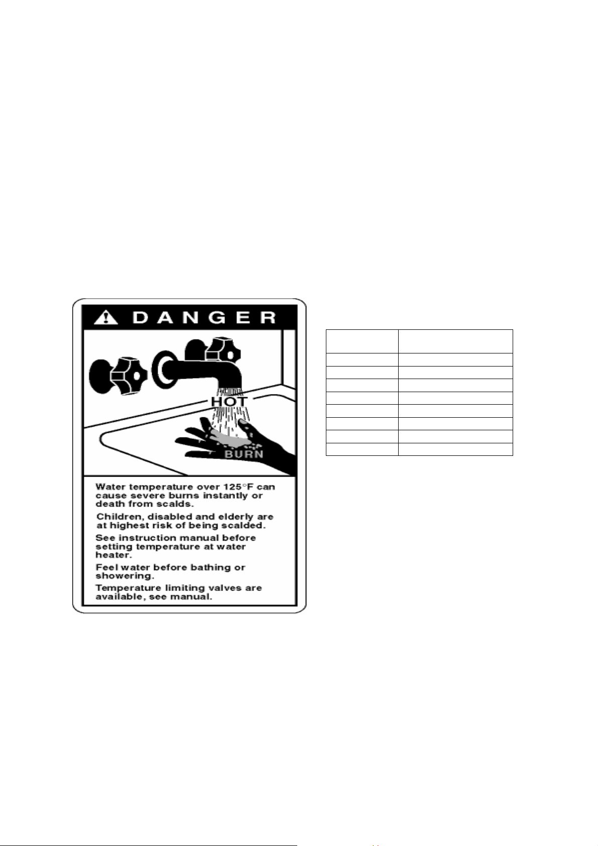
WATER TE MPERATURE SETTING
Safety and energy conservation are factors to be considered when selecting the water
temperature setting of a water heater. Water temperatures above 125°F (52°C) can cause severe
burns or death from scalding. Be sure to read and follow the warning outlined in the label
pictured below.
TIME/TEMPERATURE RELATIONSHIP IN
SCALDS
Temperature Time to Produce Serious Burn
120°F (49°C)
125°F (52°C)
130°F (54°C)
135°F (57°C)
140°F (60°C)
145°F (63°C)
150°F (66°C)
155°F (68°C)
Table courtesy of Shrines Burn Institute
More than 5 minutes
11/2 to 2 minutes
About 30 seconds
About 10 seconds
Less than 5 seconds
Less than 3 seconds
About 11/2 seconds
About 1 second
The time/temperature relationship table shown above may be used as a guide in determining the proper
water temperature for your home or any other application.
A thermostatically controlled mixing valve for reducing point of use water temperature is
recommended to reduce the risk of scald injury. Contact a licensed plumber or local plumbing
authority for further information.
DANGER: Households with small children, disabled, or elderly persons may require a 120°F
(49°C) or lower temperature setting to prevent contact with “Hot” water.
TIME/TEMPERATURE REALTIONSHIP IN
SCALDS
Temperature Time to Produce Serious
Burn
120°F (49°C)
125°F (52°C)
130°F (54°C)
135°F (57°C)
140°F (60°C)
145°F (63°C)
150°F (66°C)
155°F (68°C)
More than 5 minutes
½ to 2 minutes
1
About 30 seconds
About 10 seconds
Less than 5 seconds
Less than 3 seconds
About 1½ seconds
About 1 second
Danger: Hotter water increases the risk of
hot water scalds.
- 2 -
1. Manifold Installation Control System (MIC-180)
The manifold installation control system (MIC-180)
manifolding two (2) to six (6) water heaters, mounting screws, manifold box, power supply cord, and
connector for optional hardwiring.
Manifold controller (MIC-180) provides control of two (2) to six (6) water heaters when properly
installed and connected with communication cables (sold separately) to any Rheem-Ruud or Paloma
commercial Tankless Water Heaters. To control additional water heaters (7 to 20 water heaters), it is
necessary to purchase an extended communication PCB (MICS-180) separately and install in the
control system. See section 6, “Typical Installation of Extended Manifold Controller” on page 10 for
instructions on installing extended communications PCB.
This instruction sheet outlines the configuration and in stallation for manifolding two (2) to twenty (20)
water heaters.
NOTICE:
No other manufacturer’s controls are suitable with Rheem-Ruud or Paloma Commercial
Tankless Wate r Heaters. Do not attempt to disassemble any of the controls or comp onents.
consists of a main communication PCB for
1-1. Optional Parts
• Extended communication PCB (MICS-180) for manifold control of seven (7) to twenty (20)
water heaters
• Communication cable (available in 16 ft (4.87 m), 32 ft (9.75 m), and 65 ft (19.81 m) length)
Components
Manifold controller (Basic Unit) - MIC-180 1 1
Extended communication PCB - MICS-180
Communication cable (16 feet) - MIC-K-16* 2 ~ 6 7 ~ 20
Communication cable (32 feet) - MIC-K-32* 2 ~ 6 7 ~ 20
Communication cable (65 feet) - MIC-K-65* 2 ~ 6 7 ~ 20
+
Extended communication PCB (MICS-180) includes one relay cable and one screw.
* Communication cables include two clamps and two screws.
+
Not applicable 1
Number of Water Heaters
2 ~ 6 Units 7 ~ 20 Units
1-2. Typical Manifold Installation
- 3 -
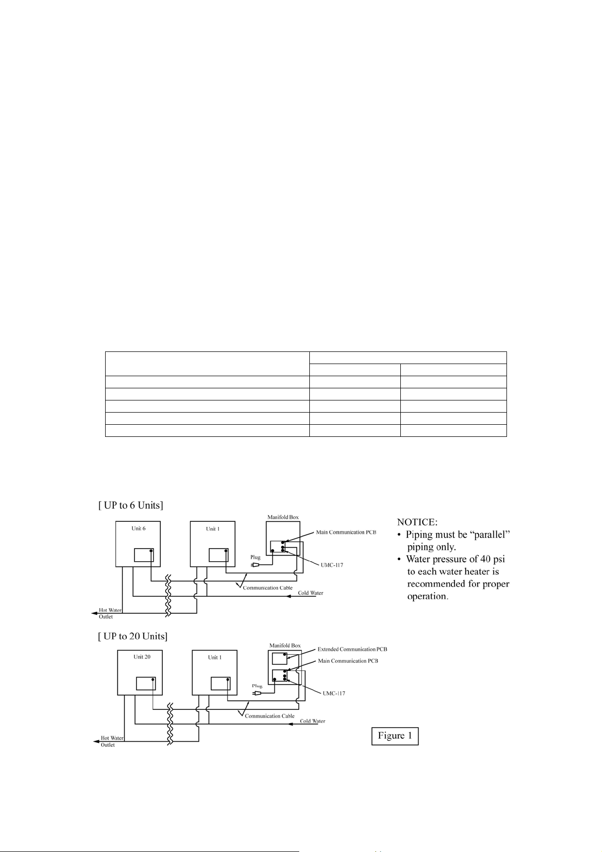
See figure 1 for typical installations of a manifold controller and extended communication PCB with
multiple water heaters. An extended communication PCB is required for installation of more than six
(6) water heaters. The extended communication PCB and the communication cables are sold
separately.
NOTICE:
Install the water heater, water piping, and gas piping per installation instructions provided with
the water heaters. A shutoff valve should be installed at the inlet water pipe, outlet water pipe
and gas inlet line of each water heater to facilitate easy service.
2. Installing the Manifold Controller
NOTICE: Follow instructions provided with the water heater for installing the water heater and
main remote control. The main remote control is provided with the water heater.
Location
The manifold controller (MIC-180) can be installed indoors or outdoors. The main remote control
(UMC-117) must be installed indoors and per instructions provided with the water heater.
2-1. Mounting the Manifold Controller
Make sure the location of the manifold controller allows easy access for service and operation.
Wall studs should be utilized when mounting the manifold controller to the wall. Alternately, a suitable
piece of wood may be placed inside or outside of the wall to span the distance between the wall studs.
Fasten the water heater mounting brackets to the wood. In case of dry wall or concrete wall use dry
wall anchors or lag bolts.
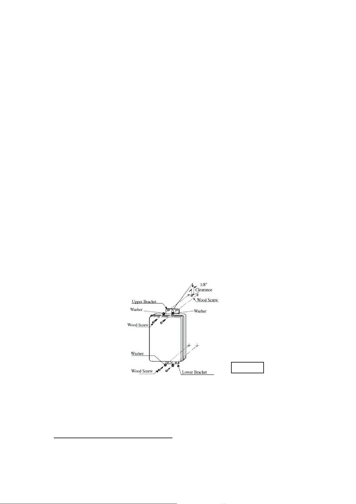
Install a wood screw for the upper bracket with a clearance of 1/8” (3 mm) between the wall and the
screw head. Hang the center of the upper bracket on the screw. Using a wood screw and washer, affix
the lower bracket to the wall (Left and right). Repeat to affix the top bracket. See figure 2 shown
below for typical mounting of the manifold controller.
The manifold controller requires 120VAC/60Hz. Have a receptacle with the ground terminal near the
manifold controller. The length of the power supply cord is 10 feet (3.05 m). If local codes require, or
if installed outdoors, the manifold controller should be hard wired.
Figure 2
2-2. Electrical Connections
WARNING: Field wiring connections and electrical grounding must comply with local codes, or
in the absence of local codes, with the latest edition of the National Electrical Code,
ANSI/NFPA 70, or in Canada, Canadian Electrical code, CSA C22.1 Part 1.
POWER CORD (INDOOR Installation Only):
• The electrical power supply requirement for this manifold controller is 120VAC/60Hz, 3
Amps.
• The manifold controller comes with a three (3) pin power supply cord.
- 4 -
 Loading...