

Paloma DUOnex 2-Unit System User Manual
Tankless Water Heater DUOnex™ 2-Unit System
ON
1
2
3
4
DIP1
ONOFF
1
2
3
4
SW1 SW2
SW3
ON
1
2
3
4
DIP1
ONOFF
1
2
3
4
R
Installation Instructions
The DUOnex™ System is designed for use with the following models:
PH-16 FIS PH-28RIFS/ROF-1 PTG2-42PV
PH-20R IFS/OF/DVS PH-28CIFS/COF-1 PTG-53PV/X/DV
PH-28R DVS/C DVS PTG-74PV/X/DV-1
It is very important that all persons who are expected to install, operate or adjust this DUOnex™ System and/or water heater, read these
instructions along with those instructions provided with the tankless
water heater.
Recognize this symbol as an indication of Important Safety
!
Information!
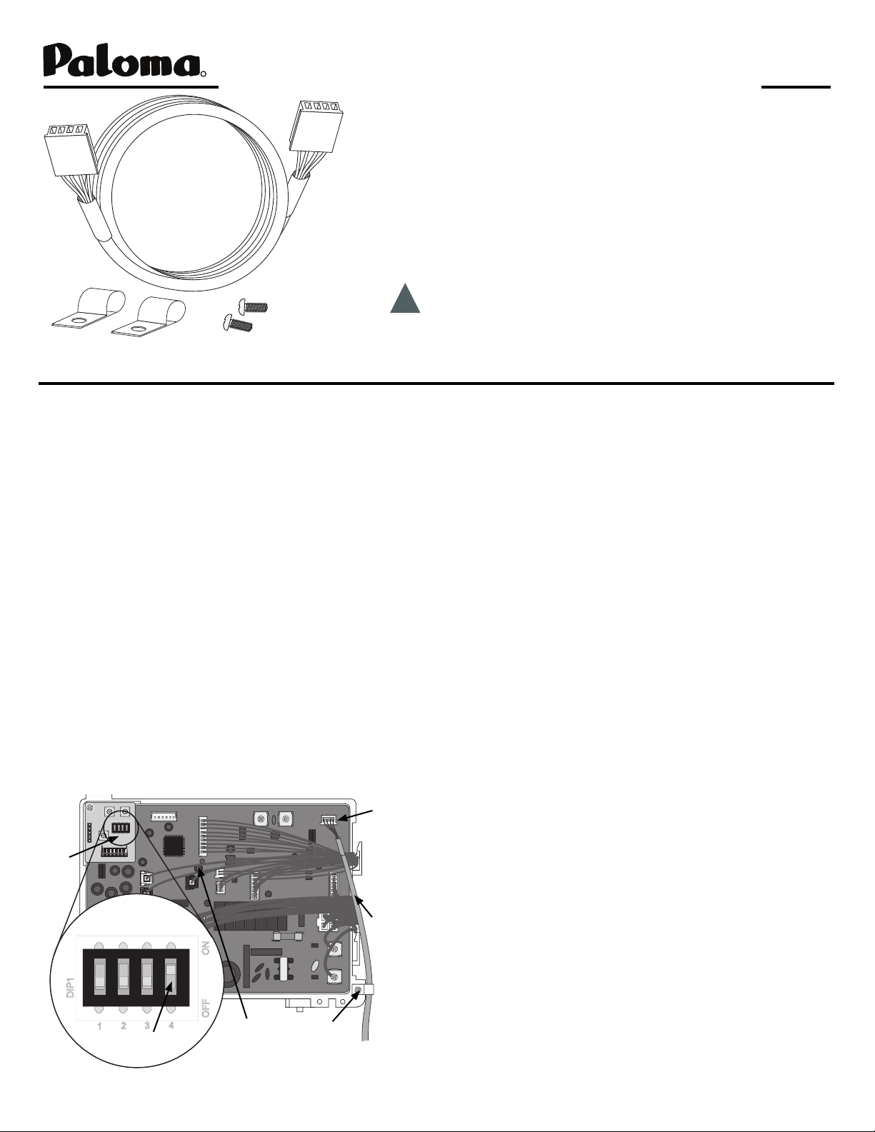
This kit contains:
1 - DUOnex™ Cable, 2 - Cable Clamps, and 2 - Screws
Install two tankless water heaters of the same model together, in a parallel plumbing application (see fi gure 2),
according to the instructions in the Instruction Manual.
NOTICE: A remote control is included with each
water heater. When using the DUOnex™ System, only
one (1) remote control is needed. Connect one remote
control to either water heater following the instructions
provided in the Instruction Manual. Keep the unused
remote control as a spare. The installed remote control
will control temperature and functionality at both
water heaters.
Make sure power is disconnected and turn off gas and
1.
water to both water heaters, then remove the front
cover from each unit.
2.
Feed one end of the DUOnex™ Cable through the
grommeted hole in the bottom of the fi rst heater.
3.
Plug the cable into the connector marked “F” in the
upper right hand corner of the PCB (see fi gure 1). The
Control Board - Figure 1
Connector
“F”
Dip
Switch
Figure 1.inset
Dip Switch
Position #4
LED
Cable clamp
and screw
DUOnex™
Cable
Refer to the Instruction Manual provided with your tankless
water heater for the proper installation procedures.
connector will only fi t one way. Press until the connector
snaps into place.
4.
Secure the DUOnex™ Cable with the clamp and screw
provided to the bottom of the control board
5.
Change the #4 dip switch setting to the “ON” position
(see fi gure 1).
(see fi gure 1 inset).
6.
Pass the other end of the DUOnex™ Cable through the
grommeted hole in the bottom of the second unit.
7.
Plug the cable into the connector marked “F” in the
upper right hand corner of the control board (see fi gure
1). The connector will only fi t one way. Press until the
connector snaps into place.
8.
Secure the DUOnex™ Cable with the clamp and screw
provided to the bottom of the control board
9.
Change the #4 dip switch setting to the “ON” position
(see fi gure 1.)
(see fi gure 1 Inset)
10.
Attach the front cover on each unit, and turn on the
power, gas, and water.
11.
Turn on the remote control and wait about one minute.
If there is no error code displayed, the setting is completed.
12.
Set the temperature at 110ºF (43ºC) and test the units by
turning on a tub or shower fi xture.
Notice: The DUOnex™ System is designed to electronically control two tankless water heaters operating as one.
Depending upon the hot water demand, one or both units
may be in operation. To test both units, increase the hot
water fl ow by turning on more than one hot water appliance
or fi xture.
PII 31-51791 (06/06)
1
Printed in U.S.A.
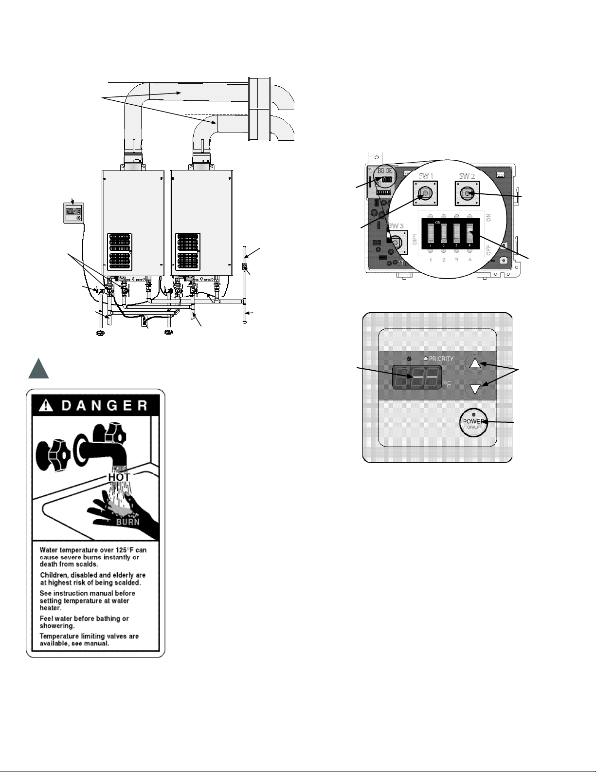
Typical Two Unit Manifold - Figure 2
Review the Instruction Manual provided with the water
heater for complete information and installation instructions.
Ven ting
Follow the
instructions in
the instruction
manual.
Units cannot
be common
vented.
Remote
Control
Wat er Isolation
Va lves
Relief Valve piped
to suitable drain.
See the instruction
manual for detailed
instructions.
Hot Water
to fi xtures
Unit 1
Grounded
Outlet
Unit 2
DUOnex™
Cable
Cold Water
Supply
Gas Supply
Follow the
instructions in
the instruction
manual for
proper pipe
sizing.
Gas supply
and cut off
Drip Leg
ting back to the “ON” position. The display on the remote
control will begin to blink a “dash”. (see fi gure 4)
While the remote is blinking a “dash” push and hold the
3.
“SW2” button (see fi gure 3) for three seconds. The display
on the remote control will stop blinking and show a solid
“dash”.
Turn on the system at the remote control and adjust to the
4.
desired temperature (see fi gure 4).(Leave the #4 dip switch
in the “ON” position.)
Dip Switches and Buttons - Figure 3
Control
Switches and
Buttons
Switch 2
Switch 1
Dip Switch
Position #4
Remote Control - Figure 4
Danger - Water Temperature Setting
Safety and energy conservation are factors to be con-
!
sidered when selecting the water temperature setting
of a water heater’s remote
control. Water temperatures
above 125°F (52°C) can
cause severe burns or death
from scalding. Be sure to
read and follow the warnings
outlined on the label pictured
to the left and information
in the Instruction Manual
provided with your tankless
water heater.
Max Tem perature
Adjustment - The factory
default temperature setting
is 120°F (49ºC). Follow
these instructions to set
the system to allow up to
140°F (60ºC) for Residential
model and 180ºF (82ºC) for
Commercial model.
Note: Only the UMC-117
Main Remote Control can
be used for 140°F (60ºC) or 180ºF (82ºC) operation.
Turn off the system at the remote control.
1.
At water heater with the remote control connected, change
2.
the #4 dip switch setting (see fi gure 3) to the “OFF” position. Wait two seconds, and change the #4 dip switch set-
LED Display
Temperature
Adjustment
Buttons
Power Button
120°F (49ºC) Max Tem perature Reset - Follow these
instructions to reset back to 120°F (49ºC) Factory Maximum
temperature setting.
Turn off the system at the remote control.
1.
At the water heater with the remote control connected,
2.
change the #4 dip switch setting (see fi gure 3) to the
“OFF” position. Wait two seconds and turn it back to the
“ON”. The remote control will display a solid “dash” (see
fi g ure 4).
Next push and hold the “SW1” button for three seconds.
3.
The display on the remote control will begin to blink a
“dash”.
4.
Turn on the system at the remote control and adjust to the
desired temperature (see fi gure 4).
To Drain Water Heater - When draining water heaters, fi rst
return the #4 dip switch setting to the “OFF” position. Follow
steps in the Instruction Manual.
2
 Loading...