

Paloform ROBATA 72 CORTEN FIRE, ROBATA 54 CORTEN FIRE, LIN-48, LIN-48P, LIN-36P Installation Manual
...
INSTALLER: Leave this manual with the appliance. CONSUMER: Retain this manual for future reference
DANGER - IF YOU SMELL GAS
1. Shut o gas to the appliance.
2. Extinguish any open ame.
3. If odor continues, keep away from the appliance and immediately call your gas
supplier or re department.
WARNING
Do not store or use gasoline or other ammable vapors and liquids in the vicinity
of this or any other appliance. An LP-cyllinder not connected for use shall not be
stored in the vicinity of this or any other appliance.
CARBON MONOXIDE HAZARD
This appliance can produce carbon monoxide which has no odor.
Using it in an enclosed space can kill you.
Never use this appliance in an enclosed space such as a camper, tent,
car or home.
WARNING:
Improper installation, adjustment, alteration, service or maintenance can cause
injury or property damage. Read the installation, operating and maintenance
instructions thoroughly before installing or servicing this equipment.
WARNING: FOR OUTDOOR USE ONLY!
DANGER
OUTDOOR FIREPIT BURNER MODELS LIN-48, LIN-48P or LIN-36, LIN-36P
ROBATA 72 & 54 CORTEN FIRE | Installation Manual
Burner conforms to: ANSI Z21.97/CSA 2.41 - (2012/10/01) “Outdoor Decorative Gas Appliances”
We recommend that our re pits be
installed and serviced by professionals
that are certied in the U.S. by NFI
(National Fireplace Institute)

2
ROBATA 72/54 CORTEN FIRE | Owner and Installation Manual
SAFETY INFORMATION
WARNINGS:
IMPORTANT: This appliance should
be inspected before use and at
least once annually by a qualied
service person.
More frequent cleaning may
be required as necessar y. It
is imperative that the control
compartment, burners and
circulating air passageways of the
appliance be kept clean.
DANGER: Carbon monoxide
poisoning can lead to death!
CARBON MONOXIDE POISONING:
Early signs of carbon monoxide
poisoning resemble the u, with
symptoms including headache, dizziness,
or nausea. If you experience these signs,
the Fire Pit may not be working properly.
Get fresh air at once! Have the Fire Pit
serviced. Some people are more aected
by carbon monoxide than others,
including pregnant women, people with
heart or lung disease or anemia, those
under the inuence of alcohol, and those
at high altitudes.
NATURAL GAS AND PROPANE:
To assist in detecting leaks, an odorant
has been added to natural gas and
propane. However, this odorant can fade,
and gas may be present even though no
odor exists. Make certain you read and
understand all warnings. Keep this manual
for reference. It is your guide to safe and
proper operation of this appliance.
WARNING: Any modication to this appliance or its
controls can be dangerous.
1. This appliance, as supplied, is only for use with the
type of gas indicated on the rating plate.
2. When this appliance is connected to a xed piping
system, the installation must conform to local codes,
or in the absence of local codes, to the National
Fuel Gas Code, ANSI Z223.1/NFPA 54, or the
International Fuel Gas Code.
3. Keep the appliance area clear and free from
combustible materials, gasoline and other ammable
vapors and liquids
4. Do not burn solid fuel in this appliance. Do not use
this appliance to cook food or to burn paper or other
objects.
5. Children and adults should be alerted to the
hazards of high surface temperatures and should
stay away to avoid burns or clothing ignition.
6. Clothing or other ammable materials should not
be hung from the appliance, or placed on or near
the appliance.
7. Young children should be carefully supervised
when they are in the area of the appliance.
8. This appliance, when installed, must be electrically
grounded in accordance with local codes or, in the
absence of local codes, with the National Electrical
Code, ANSI/NFPA 70.
9. Do not use the appliance if any part has been under
water. Immediately call a qualied service technician
to inspect the appliance and to replace any part of
the control system and any gas control which has
been under water.
10. Inspect the appliance before each use.
11. Turn the appliance o and let cool before servicing,
installing, repairing or covering. Any guard or other
protective device removed for servicing the
appliance must be replaced prior to operating the
appliance. Only a qualied service person should
install, service, or repair the appliance.
HIGH ALTITUDE INSTALLATION
The appliance is rated for installations up to 4500’ (1372
m) above sea level. Above 4500’ the appliance must be
derated at the factory for the appropriate altitude unless
the local fuel is pre derated.
LOCAL CODES
Install and use your Outdoor Fire Pit with care. Follow
local codes. In the absence of local codes, use the latest
edition of The National Fuel Gas Code ANSI Z223.1/
NFPA 54 available from:
American National Standards Institute Inc.
1430 Broadway
New York NY 10018
National Fire Protection Association, Inc.
Batterymarch Park
Quincy MA 02269.
All wiring shall be in compliance with all local, city, and
state codes. The appliance, when installed, must be
electrically grounded in accordance with local codes, or
in the absence of local codes, with the National Electrical
Code ANSI/ NFPA 70 (latest edition) and Canadian
Electrical Code, CSA C22.1.
3
ROBATA 72/54 CORTEN FIRE | Owner and Installation Manual
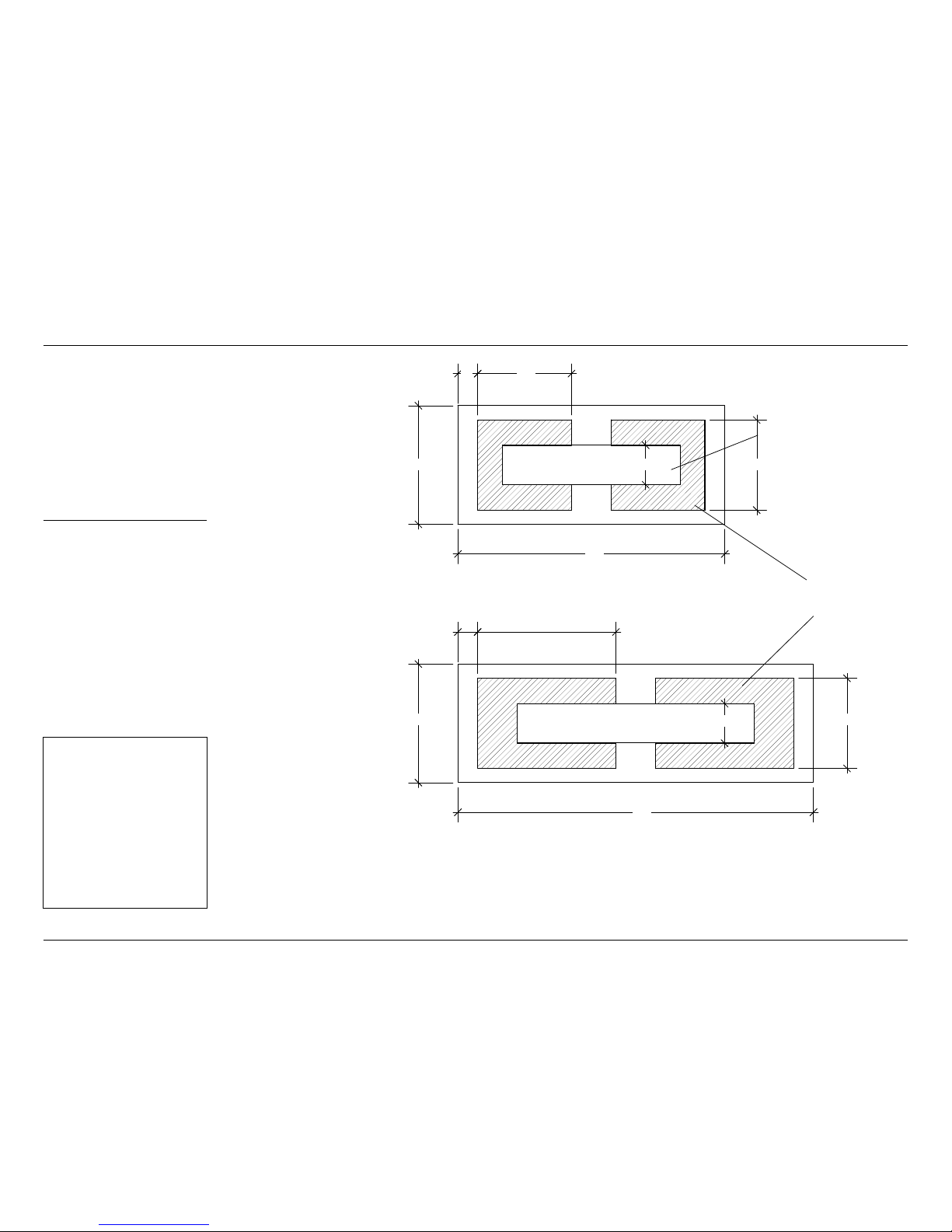
POSITIONING GAS & ELECTRICAL SUPPLY
Robata has an open base
through which you can
bring a gas or propane
line and electrical service.
See Fig. 1 (hatched areas)
Please make sure that the
gas line and power supply
are located only within these
areas. This will ensure that the
nal position of the unit will
not be compromised.
FIG 1. BASE DIAGRAMS
See page 12 of this
manual for Gas Installation
Requirements
This appliance requires
110V AC power supply in
the form of an outdoor
receptacle installed inside
the unit body.
ATTENTION:
Gas and electrical lines
must be installed by
licensed contractors in
compliance with local
codes. Main power must
be o when connecting
to main electrical power
supply or performing
service.
OPENINGS FOR GAS
AND ELECRICAL
LOCATION OF BURNER
ROBATA 54
CORTEN
19”
54”
8”24”
4”
18 1/4”
LIN-36 BURNER
ROBATA 72
CORTEN
72”
8”
24” 18 1/4”
LIN-48 BURNER

4
ROBATA 72/54 CORTEN FIRE | Owner and Installation Manual
1. Please refer to ‘Clearances to Combustibles’ guide on page 6 of this guide for placement.
2. Ensure that the nal location for the re pit is as at and level as possible. Provide adequate drainage
beneath the opening in the base of the re pit vessel.
3. Completely unpack the re pit. If crated, remove the sides of the crate to make lifting the re pit easier.
4. Some components may be packed inside the Robata housing.
5. Remove the Corten Cover (4) and set aside
6. Remove Burner Assembly (3) from re pit vessel and carefully set aside.
7. Carefully lift the re pit and place it in its nal position. If there is a gas riser and power receptacle, re pit
vessel should be placed so that the stubs are enclosed within the Robata Body (1), but do not interfere with
the centre 8” of the unit (see page 3)
8. If the Robata Body (1) does not sit at, shim appropriately so that it is well and evenly supported.
9. Connect Gas and Electrical as per page 7.
10. Check for leaks, test burner and complete installation as per pages 7-8.
CAUTION:
HEAVY: Use care
when lifting and
placing to avoid
injury and damage
to property and the
re pit itself. Fire pits
will require 2 or more
people to lift.
ATTENTION: Cor-Ten Steel is designed to rust in order to form a protective layer that resists further
corrosion. This layer can take months to stabilize depending on climate and weather conditions.
Rust will bleed until it stabilizes. Do not place Cor-Ten re pits on surfaces that will be permanently
damaged or stained by rust bleed.
PLACEMENT AND ASSEMBLY
5
ROBATA 72/54 CORTEN FIRE | Owner and Installation Manual
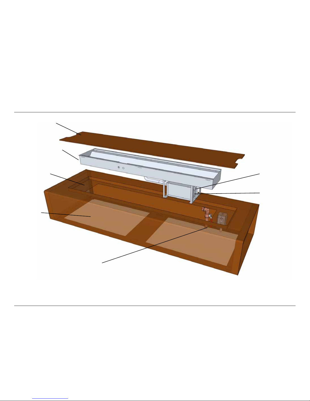
COMPONENTS
FIG 2. ROBATA CORTEN EXPLODED VIEW (72” MODEL SHOWN)
2. Media Tray
Suggested location for gas and electrical.
RECOMMENDED: Outdoor receptacle with
weatherproof “in-use” cover.
3. Burner Assembly
(LIN-36 & 48)
4. Corten Cover
5. Gas Connection
6. Power Connection
24 VAC
1. Body
6
ROBATA 72/54 CORTEN FIRE | Owner and Installation Manual
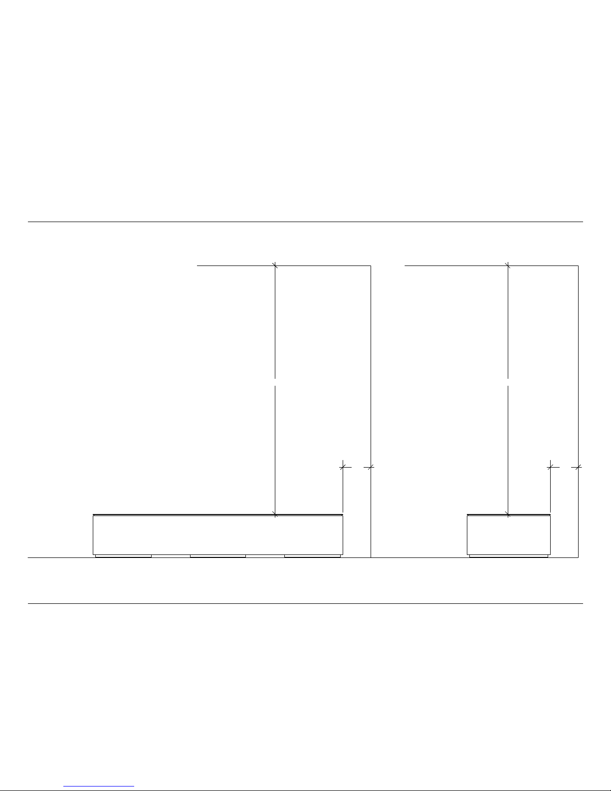
FIG 3. MINIMUM CLEARANCES TO COMBUSTIBLES
CLEARANCE TO COMBUSTIBLES
72”
8” 8”
72”

7
ROBATA 72/54 CORTEN FIRE | Owner and Installation Manual
APPROVED FLEXIBLE GAS HOSE
A.G.A DESIGN-CERTIFIED MANUAL
SHUTOFF VALVE WITH 1/8” NPT TAP
3” MINIMUM
CAP PIPE NIPPLE TEE JOINT
FROM GAS METER (5” W.C.
TO 10.5” W.C. PRESSURE)
SEDIMENT TRAP
CONNECTING TO GAS SUPPLY
WARNING:
A qualied ser vice person must
connect the appliance to the gas
supply. Follow all local codes.
CAUTION:
Use only new black iron or steel pipe.
Internally tinned copper tubing may be
used in certain areas. Use pipe of 1/2”
diameter or greater to allow proper
gas volume to Outdoor Fire Pit Burner.
If pipe is too small, undue loss of
pressure will occur.
INSTALLATION ITEMS NEEDED:
Before installing the Outdoor
Fire Pit, make sure you have all items
listed bellow:
• piping (check local codes)
• sealant
• manual shuto valve
• adjustable (crescent) wrench or pliers
• sediment trap
• tee joints
• pipe wrench
INSTALLATION REQUIREMENTS
Installation must include a manual shuto valve, union,
and plugged 1/8” NPT tap. Locate NPT tap within reach
for test gauge hook up. NPT tap must be upstream from
the appliance.
Apply pipe joint sealant lightly to male threads. This will
prevent excess sealant from going into pipe. Excess
sealant in pipe could result in a clogged burner injector.
Install sediment trap in supply line as shown below.
Locate sediment trap where it is within reach for cleaning
and trapped matter is not likely to freeze.
A sediment trap prevents moisture and contaminants
from entering the Outdoor Fire Pit controls. If a sediment
trap is not installed, or is installed incorrectly, the unit may
not work properly.
CHECKING GAS CONNECTION
WARNING: Test all gas piping and connections
for leaks after installing or servicing. Correct all leaks
immediately.
WARNING: Never use an open ame to check
for a leak. Apply a mixture of liquid soap and water
to all joints. Bubbles forming on joints while the
gas is running indicate a leak. Correct all leaks at
immediately.
Test Pressures in Excess Of 1/2 psi (3.5 kPa)
This appliance and its individual shuto valve must be
disconnected from the gas supply piping system during
any pressure testing of that system at test pressures in
excess of ½ psi (3.5 kPa).
Test Pressures Equal To or Less Than 1/2 psi (3.5 kPa)
This appliance must be isolated from the gas supply
piping system by closing its individual manual shuto
valve during any pressure testing of the gas supply piping
system at test pressures equal to or less than ½ psi (3.5
kPa).

8
ROBATA 72/54 CORTEN FIRE | Owner and Installation Manual
TO ASSEMBLE THE BURNER
1. Remove the Burner Assembly and Burner Media from packaging (see Parts List on page 16).
2. Connect the Burner Assembly to the gas supply using the supplied ex connector and following the
instructions on page 7.
3. Carefully leak test all connections following the procedure on page 7.
4. Fill the burner trough evenly with burner media (NG - crushed tempered glass; LP - volcanic rock). Do not
obstruct the pilot ignition port with burner media! Do not use media not supplied by Paloform!
5. Place the burner assembly on a stable surface. Ensure burner is level.
6. Follow the Initial Lighting Instructions on page 10. Make sure that the ame is even along the burner
length and appliance is fully operational and safe for use. Turn OFF the appliance and let it cool before
proceeding to the next step.
7. Carefully lift the burner and place it in the Robata body. (See page 5)
8. Place and evenly distribute decorative topping media (lava rock or tempered glass pebble) on top of burner
media. Completely ll topping receptacle. Decorative media can be brought level with the top of the pilot cover.
Do not obstruct PILOT IGNITION PORT!
WARNING:
Failure to position parts in
accordance with these diagrams
and instructions and/or failure to
use par ts specically approved for
use with this appliance may result in
property damage or personal injury.
Do not remove t he metal data
plates attached to the Outdoor Fire
Pit Burner. These plates contain
important information.
NOTICE:
Installation and repair should be
done by a qualied service person.
The appliance should be inspected
before use and at least once annually
by a qualied service person. More
frequent cleaning may be required
as necessary. It is imperative that
control compartment, burner and
circulating air passageways of the
appliance be kept clean.
CAUTION:
New Lava Rock may pop or crackle
when rst heated. This should
subside after 30 minutes to one hour
or more of operation. Maintain safe
distance during this time.
BURNER ASSEMBLY
PILOT IGNITION PORT

9
ROBATA 72/54 CORTEN FIRE | Owner and Installation Manual
NOTES ABOUT COVERS
WARNING:
To avoid accidental ignition,
always turn o gas and lock out
power supply when covering re
pit.
Robata includes two covers: a fabric,
all-weather cover and a stainless
steel insert which converts your re
pit into a table when not in use.
To ensure that stainless steel insert
seats properly, decorative toppings
must be arranged below the level of
the stainless steel top (See Fig. 4).
FIG 4. SECTION DIAGRAM - STAINLESS STEEL COVER
Top
Burner Media
(Crushed Glass for NG
Lava Rock for LP)
Decorative Media:
Must be kept below this line
10
ROBATA 72/54 CORTEN FIRE | Owner and Installation Manual
LIGHTING YOUR FIRE PIT
WARNINGS:
Failure to follow these instructions exactly may result
in re or explosion causing property damage, personal
injury or loss of life.
Before operating the appliance, check all around the
appliance area and on the surrounding oor for the smell
of gas - some gas is heavier than air and may settle on the
oor in the event of a leak. IF YOU SMELL GAS, follow the
safety instructions on page 1 of this manual.
This appliance is equipped with an ignition device that
automatically lights the pilot. Do not try to light the pilot
manually.
The main gas valve in this appliance is not serviceable
and does not have any control knobs or switches to
operate. Do not remove the heat shields covering the
valve and electronic devices. Do not try to repair or modify
the valve, as doing so may result in a re or explosion.
Call a qualied service technician if you have any safety
concerns.
Do not use this appliance if any part of it has been under
water. Immediately call a qualied service technician to
inspect the appliance and to replace any part of the control
system and any gas control that has been under water.
Improper installation, adjustment, alteration, service or
maintenance can result in injury or property damage. For
assistance or additional information, consult a qualied
installer, service agency or the gas supplier.
Do not store or use gasoline or other ammable vapors or
liquids in the vicinity of this appliance.
INITIAL LIGHTING INSTRUCTIONS
Before placing burner assembly into a housing:
1. Purge air from the supply line.
2. Test for leaks in each of the following locations:
• The gas supply line connection to the main valve;
• The Burner connections and pilot;
• All joints on the valve and control body;
• All eld made joints and gas shuto valves;
• All factory made joints and connections.
3. You may check for gas leaks using one of the following methods only:
• Soap and water solution. WARNING: If using a soap and water solution to
test for leaks, DO NOT spray the solution onto electronic parts;
• An approved leak testing spray;
• An electronic snier. NOTE: Remove any excess pipe compound from
connections if using this method, as the compound can set o electronic sniers.
DANGER: NEVER USE AN OPEN FLAME TO CHECK FOR GAS LEAKS.

11
ROBATA 72/54 CORTEN FIRE | Owner and Installation Manual
OPERATING INSTRUCTIONS
1. STOP! Read the safety information on pages 1, 2 and 7 of this
manual.
2. Turn o all electric power to the appliance.
3. Do not attempt to light the pilot manually.
4. Turn the manual gas control valve to the OFF position.
5. Wait ve (5) minutes to clear out any residual gas, then check for the smell
of gas at and around the appliance, including near the oor. If you smell
gas, STOP! Follow the instructions on page 1 of this manual. If you do
not smell gas, continue to the next step.
6. Turn the manual gas control valve to the ON position.
7. Plug the supplied 24 VAC AC adapter into a 110V power outlet.
8. Connect the AC adapter to the AC input plug at the unit.
9. Place Burner Assembly in Housing
10. To ignite burner, turn on electric power to the appliance.
11. To turn o appliance, turn o electric power to the appliance.
TURNING OFF THE GAS TO THE APPLIANCE
1. Turn o all electric power supplied to the appliance if service is to be
performed. Unplug the 24 VAC AC adapter from the power outlet.
2. If necessary, remove the burner from the housing to access the manual
gas valve.
3. Turn the main manual shuto valve to the full OFF position.
LIGHTING YOUR FIRE PIT
WARNING:
This appliance is designed to be connected to a power
source that is controllable by a switch.
Do not connect 24 VAC AC adapter to a live powe r
source.

12
ROBATA 72/54 CORTEN FIRE | Owner and Installation Manual
TECHNICAL DATA
Burner Dimensions
Burner Specications
Minimum Clearances to Combustible Materials:
MODEL # MAX INPUT
Btu/Hr
INLET
PRESSURE MIN
INLET
PRESSURE MAX
MANIFOLD
PRESSURE
ORIFICE SIZE BURNER PORTS PORT SIZE
LIN-36 60,000 4.5” W.C. 10.5” W.C. 3.5” W.C. 26 35 1/8”
LIN-48 80,000 4.5” W.C. 10.5” W.C. 3.5” W.C. 18 47 1/8”
LIN-36P 57,000 11.0” W.C. 13.0” W.C. 10.0” W.C. 43 35 1/8”
LIN-48P 77,000 11.0” W.C. 13.0” W.C. 10.0” W.C. 37 47 1/8”
ELECTRICAL (ALL MODELS)
120V 15A OUTDOOR RECEPTACLE - DEDICATED CIRCUIT WITH WALL SWITCH. BURNER CONNECTS VIA AN AC ADAPTER.
MUST BE INSTALLED AND GROUNDED IN ACCORDANCE WITH LOCAL CODES
ABOVE LONG SIDE SHORT SIDE BELOW
72” 8” 16” 0”
48” (LIN-48), 36” (LIN-36)
10”
9”
8”

13
ROBATA 72/54 CORTEN FIRE | Owner and Installation Manual
CLEANING AND MAINTENANCE
WARNING: Turn o gas before servicing re pit. It is recommended that
a qualied service technician perform these check-ups at the beginning
of each re pit season.
If any irregularities are apparent with operation, please refer to Troubleshooting
guide, pages 13-14.
BURNER ELEMENT AND PILOT
Keep the burner and pilot area clean by vacuuming or brushing at least twice a year.
Make sure the burner porting and burner air openings are free of obstructions at all
times.
Inspect area around the burner. Remove any lint or foreign material with a brush or
vacuum cleaner.
If it evident that the burner is damaged, the burner must be replaced prior to the
appliance being put into operation
PILOT FLAME
The ames from the pilot should be
visually checked as soon as the unit
is installed, and periodically during
normal operation. The pilot ame
must always be present when the
replace is in operation or connected
to the gas line with the main shuto
valve open and the IPS activated
(powered). The pilot ame has two
distinct ames: one engulng the
ame sensor, and the other reaching
to the main burner.
Burner Element
Pilot Assembly
14
ROBATA 72/54 CORTEN FIRE | Owner and Installation Manual
TROUBLESHOOTING
WARNING:
Turn o appliance and let cool before
servicing. Only a qualied service
person should service and repair this
appliance.
IF YOU SMELL GAS:
Shut o gas supply.
Do not try to light any appliance.
Do not touch any electrical switch; do not use any phone in t he vicinity of the appliance.
Immediately call your gas supplier from a safe dis tance. Follow your gas supplier’s instructions.
IMPORTANT: Operating unit where
impurities in air exist may create
odors. Cleaning supplies, paint,
paint remover, cigarette smoke,
cements and glues, new carpet or
textiles, etc., create fumes. These
fumes may mix with combustion
air and create odors. These odors
will disappear over time.
OBSERVED PROBLEM POSSIBLE CAUSE REMEDY
Burner shuts o/relights intermittently. 1. Wind or gusts in excess of 16 km/h
(10 mph).
2. Air present in gas line
1. Protect pilot from wind with
decorative topping - sides of pilot
housing may be covered. DO
NOT BLOCK IGNITION PORT.
In the case of consistently windy
conditions, a protective glass
barrier may be necessary.
2. Ensure gas line is thoroughly bled
Unit is smoking / sooting excessively.
(Note: It is natural and unavoidable for
appliance sets to produce moderate
levels of carbon (soot) where ames
contact the media.)
1. Poor fuel quality
2. Excessive ame impingement or
blockage
3. Improper fuel/air mixture
1. Contact local natural gas
company
2. Separate the stones to allow
more ame passage
3. Remove any foreign items from
the ame pattern and/or check
for proper orice sizing
Burner is excessively noisy
(Note: The movement and combustion
of gas will create low, unavoidable
levels of noise.)
1. Passage of air/gas across irregular
surfaces
2. Excessive gas pressure on natural
gas units
1. Relieve any tight bends or kinks
in gas supply line
2. Check/reset gas regulator
pressure
Gas odor even when power is o 1. Gas leak. See Warning statement
above.
2. Main gas valve defective.
1. Locate and correct all leaks (see
Checking Gas Connections, pg 5)
2. Replace gas valve
Unit produces unwanted odors 1. Gas leak. See Warning statement
below.
1. Locate and correct all leaks (see
Checking Gas Connections, pg 5)

15
ROBATA 72/54 CORTEN FIRE | Owner and Installation Manual
WARNING:
Turn o appliance and let cool before
servicing. Only a qualied service
person should service and repair this
appliance.
TROUBLESHOOTING cont’d
OBSERVED PROBLEM POSSIBLE CAUSE REMEDY
When power is turned on, nothing
happens
1. No power to unit 1. Check connections between
controls, power adapter and
power source
2. Check power at source
3. Verify that power adapter is
functioning correctly
4. If you are using a third-party
remote control unit, verify that
this unit is functioning correctly
When power is turned on, there is a
spark at pilot but no ignition
1. Gas supply turned o or manual
shuto valve closed
2. Air in gas lines when installed
3. Pilot is clogged
4. Pilot valve lead is loose/
disconnected
1. Turn o gas supply or open
manual shuto valve
2. Purge air from the supply line
3. Clean pilot (see Cleaning and
Maintenance, page 9) or replace
pilot assembly
4. Check/reconnect lead
Burner does not light after pilot is lit 1. Burner orice is clogged
2. Inlet gas pressure is too low
3. Burner orice diameter is too small
4. Flame sensor lead loose/
disconnected
5. Main valve lead is loose/
disconnected
1. Clean burner orice
2. Contact local gas or propane
supplier
3. Replace burner orice
4. Reconnect lead
5. Reconnect lead
Delayed burner ignition 1. Lighting port is blocked 1. Remove burner media/debris
from Lighting Port
Burner ame is too low or too high 1. Incorrect gas supply or pressure
2. Blocked burner orice or burner
ports
3. Improper burner orice size
1. Check for proper gas supply
pressure
2. Free burner orice and burner
ports of any burrs, paint, or other
blockage
3. Verify proper burner orice sizing
(see page 5)

16
ROBATA 72/54 CORTEN FIRE | Owner and Installation Manual
ILLUSTRATED PARTS LIST
WARNING: Failure to position parts in accordance with diagrams or failure to use parts specically approved for this appliance may result in property
damage or personal injury.
REPLACEMENT PARTS ARE AVAILABLE THROUGH THE MANUFACTURER
4
1
3
12
KEY # DESCRIPTION QTY LIN-72 LIN-72P
1
2
3
4
5
6
7
8
9
10
11
12
13
14
15
Straight Burner w/ Venturi
Throat Plate Set (two pieces)
Burner Tray & Chassis
Control Box c/w Cover
Pilot Assembly
Pilot Shroud
Pilot Cover
3/8”MPT x 3/8” MPT Orice
Main Gas Valve
Ignition Control Board
Wire Harness
Main Flex Connector
Adapter 24 VAC, 750 mA (not shown)
Burner Media
Topping Media
1
1
1
1
1
1
1
1
1
1
1
1
1
PKG
PKG
PKG
LB14V072
LB14001
LB14072
CBLIN
NA410
EPCLIN01
EPCLIN02
OAM004
GVBGD258
CC-9120-30
AUCE-WH-01
FC0002
AC24-750
crushed glass
various
LB14V072
LB14001
LB14072
CBLIN
NA410P
EPCLIN01
EPCLIN02
OAM030
GVBGD258P
CC-9120-30
AUCE-WH-01
FC0002
AC24-750
crushed lava
various

17
ROBATA 72/54 CORTEN FIRE | Owner and Installation Manual
ILLUSTRATED PARTS LIST cont’d
1
7
2
5
6
9
1011
3
8

18
ROBATA 72/54 CORTEN FIRE | Owner and Installation Manual
ILLUSTRATED PARTS LIST
Wiring Diagram
1 2 3 4 5 106 7 118 9
MAIN
GND (VALVE)
PILOT
GND (BURNER)
GND
24V
SENSE
SPARK
AC POWER ADAPTER
INPUT: AC 120V 60 Hz 8A
OUTPUT: 24 VAC , 750 mA
CHASSIS GROUND
PILOT: NA410 OR LP410
IGNITION CONTROL BOARD: CC-9120-30
GAS VALVE: GVBGD258

19
ROBATA 72/54 CORTEN FIRE | Owner and Installation Manual
WARRANTY INFORMATION
KEEP THIS FOR WARRANTY
MODEL: (circle one) Robata 72/54
LIN-48
LIN-48P
LIN-36
LIN-36P
SERIAL NO:
DATE PURCHASED:
OUTDOOR FIRE PIT BURNER: LIMITED LIFETIME WARRANTY
The following components are warranted for life to the original owner, subject to proof of purchase:
Outdoor Fire Pit Burner - manufactured by Paloform Inc.
BASIC WARRANTY
Paloform Inc. warrants the components and materials in your appliance to be free from manufacturing and material
defects for a period of one year from date of installation. After installation, if any of the components manufactured
by Paloform Inc. in the appliance are found to be defective in materials or workmanship, Paloform Inc. will, at its
option, replace or repair the defective components at no charge to the original owner. Paloform Inc. will also pay
for reasonable labor cost incurred in replacing or repairing such components for a period of one year from date of
installation. Any products presented for warranty repair must be accompanied by a dated proof of purchase.
This Limited Lifetime Warranty will be void if the appliance is not installed by a qualied installer in accordance
with installation instructions. The Limited Lifetime Warranty will also be void if the appliance is not operated and
maintained according to the operating instructions supplied with the appliance, and does not extend to (1) re pit
burner assembly damaged by accident, neglect, misuse, abuse, alterations, negligence of others, including the
installation thereof by unqualied installers, (2) the costs of removal, reinstallation or transportation of defective
parts on the appliance, or (3) incidental or consequential damage. All service work must be performed by an
authorized service representative.
This warranty is expressly in lieu of other warranties, express or implied, including the warranty of merchantability
of tness for purpose and of all other obligations or liabilities. Paloform Inc. does not assume for it any other
obligations or liabilities in connection with sale or use of the appliance. In states that do not allow limitations on
how long an implied warranty lasts, or do not allow exclusion of indirect damage, those limitations of exclusions
may not apply to you. You may also have additional right not covered in the Limited Lifetime Warranty. Paloform
Inc. reserves the right to investigate any and all the claims against this Warranty and decide upon method of
settlement. For information about this warranty contact:
Paloform Inc
2680 Matheson Blvd E
Suite 102
Mississauga ON L4W 0A5
Canada
Paloform Inc - 1.888.823.8883 info@paloform.com paloform.com
 Loading...