


PA-5200 Series Next-Gen Firewall
Hardware Reference
paloaltonetworks.com/documentation

Contact Information
Corporate Headquarters:
Palo Alto Networks
3000 Tannery Way
Santa Clara, CA 95054
www.paloaltonetworks.com/company/contact-support
About the Documentation
• For the most recent version of this guide or for access to related documentation, visit the Technical
Documentation portal www.paloaltonetworks.com/documentation.
• To search for a specific topic, go to our search page www.paloaltonetworks.com/documentation/
document-search.html.
• Have feedback or questions for us? Leave a comment on any page in the portal, or write to us at
documentation@paloaltonetworks.com.
Copyright
Palo Alto Networks, Inc.
www.paloaltonetworks.com
©
2019-2019 Palo Alto Networks, Inc. Palo Alto Networks is a registered trademark of Palo
Alto Networks. A list of our trademarks can be found at www.paloaltonetworks.com/company/
trademarks.html. All other marks mentioned herein may be trademarks of their respective companies.
Last Revised
April 8, 2019
2 PA-5200 SERIES NEXT-GEN FIREWALL HARDWARE REFERENCE |

Table of Contents
Before You Begin................................................................................................5
Tamper Proof Statement........................................................................................................................... 7
Third-Party Component Support.............................................................................................................8
Product Safety Warnings.......................................................................................................................... 9
PA-5200 Series Firewall Overview.............................................................. 13
PA-5200 Front Panel............................................................................................................................... 15
PA-5200 Back Panel................................................................................................................................ 18
Install the PA-5200 Series Firewall in an Equipment Rack..................... 19
Install the PA-5200 Series Firewall in a 19-inch Equipment Rack................................................21
Install the Four-Post Rack Kit on a PA-5200 Series Firewall.........................................................22
Connect Power to a PA-5200 Series Firewall........................................... 25
Connect AC Power to a PA-5200 Series Firewall............................................................................ 27
Connect DC Power to a PA-5200 Series Firewall............................................................................28
Service the PA-5200 Series Firewall........................................................... 31
Interpret the LEDs on a PA-5200 Series Firewall............................................................................ 33
Replace the Air Intake Filters on a PA-5200 Series Firewall......................................................... 35
Replace a Fan Tray on a PA-5200 Series Firewall........................................................................... 37
Replace a Power Supply on a PA-5200 Series Firewall.................................................................. 38
Replace an AC Power Supply on a PA-5200 Series Firewall.............................................38
Replace a DC Power Supply on a PA-5200 Series Firewall...............................................39
Replace a Drive on a PA-5200 Series Firewall..................................................................................41
Replace a Log Drive on a PA-5200 Series Firewall............................................................. 41
Replace a System Drive on a PA-5200 Series Firewall.......................................................45
PA-5200 Series Firewall Specifications.......................................................51
PA-5200 Series Physical Specifications.............................................................................................. 53
PA-5200 Series Electrical Specifications.............................................................................................54
PA-5200 Series Environmental Specifications...................................................................................55
PA-5200 Series Miscellaneous Specifications................................................................................... 56
PA-5200 Series Firewall Compliance Statements Overview..................57
PA-5200 Series Firewall Compliance Statements............................................................................ 59
TABLE OF CONTENTS iii

iv TABLE OF CONTENTS

Before You Begin
Read the following topics before you install or service a Palo Alto Networks® next-generation
firewall or appliance. The following topics apply to all Palo Alto Networks firewalls and
appliances except where noted.
> Tamper Proof Statement
> Third-Party Component Support
> Product Safety Warnings
5

6 PA-5200 SERIES NEXT-GEN FIREWALL HARDWARE REFERENCE | Before You Begin
©
2019 Palo Alto Networks, Inc.

Tamper Proof Statement
To ensure that products purchased from Palo Alto Networks were not tampered with during shipping, verify
the following upon receipt of each product:
• The tracking number provided to you electronically when ordering the product matches the tracking
number that is physically labeled on the box or crate.
• The integrity of the tamper-proof tape used to seal the box or crate is not compromised.
• The integrity of the warranty label on the firewall or appliance is not compromised.
(PA-7000 Series firewalls only) PA-7000 Series firewalls are modular systems and therefore
do not include a warranty label on the firewall.
PA-5200 SERIES NEXT-GEN FIREWALL HARDWARE REFERENCE | Before You Begin 7
©
2019 Palo Alto Networks, Inc.

Third-Party Component Support
Before you consider installing third-party hardware, read the Palo Alto Networks Third-Party Component
Support statement.
8 PA-5200 SERIES NEXT-GEN FIREWALL HARDWARE REFERENCE | Before You Begin
©
2019 Palo Alto Networks, Inc.

Product Safety Warnings
To avoid personal injury or death for yourself and others and to avoid damage to your Palo Alto Networks
hardware, be sure you understand and prepare for the following warnings before you install or service the
hardware. You will also see warning messages throughout the hardware reference where potential hazards
exist.
All Palo Alto Networks products with laser-based optical interfaces comply with 21 CFR
1040.10 and 1040.11.
The following safety warnings apply to all Palo Alto Networks firewalls and appliances, unless a specific
hardware model is specified.
• When installing or servicing a Palo Alto Networks firewall or appliance hardware component that has
exposed circuits, ensure that you wear an electrostatic discharge (ESD) strap. Before handling the
component, make sure the metal contact on the wrist strap is touching your skin and that the other end
of the strap is connected to earth ground.
French Translation: Lorsque vous installez ou que vous intervenez sur un composant matériel de
pare-feu ou de dispositif Palo Alto Networks qui présente des circuits exposés, veillez à porter un
bracelet antistatique. Avant de manipuler le composant, vérifiez que le contact métallique du bracelet
antistatique est en contact avec votre peau et que l’autre extrémité du bracelet est raccordée à la terre.
• Use grounded and shielded Ethernet cables to ensure agency compliance with electromagnetic
compliance (EMC) regulations.
French Translation: D es câbles Ethernet blindés reliés à la terre doivent être utilisés pour garantir la
conformité de l'organisme aux émissions électromagnétiques (CEM).
• (PA-220 firewalls only) The PA-220 firewall meets the requirements of IEC 61000-4-5 surge immunity
test. To prevent damage from electrical surges on Ethernet ports, we recommend that you use an
Ethernet surge protection device with the following specifications:
• Rated for Gigabit Ethernet up to category 5E and minimum 1Gbps.
• Protection provided on all eight signal leads.
• Both line-to-line and line-to-ground/shield are provided.
• Protection device must be connected to earth ground and use shielded category 5E or higher
Ethernet cable.
Technical Specifications:
• Protective circuit complies with IEC test classifications B2, C1, C2, C3, and D1.
• Normal discharge current (core to earth ground) is 2kA per signal pair.
• Normal discharge current (core to core) is 100A.
• Total discharge current is 10kA.
• French Translation: (PA-220 uniquement) Les pare-feux PA-220 sont conformes aux exigences du test
d’immunité aux surtensions IEC 61000-4-5. Pour éviter les dommages résultant de surtension électrique
sur les ports Ethernet, il est recommandé d’utiliser un dispositif de protection contre les surtensions aux
caractéristiques suivantes:
• Gigabit Ethernet jusqu’à la catégorie 5E, débit 1 Go/s minimum.
• Protection sur les huit câbles signal.
• Le blindage et la mise à la terre “ligne à ligne” et “ligne à la terre” sont fournis.
• Le dispositif de protection doit être raccordé à la terre et un câble Ethernet blindé de catégorie 5E ou
supérieure doit être utilisé.
Caractéristiques techniques:
PA-5200 SERIES NEXT-GEN FIREWALL HARDWARE REFERENCE | Before You Begin 9
©
2019 Palo Alto Networks, Inc.

• Le circuit de protection est conforme aux classifications de test IEC B2, C1, C2, C3, et D1.
• Le courant de décharge normal (cœur vers terre) est de 2kA par paire de signal.
• Le courant de décharge normal (cœur vers cœur) est de 100 A.
• Le courant de décharge total est de 10kA.
• Do not connect a supply voltage that exceeds the input range of the firewall or appliance. For details
on the electrical range, refer to electrical specifications in the hardware reference for your firewall or
appliance.
French Translation: Veillez à ce que la tension d’alimentation ne dépasse pas la plage d’entrée du
pare-feu ou du dispositif. Pour plus d’informations sur la mesure électrique, consulter la rubrique des
caractéristiques électriques dans la documentation de votre matériel de pare-feu ou votre dispositif.
• Do not replace a battery with an incorrect battery type; doing so can cause the replacement battery to
explode. Dispose of used batteries according to local regulations.
French Translation: Ne remplacez pas la batterie par une batterie de type non adapté, cette dernière
risquerait d’exploser. Mettez au rebut les batteries usagées conformément aux instructions.
• (All firewalls with two or more power supplies) Disconnect all power cords (AC or DC) from the power
inputs to fully de-energize the hardware.
French Translation: (Tous les pare-feux avec au moins deux sources d’alimentation) Débranchez tous les
cordons d’alimentation (c.a. ou c.c.) des entrées d’alimentation et mettez le matériel hors tension.
• (PA-7000 Series firewalls only) When removing a fan tray from a PA-7000 Series firewall, first pull the
fan tray out about 1 inch (2.5cm) and then wait a minimum of 10 seconds before extracting the entire
fan tray. This allows the fans to stop spinning and helps you avoid serious injury when removing the
fan tray. You can replace a fan tray while the firewall is powered on but you must replace it within 45
seconds and you can only replace one fan tray at a time to prevent the thermal protection circuit from
shutting down the firewall.
French Translation: (Pare-feu PA-7000 uniquement) Lors du retrait d’un tiroir de ventilation d’un pare-
feu PA-7000, retirez tout d’abord le tiroir sur 2,5 cm, puis patientez au moins 10 secondes avant de
retirer complètement le tiroir de ventilation. Cela permet aux ventilateurs d’arrêter de tourner et permet
d’éviter des blessures graves lors du retrait du tiroir. Vous pouvez remplacer un tiroir de ventilation
lors de la mise sous tension du pare-feu. Toutefois, vous devez le faire dans les 45 secondes et vous ne
pouvez remplacer qu’un tiroir à la fois, sinon le circuit de protection thermique arrêtera le pare-feu.
• (All firewalls with two or more power supplies) Disconnect all power cords (AC or DC) from the power
inputs to fully de-energize the hardware.
French Translation: (Tous les pare-feux avec au moins deux sources d’alimentation) Débranchez tous les
cordons d’alimentation (c.a. ou c.c.) des entrées d’alimentation et mettez le matériel hors tension.
The following applies only to Palo Alto Networks firewalls that support a direct current (DC) power source:
French Translation: Les instructions suivantes s’appliquent uniquement aux pare-feux de Palo Alto
Networks prenant en charge une source d’alimentation en courant continu (c.c.):
• Do not connect or disconnect energized DC wires to the power supply.
French Translation: Ne raccordez ni débranchez de câbles c.c. sous tension à la source d’alimentation.
• The DC system must be earthed at a single (central) location.
French Translation: Le système c.c. doit être mis à la terre à un seul emplacement (central).
• The DC supply source must be located within the same premises as the firewall.
French Translation: La source d’alimentation c.c. doit se trouver dans les mêmes locaux que ce pare-feu.
• The DC battery return wiring on the firewall must be connected as an isolated DC (DC-I) return.
French Translation: Le câblage de retour de batterie c.c. sur le pare-feu doit être raccordé en tant que
retour c.c. isolé (CC-I).
10 PA-5200 SERIES NEXT-GEN FIREWALL HARDWARE REFERENCE | Before You Begin
©
2019 Palo Alto Networks, Inc.

• The firewall must be connected either directly to the DC supply system earthing electrode conductor
or to a bonding jumper from an earthing terminal bar or bus to which the DC supply system earthing
electrode conductor is connected.
French Translation: Ce pare-feu doit être branché directement sur le conducteur à électrode de mise à
la terre du système d’alimentation c.c. ou sur le connecteur d'une barrette/d'un bus à bornes de mise à la
terre auquel le conducteur à électrode de mise à la terre du système d'alimentation c.c. est raccordé.
• The firewall must be in the same immediate area (such as adjacent cabinets) as any other equipment that
has a connection between the earthing conductor of the DC supply circuit and the earthing of the DC
system.
French Translation: Le pare-feu doit se trouver dans la même zone immédiate (des armoires adjacentes
par exemple) que tout autre équipement doté d’un raccordement entre le conducteur de mise à la terre
du même circuit d’alimentation c.c. et la mise à la terre du système c.c.
• Do not disconnect the firewall in the earthed circuit conductor between the DC source and the point of
connection of the earthing electrode conductor.
French Translation: Ne débranchez pas le pare-feu du conducteur du circuit de mise à la terre entre la
source d'alimentation c.c. et le point de raccordement du conducteur à électrode de mise à la terre.
• Install all firewalls that use DC power in restricted access areas only. A restricted access area is where
access is granted only to craft (service) personnel using a special tool, lock and key, or other means of
security, and that is controlled by the authority responsible for the location.
French Translation: Tous les pare-feux utilisant une alimentation c.c. sont conçus pour être installés
dans des zones à accès limité uniquement. Une zone à accès limité correspond à une zone dans laquelle
l’accès n’est autorisé au personnel (de service) qu'à l'aide d'un outil spécial, cadenas ou clé, ou autre
dispositif de sécurité, et qui est contrôlée par l'autorité responsable du site.
• Install the firewall DC ground cable only as described in the power connection procedure for the firewall
that you are installing. You must use the American wire gauge (AWG) cable specified and torque all nuts
to the torque value specified in the installation procedure for your firewall.
French Translation: Installez le câble de mise à la terre c.c. du pare-feu comme indiqué dans la procédure
de raccordement à l’alimentation pour le pare-feu que vous installez. Utilisez le câble American wire
gauge (AWG) indiqué et serrez les écrous au couple indiqué dans la procédure d’installation de votre
pare-feu pare-feu.
• The firewall permits the connection of the earthed conductor of the DC supply circuit to the earthing
conductor at the equipment as described in the installation procedure for your firewall.
French Translation: Ce pare-feu permet de raccorder le conducteur de mise à la terre du circuit
d’alimentation c.c. au conducteur de mise à la terre de l’équipement comme indiqué dans la procédure
d’installation du pare-feu.
• A suitably-rated DC mains disconnect device must be provided as part of the building installation.
French Translation: Un interrupteur d'isolement suffisant doit être fourni pendant l'installation du
bâtiment.
PA-5200 SERIES NEXT-GEN FIREWALL HARDWARE REFERENCE | Before You Begin 11
©
2019 Palo Alto Networks, Inc.

12 PA-5200 SERIES NEXT-GEN FIREWALL HARDWARE REFERENCE | Before You Begin

PA-5200 Series Firewall Overview
The Palo Alto Networks® PA-5200 Series next-generation firewalls are designed for data
center and internet gateway deployments. This series is comprised of the PA-5220, PA-5250,
PA-5260, and PA-5280 firewalls. These models provide flexibility in performance and
throughput levels to help you meet your deployment requirements. All models in this series
provide next-generation security features to help you secure your organization through
advanced visibility and control of applications, users, and content.
First Supported PAN-OS® Software Release:
> PAN-OS 8.0—PA-5220, PA-5250, and PA-5260 firewalls
> PAN-OS 8.1—PA-5280 firewall
The PA-5280 firewall is identical to the PA-5260 firewall except that the
PA-5280 firewall has double the dataplane memory, which doubles the session
capacity.
The following topics describe the hardware features of the PA-5200 Series firewalls. To view
or compare performance and capacity information, refer to the Product Selection tool.
> PA-5200 Front Panel
> PA-5200 Back Panel
13

14 PA-5200 SERIES NEXT-GEN FIREWALL HARDWARE REFERENCE | PA-5200 Series Firewall Overview
©
2019 Palo Alto Networks, Inc.

PA-5200 Front Panel
The following image shows the front panel of the PA-5200 Series firewall and the table describes each front
panel component. The only differences between the PA-5220 (shown), PA-5250, PA-5260, and PA-5280
panels is the model name and the Ethernet port speeds as described in the table.
Item Component Description
1 Ethernet ports 1 through 4 Four RJ-45 100Mbps/1Gbps/10Gbps ports for
network traffic.
The link speed and link duplex are auto-negotiate
only.
2 SFP ports 5 through 20 Sixteen SFP/SFP+ ports for network traffic.
Each port can operate as either SFP (1Gbps) or SFP+
(10Gbps) based on the installed transceiver.
3 QSFP+ ports 21 through 24 These ports vary depending on your firewall model:
• PA-5220 firewall—Four 40Gbps QSFP+ ports as
defined by the IEEE 802.3ba standard.
• PA-5250, PA-5260, and PA-5280 firewalls—
Four 40Gbps QSFP+/100Gbps QSFP28 ports as
defined by the IEEE 802.3ba standard. The link
speed is based on the installed transceiver.
4 HSCI port These ports vary depending on your firewall model:
• PA-5220 firewall—One QSFP+ 40Gbps port
(supports only a 40Gbps (QSFP+) transceiver or
QSFP+ active optical cable).
• PA-5250, PA-5260, and PA-5280 firewalls—One
QSFP28 40/100Gbps port (supports 40Gbps
(QSFP+) or 100Gbps transceiver (QSFP28) or
equivalent active optical cables). The link speed is
based on the installed transceiver. Use this port
to connect two PA-5200 Series firewalls in a high
availability (HA) configuration as follows:
• In an active/passive configuration, this port is
for HA2 (data link).
• In an active/active configuration, you can
configure this port for HA2 and/or HA3.
HA3 is used for packet forwarding for
asymmetrically routed sessions that require
Layer 7 inspection for App-ID™ and ContentID™.
PA-5200 SERIES NEXT-GEN FIREWALL HARDWARE REFERENCE | PA-5200 Series Firewall Overview 15
©
2019 Palo Alto Networks, Inc.

Item Component Description
The HSCI ports must be
connected directly between
the two firewalls in the HA
configuration (not between
a network switch or router).
When directly connecting
the HSCI ports between two
PA-5220 firewalls that are
physically located near each
other, Palo Alto Networks
recommends that you use a
40Gbps QSFP+ Active Optical
Cable (AOC). When directly
connecting two PA-5250,
PA-5260, or PA-5280 firewalls,
use either a 40Gbps QSFP+
Active Optical Cable (AOC)
or a 100Gbps QSFP28 Active
Optical Cable (AOC).
For installations where
the two firewalls are not
near each other and you
cannot use an AOC cable,
use a standard 40Gbps or
100Gbps transceivers and the
appropriate cable length.
5 AUX 1 and AUX 2 ports Use these SFP+ ports for HA1, management
functions, or log forwarding to Panorama.
For information on configuring the port, refer to
the on-device Help content in Device > Setup >
Interfaces or refer to the PAN-OS 9.0 Web Interface
Reference.
6 HA1-A and HA1-B Two RJ-45 10/100/1000Mbps ports for high-
availability control (HA1).
7 CONSOLE port
(RJ-45)
Use this port to connect a management computer to
the firewall using a 9-pin serial to RJ-45 cable and
terminal emulation software.
The console connection provides access to firewall
boot messages, the Maintenance Recovery Tool
(MRT), and the command line interface (CLI).
If your management computer does
not have a serial port, use a USB-toserial converter.
Serial Settings
Data rate: 9600
16 PA-5200 SERIES NEXT-GEN FIREWALL HARDWARE REFERENCE | PA-5200 Series Firewall Overview
©
2019 Palo Alto Networks, Inc.

Item Component Description
Data bits: 8
Parity: none
Stop bits: 1
Flow control: None
8 USB port Use this port to bootstrap the firewall.
Bootstrapping enables you to provision the firewall
with a specific PAN-OS configuration and then
license it and make it operational on your network.
9 MGT port Use this Ethernet 10/100/1000Mbps port to
access the management web interface and perform
administrative tasks. The firewall also uses this port
for management services, such as retrieving licenses
and updating the threat and application signatures.
10 LED status indicators Five LEDs that indicate the status of the firewall
hardware components (see Interpret the LEDs on a
PA-5200 Series Firewall).
11 Intake air filters Two filters for air entering the firewall.
Replace the Air Intake Filters on a PA-5200 Series
Firewall every six months.
PA-5200 SERIES NEXT-GEN FIREWALL HARDWARE REFERENCE | PA-5200 Series Firewall Overview 17
©
2019 Palo Alto Networks, Inc.

PA-5200 Back Panel
The following image shows the back panel of PA-5200 Series firewalls and the table describes each backpanel component. The only difference between PA-5200 Series firewall back panels is the power supply
type installed—they each can have two AC or two DC power supplies. The image shows a PA-5220 firewall
with AC power supplies. To view an image of the DC power supplies, see Connect DC Power to a PA-5200
Series Firewall.
Item Component Description
1 SYS 1 and SYS 2 drives Two hot-swappable 240GB solid-state drives (SSDs) in a
RAID-1 pair (240GBs total). The drives are used to store the
PAN-OS system files and system logs.
2 LOG 1 and LOG 2 drives Two hot-swappable 2TB hard disk drives (HDDs) in a RAID-1
pair (2TBs total). The drives are used to store network traffic
logs.
3 Exhaust fans trays Two fan trays that provide ventilation and cooling for the
firewall. Each fan tray contains four fans and a status LED.
While facing the back of the firewall, fan tray 1 is on the left
and fan tray 2 is on the right.
Do not use the fan tray handles to lift or move
the firewall.
4 PWR 1 and PWR2 Use the power supply inputs (either AC or DC) to connect
power to the firewall.
While facing the back of the firewall, PWR 1 is on the left and
PWR 2 is on the right.
5 Ground stud Use the two-post ground stud to connect the firewall to earth
ground. The firewall ships with a 6AWG two-hole ground lug
attached to the ground studs, but does not include a ground
cable.
18 PA-5200 SERIES NEXT-GEN FIREWALL HARDWARE REFERENCE | PA-5200 Series Firewall Overview

Install the PA-5200 Series Firewall in an
Equipment Rack
The PA-5200 Series next-generation firewall ships with two rack-mount brackets for
installation in a two-post or four-post 19” equipment rack. If you install the firewall in a fourpost rack, you can purchase and install the optional four-post rack kit to secure the firewall to
the back rack posts for additional support.
> Install the PA-5200 Series Firewall in a 19-inch Equipment Rack
> Install the Four-Post Rack Kit on a PA-5200 Series Firewall
19

20 PA-5200 SERIES NEXT-GEN FIREWALL HARDWARE REFERENCE | Install the PA-5200 Series Firewall in
an Equipment Rack
©
2019 Palo Alto Networks, Inc.

Install the PA-5200 Series Firewall in a 19-inch
Equipment Rack
The following procedure describes how to install the PA-5200 Series firewall in a two-post or four-post
equipment rack.
When installing the firewall in a two-post equipment rack, ensure that the rack is properly
anchored and can support the weight of the installed equipment.
STEP 1 |
STEP 2 |
Attach one rack-mount bracket to each side of the firewall using nine #8-32 x 5/16” screws for
each bracket and torque to 15 in-lbs. For a two-post rack, we recommend you install the front
brackets in the mid-mount position as shown. You can also install the brackets in the frontmount position if you Install the Four-Post Rack Kit on a PA-5200 Series Firewall.
With help from two other people, hold the firewall in place in the rack and secure the rackmount brackets to the rack using four screws for each bracket. Use the appropriate screws
(#10-32 x 3/4” or #12-24 x 1/2”) for your rack and torque to 25 in-lbs. Use cage nuts (not
provided) to secure the screws if the rack has square holes.
PA-5200 SERIES NEXT-GEN FIREWALL HARDWARE REFERENCE | Install the PA-5200 Series Firewall in an Equipment
Rack 21
©
2019 Palo Alto Networks, Inc.

Install the Four-Post Rack Kit on a PA-5200
Series Firewall
The following procedure describes how to install the optional four-post rack kit (PAN-PA-5200-RACK4) to
provide additional support to the back of the firewall. This kit supports rack depths from 23 to 32 inches
(measured between the inner-parts of the vertical rails).
STEP 1 |
STEP 2 |
Attach one rack-mount bracket to each side of the firewall in the front-mount position using
nine #8-32 x 5/16” screws for each bracket and torque to 15 in-lbs.
Attach one rack-mount rail to each side of the firewall using four #8-32 x 5/16” screws for
each bracket and torque to 15 in-lbs. The side brackets are universal but you must install them
with the beveled edge facing the firewall.
STEP 3 |
With help from two other people, hold the firewall in the rack and secure the rack-mount
brackets to the front rack posts using four screws for each bracket. Use the appropriate screws
(#10-32 x 3/4” or #12-24 x 1/2”) for your rack and torque to 25 in-lbs. Use cage nuts (not
provided) to secure the screws if the rack has square holes.
22 PA-5200 SERIES NEXT-GEN FIREWALL HARDWARE REFERENCE | Install the PA-5200 Series Firewall in
an Equipment Rack
©
2019 Palo Alto Networks, Inc.

STEP 4 |
Slide one back rack-mount bracket onto each of the two previously installed side rack-mount
rails and secure the brackets to the back rack posts using four screws for each bracket (#10-32
x 3/4” or #12-24 x 1/2”) and torque to 25 in-lbs. Use cage nuts (not provided) to secure the
screws if the rack has square holes.
PA-5200 SERIES NEXT-GEN FIREWALL HARDWARE REFERENCE | Install the PA-5200 Series Firewall in an Equipment
Rack 23
©
2019 Palo Alto Networks, Inc.

24 PA-5200 SERIES NEXT-GEN FIREWALL HARDWARE REFERENCE | Install the PA-5200 Series Firewall in
an Equipment Rack

Connect Power to a PA-5200 Series
Firewall
PA-5200 Series firewalls have either two AC or two DC power supplies (the second power
supply is for redundancy). The firewall requires a 100-240VAC (50-60 Hz) or -40 to -60VDC
power source, depending on the type of power supplies installed in the firewall (AC or DC).For
more details on power requirements and power consumption, see PA-5200 Series Electrical
Specifications.
The power configuration (AC or DC) can be changed in the field. However, you
cannot install both an AC and DC power supply in the same firewall.
> Connect AC Power to a PA-5200 Series Firewall
> Connect DC Power to a PA-5200 Series Firewall
25

26 PA-5200 SERIES NEXT-GEN FIREWALL HARDWARE REFERENCE | Connect Power to a PA-5200 Series
Firewall
©
2019 Palo Alto Networks, Inc.

Connect AC Power to a PA-5200 Series
Firewall
The following procedure describes how to connect AC power to a PA-5200 Series firewall with AC power
supplies.
To avoid injury to yourself or damage to your Palo Alto Networks® hardware or the data that
resides on the hardware, read the Product Safety Warnings.
STEP 1 |
STEP 2 |
STEP 3 |
Remove the two nuts and star washers from the ground studs on the back of the firewall and
then remove the two-hole ground lug.
Crimp a 6AWG ground cable (not included) to the two-hole 6AWG ground lug and then attach
the ground lug to the ground studs on the firewall. Replace the star washers and nuts and
torque to 25 in-lbs. Connect the other end of the cable to earth ground.
Connect the AC power cord to power input 1 (PWR 1) and connect a second power cord to
power input 2 (PWR 2).
STEP 4 |
STEP 5 |
Secure the power cords to the power supplies using the Velcro straps.
Connect the other end of the power cords to an AC power source. After the first power supply
is connected, the firewall powers on and the power LED on the power supply and the PWR
LED on the front of the firewall turns green.
Connect the second power cord through a different circuit breaker to provide power redundancy and to
allow for electrical circuit maintenance.
PA-5200 SERIES NEXT-GEN FIREWALL HARDWARE REFERENCE | Connect Power to a PA-5200 Series Firewall 27
©
2019 Palo Alto Networks, Inc.

Connect DC Power to a PA-5200 Series
Firewall
The following procedure describes how to connect DC power to a PA-5200 Series firewall with DC power
supplies.
To avoid injury to yourself or damage to your Palo Alto Networks® hardware or the data that
resides on the hardware, read the Product Safety Warnings.
STEP 1 |
STEP 2 |
STEP 3 |
STEP 4 |
Remove the two nuts and star washers from the ground studs on the back of the firewall and
then remove the two-hole ground lug.
Crimp a 6AWG ground cable (not included) to the two-hole 6AWG ground lug and then attach
the ground lug to the ground studs on the firewall. Replace the star washers and nuts and
torque to 25 in-lbs. Connect the other end of the cable to earth ground.
Power off the DC power source that you will connect to the firewall.
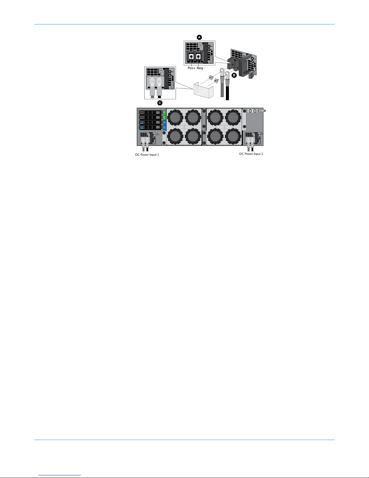
Attach the DC power cables (not included) from the DC power source to the DC power
supplies on the back of the firewall.
1. Remove the plastic DC power input cover from each of the two DC power supplies and then remove
the positive and negative terminal screws.
2. Crimp ring lugs to the ends of the DC cables. These lugs are used to connect the DC cables to the DC
inputs on the firewall.
3. Use the DC terminal screws to connect a positive (red) DC power cable to the positive terminal
on the first DC power supply and then connect a negative (black) DC power cable to the negative
terminal. Repeat this step for the second DC power supply using separate positive and negative
cables.
4. Replace the plastic covers over each DC power input.
5. Connect the two positive and two negative DC power cables to your power source, ensuring that you
observe the correct polarity (positive to positive and negative to negative).
28 PA-5200 SERIES NEXT-GEN FIREWALL HARDWARE REFERENCE | Connect Power to a PA-5200 Series
Firewall
©
2019 Palo Alto Networks, Inc.
STEP 5 |
After all DC power cables are securely connected, power on the DC power source.
PA-5200 SERIES NEXT-GEN FIREWALL HARDWARE REFERENCE | Connect Power to a PA-5200 Series Firewall 29
©
2019 Palo Alto Networks, Inc.

30 PA-5200 SERIES NEXT-GEN FIREWALL HARDWARE REFERENCE | Connect Power to a PA-5200 Series
Firewall

Service the PA-5200 Series Firewall
The following topics describe how to interpret the PA-5200 Series firewall status LEDs and
describes how to replace the serviceable components.
> Interpret the LEDs on a PA-5200 Series Firewall
> Replace the Air Intake Filters on a PA-5200 Series Firewall
> Replace a Fan Tray on a PA-5200 Series Firewall
> Replace a Power Supply on a PA-5200 Series Firewall
> Replace a Drive on a PA-5200 Series Firewall
31

32 PA-5200 SERIES NEXT-GEN FIREWALL HARDWARE REFERENCE | Service the PA-5200 Series Firewall
©
2019 Palo Alto Networks, Inc.

Interpret the LEDs on a PA-5200 Series
Firewall
The following table describes how to interpret the status LEDs on a PA-5200 Series firewall.
LED Description
Front Panel LEDs
PWR (Power) Green—The firewall is powered on.
Off—The firewall is not powered on or an error occurred with the internal
power system (for example, power is not within tolerance levels).
STS (Status) Green—The firewall is operating normally.
Yellow—The firewall is booting.
HA (High Availability) Green—The firewall is the active peer in an active/passive configuration.
Yellow—The firewall is the passive peer in an active/passive configuration.
Off—High availability (HA) is not operational on this firewall.
In an active/active configuration, the HA LED only
indicates HA status for the local firewall and has two
possible states (green or off); it does not indicate HA
connectivity of the peer. Green indicates that the firewall is
either active-primary or active-secondary and off indicates
that the firewall is in any other state (For example, nonfunctional or suspended).
TMP (Temperature) Green—The firewall temperature is normal.
Yellow—The firewall temperature is outside tolerance levels.
See PA-5200 Series Environmental Specifications for the temperature
range.
FANS Green—The fan trays and all fans are operating normally.
Red—One or more fans failed on one or both of the fan trays. To
determine which fan tray has a failure, check the system log or check the
LED on the fan trays.
PWR 1 and PWR 2 (Power) While facing the back of the firewall, power supply 1 (PWR 1) is on the left
and power supply 2 (PWR 2) is on the right.
Green—The power supply is functioning normally.
Red—Power supply is present but is not working.
ALM (Alarm) Red—A hardware component failed, such as a power supply failure, a
firewall failure that caused an HA failover, a drive failure, or hardware is
overheating and the temperature is above the high temperature threshold.
PA-5200 SERIES NEXT-GEN FIREWALL HARDWARE REFERENCE | Service the PA-5200 Series Firewall 33
©
2019 Palo Alto Networks, Inc.

LED Description
Off—The firewall is operating normally.
Ethernet Port LEDs
RJ-45 and AUX LEDs These ports have two LEDs.
• Left LED—Solid green indicates a network link.
• Right LED—Blinking green indicates network activity.
SFP, SFP+, and QSFP LEDs These ports have one green LED.
• Solid green indicates a network link.
• Blinking green indicates network activity.
Back Panel LEDs
Power supply The AC and DC power supplies have a FAIL and an OK LED.
• FAIL
• Solid yellow—The power supply failed. This can also indicate a fan
failure or overheating condition.
• Blinking yellow—The power supply is outside of tolerance levels.
• Off—Power supply is operating normally.
• OK
• Solid green—The power supply is operating normally.
• Blinking green—The power input is present but the power supply is
disabled by the system.
• Off—No power input or the power supply failed.
Fan tray Green—The fan trays and all fans are operating normally.
Red—One or more fans in the fan tray failed (see Replace a Fan Tray on a
PA-5200 Series Firewall).
34 PA-5200 SERIES NEXT-GEN FIREWALL HARDWARE REFERENCE | Service the PA-5200 Series Firewall
©
2019 Palo Alto Networks, Inc.

Replace the Air Intake Filters on a PA-5200
Series Firewall
The air intake filters are a critical part of the firewall cooling system. These filters ensures that air entering
the firewall does not contain debris. We recommend that you replace both filters (top and bottom) every six
months or less, depending on the environment where the firewall is located, to prevent a scenario where
there is not enough air passing through the filters to keep the firewall from overheating.
The firewall does not generate a system log indicating that an air filter has been removed or
that it needs to be replaced. Therefore, in addition to replacing them every six months (or
as needed), you need to schedule regular inspections and ensure that the filters do not clog
sooner than when they are due to be replaced. Do not attempt to clean and reuse a filter.
You can purchase replacement air filters and air filter covers from Palo Alto Networks or an authorized
reseller. The following procedure can be performed with the firewall powered on but do not leave the
firewall without the filters installed for longer than it takes to replace the filters.
STEP 1 |
STEP 2 |
Turn the two air filter cover thumb screws counter-clockwise and remove the filter cover and
filter (top filter shown).
Lift each side of the filter upward to loosen it from the filter cover and then slide the filter out
of the filter cover.
STEP 3 |
Install a new filter into the filter cover ensuring that you slide it under the filter cover cross
bars. You can install the filter with either side facing up.
PA-5200 SERIES NEXT-GEN FIREWALL HARDWARE REFERENCE | Service the PA-5200 Series Firewall 35
©
2019 Palo Alto Networks, Inc.

STEP 4 |
Replace the top filter cover and filter and turn the two thumb screws clockwise to secure the
cover to the firewall.
STEP 5 |
Repeat this procedure to replace the bottom air filter.
36 PA-5200 SERIES NEXT-GEN FIREWALL HARDWARE REFERENCE | Service the PA-5200 Series Firewall
©
2019 Palo Alto Networks, Inc.

Replace a Fan Tray on a PA-5200 Series
Firewall
PA-5200 Series firewalls have two fan trays and each fan tray contains four fans. If one fan on a fan tray
fails, the LED on the fan tray turns red. When this occurs, immediately replace the fan tray to avoid service
interruption. If two or more fans fail on one or both fan trays, the firewall will shut down and you must
replace the failed fan tray(s) to restore functionality.You can replace a fan tray while the firewall is powered
on but you must replace it within 45 seconds or the thermal protection circuit automatically shuts down the
firewall.
STEP 1 |
STEP 2 |
STEP 3 |
STEP 4 |
Remove the replacement fan tray from the packaging.
Identify the failed fan tray by viewing the LEDs.
During a failure condition, the fan tray LED on the failed fan tray and the FANS LED on the front of the
firewall show red.
Remove the failed fan tray.
1. Turn the two fan tray thumb screws counter-clockwise until the screws stop.
Earlier models will have four fan-tray thumb screws rather than two. The procedure for
both setups is the same.
2. Grasp the fan tray handle and pull the tray out of the firewall.
Slide the replacement fan tray into the empty fan-tray slot ensuring that the alignment grooves
on the fan tray and the fan-tray slot are aligned. Push the tray in until it seats and then turn the
four fan-tray thumb screws clockwise to secure the tray to the firewall.
The fan tray LED turns green and if there are no other failed fans, the FAN LED on the front of the
firewall turns green.
If the thermal protection circuit powered off the firewall due to overheating or fan failures, you need
to disconnect and reconnect power. On an AC model, disconnect both power cords, wait five seconds,
and then plug the cords back in. On a DC model, shut down the DC circuit that is providing power to the
firewall, wait five seconds, and then restore the power.
PA-5200 SERIES NEXT-GEN FIREWALL HARDWARE REFERENCE | Service the PA-5200 Series Firewall 37
©
2019 Palo Alto Networks, Inc.

Replace a Power Supply on a PA-5200 Series
Firewall
PA-5200 Series firewalls have either two AC or two DC power supplies (the second power supply is for
redundancy). If one power supply fails, you can replace it without service interruption as described in the
following procedures.
• Replace an AC Power Supply on a PA-5200 Series Firewall
• Replace a DC Power Supply on a PA-5200 Series Firewall
Replace an AC Power Supply on a PA-5200 Series Firewall
The following procedure describes how to replace an AC power supply.
To avoid injury to yourself or damage to your Palo Alto Networks® hardware or the data that
resides on the hardware, read the Product Safety Warnings.
STEP 1 |
STEP 2 |
STEP 3 |
STEP 4 |
Identify the failed power supply by viewing the power supply LED on the back of the firewall;
when there is a failure the FAIL LED turns solid yellow. For details on the power supply LEDS,
see Interpret the LEDs on a PA-5200 Series Firewall.
Remove the Velcro strap that secures the AC power cord to the power supply and remove the
power cord.
Grasp the handle on the failed power supply and then simultaneously press the release lever to
the left and then pull the power supply outward to remove it.
Remove the replacement power supply from the packaging and slide it into the empty power
supply slot. Push the power supply all the way in until the release lever clicks and secures the
power supply.
STEP 5 |
Connect the AC power cord to the power supply input and secure it to the power supply using
the Velcro strap.
38 PA-5200 SERIES NEXT-GEN FIREWALL HARDWARE REFERENCE | Service the PA-5200 Series Firewall
©
2019 Palo Alto Networks, Inc.

STEP 6 |
Connect the other end of the power cord to a grounded AC power source. The new power
supply automatically powers on, the OK LED turns green, the FAIL LED turns off, and the
power LED (PWR 1 or PWR 2) on the front of the firewall turns green.
Replace a DC Power Supply on a PA-5200 Series Firewall
The following procedure describes how to replace a DC power supply.
To avoid injury to yourself or damage to your Palo Alto Networks® hardware or the data that
resides on the hardware, read the Product Safety Warnings.
STEP 1 |
STEP 2 |
STEP 3 |
STEP 4 |
Identify the failed power supply by viewing the power supply LED on the back of the firewall;
when there is a failure, the FAIL LED on the failed power supply turns solid yellow. For more
details on the power supply LEDS, see Interpret the LEDs on a PA-5200 Series Firewall.
Power off the DC power source that is connected to the failed DC power supply.
Ensure that the power is off before continuing to the next step.
Remove the plastic cover that protects the DC input terminals and then use a Phillips-head
screwdriver to remove the screws holding the positive and negative DC cables to the DC input
terminals.
Grasp the handle on the failed power supply and then simultaneously press the release lever to
the left and pull the power supply outward to remove it.
STEP 5 |
Remove the replacement power supply from the packaging and slide it into the empty power
supply slot. Push the power supply all the way in until the release lever clicks and secures the
power supply.
PA-5200 SERIES NEXT-GEN FIREWALL HARDWARE REFERENCE | Service the PA-5200 Series Firewall 39
©
2019 Palo Alto Networks, Inc.

STEP 6 |
Reconnect the positive and negative DC power cables to the new power supply using the DC
terminal screws.
Make sure you establish the correct polarity: positive to positive and negative to negative.
STEP 7 |
When all DC power cables are securely connected and the plastic guard is properly reattached,
power on the DC power source.
40 PA-5200 SERIES NEXT-GEN FIREWALL HARDWARE REFERENCE | Service the PA-5200 Series Firewall
©
2019 Palo Alto Networks, Inc.

Replace a Drive on a PA-5200 Series Firewall
The PA-5200 Series firewalls have two solid-state drives (SSDs) used for system files and system logs and
two hard-disk drives (HDDs) used for network traffic log storage. Each drive pair is in a RAID 1 array so that
if a drive fails, you can replace the failed drive (using the same model drive) without service interruption.
The system drives are labeled SYS 1 and SYS 2 and the log drives are labeled LOG 1 and LOG 2.
When ordering a replacement drive from Palo Alto Networks or your reseller, you receive
two drives. This ensures that if the replacement drive is not the same model as the failed
drive, you can install two new matching drives. If the replacement drive model is the same as
the failed drive, you need only replace one failed drive and can store the second drive as a
spare. For firewalls in an HA pair, there is no requirement that the drive sizes match between
the paired systems.
The procedures to replace a system drive (SSD) and a log drive (HDD) are different.
• Replace a Log Drive on a PA-5200 Series Firewall
• Replace a System Drive on a PA-5200 Series Firewall
Replace a Log Drive on a PA-5200 Series Firewall
The following procedure describes how to replace a failed log drive. There are two scenarios: one where
the replacement drive is the same model as the failed drive and one where the replacement drive is not the
same model.
STEP 1 |
In a high availability (HA) configuration, if one log drive fails (or if both log drives fail) in the
active firewall, the firewall enters the non-functional HA state and fails over. If the firewall is
not in an HA configuration and one log drive fails, the firewall continues to operate. If both
log drives fail in a non-HA configuration, the firewall continues to operate but it does not log
network traffic and you cannot commit the configuration until there is at least one functioning
log drive.
Identify the failed drive and determine the drive model by running the following operational
command to view the status and model fields:
admin@PA-5020> show system raid detail
The following output shows that the Log1 drive failed and that the model number of that drive is
ST2000NX0253. The system log also shows an error that indicates which drive failed (Log1 or Log2).
Disk Pair Log Available
Status clean, degraded
Disk id Log1 Present
model : ST2000NX0253
size : 1907729 MB
status : failed
Disk id Log2 Present
model : ST2000NX0253
size : 1907729 MB
PA-5200 SERIES NEXT-GEN FIREWALL HARDWARE REFERENCE | Service the PA-5200 Series Firewall 41
©
2019 Palo Alto Networks, Inc.

status : active sync
STEP 2 |
STEP 3 |
STEP 4 |
Remove the failed drive from the RAID 1 array configuration. In this example, run the following
command to remove the Log1 drive from the array:
admin@PA-5020> request system raid remove log1
Press the ejector button on the drive carrier to release the carrier handle and gently pull the
handle toward you to remove the carrier and drive.
The illustration shows how to remove a system (SYS) drive. The procedure to remove a log drive is the
same.
Remove the replacement drive from the packaging and determine the drive model. You will
compare this model number with the model number of the failed drive to determine which
replacement procedure to use in 7.
STEP 5 |
STEP 6 |
Install the replacement drive in the drive carrier.
1. Remove the replacement drive from the antistatic bag and place it on an antistatic surface. Place the
failed drive next to the replacement drive with the connectors facing the same direction.
2. Remove the four screws that hold the failed drive in the carrier and remove the drive from the
carrier.
3. Install the replacement drive in the carrier and secure it using the four screws you removed from the
failed drive.
The illustration shows an SSD system drive and an HDD log drive; the procedure to swap the drive is the
same for both.
Install the carrier with the replacement drive:
1. Ensure that the drive carrier lever is in the open position; if it is not, press the ejector button on the
drive carrier to release the lever and pull it out until it is fully open.
42 PA-5200 SERIES NEXT-GEN FIREWALL HARDWARE REFERENCE | Service the PA-5200 Series Firewall
©
2019 Palo Alto Networks, Inc.

2. Slide the carrier assembly into the empty drive bay until it is about 1/4” (.64cm) from being fully
inserted.
3. Before fully inserting the carrier, ensure that the lever attaches to the locking mechanism on the
firewall and then close the lever to seat the carrier.
STEP 7 |
STEP 8 |
Choose from the following two installation procedures based on your findings in 4:
• If the replacement drive is the same model number as the failed drive, continue to 8.
• If the replacement drive is a different model number than the failed drive, continue to 9.
Same model replacement drive only) Add the replacement drive (that is the same model as the
failed drive) to the RAID 1 array:
1. Add the replacement drive to the RAID 1 array. In this example, run the following command to add
the LOG 1 drive to the array:
admin@PA-5020> request system raid add log1
If the replacement drive was previously used in a different Palo Alto Networks firewall,
include the force option in this command to force the system to reformat the drive and
add it to the array. If you reboot the firewall after removing the failed drive from the
array, the force option is not required. This is because the system will recognize that
a drive was missing and it will automatically reformat the newly inserted drive and will
add it to the array.
2. Periodically view the RAID status until you see that Disk Pair Log shows Available, the status
shows clean, and the status for each drive shows active sync status. To view RAID status, run
the following command:
admin@PA-5020> show system raid detail
STEP 9 |
The following output shows that both log drives are in the active sync state:
Disk Pair Log Available
Status clean
Disk id Log1 Present
model : ST2000NX0253
size : 1907729 MB
status : active sync
Disk id Log2 Present
model : ST2000NX0253
size : 1907729 MB
status : active sync
Different model replacement drive only) Add the replacement drive (that is a different model
than the failed drive) to the RAID 1 array:
When you initiate the copy command as described in the following steps, logging stops
and you cannot view logs until the copy is complete and the disk pair shows Available.
1. (Optional) Suspend the firewall with the failed drive if it is the active firewall in an HA configuration.
PA-5200 SERIES NEXT-GEN FIREWALL HARDWARE REFERENCE | Service the PA-5200 Series Firewall 43
©
2019 Palo Alto Networks, Inc.

The firewall will fail over when the copy process in this procedures starts but you can
choose to Verify Failover or manually suspend the firewall with the failed drive before
you continue.
2. Copy the data from the other drive in the RAID 1 array to the replacement drive. In this example, run
the following command to copy the data from the Log2 drive to the Log1 drive:
admin@PA-5020> request system raid copy from log2 to log1
3. Run the following CLI command to view the status of the copy:
admin@PA-5020> show system raid detail
Periodically run this command until the copy is complete and the Disk Pair Log shows
Available.
At this point, the Log2 drive shows not in use because the drive models are not
the same.
Disk Pair Log Available
Status clean, degraded
Disk id Log1 Present
model : ST2000NX0999
size : 1907729 MB
status : active sync
Disk id Log2 Present
model : ST2000NX0253
size : 1907729 MB
status : not in use
4. Replace the other drive in the array so the drive models in the array are the same. In this example,
physically remove the Log2 drive, remove it from the carrier, and then install the second replacement
drive in the carrier. 9.e shows how to swap drives in a carrier.
5. Add the second replacement drive to the RAID 1 array. In this example, run the following command
to add the Log2 drive to the array:
admin@PA-5020> request system raid add log2
The system automatically starts to configure the new drive to mirror the other drive in the RAID 1
array.
6. Periodically view the RAID status until you see that the Disk Pair Log shows Available and
both drives show active sync status. To view RAID status, run the following command:
admin@PA-5020> show system raid detail
The following output shows that both drives are in the active sync state:
Disk Pair Log Available
Status clean
Disk id Log1 Present
model : ST2000NX0999
44 PA-5200 SERIES NEXT-GEN FIREWALL HARDWARE REFERENCE | Service the PA-5200 Series Firewall
©
2019 Palo Alto Networks, Inc.

size : 1907729 MB
status : active sync
Disk id Log2 Present
model : ST2000NX0999
size : 1907729 MB
status : active sync
Replace a System Drive on a PA-5200 Series Firewall
The following procedure describes how to replace a failed system drive. There are two scenarios: one where
the replacement drive is the same model as the failed drive and one where the replacement drive is not the
same model.
If you replace a system drive with a different model drive, you must boot the firewall into the
Maintenance Recovery Tool (MRT) to copy data between drives. In a high availability (HA)
configuration, suspend the firewall with the failed drive as described in this procedure.
In a high availability (HA) configuration, if one system drive fails (or if both system drives
fail) in the active firewall, the firewall enters the non-functional HA state and fails over. If
the firewall is not in an HA configuration and one system drive fails, the firewall continues
to operate. If both system drives fail in a non-HA configuration, you will need to replace the
systems drives and restore the firewall configuration from a recent configuration backup.
STEP 1 |
Identify the failed drive and determine the drive model.
When the system drives are functioning normally, all system drive partitions show both drives with the
status clean. If a system drive fails, the Overall System Drives RAID status shows degraded,
one or more failed partition array shows clean, degraded, and one of the drives will be missing (Sys1
or Sys2).In this example, the output from the show system raid detail command shows that the
drive model is MICRON_M510DC_MT, the panlogs partition shows the status clean, degraded, and
drive Sys1 is missing from the panlogs array; together, these indicate that you need to replace the Sys1
drive.
admin@PA-5220> show system raid detail
Overall System Drives RAID status degraded
-----------------------------------------------------------------------------
Drive status
Disk id Sys1 Present (MICRON_M510DC_MT)
Disk id Sys2 Present (MICRON_M510DC_MT)
-----------------------------------------------------------------------------
Partition status
panlogs clean, degraded
Drive id Sys2 active sync
maint clean
Drive id Sys1 active sync
Drive id Sys2 active sync
sysroot0 clean
Drive id Sys1 active sync
Drive id Sys2 active sync
sysroot1 clean
Drive id Sys1 active sync
Drive id Sys2 active sync
pancfg clean
PA-5200 SERIES NEXT-GEN FIREWALL HARDWARE REFERENCE | Service the PA-5200 Series Firewall 45
©
2019 Palo Alto Networks, Inc.

Drive id Sys1 active sync
Drive id Sys2 active sync
panrepo clean
Drive id Sys1 active sync
Drive id Sys2 active sync
swap clean
Drive id Sys1 active sync
Drive id Sys2 active sync
STEP 2 |
STEP 3 |
Remove the failed drive from the RAID 1 array. In this example, run the following command to
remove drive Sys1 from the array:
admin@PA-5020> request system raid remove sys1
Confirm that the failed drive is removed from all partitions. In the following output of the show
system raid detail, you see that drive id Sys1 is now missing from all partitions.
admin@PA-5220> show system raid detail
Overall System Drives RAID status degraded
-----------------------------------------------------------------------------
Drive status
Disk id Sys1 Present (MICRON_M510DC_MT)
Disk id Sys2 Present (MICRON_M510DC_MT)
-----------------------------------------------------------------------------
Partition status
panlogs clean, degraded
Drive id Sys2 active sync
maint clean, degraded
Drive id Sys2 active sync
sysroot0 clean, degraded
Drive id Sys2 active sync
sysroot1 clean, degraded
Drive id Sys2 active sync
pancfg clean, degraded
Drive id Sys2 active sync
panrepo clean, degraded
Drive id Sys2 active sync
swap clean, degraded
Drive id Sys2 active sync
STEP 4 |
Press the ejector button on the drive carrier to release the carrier handle and gently pull the
handle toward you to remove the carrier and drive.
46 PA-5200 SERIES NEXT-GEN FIREWALL HARDWARE REFERENCE | Service the PA-5200 Series Firewall
©
2019 Palo Alto Networks, Inc.

STEP 5 |
Remove the replacement drive from the packaging, determine the drive model, and place it on
an antistatic surface. Then compare this model number with the model number of the failed
drive to determine which replacement procedure to use in 7.
STEP 6 |
STEP 7 |
Install the replacement drive in the drive carrier.
1. Place the failed drive next to the replacement drive with the connectors facing the same direction.
2. Remove the four screws that hold the failed drive in the carrier and remove the drive from the
carrier.
3. Install the replacement drive in the carrier and secure it using the four screws you removed from the
failed drive.
The illustration shows an SSD system drive and an HDD log drive; the procedure to swap the drive is
the same for both.
Install the replacement drive in the firewall.
1. Ensure that the drive carrier lever is in the open position; if it is not, press the ejector button on the
drive carrier to release the lever and pull it out until it is fully open.
2. Slide the replacement drive and carrier assembly into the empty drive bay until it is about 1/4” (.6cm)
from being fully inserted.
3. Before fully inserting the drive carrier, ensure that the lever attaches to the locking mechanism on the
firewall and then close the lever to seat the carrier.
STEP 8 |
STEP 9 |
Choose from the following two installation procedures based on your findings in 5:
• If the replacement drive is the same model number as the failed drive, continue to 9.
• If the replacement drive is a different model number than the failed drive, skip to 10.
Same model replacement drive only) Add the replacement drive (one that is the same model as
the failed drive) to the RAID 1 array:
1. Add the replacement drive to the RAID 1 array. In this example, run the following command to add
the SYS 1 drive to the array:
admin@PA-5020> request system raid add sys1
If the replacement drive was previously used in a different Palo Alto Networks firewall,
include the force option in this command to force the system to reformat the drive
and add it to the array. If you reboot the firewall after removing the failed drive from
the array, the force option is not required. Because the firewall recognizes that a drive
is missing and it will automatically reformat the newly inserted drive and adds it to the
array.
PA-5200 SERIES NEXT-GEN FIREWALL HARDWARE REFERENCE | Service the PA-5200 Series Firewall 47
©
2019 Palo Alto Networks, Inc.

2. Periodically view the RAID status until you see that the Overall System Drives RAID status
shows Good, all partitions show clean, and both drives show active sync. To view RAID status,
run the following command:
admin@PA-5020> show system raid detail
Do not reboot the firewall until all partitions are ready; otherwise, the system drives
may become out of sync and the firewall will not boot.
Overall System Drives RAID status Good
--------------------------------------------------------------------------Drive status
Disk id Sys1 Present (MICRON_M510DC_MT)
Disk id Sys2 Present (MICRON_M510DC_MT)
--------------------------------------------------------------------------Partition status
panlogs clean
Drive id Sys1 active sync
Drive id Sys2 active sync
maint clean
Drive id Sys1 active sync
Drive id Sys2 active sync
sysroot0 clean
Drive id Sys1 active sync
Drive id Sys2 active sync
sysroot1 clean
Drive id Sys1 active sync
Drive id Sys2 active sync
pancfg clean
Drive id Sys1 active sync
Drive id Sys2 active sync
panrepo clean
Drive id Sys1 active sync
Drive id Sys2 active sync
swap clean
Drive id Sys1 active sync
Drive id Sys2 active sync
STEP 10 |
Different model replacement drive only) Add the replacement drive (one that is a different
model than the failed drive) to the RAID 1 array:
1. Connect a serial cable from your computer to the Console port on the firewall and connect to the
firewall using terminal emulation software that is configured to use 9600-8-N-1 settings.
2. (Optional) Suspend the firewall with the failed drive if it is the active firewall in an HA configuration.
The firewall fails over when you boot into the Maintenance Recover Tool (MRT) as
described in the following step but you can choose to Verify Failover or manually
suspend the firewall that contains the failed drive.
3. Reboot the firewall with the failed drive into the MRT by running the following command:
admin@PA-5020> debug system maintenance-mode
4. Press Enter on CONTINUE and then navigate to RAID and press Enter again.
48 PA-5200 SERIES NEXT-GEN FIREWALL HARDWARE REFERENCE | Service the PA-5200 Series Firewall
©
2019 Palo Alto Networks, Inc.

5. Navigate to the Migrate Drive section and select the drive to migrate. In this example, select
Migrate drive Sys2 -> Sys1 to initiate the process of copying the system data from the Sys2
drive to the Sys1 replacement drive.
6. After migration is complete, remove the other system drive. In this example, remove the Sys2 drive.
7. Press Esc to go back to the main menu and then press Enter on Reboot.
8. After the firewall boots PAN-OS, replace the other drive in the array so the drives in the array are
the same model. In this example, first remove the Sys2 drive from the carrier and install the second
replacement drive (one that is the same model as Sys1) into the carrier (see 6). Then, install the
second replacement drive in slot Sys 2.
9. Add the second replacement drive to the RAID 1 array. In this example, run the following command
to add drive Sys2 to the array
admin@PA-5020> request system raid add sys2
If the replacement drive was previously used as a system drive in a different Palo
Alto Networks firewall, include the force option in this command to force the system
to reformat the drive and add it to the array. If you reboot the firewall after removing
the failed drive from the array, the force option is not required. Because the firewall
recognizes that a system drive is missing and automatically reformats the newly
inserted drive and adds it to the array.
The system automatically starts to configure the new drive to mirror the other drive in the RAID 1
array.
10.Periodically view the RAID status until you see that the Overall System Drives RAID status
shows Good, all partitions show clean, and both drives show active sync. To view RAID status,
run the following command:
admin@PA-5020> show system raid detail
Do not reboot the firewall until all partitions are ready; otherwise, the system drives
may become out of sync and the firewall will not boot.
Overall System Drives RAID status Good
--------------------------------------------------------------------------Drive status
Disk id Sys1 Present (MICRON_M510DC_MT)
Disk id Sys2 Present (MICRON_M510DC_MT)
--------------------------------------------------------------------------Partition status
panlogs clean
Drive id Sys1 active sync
Drive id Sys2 active sync
maint clean
Drive id Sys1 active sync
Drive id Sys2 active sync
sysroot0 clean
Drive id Sys1 active sync
Drive id Sys2 active sync
sysroot1 clean
Drive id Sys1 active sync
Drive id Sys2 active sync
pancfg clean
Drive id Sys1 active sync
Drive id Sys2 active sync
panrepo clean
PA-5200 SERIES NEXT-GEN FIREWALL HARDWARE REFERENCE | Service the PA-5200 Series Firewall 49
©
2019 Palo Alto Networks, Inc.

Drive id Sys1 active sync
Drive id Sys2 active sync
swap clean
Drive id Sys1 active sync
Drive id Sys2 active sync
50 PA-5200 SERIES NEXT-GEN FIREWALL HARDWARE REFERENCE | Service the PA-5200 Series Firewall

PA-5200 Series Firewall Specifications
The following topics describe the PA-5200 Series firewall hardware specifications. For feature,
capacity, and performance information, refer to the PA-5200 Series firewall datasheet.
> PA-5200 Series Physical Specifications
> PA-5200 Series Electrical Specifications
> PA-5200 Series Environmental Specifications
> PA-5200 Series Miscellaneous Specifications
51

52 PA-5200 SERIES NEXT-GEN FIREWALL HARDWARE REFERENCE | PA-5200 Series Firewall
Specifications
©
2019 Palo Alto Networks, Inc.

PA-5200 Series Physical Specifications
The following table describes PA-5200 Series firewall physical specifications.
The physical specifications are identical for all PA-5200 Series models (PA-5220, PA-5250,
PA-5260, and PA-5280 firewalls).
Specification Value
Rack units and dimensions Rack units—3U
Dimensions—5.25”H X 21”D X 17.25”W (13.33cm X 52.07cm
X 43.81cm)
The depth dimension includes hardware that
protrudes from the back of the firewall.
Weight • Firewall weight—46lbs (20.87Kg)
• Shipping weight—62lbs (28.13Kg)
PA-5200 SERIES NEXT-GEN FIREWALL HARDWARE REFERENCE | PA-5200 Series Firewall Specifications 53
©
2019 Palo Alto Networks, Inc.

PA-5200 Series Electrical Specifications
The following table describes PA-5200 Series firewall electrical specifications.
Specification Value
Power supplies Two 1200W AC or DC power supplies; the second
power supply is for redundancy.
Input voltage • AC power supplies—100-240VAC (50-60Hz)
• DC power supplies—-40 to -60VDC
Power consumption (AC or DC) 870W
Maximum current consumption • AC power supplies—8.5A@100VAC, 3.6A@240VAC
• DC power supplies—19A@-40VDC, 12.7A@-60VDC
Maximum inrush current The following values include both power supplies.
• AC power supplies—50A@230VAC, 50A@120VAC
• DC power supplies—200A@72VDC
54 PA-5200 SERIES NEXT-GEN FIREWALL HARDWARE REFERENCE | PA-5200 Series Firewall
Specifications
©
2019 Palo Alto Networks, Inc.

PA-5200 Series Environmental Specifications
The following table describes the PA-5200 Series firewall environmental specifications.
Specification Value
Operating temperature range 32°F to 122°F (0°C to 50°C)
Non-operating temperature -4°F to 158°F (-20°C to 70°C)
Humidity tolerance 5% to 90% non-condensing
Airflow Front-to-back
Maximum BTUs/hour 2,970 BTUs/hour
Electromagnetic Interference (EMI) FCC Class A, CE Class A, VCCI Class A
Acoustic noise Tested in bystander position (ISO 7779)
• AC Power Supplies
• Average—73 dB(A)
• Maximum—86 dB(A)
• DC Power Supplies
• Average—67 dB(A)
• Maximum—86 dB(A)
Maximum operating altitude 10,000ft (3,048m)
PA-5200 SERIES NEXT-GEN FIREWALL HARDWARE REFERENCE | PA-5200 Series Firewall Specifications 55
©
2019 Palo Alto Networks, Inc.

PA-5200 Series Miscellaneous Specifications
The following table describes the PA-5200 Series firewall miscellaneous specifications.
Specification Value
Mean time between failures (MTBF) 9 years
Sotrage Capacity • System file storage—240GB (Two 240GB solid-state
drives (SSDs) in a RAID-1 pair).
• Log storage—2TBs (Two 2TB hard disk drives (HDDs) in
a RAID-1 pair).
56 PA-5200 SERIES NEXT-GEN FIREWALL HARDWARE REFERENCE | PA-5200 Series Firewall
Specifications

PA-5200 Series Firewall Compliance
Statements Overview
Palo Alto Networks obtains regulatory compliance certifications to comply with the laws and
regulations in each country where there are requirements applicable to our products. Our
products meet standards for product safety and electromagnetic compatibility when used for
their intended purpose.To view compliance statements for the PA-3200 Series firewalls, see
PA-5200 Series Firewall Compliance Statements.
57

58 PA-5200 SERIES NEXT-GEN FIREWALL HARDWARE REFERENCE | PA-5200 Series Firewall Compliance
Statements Overview
©
2019 Palo Alto Networks, Inc.

PA-5200 Series Firewall Compliance
Statements
The following lists the PA-5200 Series firewall hardware compliance statements:
• VCCI
This section provides the compliance statement for the Voluntary Control Council for Interference by
Information Technology Equipment (VCCI), which governs radio frequency emissions in Japan.
The following information is in accordance to VCCI Class A requirements:
Translation: This is a Class A product. In a domestic environment this product may cause radio
interference, in which case the user may be required to take corrective actions.
• NEBS Requirements
The following lists the Network Equipment Building System (NEBS) requirements for PA-5200 Series
firewalls.
• The firewall is intended to be installed in a Network Telecommunication Facility (Central Office) as
part of a Common Bonding Network (CBN) or Isolated Bonding Network (IBN). Bare conductors
must be coated with an appropriate antioxidant compound before crimp connections are made. All
unplated connectors, braided strap, and bus bars must be brought to a bright finish and then coated
with an antioxidant before they are connected.
Fastening hardware must be compatible with the materials being joined and must preclude loosening,
deterioration, and electrochemical corrosion of the hardware and the joined materials.
• The firewall is suitable for connection to the Central Office or Customer Premise Equipment (CPE).
• The DC battery return wiring on the firewall must be connected as an isolated DC return (DC-I).
The intra-building ports (RJ-45 Ethernet ports, AUX ports, HA ports, and the MGT
port) of the equipment or subassembly are suitable for connection to only intrabuilding or unexposed wiring or cabling. The intrabuilding port(s) of the equipment
or subassembly must not be metallically connected to interfaces that connect to the
Outside Plant (OSP) or its wiring. These interfaces are designed for use as intrabuilding interfaces only (Type 2 or Type 4 ports as described in GR-1089-CORE,
Issue 6) and require isolation from the exposed OSP cabling. The addition of primary
protectors is not sufficient protection to connect these interfaces metallically to OSP
wiring.The firewall must be connected to an external Special Protection Device (SPD)
when installed and connected to commercial AC power.
The firewall must be connected to an external Special Protection Device (SPD) when
installed and connected to commercial AC power.
• BSMI EMC Statement—User warning: This is a Class A product. When used in a residential environment
it may cause radio interference. In this case, the user will be required to take adequate measures.
• Manufacturer—Flextronics International.
• Country of Origin—Made in the USA with parts of domestic and foreign origin.
PA-5200 SERIES NEXT-GEN FIREWALL HARDWARE REFERENCE | PA-5200 Series Firewall Compliance Statements
Overview 59
©
2019 Palo Alto Networks, Inc.

60 PA-5200 SERIES NEXT-GEN FIREWALL HARDWARE REFERENCE | PA-5200 Series Firewall Compliance
Statements Overview
 Loading...