

Palmer WT PB 40 User manual

USER´S MANUAL
BEDIENUNGSANLEITUNG
MANUEL D´UTILISATION
MANUAL DE USUARIO
INSTRUKCJA OBSŁUGI
MANUALE D´USO
WTP B40
POWERBAR – POWER SUPPLY
WITH 8 OUTPUTS FOR PEDALBAY 40
PWTPB40

CONTENTS / INHALTSVERZEICHNIS / CONTENU /
CONTENIDO /TREŚĆ / CONTENUTO
ENGLISH
SAFETY INFORMATION 3
INTRODUCTION 5
CONNECTIONS, OPERATING AND
DISPLAY ELEMENTS 5
INSTALLATION 6
TECHNICAL DATA 7
MANUFACTURER’S DECLARATIONS 8
DEUTSCH
SICHERHEITSHINWEISE 9
EINFÜHRUNG 11
ANSCHLÜSSE, BEDIEN- UND ANZEIGEELEMENTE 11
MONTAGE 12
TECHNISCHE DATEN 13
HERSTELLERERKLÄRUNGEN 14
FRANCAIS
MESURES PRÉVENTIVES 15
INTRODUCTION 17
RACCORDEMENTS, ÉLÉMENTS DE COMMANDE
ET D’AFFICHAGE 17
MONTAGE 18
CARACTÉRISTIQUES TECHNIQUES 19
DÉCLARATIONS DU FABRICANT 20
ESPAÑOL
MEDIDAS DE SEGURIDAD 21
INTRODUCCIÓN 23
CONEXIONES, ELEMENTOS DE MANEJO Y
ELEMENTOS DE VISUALIZACIÓN 23
MONTAJE 24
DATOS TÉCNICOS 25
DECLARACIONES DEL FABRICANTE 26
POLSKI
ŚRODKI OSTROŻNOŚCI 27
WPROWADZENIE 29
PRZYŁĄCZA, ELEMENTY OBSŁUGI I WSKAŹNIKI 29
MONTAŻ 30
DANE TECHNICZNE 31
OŚWIADCZENIA PRODUCENTA 32
ITALIANO
MISURE PRECAUZIONALI 33
INTRODUZIONE 35
CONNETTORI, ELEMENTI DI COMANDO E
DI VISUALIZZAZIONE 35
MONTAGGIO 36
DATI TECNICI 37
DICHIARAZIONI DEL PRODUTTORE 38

ENGLISH
YOU‘VE MADE THE RIGHT CHOICE!
We have designed this product to operate reliably over many years. Palmer
and many years of experience as a manufacturer of high-quality audio products. Please read this User‘s
Manual carefully, so that you can begin making optimum use of your Palmer
You can nd more information about Palmer
®
at our Internet site www.palmer-germany.com.
®
stands for this with its name
®
product quickly.
SAFETY INFORMATION
1. Please read these instructions carefully.
2. Keep all information and instructions in a safe place.
3. Follow the instructions.
4. Observe all safety warnings. Never remove safety warnings or other information from the equipment.
5. Use the equipment only in the intended manner and for the intended purpose.
6. Use only suiciently stable and compatible stands and/or mounts (for xed installations). Make certain
that wall mounts are properly installed and secured. Make certain that the equipment is installed securely
and cannot fall down.
7. During installation, observ e the applicable safety regulations for your country.
8. Never install and operate the equipment near radiators, heat registers, ovens or other sources of heat.
Make certain that the equipment is always installed so that is cooled suiciently and cannot overheat.
9. Never place sources of ignition, e.g., burning candles, on the equipment.
10. Ventilation slits must not be blocked.
11. Keep a minimum distance of 20 cm around and above the device.
12. Do not use this equipment in the immediate vicinity of water (does not apply to special outdoor
equipment - in this case, observe the special instructions noted below. Do not expose this equipment to
ammable materials, uids or gases. Avoid direct sunlight!
13. Make certain that dripping or splashed water cannot enter the equipment. Do not place containers
lled with liquids, such as vases or drinking vessels, on the equipment.
14. Make certain that objects cannot fall into the device.
15. Use this equipment only with the accessories recommended and intended by the manufacturer.
16. Do not open or modify this equipment.
17. After connecting the equipment, check all cables in order to prevent damage or accidents, e.g.,
due to tripping hazards.
18. During transport, make certain that the equipment cannot fall down and possibly cause property
damage and personal injuries.
19. If your equipment is no longer functioning properly, if uids or objects have gotten inside the equipment
or if it has been damaged in anot her way, switch it o immediately and unplug it from the mains outlet
(if it is a powered device). This equipment may only be repaired by authorized, qualied personnel.
20. Clean the equipment using a dry cloth.
21. Comply with all applicable disposal laws in your country. During disposal of packaging, please separate
plastic and paper/cardboard.
22. Plastic bags must be kept out of reach of children.
23. Please note that changes or modications not expressly approved by the party responsible for compliance
could void the user´s authority to operate the equipment.
FOR EQUIPMENT THAT CONNECTS TO THE POWER MAINS
24. CAUTION: If the power cord of the device is equipped with an earthing contact, then it must be
connected to an outlet with a protective ground. Never deactivate the protective ground of a power cord.
25. If the equipment has been exposed to strong uctuations in temperature (for example, after transport),
do not switch it on immediately. Moisture and condensation could damage the equipment. Do not switch
on the equipment until it has reached room temperature.
26. Before connecting the equipment to the power outlet, rst verify that the mains voltage and frequency
match the values specied on the equipment. If the equipment has a voltage selection switch, connect
the equipment to the power outlet only if the equipment values and the mains power values match. If the
included power cord or power adapter does not t in your wall outlet, contact your electrician.
27. Do not step on the power cord. Make certain that the power cable does not become kinked, especially
at the mains outlet and/or power adapter and the equipment connector.
28. When connecting the equipment, make certain that the power cord or power adapter is always freely
accessible. Always disconnect the equipment from the power supply if the equipment is not in use or if you
want to clean the equipment. Always unplug the power cord and power adapter from the power outlet at
the plug or adapter and not by pulling on the cord. Never touch the power cord and power adapter with
wet hands.
29. Whenever possible, avoid switching the equipment on and o in quick succession because otherwise
this can shorten the useful life of the equipment.
ENGLISH
DEUTSCHFRANCAIS
ESPAÑOL
ITALIANO POLSKI
3
30. IMPORTANT INFORMATION: Replace fuses only with fuses of the same type and rating. If a fuse blows
repeatedly, please contact an authorised service centre.
31. To disconnect the equipment from the power mains completely, unplug the power cord or power
adapter from the power outlet.
32. If your device is equipped with a Volex power connector, the mating Volex equipment connector
must be unlocked before it can be removed. However, this also means that the equipment can slide and
fall down if the power cable is pulled, which can lead to personal injuries and/or other damage. For this
reason, always be careful when laying cables.
33. Unplug the power cord and power adapter from the power outlet if there is a risk of a lightning strike or
before extended periods of disuse.
34. The appliance is not to be used by persons (including children) with reduced physical, sensory or mental
DEUTSCHENGLISH
capabilities, or lack of experience and knowledge.
35. Children must be instructed not to play with the device.
36. If the power cord of the device is damaged, do not use the device. The power cord must be replaced
by an adequate cable or assembly from an authorized service center.
CAUTION:
To reduce the risk of electric shock, do not remove cover (or back). There
are no user serviceable parts inside. Maintenance and repairs should be
FRANCAIS
The warning triangle with lightning symbol indicates dangerous uninsulated voltage inside the
unit, which may cause an electrical shock.
The warning triangle with exclamation mark indicates important operating and maintenance
instructions.
exclusively carried out by qualied service personnel.
ESPAÑOL
POLSKI
ITALIANO
Warning! This symbol indicates a hot surface. Certain parts of the housing can become hot
during operation. After use, wait for a cool-down period of at least 10 minutes before handling or
transporting the device.
Warning! This device is designed for use below 2000 metres in altitude.
Warning! This product is not intended for use in tropical climates.
4
INTRODUCTION
PANTONE Warm Gray 8C
PANTONE Warm Gray 8C
The regulated Palmer Universal power supply unit for the Palmer PEDALBAY 40 oers 8 low-voltage outputs
for powering guitar and bass guitar eects devices. Built into the pedalboard, it oers convenient and
organised wiring, and looks tidy. Even during transport, eects devices can remain wired thanks to the
special metal guard strip that protects connected low-voltage wires against damage and unintended
removal. Four attachment points in the metal section are positioned to facilitate permanent and secure
attachment of the wires with cable ties. A suicient number of low-voltage wires with standard 2.1 x 5.5 mm
coaxial power connectors are included.
CONNECTIONS, OPERATING AND DISPLAY ELEMENTS
3
2
1
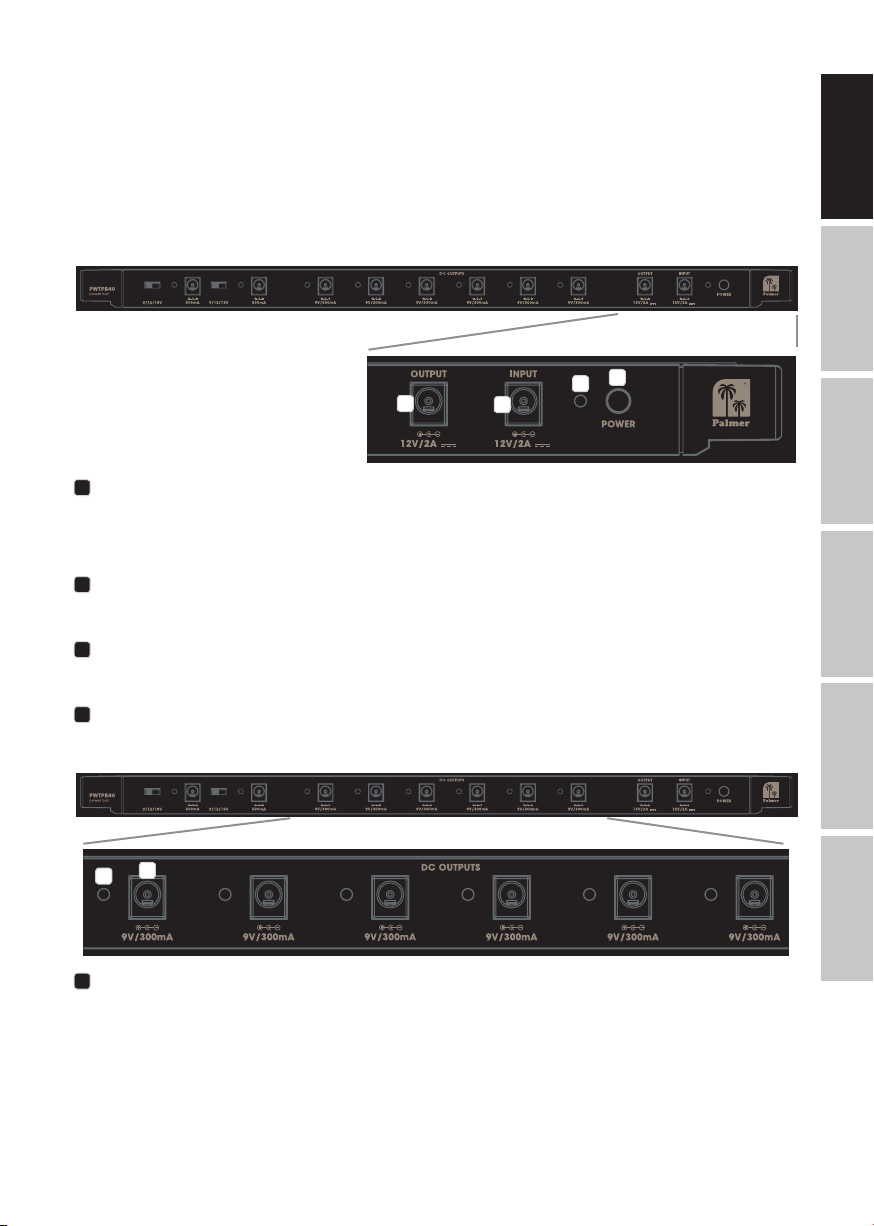
INPUT
Low-voltage connector for supplying power to the power supply unit (12 V DC / 2 A, outside: positive).
Please use only the provided power adapter, to protect the power supply unit from damage and to ensure
suicient and safe power supply for all connected eects devices.
2
OUTPUT
Low-voltage connector for forwarding the power supply connected to the INPUT socket.
1
4
ENGLISH
DEUTSCHFRANCAIS
3
POWER
Device ON/OFF button.
4
POWER LED
The POWER LED lights up as soon as the device is correctly connected to the power supply and
switched on.
5
6
5
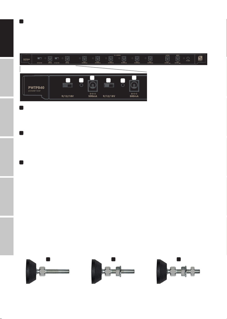
DC OUTPUTS
Six low-voltage connectors, each with a 9 V DC and maximum 300 mA current for connecting eects devices
with the corresponding load values (9 V DC / outside: positive / up to 300 mA).
ESPAÑOL
ITALIANO POLSKI
5
6
PANTONE Warm Gray 8C
PANTONE Warm Gray 8C
DISPLAY LEDS
Located next to the sockets, two-tone LEDs for displaying the status of the corresponding DC output. The
LEDs light up green to signal correct functioning and turn red in the event of a malfunction (short circuit). In
the event of a DC output malfunction, remove the connected low-voltage cable and corresponding eects
device, and check both for short circuiting. Once the source of the malfunction has been removed, the DC
output is ready for operation again. Unaected DC outputs remain operational even during a malfunction
at one of the other DC outputs.
DEUTSCHENGLISH
8 9
7
8
7
9
FRANCAIS
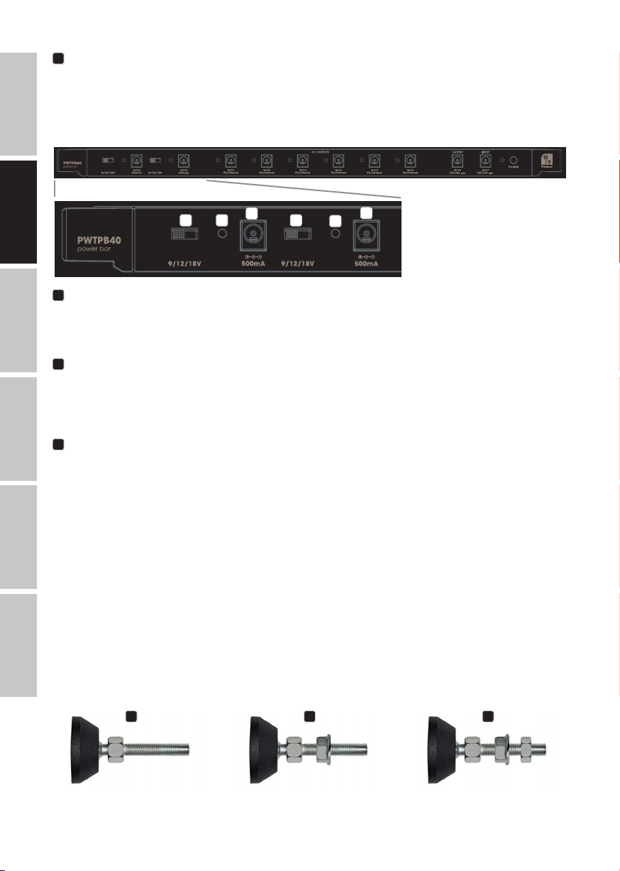
7
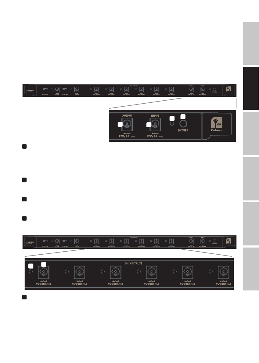
DC OUTPUTS
Two low-voltage connectors with a separately switchable output voltage and maximum 500 mA current for
connecting eects devices with the corresponding load values (9 V / 12 V / 18 V DC / outside: positive / up
to 500 mA).
8
SWITCH 9 / 12 / 18 V
3-way switch for switching the output voltage for low-voltage socket no. 7. Move the switch to the desired
position: 9 V left, 12 V middle or 18 V right. Ensure that the output voltage corresponds to the connection
ESPAÑOL
value of the relevant eects device, and switch the device on only after having adjusted the output
voltage accordingly.
9
DISPLAY LEDS
Located next to the sockets, two-tone LEDs for displaying the status of the corresponding DC output. The
LEDs light up green to signal correct functioning and turn red in the event of a malfunction (short circuit).
In the event of a DC output malfunction, remove the connected low-voltage cable and corresponding
eects device, and check both for short circuiting. Once the source of the malfunction has been removed,
the DC output is ready for operation again. Unaected DC outputs remain operational even during a
POLSKI
malfunction at one of the other DC outputs.
INSTALLATION
Installation on a pedalboard is possible anywhere where a cross bar is present. Remove the cross bar where
the power supply unit is to be installed, and install the unit there. When installing on the upper edge of the
pedalboard, use an appropriate tool to remove both adjustable articulated feet with M8 threads, and take
ITALIANO
out the cross bar attached to the frame. Place one of the supplied M8 nuts in each of the appropriate
recesses on the shorter side of the power supply unit, and simultaneously guide both sides (with the Velcro
tape on the upper side) into the frame’s U-shaped prole. In order to be able to attach the L-shaped metal
strip to the adjustable articulated feet, unscrew the M8 nuts on the articulated feet (A), screw on a supplied
M8 ange nut with the ange facing the open end (B) and then screw on the previously removed M8 nut (C).
6
A B C

Use the articulated feet to screw the power supply unit to the frame, locking it into place with the standard
M8 nut (D). Now place the L-shaped guard strip on the standard M8 nuts (E) and secure it with the M8
ange nuts (F). For technical reasons, the guard strip may only be positioned on the upper side of the
pedalboard.
Positioning the power supply unit elsewhere rst requires removal of the cross bar on the upper or lower
edge in order to be able to remove the desired cross bar. Once this has been removed from the frame,
place one of the supplied M6 nuts in each of the appropriate recesses on the shorter side of the power
supply unit and simultaneously guide both sides (with the Velcro tape on the upper side) into the frame’s
U-shaped prole. Now screw the power supply unit in with the previously removed M6 socket screw.
ENGLISH
D E F
TECHNICAL DATA
Product number: PWTPB40
Product type: Low-voltage power distributor
Type: Power distributor for Palmer PEDALBAY 40
Total outputs: 8 (6x 9 V DC, 2x switchable 9/12/18 V DC) + 1x for forwarding
Output connections: 2.1 x 5.5 mm low-voltage sockets
Output voltage: 9 V DC or 9/12/18 V DC, outside: positive
Output current: Maximum 2 A
Total inputs: 1
Input connections: 2.1 x 5.5 mm low-voltage socket
Controls: On/O switch, 2x voltage switches 9/12/18 V
Display elements: Power LED, 8x status two-tone LEDs
Power supply: External power supply, primary voltage 100 –240 V AC/50–60 Hz
Operating voltage: 12 V DC, 2 A, outside: positive
Protective circuitry: Short circuiting and overloading for each output
Ambient temperature
(in operation):
Relative air humidity: <80%, non-condensing
Housing material: Aluminum
Housing nish: Powder coated/anodised
Housing color: Black
Dimensions (W x H x D): 450 x 24 x 50 mm
Weight: 0.65 kg
Accessories included: External power supply with 1.5 m cable, 9x DC cables, 60 cm, with
input voltage
(normal operation = green, error = red)
0° to 40°C
coaxial power connectors straight to angled, 5x DC cables, 16 cm,
with coaxial power connectors straight to angled, 2x M6 + 2x M8
nuts, 2x M8 ange nuts, Velcro tape, L-shaped guard strip and
4 attachment points for cable ties
DEUTSCHFRANCAIS
ESPAÑOL
ITALIANO POLSKI
7

MANUFACTURER´S DECLARATIONS
MANUFACTURER‘S WARRANTY & LIMITATIONS OF LIABILITY
You can nd our current warranty conditions and limitations of liability at: https://cdn-shop.adamhall.com/
media/pdf/MANUFACTURERS-DECLARATIONS_PALMER5bb2340e52a8c.pdf To request warranty service for a
product, please contact Adam Hall GmbH, Adam-Hall-Str. 1,
61267 Neu Anspach / Email: Info@adamhall.com / +49 (0)6081 / 9419-0.
CORRECT DISPOSAL OF THIS PRODUCT
(valid in the European Union and other European countries with a dierentiated waste collection
DEUTSCHENGLISH
system)
This symbol on the product, or on its documents indicates that the device may not be treated as household
waste. This is to avoid environmental damage or personal injury due to uncontrolled waste disposal. Please
dispose of this product separately from other waste and have it recycled to promote sustainable economic
activity. Household users should contact either the retailer where they purchased this product, or their local
government oice, for details on where and how they can recycle this item in an environmentally friendly
manner. Business users should contact their supplier and check the terms and conditions of the purchase
contract. This product should not be mixed with other commercial waste for disposal.
FRANCAIS
ESPAÑOL
POLSKI
ITALIANO
8

DEUTSCH
SIE HABEN DIE RICHTIGE WAHL GETROFFEN!
Dieses Gerät wurde unter hohen Qualitätsanforderungen entwickelt und gefertigt, um viele Jahre einen
reibungslosen Betrieb zu gewährleisten. Dafür steht Palmer
Erfahrung als Hersteller hochwertiger Audioprodukte. Bitte lesen Sie diese Bedienungsanleitung sorgfältig,
damit Sie Ihr neues Produkt von Palmer
Mehr Informationen zu Palmer
®
®
nden Sie auf unserer Internetseite www.palmer-germany.com.
schnell optimal einsetzen können.
®
mit seinem Namen und der langjährigen
SICHERHEITSHINWEISE
1. Lesen Sie diese Anleitung bitte sorgfältig durch.
2. Bewahren Sie alle Informationen und Anleitungen an einem sicheren Ort auf.
3. Befolgen Sie die Anweisungen.
4. Beachten Sie alle Warnhinweise. Entfernen Sie keine Sicherheitshinweise oder andere Informationen
vom Gerät.
5. Verwenden Sie das Gerät nur in der vorgesehenen Art und Weise.
6. Verwenden Sie ausschließlich stabile und passende Stative bzw. Befestigungen (bei Festinstallationen).
Stellen Sie sicher, dass Wandhalterungen ordnungsgemäß installiert und gesichert sind. Stellen Sie sicher,
dass das Gerät sicher installiert ist und nicht herunterfallen kann.
7. Beachten Sie bei der Installation die für Ihr Land geltenden Sicherheitsvorschriften.
8. Installieren und betreiben Sie das Gerät nicht in der Nähe von Heizkörpern, Wärmespeichern, Öfen oder
sonstigen Wärmequellen. Sorgen Sie dafür, dass das Gerät immer so installiert ist, dass es ausreichend
gekühlt wird und nicht überhitzen kann.
9. Platzieren Sie keine Zündquellen wie z.B. brennende Kerzen auf dem Gerät.
10. Lüftungsschlitze dürfen nicht blockiert werden.
11. Halten Sie einen Mindestabstand von 20 cm seitlich und oberhalb des Geräts ein.
12. Betreiben Sie das Gerät nicht in unmittelbarer Nähe von Wasser. Bringen Sie das Gerät nicht mit brennbaren Materialien, Flüssigkeiten oder Gasen in Berührung. Direkte Sonneneinstrahlung vermeiden!
13. Sorgen Sie dafür, dass kein Tropf- oder Spritzwasser in das Gerät eindringen kann. Stellen Sie keine mit
Flüssigkeit gefüllten Behältnisse wie Vasen oder Trinkgefäße auf das Gerät.
14. Sorgen Sie dafür, dass keine Gegenstände in das Gerät fallen können.
15. Betreiben Sie das Gerät nur mit dem vom Hersteller empfohlenen und vorgesehenen Zubehör.
16. Önen Sie das Gerät nicht und verändern Sie es nicht.
17. Überprüfen Sie nach dem Anschluss des Geräts alle Kabelwege, um Schäden oder Unfälle, z. B. durch
Stolperfallen zu vermeiden.
18. Achten Sie beim Transport darauf, dass das Gerät nicht herunterfallen und dabei möglicherweise Sachund Personenschäden verursachen kann.
19. Wenn Ihr Gerät nicht mehr ordnungsgemäß funktioniert, Flüssigkeiten oder Gegenstände in das
Geräteinnere gelangt sind, oder das Gerät anderweitig beschädigt wurde, schalten Sie es sofort aus und
trennen es von der Netzsteckdose (sofern es sich um ein aktives Gerät handelt). Dieses Gerät darf nur von
autorisiertem Fachpersonal repariert werden.
20. Verwenden Sie zur Reinigung des Geräts ein trockenes Tuch.
21. Beachten Sie alle in Ihrem Land geltenden Entsorgungsgesetze. Trennen Sie bei der Entsorgung der
Verpackung bitte Kunststo und Papier bzw. Kartonagen voneinander.
22. Kunststobeutel müssen außer Reichweite von Kindern aufbewahrt werden.
23. Sämtliche vom Benutzer vorgenommenen Änderungen und Modikationen, denen die für die Einhaltung der Richtlinien verantwortliche Partei nicht ausdrücklich zugestimmt hat, können zum Entzug der
Betriebserlaubnis für das Gerät führen.
BEI GERÄTEN MIT NETZANSCHLUSS
24. ACHTUNG: Wenn das Netzkabel des Geräts mit einem Schutzkontakt ausgestattet ist, muss es an einer
Steckdose mit Schutzleiter angeschlossen werden. Deaktivieren Sie niemals den Schutzleiter eines Netzkabels.
25. Schalten Sie das Gerät nicht sofort ein, wenn es starken Temperaturschwankungen ausgesetzt war (beispielsweise nach dem Transport). Feuchtigkeit und Kondensat könnten das Gerät beschädigen. Schalten
Sie das Gerät erst ein, wenn es Zimmertemperatur erreicht hat.
26. Bevor Sie das Gerät an die Steckdose anschließen, prüfen Sie zuerst, ob die Spannung und die Frequenz
des Stromnetzes mit den auf dem Gerät angegebenen Werten übereinstimmen. Verfügt das Gerät über
einen Spannungswahlschalter, schließen Sie das Gerät nur an die Steckdose an, wenn die Gerätewerte
mit den Werten des Stromnetzes übereinstimmen. Wenn das mitgelieferte Netzkabel bzw. der mitgelieferte
Netzadapter nicht in Ihre Netzsteckdose passt, wenden Sie sich an Ihren Elektriker.
27. Treten Sie nicht auf das Netzkabel. Sorgen Sie dafür, dass spannungsführende Kabel speziell an der Netzbuchse bzw. am Netzadapter und der Gerätebuchse nicht geknickt werden.
ENGLISH
DEUTSCHFRANCAIS
ESPAÑOL
ITALIANO POLSKI
9

28. Achten Sie bei der Verkabelung des Geräts immer darauf, dass das Netzkabel bzw. der Netzadapter
stets frei zugänglich ist. Trennen Sie das Gerät stets von der Stromzuführung, wenn das Gerät nicht benutzt
wird, oder Sie das Gerät reinigen möchten. Ziehen Sie Netzkabel und Netzadapter immer am Stecker bzw.
am Adapter und nicht am Kabel aus der Steckdose. Berühren Sie Netzkabel und Netzadapter niemals mit
nassen Händen.
29. Schalten Sie das Gerät möglichst nicht schnell hintereinander ein und aus, da sonst die Lebensdauer des
Geräts beeinträchtigt werden könnte.
30. WICHTIGER HINWEIS: Ersetzen Sie Sicherungen ausschließlich durch Sicherungen des gleichen Typs und
Wertes. Sollte eine Sicherung wiederholt auslösen, wenden Sie sich bitte an ein autorisiertes Servicezentrum.
31. Um das Gerät vollständig vom Stromnetz zu trennen, entfernen Sie das Netzkabel bzw. den Netzadapter
aus der Steckdose.
DEUTSCHENGLISH
32. Wenn Ihr Gerät mit einem verriegelbaren Netzanschluss bestückt ist, muss der passende Gerätestecker
entsperrt werden, bevor er entfernt werden kann. Das bedeutet aber auch, dass das Gerät durch ein
Ziehen am Netzkabel verrutschen und herunterfallen kann, wodurch Personen verletzt werden und/oder
andere Schäden auftreten können. Verlegen Sie Ihre Kabel daher immer sorgfältig.
33. Entfernen Sie Netzkabel und Netzadapter aus der Steckdose bei Gefahr eines Blitzschlags oder wenn Sie
das Gerät länger nicht verwenden.
34. Das Gerät darf nicht von Personen (einschließlich Kindern) mit eingeschränkten körperlichen, sensorischen
oder geistigen Fähigkeiten oder mangelnder Erfahrung und Kenntnis benutzt werden.
35. Kinder müssen angewiesen werden, nicht mit dem Gerät zu spielen.
FRANCAIS
36. Wenn das Netzkabel des Geräts beschädigt ist, darf das Gerät nicht verwendet werden. Das Netzkabel
muss durch ein adäquates Kabel oder eine spezielle Baugruppe von einem autorisierten Service-Center
ersetzt werden.
ACHTUNG
Entfernen Sie niemals die Abdeckung, da sonst das Risiko eines elektrischen Schlages besteht. Im Inneren des Geräts benden sich keine Teile,
die vom Bediener repariert oder gewartet werden können.
ESPAÑOL
Das gleichseitige Dreieck mit Blitzsymbol warnt vor nichtisolierten, gefährlichen Spannungen im
Geräteinneren, die einen elektrischen Schlag verursachen können.
Lassen Sie Wartung und Reparaturen ausschließlich von qualiziertem
Servicepersonal durchführen.
Das gleichseitige Dreieck mit Ausrufungszeichen kennzeichnet wichtige Bedienungs- und
Wartungshinweise.
POLSKI
Warnung! Dieses Symbol kennzeichnet heiße Oberächen. Während des Betriebs können
bestimmte Teile des Gehäuses heiß werden. Berühren oder transportieren Sie das Gerät nach
einem Einsatz erst nach einer Abkühlzeit von mindestens 10 Minuten.
Warnung! Dieses Gerät ist für eine Nutzung bis zu einer Höhe von maximal 2000 Metern über dem
Meeresspiegel bestimmt.
ITALIANO
Warnung! Dieses Gerät ist nicht für den Einsatz in tropischen Klimazonen bestimmt.
ACHTUNG HOHE LAUTSTÄRKEN BEI AUDIOPRODUKTEN!
Dieses Gerät ist für den professionellen Einsatz vorgesehen. Der kommerzielle Betrieb dieses Geräts unterliegt
den jeweils gültigen nationalen Vorschriften und Richtlinien zur Unfallverhütung. Als Hersteller ist Adam Hall
gesetzlich verpichtet, Sie ausdrücklich auf mögliche Gesundheitsrisiken hinzuweisen. Gehörschäden durch
hohe Lautstärken und Dauerbelastung: Bei der Verwendung dieses Produkts können hohe Schalldruckpegel
(SPL) erzeugt werden, die bei Künstlern, Mitarbeitern und Zuschauern zu irreparablen Gehörschäden führen
können. Vermeiden Sie länger anhaltende Belastung durch hohe Lautstärken über 90 dB.
10
EINFÜHRUNG
PANTONE Warm Gray 8C
PANTONE Warm Gray 8C
Das geregelte Palmer Universal-Netzteil für das Palmer Pedalboard PEDALBAY 40 bietet 8 Kleinspannungsausgänge für die Spannungsversorgung von Gitarren- und Bass-Eektgeräten. Im Pedalboard integriert
sorgt es für eine komfortable und übersichtliche Verkabelung und ein aufgeräumtes Erscheinungsbild. Die
Eektgeräte verbleiben selbst beim Transport verkabelt, da die angeschlossenen Kleinspannungskabel
durch eine spezielle Schutzleiste aus Metall vor Beschädigung und unbeabsichtigtem Herausziehen
geschützt werden. Vier Montagepunkte im Metallprol sind so positioniert, dass die permanente und
sichere Befestigung der Kabel mit Hilfe von Kabelbindern ermöglicht wird. Eine ausreichende Anzahl Kleinspannungskabel mit gängigen 2,1 x 5,5 mm Hohlsteckern gehört zum Lieferumfang.
ANSCHLÜSSE, BEDIEN- UND ANZEIGEELEMENTE
3
2
1
INPUT
Kleinspannungsbuchse für die Spannungsversorgung des Netzteils (12 V DC / 2 A, Plus außen). Um das
Netzteil vor Beschädigung zum schützen und eine ausreichende und sichere Spannungsversorgung aller
angeschlossenen Eektgeräte zu gewährleisten, verwenden Sie bitte ausschließlich den mitgelieferten
Netzadapter.
2
OUTPUT
Kleinspannungsbuchse zum Weiterleiten der an der INPUT-Buchse anliegenden Versorgungsspannung.
3
POWER
Taster zum Ein-und Ausschalten des Geräts.
1
4
ENGLISH
DEUTSCHFRANCAIS
ESPAÑOL
4
POWER-LED
Sobald das Gerät korrekt an der Spannungsversorgung angeschlossen und eingeschaltet ist,
leuchtet die POWER-LED.
5
6
5
DC OUTPUTS
Sechs Kleinspannungsbuchsen mit jeweils 9 V Gleichspannung und maximal 300mA Stromstärke zum
Anschließen von Eektgeräten mit den entsprechenden Anschlusswerten (9 V DC / Plus außen / bis 300 mA).
ITALIANO POLSKI
11
6
PANTONE Warm Gray 8C
PANTONE Warm Gray 8C
ANZEIGE-LEDS
Neben den Buchsen positionierte, zweifarbige LEDs für die Status-Anzeige des entsprechenden DC-Ausgangs.
Die LEDs leuchten bei korrekter Funktion grün, sobald eine Funktionsstörung auftritt, leuchtet die entsprechende
LED rot (Kurzschluss). Tritt bei einem der DC-Ausgänge eine Funktionsstörung auf, entfernen Sie das angeschlossene Kleinspannungskabel und das entsprechende Eektgerät und überprüfen beides auf Kurzschluss, sobald
Sie die Fehlerquelle beseitigt haben, ist der DC-Ausgang wieder betriebsbereit. Nicht betroene DC-Ausgänge
bleiben auch während einer Funktionsstörung eines anderen DC-Ausgangs betriebsbereit.
DEUTSCHENGLISH
8 9
7
8
7
9
FRANCAIS
7
DC OUTPUTS
Zwei Kleinspannungsbuchsen mit separat schaltbarer Ausgangsspannung und maximal 500 mA Stromstärke
zum Anschließen von Eektgeräten mit den entsprechenden Anschlusswerten (9 V / 12 V / 18 V DC / Plus
außen / bis 500 mA).
8
SCHALTER 9 / 12 / 18 V
3-Wege Schalter zum Umschalten der Ausgangsspannung für die Kleinspannungsbuchsen Nr. 7. Bringen Sie
den Schalter in die gewünschte Position 9 V Linksanschlag, 12 V Mittelstellung oder 18V Rechtsanschlag.
ESPAÑOL
Achten Sie darauf, dass die Ausgangsspannung mit dem Anschlusswert des entsprechenden Eektgeräts
übereinstimmt und schließen das Gerät erst nach der Anpassung der Ausgangsspannung an.
9
ANZEIGE-LEDS
Neben den Buchsen positionierte, zweifarbige LEDs für die Status-Anzeige des entsprechenden DC-Ausgangs. Die LEDs leuchten bei korrekter Funktion grün, sobald eine Funktionsstörung auftritt, leuchtet die
entsprechende LED rot (Kurzschluss). Tritt bei einem der DC-Ausgänge eine Funktionsstörung auf, entfernen
Sie das angeschlossene Kleinspannungskabel und das entsprechende Eektgerät und überprüfen beides
auf Kurzschluss, sobald Sie die Fehlerquelle beseitigt haben, ist der DC-Ausgang wieder betriebsbereit.
POLSKI
Nicht betroene DC-Ausgänge bleiben auch während einer Funktionsstörung eines anderen DC-Ausgangs
betriebsbereit.
MONTAGE
Die Montage an einem Pedalboard kann grundsätzlich an allen Positionen erfolgen, an denen eine
Querstrebe verbaut ist. Demontieren Sie die Querstrebe, an deren Stelle sich das Netzteil benden soll
ITALIANO
und setzen es dort ein. Für die Positionierung an der Oberkante des Pedalboards entfernen Sie die beiden
verstellbaren Gelenkfüße mit M8 Gewinde mit Hilfe eines geeigneten Werkzeugs und entnehmen die so am
Rahmen befestigte Querstrebe. Setzen Sie je eine der mitgelieferten M8 Muttern in die dafür vorgesehenen
Aussparungen an den kurzen Seiten des Netzteils und führen es auf beiden Seiten gleichzeitig, mit dem
Klettband zur Oberseite gerichtet, in das U-Prol des Rahmens ein. Um die Metallleiste mit L-Prol mit an den
verstellbaren Gelenkfüßen befestigen zu können, schrauben Sie die M8 Muttern von den Gelenkfüßen (A),
schrauben je eine mitgelieferte M8 Flanschmutter mit dem Flansch zum oenen Ende des Gewindestabs
gerichtet auf die Gelenkfüße (B) und dann wieder die zuvor entfernten M8 Muttern (C).
A B C
12
 Loading...