

Palmer FAT50, FAT50H User Manual

PALMER FAT50 / FAT50H
FuLL TUBE GUITAR CoMbo / HEAD
uSER GuIDE
HANDbuCH

2
Thank you for choosing a Palmer Tube Amp!
Only an all-tube design produces the distinctly musical tones cherished by guitar players and audiences around
the globe. Full of character, yet straightforward and easy to use Palmer FAT50 Tube Series amplifiers deliver
tons of tone, and their quality components, rugged construction and attractive cosmectics fulfil the demands of
discerning players everywhere.
The no-compromise FAT50 design provides a world of sounds with punch and definition – from subtle crunch to
maximum saturation, and a lively and dynamic clean tone with extended headroom.
The FAT50‘s High Gain circuit provides massive overdrive for a comprehensiveset list of quintessential riffs and
classic lead lines. True to the no-compromise design you won‘t find any transistors in the main signal path - even
the effects loop is tube driven.
In addition to their outstanding sound quality Palmer amps offer unsurpassed reliability on stage and in the studio.
Premium quality tubes are used throughout for rock solid operation. With two footswitchable master volumes and
50 screaming Watts of true tube power FAT50 amps are built to be heard!
Have fun and success with your Palmer FAT50’s!
For information about PALMER check out our website WWW.PALMER-GERMANY.COM
This product was designed and built by Palmer in accordance with IEC60065 and shipped in safe working order.
The unit conforms to Protection Class 1 (protectively earthed).
PALMER WARRANTS THE SAFETY, RELIABILITY, AND EFFICIENCY OF THIS PRODUCT ONLY IF:
• assembly, extension, readjustment, modications, and/or repairs are carried out by Palmer or authorized persons.
• the electrical installation of the relevant area complies with the requirements of IEC (ANSI) specications,
• the unit is used in accordance with the operating instructions,
• the unit is regularly checked for electrical safety by qualied service personnel.
ENGLISHDEUTSCH

3
ENGLISHDEUTSCH
PALMER FAT50 / FAT50H
FuLL TUBE GUITAR CoMbo / HEAD

4
ENGLISHDEUTSCH
• Read these instructions!
• Keep these instructions!
• Heed all warnings!
• Follow all instructions in this manual and on the apparatus!
• Do not use this apparatus near water, i.e. bathtubs, sinks, swimming pools, wet basements, etc.
• Do not expose this apparatus to dripping and splashing, and do not place objects lled with liquids, such as
vases, on this product.
• Do not place naked ame sources, such as lighted candles, on the apparatus.
• Do not use this apparatus in dusty atmospheres, or in atmospheres containing ammable gases or chemicals.
• Use only with the cart, stand, tripod, bracket, or table specied by the manufacturer, or sold with this apparatus.
Use caution when moving the cart, stand, tripod, bracket, or table/apparatus combination to avoid injury from tip-
over and damage to the apparatus.
• Do not block any ventilation openings in the apparatus to ensure reliable operation and to prevent overheating.
This apparatus should not be placed in a built-in installation unless proper ventilation is provided.
• Do not use this apparatus near any heat sources such as radiators, heat registers, stoves, or other apparatus
(including amplifiers) producing heat.
• Use only the supplied power cord. If you are not sure of the type of power available, consult your dealer or local
power company.
• THIS APPARATUS MUST BE EARTHED. Under no circumstances should the safety earth be disconnected from the
mains lead.
• Do not defeat the safety purpose of the polarized or grounding-type plug. A polarized plug has two blades with
one wider than the other. A grounding type plug has two blades and a third grounding prong. The wide blade or the
third prong are provided for your safety. If the provided plug does not fit into your outlet, consult an electrician for
replacement of the obsolete outlet.
• Protect the power cord from being walked on or pinched particularly at plugs, convenience receptacles, and the
point where they exit from this apparatus. Do not place anything on the power cord.
• Power cords should always be handled carefully. Check power cords periodically for cuts and signs of stress,
especially at the plugs and the point where they exit from the unit. If any part of the power cord set is damaged,
the complete cord set should be replaced.
• The mains supply disconnect device is the mains plug. It must remain accessible so as to be readily operable
when the apparatus is in use.
• Unplug this apparatus during lightning storms or when unused for long periods of time.
• Turning off the power switch does not completely isolate this apparatus from the mains supply so remove the
power plug from the mains outlet if not using it for extended periods of time.
• If this apparatus is mounted in an equipment rack, rear support must be provided.
• Do not push objects of any kind into this apparatus as they may touch lethal voltages and/or cause shorts resul-
ting in electric shock and the risk of fire. Do not spill liquids of any kind on the apparatus.
• Do not attempt to service this apparatus yourself, as opening or removing covers may expose you to lethal
voltages and other risks. Refer all servicing to qualified service personnel.
• Clean only with dry cloth.
• Unplug this apparatus from the mains outlet and refer servicing to qualied service personnel when
- the power cord or plug is damaged,
- liquid has been spilled into the product,
IMPoRTANT SAFETY INSTRuCTIoNS:

5
ENGLISHDEUTSCH
IMPoRTANT SAFETY INSTRuCTIoNS:
- objects have fallen into the product,
- the product has been exposed to rain or moisture,
- the product has been dropped or the cabinet has been damaged,
- the product does not operate normally.
• Exposure to extremely high noise levels may cause permanent hearing loss.
• Individuals vary considerably in susceptibility to noise induced hearing loss, but nearly everyone will lose some
hearing if exposed to sufficiently intense noise for a sufficient time. The U.S. Government´s
Occupational Safety and Health Administration (OSHA) has specified the following permissible noise level exposures:
DURATION PER DAY IN HOURS SOUND LEVEL DBA, SLOW RESPONSE
8 90
6 92
4 95
3 97
2 100
1½ 102
1 105
½ 110
¼ or less 115
• According to OSHA, any exposure in excess of the above permissible limits could result in some hearing loss.
• Ear plug protectors in the ear canals or over the ears must be worn when operating this amplication system
in order to prevent a permanent hearing loss if exposure is in excess of the limits as set forth above. To ensure
against potentially dangerous exposure to high sound pressure levels, it is recommended that all persons exposed
to equipment capable of producing high sound pressure levels such as this amplification system be protected by
hearing protectors while this unit is in operation.
• Fuses: Replace with IEC type 127 (5 x 20 mm) and specied rating for best performance only. Do not use
repaired fuses or short-circuit the fuse holder.
WARNING: TO REDUCE THE RISK OF FIRE AND SHOCK HAZARD, DO NOT EXPOSE THIS PRODUCT TO MOISTURE OR
RAIN.
DO NOT OPEN CASE; NO USER SERVICEABLE PARTS INSIDE.
REFER SERVICING TO QUALIFIED SERVICE PERSONNEL.
WARNING: Do not touch surfaces with the “HOT“ sign, rear panels and covers with air vents, heatsinks and their
covers, as well as tubes and their covers which are designed to dissipate heat and may cause burns.
WARNINGS
The lightning ash with arrowhead symbol, is intended to alert the user to the presence of un-insulated „dangerous voltage“ within the product‘s enclosure that may be of sufficient magnitude to constitute a risk of electric
shock to persons.

6
IMPoRTANT SAFETY INSTRuCTIoNS:
ENGLISHDEUTSCH
CAUTIONS
The exclamation point within an equilateral triangle is intended to alert the user to the presence of important
operating and maintenance (servicing) instructions in the literature accompanying the appliance.
EUROPEAN MODELS
A power cord is supplied with an IEC molded socket at one end and a molded mains plug at the other end.If the
fitted plug is unsuitable for your type of outlet sockets, it should be cut off and disposed of safely, in case it is
inserted into a live socket elsewhere. If any part of the power cord set is damaged, the complete cord set should
be replaced. The following information is for reference only.
The wires in the mains lead are coloured in accordance with the following code:
Earth (Ground): Green and Yellow (US - Green/Yellow)
Neutral: Blue (US - White)
Live (Hot): Brown (US – Black)
As the colours of the wires in the mains lead may not correspond with the colored markings identifying the terminals in your plug, proceed as follows:
The wire which is coloured Green and Yellow must be connected to the terminal in the plug which is marked with
the letter E, the earth symbol, or colored Green or Green and Yellow.
The wire which is coloured Blue must be connected to the terminal in the plug which is marked with the letter N or
colored Black.
The wire which is coloured Brown must be connected to the terminal in the plug which is marked with the letter L
or colored Red
Ensure that these colour codes are followed carefully in the event of the plug being changed. Ensure that all terminals are tightened securely and no loose strands of wire are present. Ensure that the cord grip is clamped over the
outer jacket of the cable rather than over the wires.
EMC (FCC REGULATION WARNING, U.S.A. ONLY)
This equipment has been tested and found to comply with the limits for a Class B digital device, pursuant to Part
15 of the FCC Rules. These limits are designed to provide reasonable protection against harmful interference
when the equipment is operated in a residential installation. This equipment generates, uses and can radiate radio
frequency energy and, if not installed and used in accordance with the instruction manual, may cause harmful
interference to radio communications. However, there is no guarantee that interference will not occur in a particular installation. If this equipment does cause harmful interference to radio or television reception, which can be
determined by turning the equipment off and on, the user is encouraged to try to correct the interference by one or
more of the following measures:
• Re-orient or relocate the receiving antenna.
• Increase the separation between the equipment and receiver.
• Connect the equipment into an outlet on a circuit different from that to which the receiver is connected.
• Re-orient or coil cables.
• Consult the dealer or an experienced radio/television technician for additional suggestions.
Unauthorized changes or modication to this system can void the user’s authority to operate this equipment.

7
ENGLISHDEUTSCH
IMPoRTANT SAFETY INSTRuCTIoNS:
CANADA
This Class A digital apparatus meets the requirements of the Canadian Interference-Causing Equipment Regulations.
Cet appareil numérique de la Classe A respecte toutes les exigences du Règlement sur le matériel brouilleur du
Canada.
CALIFORNIA U.S.A. ONLY
California 93120 Compliant for Formaldehyde. “The Airborne Toxic Control Measure to reduce Formaldehyde
Emissions from Composite Wood Products.“
NOTICE REGARDING DISPOSAL (EU ONLY)
When this “crossed-out wheeled bin” symbol is displayed on the product, owner’s manual, battery, or battery package, it signifies that when you wish to dispose of this product, manual, package or battery you must do so in an
approved manner. Do not discard this product, manual, package or battery along with ordinary household waste.
Disposing in the correct manner will prevent harm to human health and potential damage to the environment.
Since the correct method of disposal will depend on the applicable laws and regulations in your locality, please
contact your local administrative body for details. If the battery contains heavy metals in excess of the regulated
amount, a chemical symbol is displayed below the “crossed-out wheeled bin” symbol on the battery or battery
package.

8
1 The FAT50‘s Channels
2 Connectors & Controls
3 Wiring Up & Settings
4 Operating the FAT50
5 Tube Replacement & Maintenance
6 Troubleshooting
7 Technical Specifications
8 Personal Settings
ENGLISHDEUTSCH
CONTENTS:

9
ENGLISHDEUTSCH
1 THE FAT 50´S CHANNELS:
CLEAN
Depending on your guitar and pickups this channel covers everything from organic clean tones, transparent
warmth, to a crunchy touch-sensitive overdrive.
DRIVE
Far beyond clean and crunch this is for the massive, powerful tones with huge amounts of saturation yet always
well-defined, balanced, and musical. Highly responsive to attack and playing dynamics.
10
ENGLISHDEUTSCH
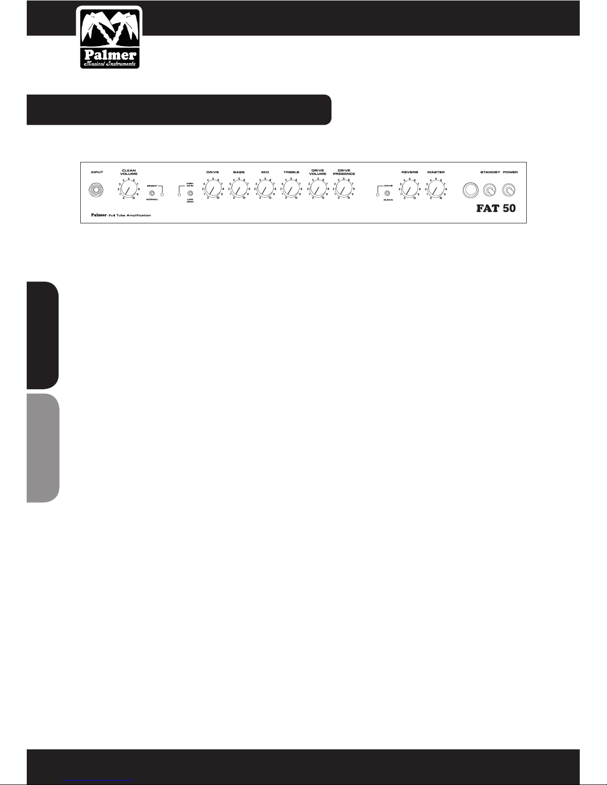
2 CoNNECToRS & CONTROLS:
FRONT PANEL FEATURES
1 INPUT
Connect your guitar to this socket using a high quality instrument cable (for all guitar output levels).
2 CLEAN VOLUME
This controls the level of the CLEAN channel. High settings produce a mild overdrive for blues and crunch tones
when you are using high output pickups.
3 BRIGHT/ NORMAL
This switch adds top end sparkle to both channels (“bright“ position, the green LED is lit).
4 GAIN
Switching to “High Gain“ mode dramatically increases channel sensitivity turning CLEAN into the crunch channel,
and DRIVE into Heavy Lead for aggressive hard rock sounds and the ultimate solo tone.
This function is also footswitchable. Connecting the dedicated Palmer 4-on-the-oor switch to the “Gain Select“
socket on the rear panel defeats the front panel switch. The yellow LED lights when the High Gain mode is selected.
5 DRIVE
This controls the sensitivity of the DRIVE channel and the amount of overdrive.
Tone Stack (passive EQ)
The Mid and Treble controls are highly interactive, e.g. increasing the amount of treble decreases midrange content, and vice versa. This feature is common to most tube amps enabling extensive tone shaping for a wide range
of sounds.
6 BASS
This controls the amount of low frequencies in your sound.
Caution: When set to 0 (hard left) the bass control mutes the amp.
7 MID
This controls the amount of midrange in your sound.
8 TREBLE
This controls the amount of high frequencies in your sound.
1 2 3 4 5 6 7 8 9 10 11 12 13
14 15 16

11
ENGLISHDEUTSCH
2 CoNNECToRS & CONTROLS:
9 DRIVE VOLUME
This controls the volume of the DRIVE channel (use to balance or match with the CLEAN volume).
10 DRIVE PRESENCE
This controls the upper midrange/high frequency response of the power amp when the DRIVE channel is selected.
11 DRIVE/CLEAN
This switches between the DRIVE and CLEAN channels. The red LED lights when the DRIVE channel is selected.
This function is also footswitchable. Connecting the dedicated Palmer 4-on-the-oor switch to the “Channel
Select“ socket on the rear panel defeats the front panel switch.
12 REVERB
This controls the amount of reverb mixed in with the direct signal. The integrated spring reverb can be switched
ON and OFF with the dedicated Palmer 4-on-the-oor switch.
13 MASTER
This controls the overall output level of the amp.
14 PILOT LAMP
This lights when the amp is switched on (and the correct mains power is present).
15 POWER
This is the ON/OFF switch for powering the amplier.
16 STANDBY
Turn on this switch 3 – 4 minutes after turning on the power switch. The standby function enables the tubes to
attain proper operating temperature and prolongs tube life. Also, use this switch to mute the amp between sets
while keeping the tubes at operating temperature.
12
ENGLISHDEUTSCH
2 CoNNECToRS & CONTROLS:
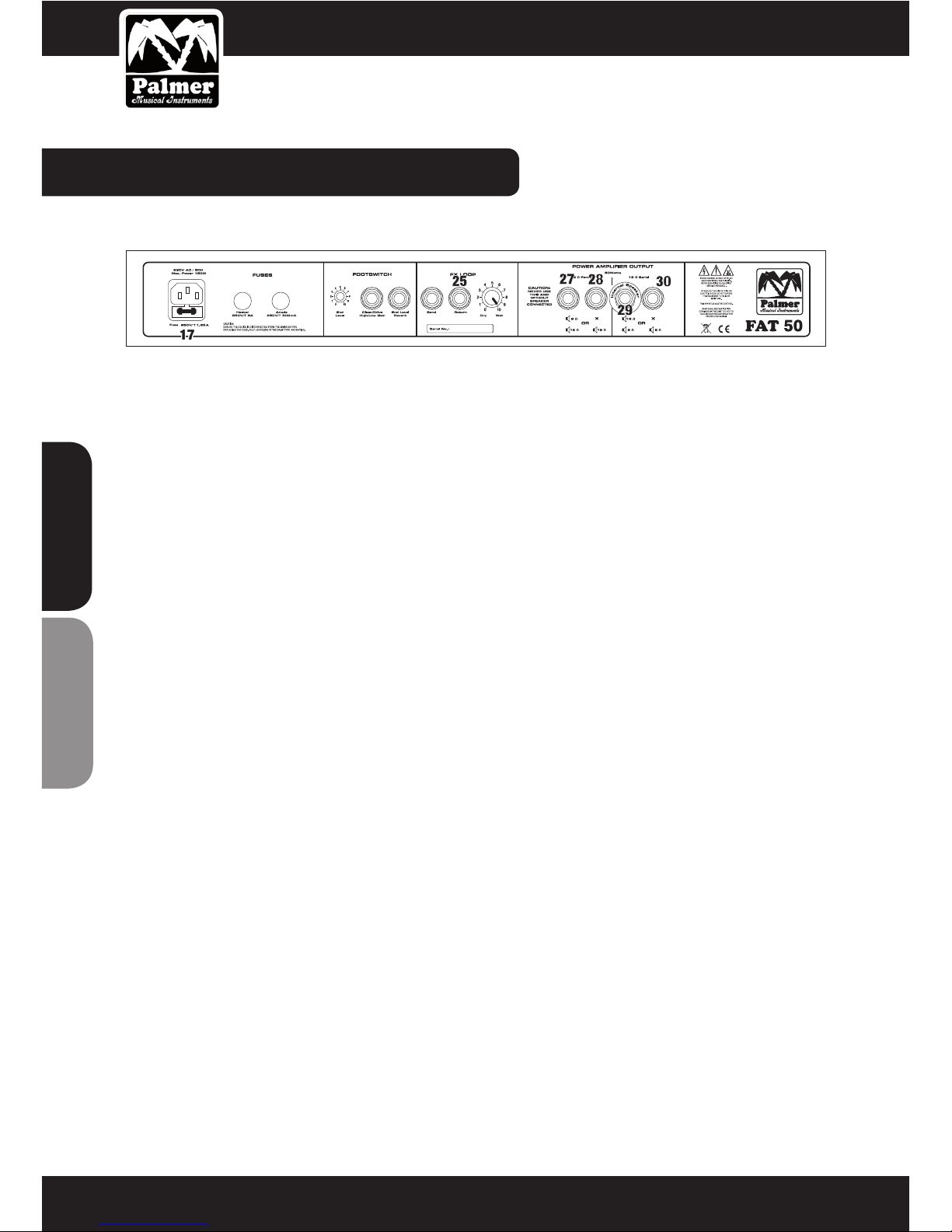
REAR PANEL FEATURES
17 MAINS IN
This is the socket for the included IEC power cord.
Caution: Do not operate the amp without the protective grounding connector!
Make sure the available mains input voltage matches the specifications on the rear panel of the amp before
powering up!
18 MAINS FUSE
The mains fuse is held in the IEC socket. Replace with the same type and value fuse only (see technical specifications).
19 HEATER FUSE
This holds the heater fuse for the preamp and power tubes. Replace with the same type and value fuse only (see
technical specifications). Tubes should be checked for defects if the heater fuse keeps blowing after replacement.
20 ANODE FUSE
This holds the anode fuse for the power tubes. Replace with the same type and value fuse only (see technical
specifications). The power tubes should be checked for defects if the anode fuse keeps blowing after replacement.
21 2ND LEVEL
This controls the alternate master level which is footswitchable with the dedicated 4-on-the-oor switch.
FOOTSWITCH
Connect the TRS leads from the Palmer 4-on-the-oor switch to remotely select channels, gain mode, master or
2nd level, and to turn the reverb on and off.
22 CHANNEL/ GAIN SELECT
23 2ND LEVEL/ REVERB ON/OFF
FX-LOOP (TUBE DRIVEN) This is where you connect external effects.
24 FX-SEND
This is the direct signal output. Connect this to the input of your effect(s).
F
U
S
E
F
U
S
E
F
U
S
E
F
U
S
E
F
U
S
E
F
U
S
E
F
U
S
E
z
18
19 20
21 22 23
24
26

13
ENGLISHDEUTSCH
2 CoNNECToRS & CONTROLS:
25 FX-RETURN
This receives the signal from your effect(s). Connect the output of your effect(s) to this socket.
26 DRY/WET
This selects parallel or series operation of the FX loop and controls the effect level.
POWER AMPLIFIER OUTPUTS
For correct impedance matching the FAT50 provides 8 and 16 Ohm loudspeaker outputs. The minimum load is 8
Ohms (1 x 8 or 2 x 16 Ohms). The internal loudspeaker of the combo version is connected to the 16 Ohm output
(labeled INTERNAL SPEAKER).
Caution: Do not operate the amp without appropriate loads (8 Ohms minimum) to prevent power amp damage.
Make sure the loudspeaker impedance matches the output impedance of the amp. Do not use loudspeakers rated
below the output power of the amp!
27/ 28 8 OHMS PARALLEL
The 8 Ohm loudspeaker outputs are paralleled. Use these to connect a single 8 Ohm cabinet, or two 16 Ohm
cabinets.
29/ 30 16 OHMS SERIES
The 16 Ohm loudspeaker outputs are wired in series. Use these to connect a single 16 Ohm cabinet (to the socket
labeled INTERNAL SPEAKER) or two 8 Ohm cabinets. The 16 Ohm loudspeaker of the FAT50 Combo must be
connected to the INTERNAL SPEAKER output (29).
Use the INTERNAL SPEAKER output (29) exclusively if you are connecting a single 16 Ohm cabinet. For two 8 Ohm
cabinets use the INTERNAL SPEAKER (29) and unlabeled 16 Ohm (30) outputs. An 8 Ohm cabinet must be connec-
ted to (29) to use output (30).
14
ENGLISHDEUTSCH
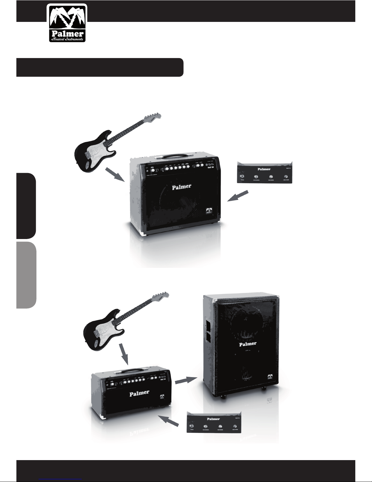
3 WIRING UP & SETTINGS:
COMBO
Ill. Amp/ Guitar/ Footswitch/ FX
HEAD:
Ill. Amp/ Guitar/ Footswitch/ FX/ Loudspeaker Cabinets

15
ENGLISHDEUTSCH
4 OPERATING THE FAT50:
CHANNEL SELECTION
Use the front panel CLEAN/ DRIVE switch or the Palmer 4-on-the-oor switch for channel selection. Red LEDs on
the front panel and the footswitch light up when the DRIVE channel is active.
THE GAIN FUNCTION
Use the front panel LOW GAIN/ HIGH GAIN switch or the Palmer 4-on-the-oor switch to select the gain mode. The
yellow LED on the front panel and a yellow LED on the footswitch light up when HIGH GAIN is active.
CLEAN channel + HIGH GAIN = CRUNCH mode
DRIVE channel + HIGH GAIN = HEAVY LEAD mode
THE BRIGHT/ NORMAL FUNCTION
Adding brilliance, the BRIGHT setting is indicated by the green LED on the front panel.
REVERB
Use the front panel reverb control to set the amount of reverb mixed in with your guitar signal. The integrated
spring reverb is always on unless the 4-on-the-oor switch is connected to turn it off and on. The (red) LED on the
footswitch lights up when the reverb is active.
MASTER AND 2ND LEVEL
Use the 4-on-the-oor switch to select MASTER volume or 2nd LEVEL (alternate master, rear panel). The red LED
on the footswitch lights up when MASTER is active.
THE FAT50 WITH EFFECTS
The FAT50‘s FX loop provides parallel or series operation and FX level setting. The rear panel control both switches
from parallel (DRY, hard left) to series (WET, fully clockwise) and mixes the FX signal in with the direct signal in
parallel mode (0 – 9). In series operation the power amp receives the FX signal only.
Caution: The FX control must be set to DRY when no effects are connected.
CONNECTING FX:
• Connect FX Send to the input of the effect, and the effect output to FX Return.
• Adjust the output level of the effect: turn the FX control fully clockwise (WET), set level short of clipping the FX
Return.
• Use the rear panel FX control to set the amount of effect mixed in with the direct signal.
The RETURN socket can also be used to connect another instrument, drum machine, MP3 player, etc. Use the FX
control to balance the guitar and additional signal levels.
 Loading...