

Page 1

Pall WS08 Series Water Sensor
instruction booklet
SIWS08EN
WS08
AB
Page 2

Pall does not accept warranty and liability claims either upon this publication
or in case of improper treatment of the described products.
The document may contain technical inaccuracies and typographical errors.
The content will be revised on a regular basis. These changes will be implemented
in later versions. The described products can be improved and changed at any
time without prior notice.
USA
FCC notice:
This equipment has been tested and found to comply with the limits for a Class B
digital device, pursuant to part 15 of the FCC Rules. These limits are designed to
provide reasonable protection against harmful interference in a residential installation.
This equipment generates, uses and can radiate radio frequency energy and, if not
installed and used in accordance with the installation manual, may cause harmful
interference to radio communications. However, there is no guarantee that
interference will not occur in a particular installation. If this equipment does cause
harmful interference to radio or television reception, which can be determined by
turning the equipment off and on, the user is encouraged to try to correct the
interference by one or more of the following measures:
- Reorient or relocate the receiving antenna.
- Increase the separation between the equipment and receiver.
- Connect the equipment into an outlet on a circuit different from that to
which the receiver is connected.
- Consult the dealer or an experienced radio/TV technician for help.
Caution:
Any changes or modifications not expressly approved by the party responsible for
compliance could void the user's authority to operate this device.
CANADIAN
ICES-003 notification:
This Device B digital apparatus complies with Canadian ICES-003.
Cet appareil numérique de la classe B est conforme à la norme
NMB-003 du Canada.
2
instruction booklet
Pall WS08 Series
Water Sensor
Because of developments in technology these data or procedures may
be subject to change. Consequently we advise users to review their
continuing validity annually. Part numbers appearing in this manual are
protected by the Copyright of Pall Europe Limited.
and Pall are trademarks of Pall Corporation.
Filtration. Separation. Solution is a service mark of Pall Corporation.
© 2008, Pall Europe Limited.
AB
Page 3

1. GENERAL 4
1.1 Symbol assertion 4
1.2 Safety instructions 4
1.3 Environmental information 4
2. PRODUCT DESCRIPTION 5
3. INSTALLA
TION 5
3.1 Installation of the housing 5
3.2 Installation of
the probe 5
3.2.1 General Safety instructions for installation 5
3.2.2 Installation of the probe directly in the process 6
3.2.3 Installation of the probe by utilizing the ball valve set 6
4. ELECTRICAL CONNECTIONS 8
4.1 Connection diagram 8
4.2 Connection diagram
alarm module / option 8
4.3 Connection configuration with plug connections / Option 8
5. OPERATING COMPONENTS 9
5.1 Circuit board 9
5.2 Display module
/ option 10
6. ALARM MODULE / OPTION 11
7. MAINTENANCE 12
7.1
Sensor replacement 12
7.2 Sensor pr
obe replacement / optional 12
7.3 Self-diagnostics and error messages 13
7.4 Replacement of sealing element 13
8. NETWORK 14
9. REPLACEMENT P
ARTS / ACCESSORIES 15
10. TECHNICAL DATA 16
1. GENERAL INFORMATION 17
2. INSTALLATION 17
3. ICONS ON THE TOOLBAR 18
3.1 File 18
3.2 Interfaces 18
3.3
Group 19
3.4 Transmitter 19
3.5 Information 20
4. ICON LIST 20
5. TA
BS 21
5.1 Analogue 21
5.2 Relay 21
5.3
Sensor / probe replacement 22
5.4 Information 23
6. OVERVIEW 24
6.1 How to set-up a new transmitter? 24
6.2 How to
read the configuration of a transmitter? 24
6.3 How to save the configuration in a transmitter? 24
DECLARATION OF CONFORMITY 25
Contents
HARDWARE
CONFIGURATION
SOFTWARE
3
instruction booklet
Pall WS08 Series
Water Sensor
AB
Page 4
1. GENERAL
The manual is a part of the scope of supply and serves to ensure proper handling and
optimum functioning of the instrument. For this reason, the manual must be read before
start-up.
In addition, the manual is for all personnel who require knowledge concerning transport,
setup, operation, maintenance and repair.
The manual must not be used for the purpose of competition without a written consent
from Pall and must also not be forwarded to third parties.
Copies for personal use are permitted.
All information, technical data and illustrations contained in these instructions are based
on information available at the time of publication.
1.1 Symbol assertion
This symbol indicates a safety instruction.
These safety instructions should always be followed carefully.
By not following these instructions injuries of persons or material damage
could happen.
Pall does not accept liability in the event of these
safety instructions being ignored.
This symbol indicates a note.
These notes should be observed to achieve optimum functioning
of the equipment.
1.2 Safety instructions
General Safety Instructions
• Excessive mechanical loads and incorrect usage should always
be avoided.
• In general, work on live components should be avoided and
when absolutely necessary should be performed by qualified
personnel only.
• Installation, electrical connection, maintenance and commissioning
should be performed by qualified personnel only.
Safety instructions for use of the alarm module
with voltages >50V
• To insulate the optional relay connections from the low-voltage side of
the water sensor, the partition provided for this purpose must be fitted
in the lower section.
• During operation of the instrument the modular housing must be
completely closed.
• The protection class of an opened housing corresponds to IP00 and
direct contact with components carrying dangerous voltages is therefore
possible. In general, work on live components should be avoided and
when absolutely necessary, should be performed by qualified personnel
only.
1.3 Disposal of Equipment
At the end of its life, the Water Sensor should be dismantled and disposed
of in accordance with all applicable local waste disposal laws and bylaws.
Where facilities exist, component parts of the unit may be recycled.
Details of the materials of construction are given on the product installation
drawing and if required, more detailed information regarding specific
items may be obtained from Pall or an approved agent.
If component parts of the equipment were previously contaminated with
the service fluid, an appropriate Manufacturer’s Safety Data Sheet (MSDS)
for the fluid should be obtained and read to ensure that contaminated
component parts are disposed of safely. Pall Europe Ltd., will meet it’s
obligations under the EU Directive on Waste Electrical and Electronic
Equipment (WEEE).
Hardware
4
instruction booklet
Pall WS08 Series
Water Sensor
AB
Page 5
Any product marked with the WEEE logo should be separated from other waste
streams to ensure that it can be recycled in an environmentally sound manner.
Pall Europe Ltd., accepts liability for New WEEE at the end of life and will dispose of
safely or recycle goods wherever possible. As defined in the Terms and Conditions
of Sale, Pall Europe does not accept any liability whatsoever for the remote collection,
shipping costs or packaging of returned goods. All costs associated with the return
of WEEE will be born by the customer.
Customers are responsible for the costs of shipping goods to the Central Collection
Point and Pall Europe Ltd accepts no liability whatsoever for any such costs.
Instructions to both customers and recyclers/treatment facilities regarding WEEE can
be found at www.Pall.com/weee.
2. PRODUCT DESCRIPTION
Pall Water Sensor series WS08 are specially designed for the measurement of water
content in oil.
The measured and the calculated values are available on two freely scaleable and
configurable analogue outputs. In addition, the relay output can be used for alarms and
process control (no relay available with RS485 options).
The modular housing enables a user-friendly operation and a quick
replacement of the sensor unit for service purposes.
3. INSTALLATION
3.1 Installation of the housing
The necessary dimensions for the mounting holes can be found
in the drawing to the left.
3.2.1
General safety instructions for installation
The Water Sensor probe is designed for use with pressures up to 20 bar
(290 psi). Precautions therefor
e need to be taken when installing or
removing the probe to ensure that it is not ejected from the system at
high velocities. The design of the probe is such that only when the gland
is fully unscrewed can the probe be removed form the system.
Hardware
5
instruction booklet
Pall WS08 Series
Water Sensor
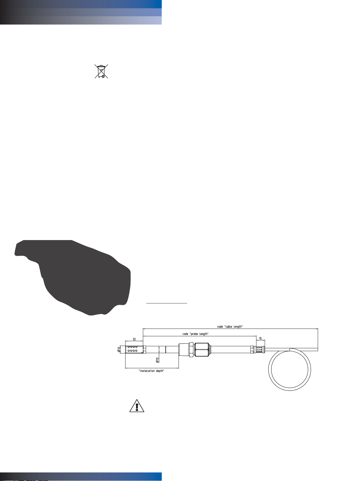
3.2 Installation of the probe
The probe should be located somewhere in the system where fluid will steadily
flow past the probe tip. A return line, or the wall of a reservoir are usually suitable.
Avoid locations where the fluid is frequently stagnant; also avoid places where
water or dirt/sludge could collect around the probe.
Installation depth: 100 mm probe 23 - 65 mm
200 mm probe 23 - 165 mm
AB
Page 6
Pall WS08 Series
Water Sensor
instruction booklet
6
Hardware
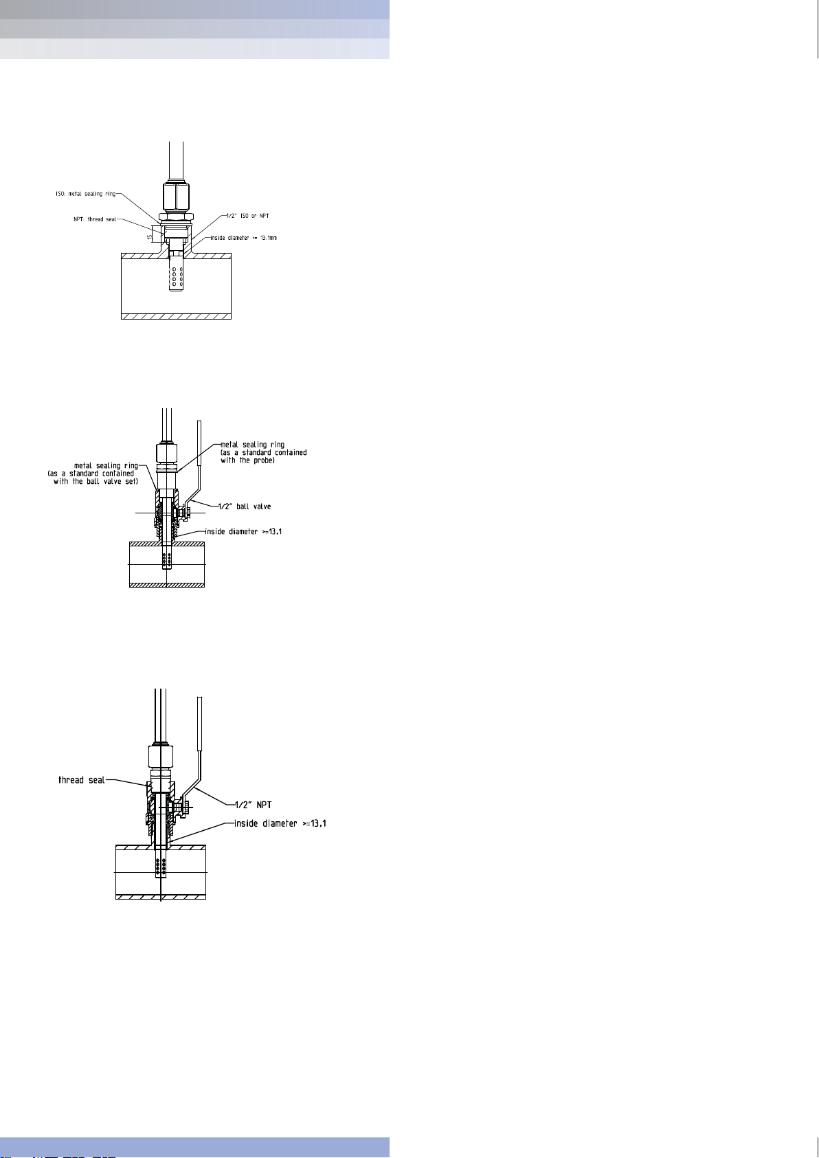
3.2.2 Installing a bushing/stub
The standard probe without ball valve requires either a ½” BSPP/ISO
or a ½“ NPT female bushing to be welded to the pipe or reservoir
where the probe is to be located. The NPT bush is required for the –
BO8 option probe. The long probe, when supplied with a ball valve,
requires a male threaded stub at the installation location. The
BSPP/ISO stub must be suitable for use with a bonded seal or metal
sealing washer.
Unless a suitable threaded port is already available, a ½” bush/stub
will need to be welded to the pipe or reservoir, the fluid having been
drained. Suitable cleaning/flushing procedures will be necessary once
the bushing/stub is fitted.
3.2.3 Installing the probe, without ball valve
Unscrew the gland-nut completely and check that the o-ring on the
cone of the gland is in good condition. If it is cut or damaged, replace
the o-ring.
Apply thread tape (-B08 option) to the thread of the nipple, or fit a
suitable seal ( C08 option, bonded seal or metal sealing washer). Fit
the nipple into the bush. Tighten sufficiently to ensure a fluid seal.
Slide the probe through the gland to locate the probe tip in the fluid
flow, and tighten the gland lock-nut onto the nipple to a torque of
30Nm (22 lbf ft). If a torque spanner is not available, firmly handtighten the nut, then spanner-tighten a further 50° (approximately 1
flat). Check that the probe is not free to slide in the gland – tighten
further if it can be moved by hand. Fill the system, pressurise to
normal working pressure, and check for leaks. For safety reasons,
keep away from the probe while the system is being pressurised, until
it is established that the probe will not be forced through the gland by
the pressure.
3.2.4 Installing the probe, with ball valve.
a) With the valve open, fit a suitable seal, or apply thread tape if
appropriate, and screw the valve onto the stub so that the handle
of the valve points away from the stub. Tighten sufficiently to seal
the joint. Close the valve, and fill/pressurise the system.
b) Unscrew the gland-nut completely and check that the o-ring on
the cone of the gland is in good condition. If it is cut or damaged,
replace the o-ring. Fit a suitable seal, or apply thread tape if
appropriate, and fit the nipple into the bush. Tighten the nipple
sufficiently to achieve a fluid seal. Screw the gland-nut onto the
nipple, sliding the probe back until the stop-ring contacts
the gland.
C08 option with ball valve
B08 option with ball valve
AB
Page 7
Pall WS08 Series
Water Sensor
instruction booklet
7
Hardware
c) Hand-tighten the gland nut until the probe is just free to slide/turn
within the gland, and slowly open the ball valve – there may be a
very slight leak of fluid around the gland-nut. Firmly and steadily
press the probe through the gland until the tip is in the flow of fluid.
Keeping the probe in position, tighten the gland-nut to 30Nm
(22 lbf ft). If a torque spanner is not available, firmly hand-tighten
the nut, then spanner-tighten a further 50° (approximately 1 flat).
Check that the probe is not free to slide in the gland – tighten
further if it can be moved by hand. Tightening the gland-nut should
eliminate the small leak which may occur during installation. For
safety reasons, keep away from the probe while the system is
being pressurised, until it is established that the probe will not be
forced through the gland by the pressure.
Note that a force of at least 1 kgf per bar of pressure (1.7 lbf per 10 psi)
is necessary to press the probe through the gland with the system
under pressure. Although the probe is designed for operation at up to
20 bar (290 psi) system pressure, it will be difficult to push the probe
through the gland and valve at pressures above about 4 bar (58 psi),
and there will be risk of damage to the probe. Ideally the system
should be depressurised to install the probe; the valve allows
installation/removal of the probe without draining the system.
3.3 Removal of the probe.
3.3.1 Removal of the probe, without ball valve.
a) Either completely isolate and depressurise the system where the
probe is located, or depressurise the whole system and drain it
until the fluid level is below the probe location.
b) Carefully loosen the gland nut, and having checked that there is no
residual pressure in the system, unscrew the gland-nut completely
and withdraw the probe.
3.3.2 Removal of the probe, with ball valve.
a) Depressurise the system. This is essential if the operating pressure
is above about 4 bar (58 psi), and recommended for lower pressures.
b) Carefully loosen the gland-nut – if the system is still pressurised,
apply a force along the probe to ensure that it is not forcibly pushed
back through the gland. Once the probe is free to move, withdraw it
through the gland until the stop-ring on the probe makes contact
with the gland. Close the valve. Do not force the valve closed if
there is a resistance, but investigate why the probe has not been
fully withdrawn.
c) Fully unscrew the gland-nut and withdraw the probe from the
valve assembly.
For reinstallation follow the instructions 3.2.2 or 3.2.3, omitting the
installation of the nipple, which should already be in place.
AB
Page 8
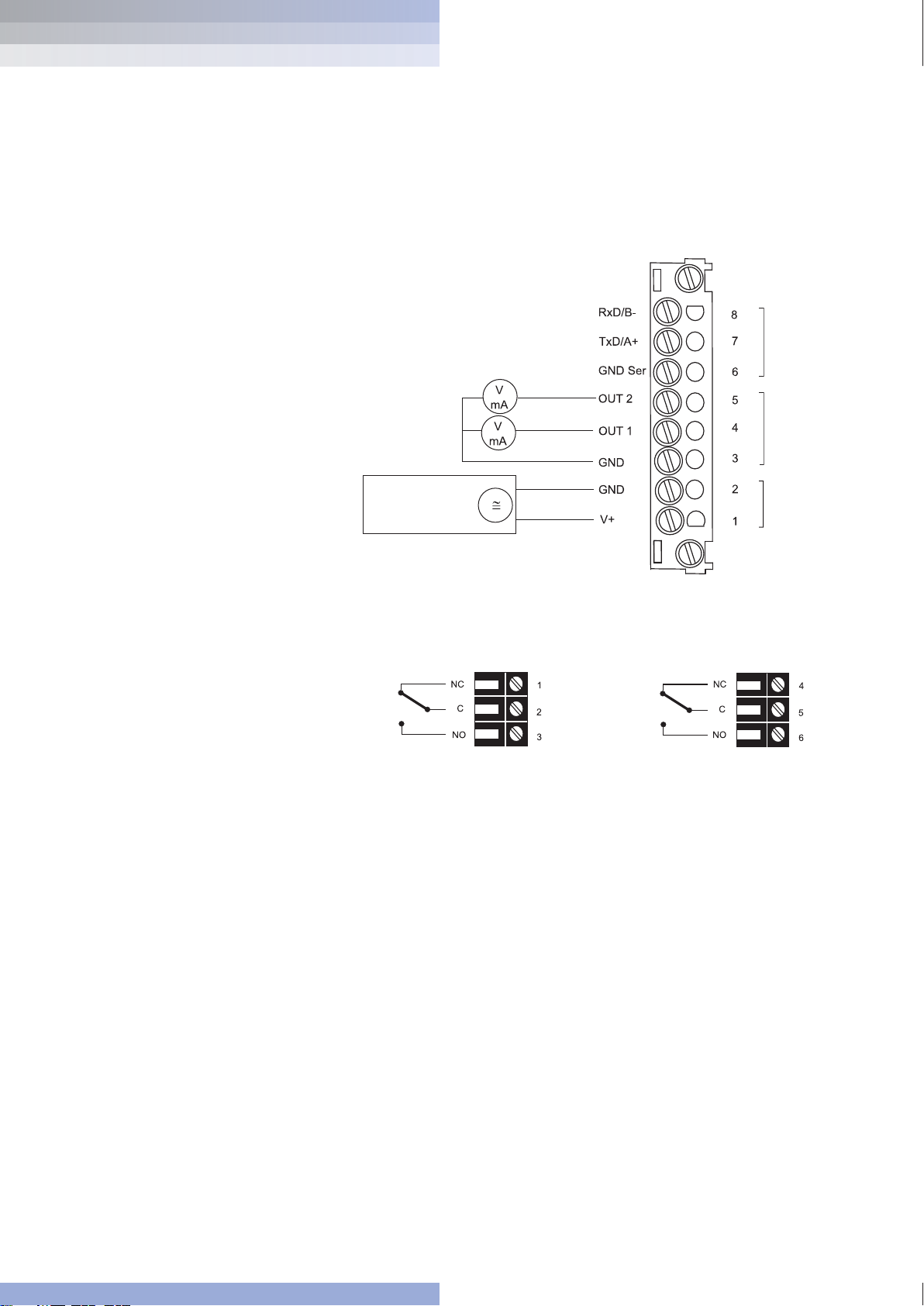
serial
data
output
analogue
output
supply
4.2 Relay connection diagram / Option
Rel 1
Rel 2
4. ELECTRICAL CONNECTIONS
Hardware
4.1 Connection diagram
instruction booklet
Pall WS08 Series
Water Sensor
8
AB
8 - 35 VDC
12 - 30 VAC
Page 9

4.3 Connection configuration with plug connections
4.4 Connection configuration of bottom part of the housing
with integrated power supply / 100...240V AC (option V01)
Description: Connection assignment:
GND-Ser 5
GND 4
Rxd/B- 3
V+ 2
Txd/A+ 1
The cable should be connected according to the number stamped in the
plug as shown in the above drawings.
Plug for RS485
connection
(front view)
Description: Connection assignment:
GND-Ser 5
GND 4
Rxd/B- 3
V+ 2
Txd/A+ 1
Plug for RS232
analogue output
(front view)
Description: Connection assignment:
GND-Ser 5
GND 4
Rxd/B- 3
Plug for 100-240V
metal housing
(front view)
Description: Connection assignment:
GND-Ser 5
GND 4
Plug for 100-240V
polycarbonate
housing
(front view)
External diameter of supply cable: 10-12mm (0.39-0.47”)
Maximum wire cross section: 1.5mm2 (AWG 16)
The protection of the supply cable against excess current and short-circuit
shall be in accordance with national and local codes.
Bottom and centerpeice of the housing shall be grounded!
Hardware
9
instruction booklet
Pall WS08 Series
Water Sensor
AB
Page 10

Pall WS08 Series
Water Sensor
instruction booklet
10
Hardware
1. Current / voltage output:
The default factory output setting is for current. The device can be
switched from current to voltage output using the configuration software
the two jumpers must be located as follows:
for current signals:
for voltage signals:
2. RS232 / RS485:
For the transition from RS232 to RS485 (network operation) these
jumpers must be removed.
3. Location of the network chip:
For refitting to RS485, an IC must be used (available as an option).
The notch on the chip must match the receiver slot!
4. Socket for optional display:
Pin connector for optional display.
5. Push-Buttons for calibration purposes:
See Hardware, chapter 7 “Maintenance
”
6. Diagnosis LEDs:
See Hardware, chapter 7 “Maintenance
”
5.1 Circuit board
After removal of the housing cover, the following operating
components on the circuit board may be accessed for adaptation
of the transmitter to the desired configuration. Each component is
discussed in more detail below.
5. OPERATING COMPONENTS
OUT2
OUT1
OUT2
OUT1
1. Current / voltage output jumpers
2. RS232 / RS485 jumpers
3. Location of the
network / RS485 chip
4. Socket for optional display
5. Push-button
6. Diagnosis LEDs
AB
I
I
U
U
Page 11

Pall WS08 Series
Water Sensor
instruction booklet
11
Hardware
SI SI US
T Temperature °C °F
%S % saturation % %
x Water content ppm ppm
1. MEASURED
VARIABLE:
2. UNITS: 3. MEASURED VARIABLE
SELECTION
5.2 Display module / Option
Press the ▲ or ▼ button
to select the desired
Measured Valve
1. Measured variable
2. Units
3. Measured variable selection and
4. Min / Max function
5. Measured values
6. Status line
4. MIN / MAX FUNCTION:
The WS08 Water Sensor can display the highest and lowest
measured value recorded since the last reset.
Highest measured value:
1. Select the desired measured variable.
2. To display the maximum value of the selected measured variable,
press the
▲
button for at least five seconds.
3.1. To reset the instrument to its normal operating status, press the
▲
button once again for five seconds.
3.2. If both buttons are pressed for at least five seconds while the
maximum value is displayed ➔ the “MAX” symbol disappears ➔
the maximum value will be deleted (Reset).
Lowest measured value:
1. Select the desired measured variable.
2. To display the minimum value of the selected quantity, press
the
▼
button for at least five seconds.
3.1. To reset the instrument to its normal operating status, press
the
▼
button once again for five seconds.
3.2. If both buttons are pressed for at least five seconds while the
minimum value is displayed ➔ the “MIN” symbol disappears ➔
the minimum value will be deleted (Reset).
AB
REL1
%S
aw: 0.38
38.2%
%S: 38.2%
%S: 38.2%
Page 12

Legend Minimum Maximum Unit
% saturation %S 0 100 %
Temperature T -40 (-40) 180 (356) °C (°F)
Water content x 0 99999 ppm
Note that the water content in ppm will not be displayed unless 4
constants, specific to the fluid, have been entered via the Configuration
software (see section 5.4 of the software description in this manual).
6. STATUS LINE:
- MIN; MAX: see point “MIN/MAX Function”
- CALIB LOW; CALIB HIGH: indicates the low or high humidity /
temperature calibration point.
- REL1 / REL2: Status Relay
- “ERROR 01....04”: see Hardware, chapter
7 “Self-diagnosis
and error messages
”
6. RELAY CONNECTION
The relay connection can be used for alarm and basic control functions.
Two relays are provided which can be configured using the configuration
software supplied (Note: Relays are not available with RS485 option).
The user thus has the option of setting the measured variable to be
monitored (%S, x, T) and the threshold hysteresis for each relay. (For
the procedure, see the Configuration Sofware, page 20 chapter 5.2
“Relay”)
max. switched voltage / max. switched current: 250 VAC / 6A
28 VDC / 6A
Minimum load: >100mA / 12V
The range over which the switching point of each relay can be adjusted
is given below:
5. DISPLAY RANGE:
The full range of each measured variable which can be displayed
is as follows:
Hardware
12
instruction booklet
Pall WS08 Series
Water Sensor
Legend Minimum Maximum Unit
% saturation %S 0 100 %
Temperature T -40 (-40) 180 (356) °C (°F)
Water content x 0 99999 ppm
AB
Page 13

%S: 38.2%
%S: 38.2%
Note, however, that the ppm output is not disabled if no ppm conversion constants
have been entered via the Configuration software (page 23, section 5.5).
If the Physical Quantity (see software, page 20, section 5.1) is set to ppm, but no
constants have been entered, the relay operation and appearance of REL legends
in the display will be unpredictable and meaningless.
Caution: The measured variable ppm (x) should only be used if
C1 to C4 constants have been loaded.
Switching relay 1:
Switching relay 2:
If relay 1 has tripped (ON),
then REL1 is displayed.
If relay 2 has tripped (ON),
then REL2 is displayed.
Hardware
13
instruction booklet
Pall WS08 Series
Water Sensor
ON
Relay status
Switching off
Switching on
Switching point
Hysteresis
OFF
ON
Relay status
Switching off
Switching on
Switching point
Hysteresis
OFF
AB
C
C
C
C
62
11
NC
1
12
2
3
NO
13
NC
11
1
12
2
NO
13
3
14
NC
4
15
5
6
NO
16
14
NC
4
15
5
NO
16
6
8°C
8°C
70
[ppm, %,°C/°F]
62
70
[ppm, %,°C/°F]
Page 14

• Sensor cleaning
Note: A reduction of the stabilisation time can be achieved by cleaning
the probe with n-Hexane resp. n-Heptane. Swirl the probe carefully in the
solvent then drip off and after that exhaust the air around the probe >0.5h.
Attention: Other solvents than above mentioned can corrode the
humidity sensor!!
• Fuse replacement (only with option V01)
7.1 Diagnostics
Self-diagnostics via the LEDs on the circuit board
(see section 5.1)
• Both LEDs off – no power to circuit board.
Check wiring and low voltage power supply
• Green LED flashing – circuit operating, microprocessor active.
• Green LED continuously on – electronic fault.
Contact Pall or your local supplier
• Red LED flashing – probe sensing element gaining moisture.
• Red LED continuously on – liquid water droplets on sensing element.
Allow the probe to dry out.
Note that during calibration operations using the buttons on the circuit
board, the significance of the LEDs being on, or flashing, is different from
the above. Humidity / Temperature Calibration using push buttons.
Self-diagnostics via messages on the display (when fitted)
• Error 1 – sensing element damaged. Contact Pall or your local supplier.
• Error 2 – liquid water on the sensing element. Allow the probe to dry out.
• Error 3 – temperature sensor open circuit or damaged. Contact Pall or
your local supplier.
• Error 4 – temperature sensor shorted. Contact Pall or your local supplier.
Definitions:
• Error
possible cause
➟ Measures / Help
• Display shows incorrect values
Error during re-adjustment of the transmitter
➟ Reset to factory calibration and repeat the calibration routine
Sensor defective
➟ Replace sensor
Output configured incorrectly
➟ PC - Software
• Transmitter failure
no supply voltage
➟ Check wiring and supply voltage
➟ only green LED is illuminated continuously
➟ Electronics defect
➟ contact the manufacturer
Hardware
7. MAINTENANCE
14
instruction booklet
Pall WS08 Series
Water Sensor
AB
Page 15

Hardware
15
instruction booklet
Pall WS08 Series
Water Sensor
8. NETWORK
Provided each of the WS08 Water Sensors has the RS485 communications option
fitted, up to 32 instruments can be connected to a single RS485 network. Full
details of networking WS08 Water Sensors, together with information on the
communications protocols, are given in a separate manual which will normally be
provided only when instruments fitted with RS485 communications are supplied.
The Pall manual corresponding to RS485 communications is titled:
“
Pall WS08 Series Water Sensor RS485 communications”
Network configuration:
Technical Data:
- Max. network size: 32 transmitters / COM-PORT of PC
- Max. network expansion: 1200m (3937ft) total length
- Transmission rate: 9600 Baud
Mounting notes:
Data cables: - minimum diameter of 4mm (0.16")
- 2-core twisted pair
- Typ. 50 pF/m, impedance 100 Ohm, non-shielded
- In accordance with the RS485 standard, cables
in category 5 (UTP), specified according to
EIA/TIA/ANSI 568, meet these requirements.
For high noise emissions, especially for large cable lengths, the use of shielded
cables is recommended. (Shield laid at GND)
1) Note: to enable optimum expansion, both ends of the network must be terminated with a
100 Ohm resistor.
2) Note: to adapt the RS232 interface on the PC to the RS485 network protocol, a signal converter
is required.
2 analogue
outputs
RS485
RS485
RS485
RS485
converter
RS232 (COM) interface
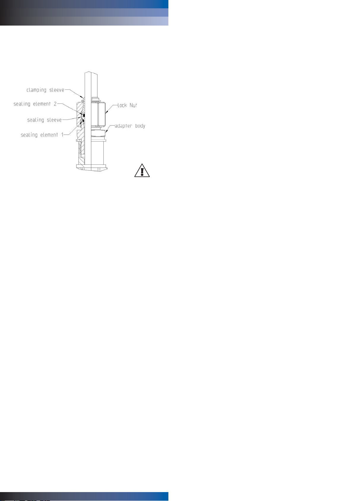
7.2 Replacement of sealing element1
In the event of sealing element wear or failure, replace with a
fluorocarbon sealing element 1 having 1.5 diameter and 13mm ID.
AB
1)
1)
2)
Page 16

9. REPLACEMENT PARTS / ACCESSORIES
Description Order Code
- LCD display and housing cover WS08D05-KIT
- RS232 interface cable, 3m WS08CA
- Ball valve set ISO (CO8 option) WSPV-KIT
- Sealing Element 1 HA050308
- Ball valve set NPT (BO8 option) WSPV-KIT-NPT
Plug connecors: For the network configuration, the following plug
connectors are also necessary:
- Y splitter: Siemens 6ES7 194-1KA01-0XA0
- Plug: Lumberg RSC 5/7
RS232/485 Converter: To adapt the RS232 interface on the PC to the RS485
network protocol, a signal converter.
Lumberg
RSC 5/7
Y splitter
Power supply +
Analog output
RS485
Network +
Power
supply
16
instruction booklet
Pall WS08 Series
Water Sensor
Hardware
AB
Page 17

17
instruction booklet
Pall WS08 Series
Water Sensor
10. TECHNICAL DATA
Saturation
Measuring range1 0...100%
Accuracy incl. hysteresis and nonlinearity in air ± 2% (0...90%RH) ± 3% (90...100%RH)
Response time at 20°C
(68°F) / t
90
typ. 10min in still oil
Temperature
Temperature sensor element Pt1000 (Tolerance class A, DIN EN 60751)
Working range sensing probe -40 ºC to 180 °C (-40°F to 356 °F)
Housing with display -20 ºC to 50 ºC (-4°F to 122 °F)
Housing without display -40 ºC to 60 ºC (-40ºF to 140 ºF)
Accuracy (typ.) +/- 0.5 ºC
Outputs
2
Two freely selectable and scaleable analogue outputs 0 - 5V Load Current < 1mA
0 - 10V Load Current < 1mA
4 - 20mA RL < 500 Ohm
0 - 20mA RL < 500 Ohm
General
Supply voltage Safety Extra Low Voltage 8 to 35 VDC
Safety Extra Low Voltage 12 to 30 VAC
Current consumption - 2x voltage output for 24V DC/AC: typ. 40mA
- 2x current output typ. 80mA
Pressure range sensing probe 0...20bar
System requirements for software WINDOWS 98 or later; serial interface
Serial interface for configuration
4
RS232C
Housing / Protection class polycarbonate / IP65; Nema 4
Cable gland M16 x 1.5 cable Ö 4.5 - 10mm
(0.18 - 0.39")
Electrical connection screw terminals up to max. 1.5mm
2
(AWG 16)
Electromagnetic compatibility according to EN61000-6-2 EN61000-6-3 ICES-003 ClassB
EN61326-1+A1+A2 FCC Part15 ClassB
Options
Display graphical LC display (128x32 pixels), with integrated pushbuttons
for selecting parameters and MIN/MAX function
Relay outputs 2 x 1 switch contact: 250V AC / 6A and 28V DC / 6A
threshold +
hysteresis can be adjusted with configuration software
1
refer to the working range of the humidity sensor! 4can be easily changed by software 4no data output
Hardware
AB
Page 18

CONFIGURATION SOFTWARE
LIMITATION OF LIABILITY
To the maximum extent permitted by applicable law, in no event shall Pall, its
employees or licensors or affiliates be liable for any lost profits, revenue, sales, data
or costs of procurement of substitute goods or services, property damage, personal
injury, interruption of business, loss of business information or for any special, direct,
indirect, incidental, economic, cover, punitive, special or consequential damages,
however caused and whether arising under contract, tort, negligence, or other theory
of liability arising out of the use of or inability to use the software, even if Pall or its
licensors or affiliates are advised of the possibility of such damages. Because some
countries/states/jurisdictions do not allow the exclusion or limitation of liability, but
may allow liability to be limited, in such cases, Pall, its employees’ or licensors’ or
affiliates' liability shall be limited to U.S. $50.
1. GENERAL INFORMATION
The configuration software was developed by Pall to allow fast and easy
configuration of individual transmitters.
This software tool is included in the scope of supply.
System requirements: MS WINDOWS 98
®
or higher; RS232 serial interface
2. INSTALLATION
Insert the CD-ROM supplied with the transmitter into the PC and open the set-up
application. Follow the instructions of the dialogue menus to set the desired language
and all other parameters for installation. At the end of the routine, the software is
installed and the Readme file or the program will be automatically opened.
Note:
Before any reinstallment or upgrade the older version must first be
uninstalled (the User will be notified during the installation routine and the process
will be interrupted automatically).
To remove the previous version, open the software folder in the system control panel.
All of the programs installed on your system are located here. Uninstall the WS08
Configurator by clicking on the appropriate button and then reinstall or upgrade.
Hardware
18
instruction booklet
Pall WS08 Series
Water Sensor
AB
Page 19

Configuration software
19
instruction booklet
Pall WS08 Series
Water Sensor
Note:
Within the Water Sensor Configurator software the word “transmitter”
is used to refer to the WS08 Water Sensor.
Users of this software should realize that “transmitter” and
“water sensor” can be used interchangeably.
3.1 File
Load: Loads a file with a saved transmitter configuration.
Save: Saves the current transmitter configuration in a file.
New Workspace: Opens a file for a new tree.
Open Workspace: Opens existing trees.
Save Workspace: Saves the current trees in an archive file.
Note:
The functions “Save Workspace” and “Open Workspace” apply to the
tree structure only, not to the configurations of individual transmitters!
3.2 Interfaces
Select: Selects the serial interface (COM port) for
communication with the transmitters.
Following functions are available:
use / do not use: Marked COM ports are greyed out and deactivated
for the configuration software (e.g. COM for
integrated Notebook Modem).
Note:
A disabled interface (shaded = do not use), can be enabled by clicking
on the “use” button.
3. ICONS ON THE TOOL BAR
AB
Page 20

3.3 Group
The icon “Group” provides the option of combining transmitters in
groups. A group may consist of transmitters used in the same
application, for instance assigned to a building.
New: Creates a group or adds another group into
an existing structure.
Delete: Deletes groups within a tree.
Rename: Changes the name of a transmitter group.
3.4 Transmitter
New transmitter:
A new transmitter is created in the tree.
This procedure requires the input of a number of parameters:
Group: Assigns a transmitter to a group.
Network: The check box network must be selected when
several WS08’s are operated in a network.
Network address: Input of the network address for the WS08
transmitter for unique assignment within the
network (see label on the transmitter housing).
For use only with RS485 equipped systems.
Interface: Selects the interface for connecting the transmitter
to the network. (For information on how to set up
a COM port, see Configuration Software, chapter
3.2 “Interfaces”).
Name: Assigns a meaningful name related to the
transmitter. This name is displayed in the tree
under the relevant group (e.g.: Clean Room).
Configuration software
20
instruction booklet
Pall WS08 Series
Water Sensor
AB
Page 21

21
instruction booklet
Pall WS08 Series
Water Sensor
Preferences: Displays the preferences for all transmitters that
have been set-up. The preferences may also be
changed here.
Delete transmitter: Deletes from the tree structure the selected
transmitters, or the selected groups.
Read: Reads and displays the configuration parameters
of the selected transmitter.
Read All: Reads the configuration for all transmitters.
Note:
Only those parameters that have the same value for all transmitters of
the network will be displayed. Other values are shaded and can not be
selected or changed.
Write: Writes the current configuration to
the selected transmitter.
Write All: Writes the current configuration to
all selected transmitters.
Set the configuration for a transmitter, then select the appropriate
network in the tree and write the configuration all transmitters of the
target group using the command “Write All”.
Warm Start: Resets and restarts the microprocessor of the
selected transmitter.
3.5 Information
Version: Displays the version number of the WS08
software currently installed and the contact
information for Pall.
4. ICON LIST
“Load File” (see Configuration Software, chapter 3.1 File)
“Save File” (see Configuration Software, chapter 3.1 File)
“New Transmitter” (see Configuration Software, chapter 3.4 Transmitter)
“Read Transmitter” (see Configuration Software, chapter 3.4 Transmitter)
“Save Transmitter” (see Configuration Software, chapter 3.4 Transmitter)
“Read All Transmitters” (see Configuration Software, chapter 3.4 Transmitter)
“Write All Transmitters” (see Configuration Software, chapter 3.4 Transmitter)
“Delete Transmitter” (see Configuration Software, chapter 3.4 Transmitter)
Configuration software
AB
Page 22

5.1 Analog
For the configuration of both analogue outputs.
Range: Using the drop-down input field, select either a
standardized output signal (0-5V, 0-10V, 0-20mA,
4-20mA) or a user-defined current/voltage output
range (upper and lower limits may be selected as
required between the limits indicated).
Physical Quantity: Selects the output physical quantities.
Highest /
Lowest Limit: Sets the desired scaling of the output. The limits
must fall within the operating range indicated above.
Units: Selects between SI or US units.
5.2 Relay
Used to set both alarm outputs.
Physical Quantity: Selects the physical quantity for each alarm output.
Switching
Point High: Sets the high switching point.
Hysteresis: Sets the switching hysteresis that should be
maintained each time the signal falls below the
upper switching limit.
Configuration software
5. TABS
22
instruction booklet
Pall WS08 Series
Water Sensor
Relay status
Switching off
Switching on
Switching point
Hysteresis
Note:
The word “TABS” refers to the selectable pages titled Analog, Relay,
Calibration and Information. These Tabs can be accessed by clicking on
the desired one.
AB
8°C
62
70
[ppm, %, °C/°F]
Page 23

Configuration software
23
instruction booklet
Pall WS08 Series
Water Sensor
5.3 Sensor / Probe Replacement
Note: For sensing elements and probe replacement, please contact
your local Pall representative.
Note: A reduction of the stabilisation time can be achieved by cleaning
the probe with n-Hexane resp. n-Heptane. Swirl the probe carefully in the
solvent then drip off and after that exhaust the air around the probe >0.5h.
Attention: Other solvents than above mentioned can corrode the
humidity sensor!!
1-point calibration Humidity:
Fast and easy calibration for accurate measurement results at a defined
working point (humidity point).
1) Stabilise the probe of the desired humidity for min. 30 minutes.
2) Click on the Humidity "1-point calibration" button. The measured
values will now appear in both input fields.
3) Replace the value in the input field "Humidity Reading" with the
reference humidity (value of the saline solution or display of HUMOR 20).
4) By clicking on "Save", the humidity reading for the transmitter will be
adjusted to the reference humidity.
5.4 Calibration
AB
Page 24

Pall WS08 Series
Water Sensor
instruction booklet
24
2-point calibration Humidity:
Calibration for accurate results over the entire measurement range.
1) Place the probe at the reference humidity (lower point).
2) Click on the Humidity 2-Point Calibration button.
(In a separate window, the measured values will appear in
both input fields)
3) Replace the value in the input field "Humidity Reading" with
the reference humidity. (Value of the saline solution or display
of HUMOR 20)
4) By clicking on "Save", the humidity reading of the transmitter will
be adjusted to the reference humidity. Now the 30-minute
stabilisation period starts.
5) Place the probe at the reference humidity (high point).
6) Before continuing wait till the 30-minute stabilisation period is over.
7) Replace the value in the input field "Humidity Reading" with the
reference humidity. (Value of the saline solution or display of HUMOR 20)
8) By clicking on "Save", the humidity reading of the transmitter will be
adjusted to the reference humidity.
9) The process is complete when the message "Two-point calibration
successful" appears.
1-point calibration Temperature:
If the working range is limited to a narrow temperature range, one-point
calibration will be sufficient within this working range.
1) Place the probe at the reference temperature and allow stabilisation
for approx. 30 minutes.
2) Click on the Temperature 1-Point Calibration button.
The measured value will appear in both input fields.
(see additional window)
3) Replace the value in the input field "Temperature Reading" with the
reference temperature.
4) By clicking on "Save", the temperature reading of the transmitter will
be adjusted to the reference temperature.
5) The process is complete when the message "Calibration Successful"
appears.
Factory Calibration:
Using the "Factory Calibration" button the user can reset all calibration
values back to their original factory setting. The "Factory Calibration"
button is located on the Calibration Tab (see photo at the start of section
5.4 Calibration).
Configuration software
AB
Page 25

Pall WS08 Series
Water Sensor
instruction booklet
25
5.6 Information
Here you will find information on the selected transmitter.
Serial number: Used to track the manufacturing data of
the transmitter.
Network address: Each transmitter is assigned a unique network
address at the factory for precise identification.
Type: Name of the transmitter series.
Humidity
Calibration Date: Provides information on the date of the last
humidity calibration, but only if the configuration
software was used.
Note: Calibrations performed directly on the circuit board are
not recorded!
Temperature
Calibration Date: Provides information on the date of the last
temperature calibration, but only if the
configuration software was used.
Note: Calibrations performed directly on the circuit board are
not recorded!
Firmware /
Version: Provides information on the software version
implemented in the transmitter (internal).
Configuration software
5.5 Parameter
Moisture content:
Enter the parameter C1, C2, C3 and C4 for calculation of the water
content x [ppm].
Note: The saturation content is PPM (parts per million) can be displayed if
the proper C1, C2, C3, & C4 constants have been loaded. It is important
to point out the constants vary for each oil manufacturer and oil type.
The user is cautioned not to experiment by entering arbitrary constants
since this will result in an inaccurate displayed PPM valve.
Contact your local Pall Corporation representative for more details.
Air pressure:
If a transmitter of the WS08 series is operated far above sea level or a
measurement is required at high process pressure, the prevailing ambient
pressure can be entered to increase the accuracy of the derived values /
computing funtions.
AB
Page 26

6.1 How to set-up a new transmitter/Water Sensor?
Note: Within the Water Sensor Configurator software the word
“transmitter” is used to refer to the WS08 Water Sensor.
Users of this software should realize that “transmitter” and
“water sensor” can be used interchangeably.
Menu “File” --> “New Workspace”
Assign a name to the file and select the location to save the file
Menu “Group” --> “New Group”
Assign and add a name, then click on “Finish”
Menu “Transmitter” --> “New Transmitter” or
Button “New Transmitter”
Select the group for the transmitter using the pull-down menu “Group”.
Specify the COM port (serial interface) of the PC / Notebook in the
pull-down menu “Interface”.
Enter the name for the transmitter in the “Name” field.
Complete the “New Transmitter” process by clicking on the
button “Add”.
6.2 How to read the configuration of a transmitter/Water Sensor?
The current configuration of the selected transmitter can be
read by clicking on the button “Read Transmitter” or by selecting
“Transmitter” --> “Read Transmitter”.
If the configuration is already loaded, the configuration data in the TABS can
be modified.
6.3 How to save the configuration in a transmitter/Water Sensor?
A modified configuration in the TABS can be saved to the selected
transmitter by clicking on the button “Save Transmitter” or by selecting
“Transmitter” --> “Save Transmitter”.
Configuration software
26
instruction booklet
Pall WS08 Series
Water Sensor
6. OVERVIEW
AB
Page 27

27
instruction booklet
Pall WS08 Series
Water Sensor
DECLARATION OF CONFORMITY
AB
Page 28

Pall WS08 Series
Water Sensor
instruction booklet
28
NOTES
AB
Page 29

Pall WS08 Series
Water Sensor
instruction booklet
29
NOTES
AB
Page 30

Because of developments in technology these data or procedures may be subject to change. Consequently
we advise users to review their continuing validity annually. Part numbers quoted above are protected by the
Copyright of Pall Europe Limited.
and Pall are trademarks of Pall Corporation.
Filtration. Separation. Solution is a service mark of Pall Corporation.
©2008, Pall Europe Limited.
June 2008. Printed in England. SIWS08EN
Pall Industrial Manufacturing
New York - USA
800 333 7255 toll free
+1 516 484 3600 telephone
+1 516 625 3625 fax
Portsmouth - UK
+44 (0)23 9230 3303 telephone
+44 (0)23 9230 2507 fax
Visit us on the web at www.pall.com
Pall Corporation has offices and plants throughout the world in locations including:
Argentina, Australia, Austria, Belgium, Brazil, Canada, China, France, Germany, India,
Indonesia, Ireland, Italy, Japan, Korea, Malaysia, Mexico, the Netherlands, New Zealand,
Norway, Poland, Puerto Rico, Russia, Singapore, South Africa, Spain, Sweden, Switzerland,
Taiwan, Thailand, United Arab Emirates, United Kingdom, United States, and Venezuela.
Distributors are located in all major industrial areas of the world.
AB
 Loading...