

Page 1

UR310
EN
ENCNEN
CN
EN
DE
CN
EN
ES
DE
CN
EN
ES
DE
FR
CN
EN
ES
DE
FR
CN
IT
EN
ES
DE
FR
JP
CN
IT
KR
EN
ES
DE
FR
JP
CN
IT
UR310 Series
EN
UR310 Service Instructions
CN (Simplified) UR310 使用说明书
CN
(Traditional)
DE UR310 Wartungsanleitung
ES Instrucciones de mantenimiento de UR310
FR
Instructions de serviceUR310
IT Istruzioni d’uso e manutenzione per UR310
JN UR310アフターサービス説明書
KR UR310 서비스 지침 지침
中文
UR310使用說明書
ENGLISH
中文
(SIMPLIFIED)
中文
(TRADITIONAL)
DEUTSCHESPAÑOL
FRANÇAIS
ITALIANO
日本語
한국어
service instructions
M&ESIUR310c
Page 2

UR310
UR310 Series
RETURN LINE FILTERS service instructions
1 Specifications
Housing materials:
Head and Cover: Ductile cast iron
Tube: Carbon steel
Maximum operating pressure:
41 bar (600 psi)
Proof pressure:
62 bar (900 psi)
Minimum burst pressure:
165 bar (2400 psi)
Element burst pressure:
UE310 element 10 bard (150 psid) differential minimum
Operating temperature range:
-29° C to 120° C (-20° F to 250° F) with fluorocarbon seals
for petroleum based and specified synthetic fluids
60° C (140° F) maximum in HWCF, water-oil emulsion
or water glycol
Bypass valve setting options:
1.7 ± 0.2 bard (25 ± 3 psid) cracking pressure
4.5 ± 0.5 bard (65 ± 7 psid) cracking pressure
Non bypass
CAUTION:
Maximum surge flow should not exceed 1.3 times
normal flow.
Seals:
Fluorocarbon
The actual operating conditions should be checked by the
user to ensure that the element, housing and all seals are
compatible with the fluid and application, and are within local
safety codes. Please contact Pall or an approved distributor if
further information is required.
2 Receipt of equipment
The filter housing, and any optional equipment, are packed
individually for assembly by the customer. Unpack carefully
and ensure optional items are not mislaid in packaging to be
discarded.
3 General sources of information
3.1 For dimensions, operating parameters, assembly/
element part number, ordering information, notes,
performance data and specifications refer to datasheet.
3.2 This equipment has been assessed in accordance with
the guidelines laid down in the European Pressure
Directive 97/23/EC and has been classified within sound
engineering practice S.E.P. We hereby declare the
equipment meets the requirements of article 3, section
3, thus meeting the directive requirements. Under the
provisions of this directive the filter assembly is suitable
for use with group 2 fluids only.
3.3 Where under reasonably foreseeable conditions,
including external fires, the allowable limits could be
exceeded, suitable protective devices must be installed
by the customer within the connecting fluid system.
4 Installation of housing
4.1 The filter can be installed in any attitude, but for ease of
servicing, it is recommended that it be installed vertically
with the filter tube and cover pointing upwards (UR310) or
with the filter tube and cover pointing downwards (UR310H).
4.2 The minimum clearance required for element removal is
as follows:
4.2.1 UR310 series (cover service): 248mm (9.8") for
length 8, 383mm (15.1") for length 13, 553mm
(21.8") for length 20 and 1061mm (41.8") for
length 40 housings.
4.2.2 UR310H series (head service): 140.97mm (5.55")
for all lengths.
4.2.3 The UR310 Housing is supplied without a filter
element. For element installation and servicing
procedures, refer to Section 7.
4.3 Threaded differential pressure devices, when fitted,
must be torque tightened to 40 lbft or 54 Nm. All visual
indicators must be clearly visible.
NOTE: The UR310 head is supplied with a machined differential
pressure warning device port, fitted with a plastic shipping plug.
If no differential pressure warning device is ordered, the shipping
plug must be removed and replaced with a ‘B’ type blanking plug
(P/N HA9000-A104Z) and torque tightened to 40 lbft or 54 Nm.
NOTE: Never place the port plug in this port without first
installing uniform size -014 O-ring in lower O-ring groove,
otherwise a small bypass flow will result, allowing contaminant
downstream of the filter element.
CAUTION:
Never operate the filter unless a warning device port
is sealed.
4.4 Mount the filter assembly in position using 1/2" - 20UNF
- 2B (A or D ports) or M12 x 1.75 - 6H (C or F ports)
bolts in the holes on the head mounting pads. Torque
bolts to 20 - 25 lbft or 27 - 34 Nm.
4.5 Use a check valve downstream of the filter if there is a
possibility of reverse flow.
4.6 Install the filter housing using additional piping/valving to
allow complete filter assembly bypass if filter maintenance
is required without system shutdown. This series is not
available in a duplex or service bypass configuration.
CAUTION:
Reverse flow through filter element will cause damage.
NOTE: Piping supports should be provided as close as is
practicable to the port connections in order to minimize
external loads. This filter assembly must not be electronically
isolated from the users earthing system. This filter assembly
must be earthed by connecting the users earthing system to
one of the inlet/outlet connections.
4.7 Connect lines or hoses to housing inlet and outlet ports.
WARNING:
USE FITTINGS OR ADAPTORS COMPATIBLE WITH
PORTS SUPPLIED AS SHOWN BY PART NUMBER
ON NAMEPLATE AND NOTED IN DATA SHEETS:
USE OF INCORRECT FITTINGS OR ADAPTORS CAN
CAUSE FILTER HOUSING OR MANIFOLD FAILURE
RESULTING IN LOSS OF PRESSURE AND POSSIBLE
SYSTEM FAILURE OR PERSONAL INJURY.
2
Page 3
UR310
Pin 3
UR310 Series
RETURN LINE FILTERS service instructions
NOTE: Painting of the filter housing is optional. The coating
on the filter housing is a suitable painting base. Cover the
differential pressure warning device and nameplate if painting
of the housing takes place.
4.8 Bleed the filter
4.8.1 UR310 (cover service): Bleed the filter by opening the
vent plug (7) at the top of filter one and one-half turns.
Jog system and fill filter until all air bleeds through the
plug, then torque tighten plug to 12 ft/lb or 16 Nm.
4.8.2 UR310H (head service): Bleed the filter by opening the
vent plug (7b) on the head one and one-half turns. Jog
system and fill filter until all air bleeds through the plug,
then torque tighten plug to 12 ft/lb or 16 Nm.
Pressurize system fully and check for leaks; if leaks occur
refer to section 5.
CAUTION:
Failure to bleed the filter housing adequately will
increase the dissolved air content of the system fluid
which will shorten fluid life and may cause other
problems in the system.
5 Routine maintenance
5.1 Pall filters do not normally require special attention
except for periodic monitoring of the differential pressure
warning device. Schedule replacement of filter element
every six months or sooner, and have ample supply of
spare elements available.
5.2 If external leakage is noted, replace O-ring at leak. If
leakage persists, check sealing surfaces for scratches or
cracks; replace any defective parts.
5.3 Differential pressure devices actuate when the element
needs changing or because of high fluid viscosity in
‘cold start’ conditions. If ‘cold start’ conditions exist, see
Section 6.2 and 6.3.
5.4 A dirty system can quickly plug a new filter element,
especially with Pall high efficiency filter media. It may
require one or two initial element changes to stabilize
element life. If element life is short or differential
pressure is excessive, filter may be undersized; refer to
the sizing and selection section of the product literature
or contact your local Pall representative.
5.5 Make sure element change labels are clean and
undamaged. Replace illegible labels with the appropriate
new labels.
6 Differential pressure devices
Reference should be made to product literature for dimensions,
operating parameters, part numbering, ordering information
and specifications.
6.1 Differential pressure devices actuate when the element
needs changing or because of high fluid viscosity in
‘cold start’ conditions.
6.2 If stainless steel visual indicator is fitted and actuates
during ‘cold start’ (red button extends 5mm, 3/16"), reset
by depressing the button when the normal operating
temperature is reached. If indicator actuates after
resetting, replace element. If brass visual indicator
is fitted and actuates during ‘cold start’ (flag inside
indicator changes to red), it will automatically reset when
normal operating temperature is reached. If indicator
is still actuated after normal operating temperature is
reached, replace element.
NOTE: Option ‘P’ visual indicator has thermal lockout and
manual reset. No signal below 0° C (32° F), signal above
29° C (80° F).
3
6.3 Use of both positive indication (green light) and negative
indication (red light for dirty element) is recommended to
effectively monitor filter element life.
6.4 If the electrical switch actuates (e.g. red light comes on)
during cold start, continue operating until the signal (red
light) goes out as system warms to normal operating
temperature. This feature can be used as ‘warm up’
indication in operating procedures. If the warning signal
(red light) remains or appears when system is warm,
replace the filter element.
Electrical connections and ratings are dependent on
indicator chosen. Typical values only are shown below:
110 VAC = 4A (inductive),
220 VAC = 4A (inductive),
28 VDC = 3A (inductive),
48 VDC = 1A (inductive),
125 VDC = 0.25A (inductive),
Maximum inrush - 24 amps.
Underwriter’s lab. Inc. listed ratings of pressure switch
(Microswitch) options are:
4 amps at 250 VAC
0.25 amp resistive at 220 VDC
0.50 amp resistive at 110 VDC
Electrical differential pressure switch operation:
When preset differential pressure is exceeded continuity
switches from Normally Closed (NC) - Common to Normally
Open (NO) - Common.
When differential pressure decreases below pre-set value,
continuity returns to Normally Open (NO) - Common to
Normally Closed (NC) - Common.
4A (resistive)
4A (resistive)
5A (resistive)
1.5A (resistive)
0.5A (resistive)
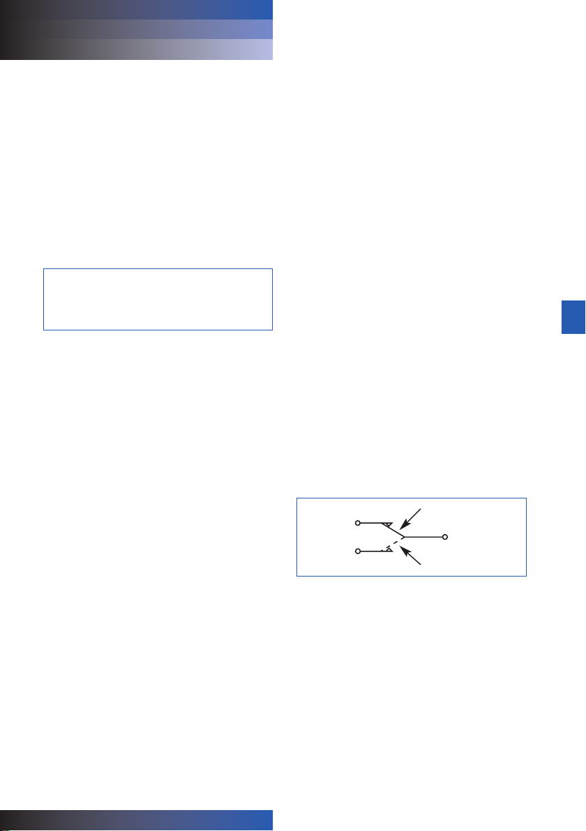
Figure 1 - Switch Circuit Diagram
NORMALLY
CLOSED
(NC) Pin 2
NORMALLY
OPEN (NO)
See individual indicator options for connection details.
LOW DIFFERENTIAL PRESSURE
COMMON
Pin 1
HIGH DIFFERENTIAL PRESSURE
ENGLISH
Page 4

UR310
UR310 Series
RETURN LINE FILTERS service instructions
7 Filter element servicing
During servicing, the external surfaces of the filter assembly
must be cleaned to remove any dust deposits.
Servicing must be conducted using suitable tools that do not
present a hazard.
Servicing must not be carried out when a potentially explosive
atmosphere is present.
CAUTION:
Filter elements should be replaced upon indication or
at specified intervals, six months maximum. Failure
to change the element will cause the filter to go
on bypass.
Refer to Service Parts List (Section 9) for item numbers for
applicable replacement element series. Remove and replace
element as follows:
7.1 Turn off and depressurize the system.
WARNING:
FAILURE TO DEPRESSURISE THE FILTER
BEFORE SERVICING ELEMENT COULD RESULT
IN EXPLOSIVE LOSS OF FLUID, DAMAGE TO
EQUIPMENT AND POSSIBLE PERSONAL INJURY.
7.2 For UR310 series (cover service):
Open vent plug (7) at the top of the filter one and
one-half turns.
Open drain plug (7b) on the filter head and drain fluid
into a suitable waste receptacle. Replace and torque
tighten drain plug to 12ft/lb or 16Nm. Unscrew and
remove cover (3) from tube (2) counter-clockwise when
viewed from above. It may be necessary to use a 1"
socket wrench on the hexagon on the cover (3) to
loosen the cover initially.
NOTE: The UR310 series assembly is equipped with Pall’s
‘Auto-Pull’ element extraction mechanism to facilitate element
removal. While removing the cap, tabs on the element endcap
lock into hooks in the cap and the element is automatically
pulled from the nipple.
7.3 For UR310H series (head service):
Open drain plug (7) at the bottom of the bowl assembly
(tube and cover) and drain fluid from the bowl into a
suitable waste receptacle. Replace and torque tighten
drain plug to 12 ft/lb or 16 Nm. Unscrew and remove the
bowl assembly (2 and 3) from head (1) counter-clockwise
when viewed from below. It may be necessary to use a 1"
socket wrench on the hexagon on the cover (3) to loosen
the cover initially.
7.4 Element replacement (UE310 Series): Remove filter
element (8), if already fitted, and carefully inspect the
interior surface (flow through the element is in-to-out) for
visible contamination. Normally no dirt should show, but
visible dirt or particles can be an early warning of
system component failure. Discard both the filter
element and its O-ring. The filter element is NOT
CLEANABLE. Any attempt to clean the filter element can
cause degradation of the filter medium and allow
contaminated fluid to pass through the filter element.
WARNING:
DO NOT ATTEMPT TO CLEAN OR RE-USE THE
ELEMENT.
ONLY USE GENUINE PALL REPLACEMENT FILTER
ELEMENTS. USE OF SUBSTITUTE ELEMENTS MAY
INVALIDATE PRODUCT WARRANTY.
7.5 DO NOT run the system without a filter element installed.
For UR310 series: check that the O-ring (4) between the
cover (3) and tube (2) is not damaged.
For UR310H series: check that the O-ring (5) between
the tube (2) and head (1) is not damaged.
Use the replacement filter as indicated by the part
number on the element endcap.
7.6 Lubricate element O-ring with clean system fluid.
Reinstall element in the shell assembly. Lightly lubricate
cover-to-head or tube-to-head (as applicable) O-ring
with clean system fluid and reassemble the housing until
thread bottoms. Hand tighten only.
7.7 Bleed the filter by filling the filter until all air bleeds
through the vent plug(7), then torque tighten the vent
plug to 12 lb/ft or 16Nm. Check for leaks as per
section 4.8.
7.8 After element change ENSURE DIFFERENTIAL
PRESSURE DEVICE IS RESET. Brass visual and
electrical and stainless steel electrical switches reset
automatically. When system reaches normal operating
temperature, check that the electrical switch and/or
visual warning button/flag has not actuated. If visual
indicator actuates due to a cold start condition, reset
again as per section 6.
8 Warranty, Limitation of Liability and
Remedies
THERE IS NO WARRANTY OF MERCHANTABILITY OR
FITNESS FOR ANY PARTICULAR PURPOSE WITH RESPECT
TO ANY OF THE PRODUCTS, NOR IS THERE ANY OTHER
WARRANTY EXPRESS OR IMPLIED, EXCEPT AS PROVIDED
FOR HEREIN.
For a period of twelve months from the date of delivery
from Seller or three thousand hours of use, whichever
occurs first (the “Warranty Period”), Seller warrants that
products manufactured by Seller when properly installed
and maintained, and operated at ratings, specifications and
design conditions, will be free from defects in material and
workmanship. By way of explanation and not limitation, the
Seller does not warrant the service life of the filter element
as this is beyond the Seller’s control and depends upon the
condition of the system into which the filter is installed.
Seller’s liability under any warranty is limited solely (in Seller’s
discretion) to replacing (FOB original ship point), repairing
or issuing credit for products that become defective during
the Warranty Period. Purchaser shall notify Seller promptly in
writing of any claims and provide Seller with an opportunity to
inspect and test the product claimed to be defective. Buyer
shall provide Seller with a copy of the original invoice for the
product, and prepay all freight charges to return any products
to Seller’s factory, or other facility designated by Seller. All
claims must be accompanied by full particulars, including
system operating conditions, if applicable.
4
Page 5

UR310
UR310 Series
RETURN LINE FILTERS service instructions
Seller shall not be liable for any product altered outside of
the Seller’s factory except by Seller or Seller’s authorized
distributor, and then, as to the latter, only for products which
have been assembled by the distributor in accordance with
Seller’s written instructions. Nor shall Seller be liable for a
product subjected to misuse, abuse, improper installation,
application, operation, maintenance or repair, alteration,
accident or negligence in use, storage transportation or
handling.
In no event will Seller be liable for any damages, incidental,
consequential or otherwise, whether arising out of or in
connection with the manufacture, packaging, delivery, storage,
use, misuse, or non use of any of its products or any other
cause whatsoever.
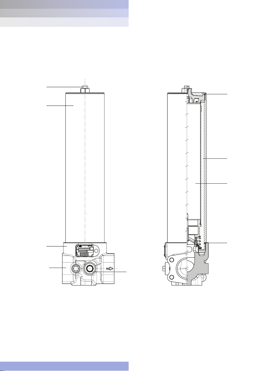
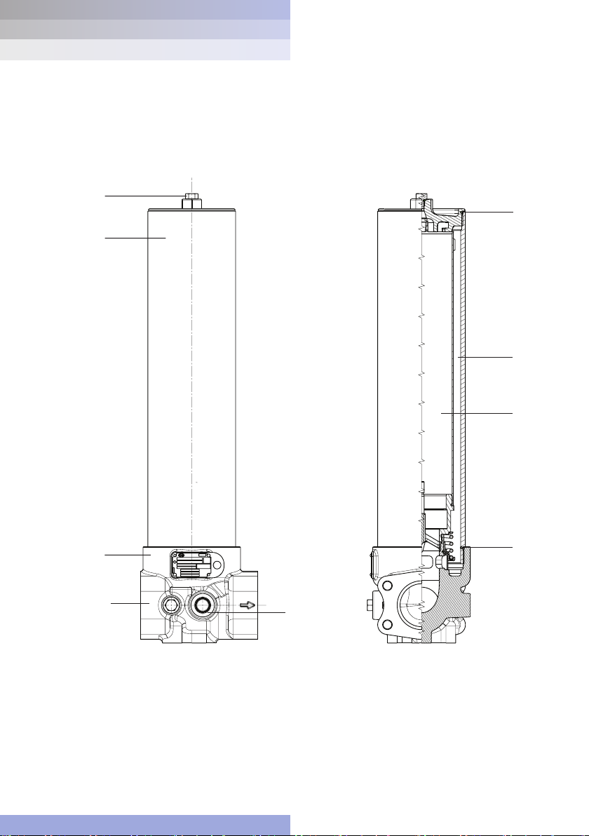
9 Parts List
List Description Quantity
1 Filter Head 1
2 Tube 1
3 Cover 1
4, 5 O-ring (cover-to-tube and head-to-tube) 2
6 Indicator or port plug kit (not shown) 1
7, 7b Vent/drain plug 2
8 Filter element 1
ENGLISH
5
Page 6
UR310
UH319
UH319 Series
service instructions
Figure 3
Z
4 HOLES FULL THREAD DEPTH AA
4 Gewindebohrungen mit Gewindetiefe AA
4 huller med gevind, dybde AA
4 taladros pasantes roscados. Profundidad A
A
4 täyskierteistä reikää, syvyys AA
4 trous taraudés de profondeur AA
4 fori completamente filettati profondità AA
4 tapgaten (met draad over volle diepte)
4st fästhål. Gänga "Z". Min gängdjup "AA"
GG
Q
HIGH PRESSURE FILTERS
UR310 Series
RETURN LINE FILTERS service instructions
Figure 2
7
3
4
2
8
1
7b
6
6
5
Page 7

UR310
UH319
UH319 Series
service instructions
Figure 3
A
HIGH PRESSURE FILTERS
UR310 Series
RETURN LINE FILTERS service instructions
Figure 3
Q
GG
Z
4 HOLES FULL THREAD DEPTH AA
4 Gewindebohrungen mit Gewindetiefe AA
4 huller med gevind, dybde AA
4 taladros pasantes roscados. Profundidad A
4 täyskierteistä reikää, syvyys AA
4 trous taraudés de profondeur AA
4 fori completamente filettati profondità AA
4 tapgaten (met draad over volle diepte)
4st fästhål. Gänga "Z". Min gängdjup "AA"
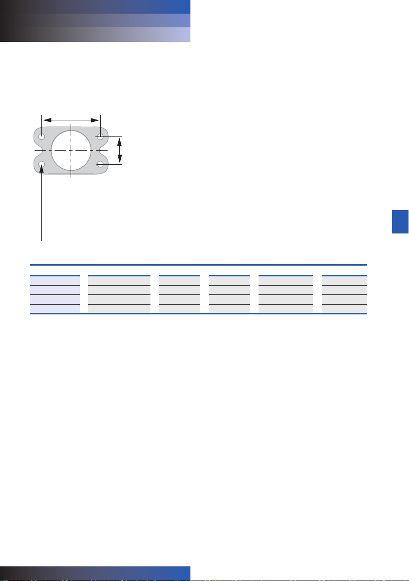
Flange Connection Details
Flange Code Nominal Tube Size GG Q Z Thread AA
D32 2" 1.688" 3.062" ½" - 13 UNC 1"
F32 2" 42.9 mm 77.8 mm M12 x 1.75 25 mm
D40 2½" 2.000" 3.500" ½" - 13 UNC 1"
F40 2½" 50.8 mm 88.9 mm M12 x 1.75 25 mm
ENGLISH
7
Page 8
UR310
RETURN LINE FILTERS
UR310 Series
service instructions
25 Harbor Park Drive
Port Washington, NY 11050
+1 516 484 3600 telephone
+1 800 289 7255 toll free US
Portsmouth - UK
+44 (0)23 9233 8000 telephone
+44 (0)23 9233 8811 fax
www.pall.com/contact
Visit us on the Web at www.pall.com
Pall Corporation has offices and plants throughout the world. For Pall representatives in your area, please go to www.pall.com/contact
Because of technological developments related to the products, systems, and/or services described herein, the data and procedures
are subject to change without notice. Please consult your Pall representative or visit www.pall.com to verify that this information
remains valid.
© Copyright 2019, Pall Corporation. Pall, and are trademarks of Pall Corporation.
® Indicates a trademark registered in the USA. Better Lives. Better Planet. and Filtration. Separation. Solution.SM are service marks
of Pall Corporation.
January 2019. Printed in England. M&ESIUR310c
Page 9
UR310
EN
CN
CN (Simplified) UR310使用说明书
UR310系列
中文
(SIMPLIFIED)
使用说明书
M&ESIUR310CN(S)c
Page 10

UR310
UR310系列
回流管过滤器 使用说明书
1 规格
滤壳材料:
过滤头和网盖:
滤管:
最高工作压力:
41巴(600 psi)
耐受压力:
62巴(900 psi)
最低爆破压力:
165巴(2400 psi)
滤芯爆破压力:
UE310滤芯最低压差 10巴 (150 psid)
工作温度范围:
带适合石油基和指定合成液体的碳氟化合物密封时,-29° C至
120°C(-20° F至250° F)
在HWCF、水油乳浊液或水乙二醇中最高60° C (140° F)
旁路阀设置选项:
1.7 ± 0.2巴(25 ± 3 psid)破裂压力
4.5 ± 0.5巴(65 ± 7 psid)破裂压力
无旁路
注意:
最低喘流不应超过正常流量的1.3倍。
密封材料:
碳氟化合物
用户应检查实际工作条件,以确保滤芯、滤壳和所有密封均适合
液体和应用且符合当地安全法规。如果需要其他信息,请联系颇
尔或批准的经销商。
球墨铸铁
碳钢
2 接收设备
滤壳和所有选装设备均单独包装,以供客户组装。请小心拆包以
免将选装零件留在将废弃的包装材料中。
3 一般信息源
3.1 对于尺寸、工作参数、总成/元件的零件号、订购信息、备
注、性能数据和规格,请参阅数据表。
3.2 本设备已经按照欧洲压力指令97/23/EC中制定的指导原则
评估并按照安全可靠的工程惯例(SEP)分类。我们在此声
明,设备满足第3条第 3节的要求,因而满足指令要求。根
据指令的条款,过滤器总成仅适用于第2组液体。
3.3 在可合理预见的条件下(包括外部火灾),可能超过容许
极限,客户必须在连接的液体系统中安装合适的保护装
置。
4 安装滤壳
4.1 过滤器可以在任何海拔高度安装,但为了便于维修,建议
垂直安装且滤管与过滤网盖朝上(UR310)或者滤管与过滤
网盖朝下(UR310H)。
4.2 拆下滤芯所需最小间隙如下所示:
4.2.1 UR310系列(网盖维护):248mm或9.8”(度
为8的滤壳);383mm或15.1”(长度为 13的滤壳)
;553mm或21.8”(长度为20的滤壳);1,061mm
或41.8”(长度为40的滤壳)。
4.2.2 UR310H系列(过滤头维护):140.97mm或5.55”
(所有长度的滤壳)。
4.2.3 UR310滤壳没有过滤器。对于滤芯安装和维修步
骤,请参阅第7节。
4.3 如有安装,带螺纹的压差设备必须拧至40 lbft或54 Nm。
所有可视指示器必须清晰可见。
注意:UR310过滤头配有加工成型的压差警告设备端口, 此端
口装有塑料装运堵头。如果未订购压差警告设备,必须拆下装运
堵头并换上B型堵塞器(P/N HA9000-A104Z),然后使用40 lbft或
54 Nm力矩拧紧。
注意:在下O型环凹槽中安装统一尺寸的 -014 O型环前,切勿
使用堵头堵住端口,否则,旁路将出现小水流,致使污染物流
到滤芯下游。
注意:
切勿操作过滤器,否则警告设备端口会闭合。
4.4 使用1/2” - 20UNF - 2B(A或 D端口)或M12 x 1.75 -
6H(C或F端口)螺栓将过滤器总成装在过滤头安装垫片
上。使用20 - 25 lbft或 27 - 34 Nm力矩拧紧螺栓。
4.5 如果可能回流,在过滤器下游安装止回阀。
4.6 如需在系统不停机时维护过滤器,请使用另一管道/阀门安
装滤罩,以使过滤器总成完全旁通。此系列不用于双路或
维修旁路结构。
注意:
从滤芯回流会导致过滤器损坏。
注意:建议尽量在离端口连接处近的位置安装管道支架,以将
外部负载降至最低。此过滤器总成不得与用户的接地系统电气隔
离。此过滤器总成必须通过以下方法接地:将用户的接地系统接
至入水/出水口连接处。
4.7 将管路或软管连接滤壳入水和出水口。
警告:
使用兼容所提供端口的接头或适配器,如铭牌和数据表中零
件号所示:使用错误接头或适配器可导致滤罩或歧管出现故
障,致使压力下降、系统出现故障或人员受伤。
10
Page 11

UR310
UR310系列
回流管过滤器 使用说明书
注意:可在滤壳上喷漆。滤壳上的涂层是合适的底漆。在外壳上
喷漆时,遮盖压差警告设备和铭牌。
4.8 将过滤器放气
4.8.1 UR310(网盖维护):将过滤器顶部的放气塞(7)拧开一圈
半对过滤器放气。慢慢运行系统并装满过滤器,直至所有
空气通过放气塞,然后使用12 ft/lb或16 Nm 力矩拧紧放气
塞。
4.8.2 UR310H(过滤头维护):将过滤头上的放气塞(7b)拧开一
圈半对过滤器放气。慢慢运行系统并装满过滤器,直至所
有空气通过放气塞,然后使用12 ft/lb or 16 Nm力矩拧紧
放气塞。
对系统完全加压并检查是否泄漏;如果泄漏,请参阅第5节。
注意:
滤罩未完全放气将增加系统液体中溶解的空气含量,从而缩
短液体寿命并导致系统中出现其他问题。
5 日常维护
5.1 除定期监测压差警告设备外,在正常情况下,颇尔过滤器
无需特别注意。安排最长每六个月更换一次滤芯并备足备
用滤芯。
5.2 如果发现从外部泄漏,请更换泄漏处的O型环。如果仍然
泄漏,请检查密封面是否划破或裂开;更换损坏的零件。
5.3 在需要更换滤芯或“冷启动”状态下液体粘度较高时,压差
设备发出警告。如果出现“冷启动”状态,请参阅6.2和 6.3
节。
5.4 脏污的系统可能很快堵塞新滤芯,特别是在使用颇尔高效
过滤介质时。此时,可能需要更换一次或两次原装滤芯,
以便保持滤芯的寿命。如果滤芯寿命短或压差较高,过滤
器可能不够大;请参阅产品手册中的尺寸和选择章节或联
系当地颇尔代表。
5.5 确保滤芯更换标签干净、未损坏。将字迹模糊的标签更换
为相应的新标签。
6 压差设备
对于尺寸、工作参数、零件编号、订购信息和规格,应参考产
品手册。
6.1 在需要更换滤芯或液体粘度“冷启动”状态下较高时,压差
设备发出信号。
6.2 如果不锈钢可视指示器(若安装)在“冷启动”时发出信号
(红色按钮弹起5mm3/16”),在达到正常工作温度时,
请按下按钮重置。如果指示器在重置后发出信号,请更换
滤芯。如果黄铜可视指示器(若安装)在“冷启动”时发出
信号(指示器内标志的变红),在达到正常工作温度时,
则会自动重置。如果指示器在达到正常工作温度后仍然发
出信号,请更换滤芯。
注意:‘P’可视指示器选件具有热锁定和手动重置功能。在0° C
(32° F)以下和29° C (80° F) 以上时,不会发出信号。
6.3 建议使用正指示(绿灯)和负指示(红灯,提示滤芯变
脏)有效监测滤芯的寿命。
6.4 如果电气开关在冷启动时发出信号(例如,红灯亮起),
则继续运行,直至信号(红灯)在系统升至正常工作温
度时消失。此功能可在运行过程中作为“预热”指示。如果
警告信号(红灯)仍存在或在系统升温后出现,请更换滤
芯。
电气连接和额定值取决于所选指示器。以下仅列出典型值:
110 VAC = 4A(感应式),
220 VAC = 4A(感应式),
28 VDC = 3A(感应式),
48 VDC = 1A(感应式),
125 VDC = 0.25A(感应式),
最高涌流 - 24安
Underwriter’s lab. Inc.列出压力开关(微动开关)选件的如下
额定值:
250 VAC下4安
220 VDC下0.25安(电阻式)
110 VDC下0.50安(电阻式)
电气压差开关运行:
在超过预设压差时,从“常闭(NC) - 共用地线”切换至“常开(NO)
- 共用地线”。
当压差降至预设值以下时,从“常开(NO) - 共用地线”恢复为“常闭
(NC) - 共用地线”。
4A(电阻式)
4A(电阻式)
5A(电阻式)
1.5A(电阻式)
0.5A(电阻式)
图1 - 开关电路图
常闭(NC)
引脚2
常开(NO)
引脚3
有关连接详情,请参阅各指示器选项。
压差低
压差高
共用地线
引脚1
中文
(SIMPLIFIED)
11
Page 12
UR310
UR310系列
回流管过滤器 使用说明书
7 滤芯维修
在维修时,必须洗去过滤器总成外表面上的所有灰尘。
必须使用不会产生危险的合适工具维修。
在空气可能引发爆炸时,切勿维修。
注意:
在提示或达到指定间隔(最长六个月)时更换滤芯。未更换
滤芯将导致过滤器不会有效过滤。
有关合适替换滤芯系列的零件号,请参阅备件清单(第9节)。
按以下步骤拆卸和更换滤芯:
7.1 关闭系统并减压。
警告:
在维修滤芯前未对过滤器减压可导致液体大量流失,使设备
损坏,人员也可能受伤。
7.2 UR310系列(网盖维护):
将过滤器顶部的放气塞(7)拧开一圈半。
打开过滤头上的排水阀(7b)并将液体排入合适的废物桶中。
更换排水阀并使用12ft/lb或16Nm力矩拧紧。从滤管(2)上逆
时针(从上往下看)拧下网盖(3)。首次拆卸时,可能需要
使用1”套筒扳手拧动网盖(3)上的六角螺钉。
注意:Ur310系列总成配有颇尔的‘自动抽拉’滤芯拆取装置以便
拆卸滤芯。拆下盖板后,滤芯底盖上的连接片卡入盖板上的钩子
中,滤芯被自动从接套中拉出。
7.3 UR310H系列(过滤头维护):
打开滤杯总成(滤管和网盖)底部的排水阀(7)并将滤杯中
的液体排入合适的废物桶中。更换排水阀并使用12 ft/lb或
16 Nm力矩拧紧。从过滤头(1)上逆时针(从下往上看)拧
下滤杯总成(2和3)。首次拆卸时,可能需要使用1”套筒
扳手拧动网盖(3)上的六角螺钉。
7.4 更换滤芯(UE310系列):拆下滤芯(8)(若已安装)并仔
细检查内表面(流进和流出滤芯)是否变脏。正常情况下
应没有污渍,但可见污渍或颗粒是系统组件故障的预警。
丢弃滤芯及其O型环。滤芯不可清洁。尝试清洁滤芯可导
致滤材性能下降,使脏污液体流过滤芯。
警告:
切勿尝试清洁或二次使用滤芯。
只能使用颇尔生产的替换滤芯。使用其他滤芯可能导致产
品保修失效。
7.5 未安装滤芯时,切勿运行系统。
UR310系列: 检查并确保网盖(3)和滤管(2)间的O型环(4)
未损坏。
UR310H系列: 检查并确保网盖(2)和滤管(1)间的O型环
(5)未损坏。
使用滤芯端盖上零件号标出的替换滤芯。
7.6 使用干净的系统液体润滑滤芯O型环。将滤芯重新装入滤
壳总成。使用干净的系统液体稍微润滑网盖与过滤头或滤
管与过滤头(若使用)间的O型环并重新组装滤壳,直至
拧到最后一圈螺纹。只能用手拧紧。
7.7 在过滤器中加满水以便放出气体,直至所有空气通过放气
塞(7),然后使用12 lb/ft或16Nm拧紧放气塞。按照4.8节内
容检查是否泄漏。
7.8 更换滤芯后,确保压差设备已重置。黄铜可视指示器、电
气开关和不锈钢电子开关自动重置。在系统达到正常工作
温度时,请检查并确保电气开关和/或可视警告按钮/标志
未发出信号。如果冷启动状态导致可视指示器发出信号,
请按照第6节内容再次重置。
8 保修、责任限制和补救措施
除非另有说明,我们不提供产品适销性或特定用途适用性的任何
保修,也不提供任何明示或暗示保证。
自销售方供货起十二个月或使用三千小时内(“保修期间”,以先
到者为准),在正确安装和保养以及按额定要求、规范和设计
条件使用的条件下,销售方保证销售方生产的产品没有材料和
工艺缺陷。作为说明而非限制,销售方对滤芯的使用寿命不提
供保证,因为这不在销售方的控制范围内且取决于安装过滤器
的系统条件。
销售方的保证责任仅限于更换(FOB原发货点)、维修保修期间
出现故障的产品(由销售方判定)或为其提供信用证。购买方要
尽快书面通知销售方提出索赔,并为销售方提供检验和测试涉及
缺陷的产品。购买方要为销售方提供产品发票原件复印件,预先
支付将产品退回销售方工厂或销售方指定地点产生的运费。所有
索赔都必须提供全部详情,包括适用的系统操作条件。
对于在销售方工厂外(销售方或销售方授权的经销商除外)改装
的任何产品,销售方概不负责;至于授权经销商改装的产品,销
售方仅对授权经销商按照其书面说明组装的产品负责。对于出现
误用、滥用、不当安装、应用、操作、保养或维修、改装以及使
用、储存、运输或搬运过失的产品,销售方概不负责。
对于与本产品生产、包装、交付、储存、使用、不当使用或未使
用相关的任何偶然、必然或其他损失,销售方概不负责。
12
Page 13

UR310
UR310系列
回流管过滤器 使用说明书
9 零件清单
列表
1
2
3
4、5
6
7、7b
8
描述
过滤头
滤管
网盖
O型环(过滤头与滤杯间)
指示器或塞子套件(未显示)
放气/排水塞
滤芯
数量
1
1
1
2
1
2
1
中文
(SIMPLIFIED)
13
Page 14

UH319
UH319 Series
service instructions
Figure 3
Z
4 HOLES FULL THREAD DEPTH AA
4 Gewindebohrungen mit Gewindetiefe AA
4 huller med gevind, dybde AA
4 taladros pasantes roscados. Profundidad A
A
4 täyskierteistä reikää, syvyys AA
4 trous taraudés de profondeur AA
4 fori completamente filettati profondità AA
4 tapgaten (met draad over volle diepte)
4st fästhål. Gänga "Z". Min gängdjup "AA"
GG
Q
HIGH PRESSURE FILTERS
UR310
UR310系列
回流管过滤器 使用说明书
图2
7
3
4
2
8
1
7b
6
14
5
Page 15
UH319
UH319 Series
service instructions
Figure 3
A
HIGH PRESSURE FILTERS
UR310
UR310系列
回流管过滤器 使用说明书
图3
Q
GG
Z
4 HOLES FULL THREAD DEPTH AA
4 Gewindebohrungen mit Gewindetiefe AA
4 huller med gevind, dybde AA
4 taladros pasantes roscados. Profundidad A
4 täyskierteistä reikää, syvyys AA
4 trous taraudés de profondeur AA
4 fori completamente filettati profondità AA
4 tapgaten (met draad over volle diepte)
4st fästhål. Gänga "Z". Min gängdjup "AA"
法兰连接详情
法兰代码
D32 2” 1.688” 3.062” ½” - 13 UNC 1”
F32 2” 42.9 mm 77.8 mm M12 x 1.75 25 mm
D40 2½” 2.000” 3.500” ½” - 13 UNC 1”
F40 2½” 50.8 mm 88.9 mm M12 x 1.75 25 mm
标称滤管尺寸
GG
Q
Z螺纹
AA
中文
(SIMPLIFIED)
15
Page 16

UR310
UR310系列
回流管过滤器 使用说明书
25 Harbor Park Drive
Port Washington, NY 11050
电话:+1 516 484 3600
美国免费电话:+1 800 289 7255
Portsmouth - UK
电话:+44 (0)23 9233 8000
传真:+44 (0)23 9233 8811
www.pall.com/contact
欢迎访问我们的网站:www.pall.com
颇尔公司的办事处和工厂遍布世界各地。如需了解颇尔当地代表,请访问www.pall.com/contact
由于所述产品、系统和/或服务不断采用新技术,数据和程序可能随时变更,恕不另行通知。请咨询您的颇尔代表或访问
www.pall.com,确认本资料信息是否有效。
© 版权所有2019,颇尔公司。Pall和 均是颇尔公司的商标。
®表示美国注册商标。Better Lives.Better Planet 以及 Filtration.Separation.Solution.SM均为颇尔公司的服务标志。
2019年1月。 英国印制。M&ESIUR310CN(S)c
Page 17

UR310
EN
CN
UR310系列
CN (Traditional)
中文
UR310使用說明書
中文
(TRADITIONAL)
使用說明書
M&ESIUR310CN(T)c
Page 18

UR310
UR310系列
返回管線過濾器 使用說明書
1 規格
外殼材質:
頭部及外罩:
管件:
最大操作壓力:
41 bar (600 psi)
驗證壓力:
62 bar (900 psi)
最小爆裂壓力:
165 bar (2400 psi)
濾芯爆裂壓力:
UE310濾芯至少10 bard (150 psid)壓差
操作溫度範圍:
-29° C 至 120° C (-20° F 至 250° F),有氟碳化合物密封時,
用於石油基及指定合成液體
最大60° C (140°F),HWCF、水油乳化液或水-乙二醇液體時。
旁通閥設定選項:
1.7 ± 0.2 bard (25 ± 3 psid)開啟壓力(cracking pressure)
4.5 ± 0.5 bard (65 ± 7 psid)開啟壓力(cracking pressure)
無旁通
注意:
最大湧升流量不得超過正常流量的1.3倍。
密封:
氟碳化合物
使用者須檢查實際操作條件,以確保元件、外殼及所有密封與
流體及應用相容,且符合當地安全規定。如需更多資訊,請洽詢
Pall或授權經銷商。
延性鑄鐵
碳鋼
2 收到設備
過濾器外殼及其他選購設備均為獨立包裝,待由客戶組裝。拆封
時應小心,並確保選購物品未遺落在欲丟棄的包裝內。
3 一般資訊來源
3.1 尺寸、操作參數、組件/元件料號、訂購資訊、注意事
項、性能資料及規格,參見規格表。
3.2 本設備已依據歐洲壓力指令97/23/EC規定之指導方針
進行評估,並已歸入完善的工程作業規範S.E.P (sound
engineering practice)中。設備符合第3條第3款要求,因此
符合指令要求,特此聲明。按本指令之規定,過濾器組件
僅適用於第2類(group 2)流體。
3.3 在合理可預見的情況下包含外部火災在內,可能超過允許
的極限值,客戶必須在相連的流體系統中安裝適當的保護
裝置。
4 安裝外殼
4.1 過濾器能以任何姿態安裝,但為方便維修,建議垂直安
裝,過濾器管件及外罩朝上(UR310)或過濾器管件及外罩朝
下。
4.2 取出元件所需之最小間距如下:
4.2.1UR310系列(從外罩維修):外殼長度8為
248mm (9.8”)、外殼長度13為383mm (15.1”)、
外殼長度20為553mm (21.8”)、外殼長度40為
1061mm (41.8”)。
4.2.2UR310H系列(從頭部維修):所有長度均為
140.97mm (5.55”)。
4.2.3提供的UR310外殼不含濾芯。濾芯安裝及維修程
序,參見第7章。
4.3 安裝螺紋壓差裝置時,必須鎖緊至扭力40 lbft 或 54 Nm。
所有目視指示必須清楚可見。
備註:UR310頭部出廠時附有機械加工的壓差警告裝置接口,並
裝有塑膠運輸塞。若未訂購壓差警告裝置,則必須取下運輸塞,
並安裝B型孔塞(blanking plug, P/N HA9000-A104Z),鎖緊扭力
為40lbft 或 54 Nm。
備註:務必先在下O形環凹構中安裝均勻尺寸的-014 O形環後,
才能將孔塞裝入此接口中,否則會形成少量旁通流,而導致濾
芯下游污染。
注意:
未將警告裝置接口密封前,切勿操作過濾器。
4.4 將1/2” - 20UNF - 2B(A或D接口)或M12 x 1.75 -6H
(C或F接口)螺栓置於頭部安裝板孔內,固定過濾器組件
的位置。螺栓鎖緊扭力為20 - 25 ft/lb 或 27 - 34 Nm。
4.5 若有反向流的可能性,則應在過濾器下游安裝止回閥。
4.6 若過濾器需要維護且不得關閉系統,則應利用額外的管
件/閥門安裝過濾器外殼,以便能旁通整個過濾器組件。
本系列不適用於雙工或維修旁路配置。
注意:
反向流通濾芯會造成損壞。
備註:管件支撐應儘可能靠近接口連接處,以將外部負荷降至最
低。本過濾器組件與使用者的接地系統之間不得為電氣隔離。必
須藉由將使用者的接地系統與其中一個入口/出口連接處連接,
將本過濾器組件接地。
4.7 將管線或軟管連接至外殼出口及入口接口。
警告:
使用與隨附接口相配的接頭或轉接頭,參見銘牌上之料號及
規格表所示:使用錯誤的接頭或轉接頭可能造成過濾器外殼
或歧管失效,導致壓力損失、系統故障或人員受傷。
18
Page 19

UR310
UR310系列
返回管線過濾器 使用說明書
備註:可選擇塗裝過濾器外殼,過濾器外殼的塗層是合適的底
漆。如欲進行外殼塗裝,則應先遮住壓差警告裝置及銘牌。
4.8 排空過濾器
4.8.1 UR310(從外罩維修):將過濾器頂部的通氣塞(7)旋開一
圈半,以排空過濾器。輕搖系統並填充過濾器,直到所有
空氣經由旋塞排出後,再以12ft/lb 或 16 Nm的扭力鎖緊旋
塞。
4.8.2 UR310H(從頭部維修):將頭部的通氣塞(7b)旋開一圈
半,以排空過濾器。輕搖系統並填充過濾器,直到所有空
氣經由旋塞排出後,再以12ft/lb 或 16 Nm的扭力鎖緊旋
塞。
將系統完全加壓檢查洩漏情況,如有洩漏,參見第5節。
注意:
若未能確實排空過濾器外殼,將造成溶解在系統流體內的空
氣量增加,進而縮短流體壽命並可能導致其他系統問題。
5 日常維護
5.1 Pall過濾器除定期監測壓差警告裝置外,一般不需要特別
注意。安排每六個月或更早更換濾芯,並備妥充足的備用
濾芯。
5.2 若發現外部洩漏,則更換洩漏處的O形環。若持續洩漏,
檢查密封表面是否有刮痕或裂縫,更換有瑕疵的零件。
5.3 當濾芯需要更換或因在「冷啟動」時高流體黏度的情況
下,則壓差裝置動作。若「冷啟動」狀態持續,參見6.2及
6.3節。
5.4 髒污的系統可能很快堵塞新濾芯,特別是在使用Pall高效
過濾介質時。一開始可能需要更換一次或兩次濾芯,以穩
定濾芯壽命。若濾芯壽命短或壓差過大,可能表示過濾器
尺寸過小,請參閱產品說明文件的尺寸選擇章節,或洽詢
當地Pall代表。
5.5 確認濾芯更換標籤乾淨且未受損。若標籤難以辨認,則應
更換適當的新標籤。
6 壓差裝置
應參閱產品說明文件中的尺寸、操作參數、料號、訂購資訊及
規格。
6.1 當濾芯需要更換或因在「冷啟動」時高流體黏度的情況
下,則壓差裝置動作。
6.2 若裝有不鏽鋼目視指示器且在「冷啟動」期間動作(紅色
按鈕延伸5mm、3/16”),則在達到正常操作溫度後按下
按鈕以復位。若指示器在復位後動作,則更換濾芯。若裝
有黃銅目視指示器且在「冷啟動」期間動作(指示器內的
旗標變成紅色),則會在達到正常操作溫度時自動復位。
若在達到正常操作溫度後仍處於動作狀態,則更換濾芯。
備註:‘P’目視指示器選購件具有溫度鎖定及手動復位。0° C (32°
F)以下無訊號,29° C (80° F)以上有訊號。
6.3 建議同時使用正常指示(綠燈)及異常指示(紅燈表示濾
芯變髒),以有效監測濾芯壽命。
6.4 若冷啟動期間電氣開關動作(例如亮紅燈),則繼續操作
直到系統加熱至正常操作溫度時,訊號(紅燈)消失。此
功能可作為操作程序中的「預熱」指示。若系統升溫後警
告訊號(紅燈)仍持續或出現,則更換濾芯。
電氣連接及額定值取決於選用的指示器。以下僅顯示典型數值:
110 VAC = 4A(電感),
220 VAC = 4A(電感),
28 VDC = 3A(電感),
48 VDC = 1A(電感),
125 VDC = 0.25A(電感),
最大湧升-24安培。
Underwriter’s lab. Inc.列名壓力開關(微動開關)的額定值選
項包括:
4安培,250 VAC時
0.25安培(電阻),220 VDC時
0.50安培(電阻),110 VDC時
電動壓差開關操作:
超過預設壓差時,連續性從常閉(NC)-共接點切換至常開(NO)
-共接點。
若壓差降至預設值以下,則連續性從常開(NO)-共接點切回至常
閉(NC)-共接點。
4A(電阻)
4A(電阻)
5A(電阻)
1.5A(電阻)
0.5A(電阻)
圖1、開關電路圖
ᐌ䭝(NC)
㝇2
ᐌ䭟(NO)
㝇3
詳細連接說明參見個別指示器選項。
ԢວᏂ
催ວᏂ
݅咲
㝇1
中文
(TRADITIONAL)
19
Page 20

UR310
UR310系列
返回管線過濾器 使用說明書
7 濾芯維修
維修時,必須清潔過濾器組件外部表面,以去除堆積的灰塵。
必須以不會造成危險的合適工具進行維修。
不得在可能爆炸的環境中進行維修。
適用更換濾芯系列之品項編號,參見維修零件表(第9節)。按
照以下說明取出並更換濾芯:
注意:
須依指示或按照規定的間隔時間(最長六個月)更換濾芯。
未更換濾芯將導致過濾器持續旁通。
7.1 關閉系統並降壓。
警告:
維修濾芯前若未先將過濾器降壓,可能導致流體爆炸損失、
設備受損及人員受傷。
7.2 UR310系列(從外罩維修):
將過濾器頂部的通氣塞(7)旋開一圈半。
打開過濾器頭部的排放塞(7b),並將流體排至合適的廢棄
物容器中。更換並鎖緊排放塞至12ft/lb 或 16Nm。從上
方觀看時,逆時針旋轉鬆開外罩(3)並從管件(2)取下。一
開始可能須使用一個1”的套筒扳手,以鬆開外罩(3)上的
六角螺栓。
備註:UR310系列組件配備Pall的「自動拉出(Auto-Pull)」濾芯抽
取機構,以便取出濾芯。取下護蓋時,濾芯端蓋上的扣環卡到護
蓋內的鉤子上,自動從短管中拉出濾芯。
7.3 UR310H系列(從頭部維修):
打開本體組件(管件及護罩)底部的排放塞(7),將本體內
的流體排放至合適的廢棄物容器中。更換並鎖緊排放塞至
12 ft/lb 或 16 Nm。從下方觀看時,逆時針旋轉鬆開本體
組 件 (2及3)並從頭部(1)取下。一開始可能須使用一個1”的
套筒扳手,以鬆開外罩(3)上的六角螺栓。
7.4 更換濾芯(UE310系列):若已裝有濾芯(8),取出並仔
細檢查內部表面(通過濾芯的流向為由內向外)是否有明
顯的污染情況。正常情況下不應出現髒污,但若發現髒污
或粒子可能是系統元件故障的早期警告。丟棄濾芯及O形
環。濾芯無法清潔。試圖清潔濾芯可能導致過濾介質劣
化,並使髒污的流體通過濾芯。
7.5 切勿在未安裝濾芯的情況下運轉系統。
針對UR310系列:確認外罩(3)與管件(2)之間的O形環(4)
未受損。
針對UR310H系列:確認管件(2)與頭部(1)之間的O形環(5)
未受損。
使用與濾芯端蓋上所示料號相同的濾芯進行更換。
7.6 使用乾淨的系統流體潤滑濾芯的O形環。將濾芯裝回殼體
組件內。用乾淨的系統流體略微潤滑外罩與頭部間或管件
與頭部間的O形環,並裝回外殼直到螺紋鎖到底。只能用
手鎖緊。
7.7 藉由填充過濾器以排空過濾器,直到所有空氣經由通氣塞
(7)排出,並以12 lb/ft 或 16Nm的扭力鎖緊通氣塞。按照
4.8節檢查洩漏。
7.8 更換濾芯後,確認壓差裝置復位。黃銅目視及電動與不鏽鋼
電動開關自動復位。當系統達到正常操作溫度時,確認電
動開關及/或目視警告鈕/旗標無動作。若目視指示器因
冷啟動狀態而動作,則按照第6節再次復位。
8 保固、責任限制及補救措施
就產品而言,除文中所述外,不保證任何特定用途之可售性
(MERCHANTABILITY)或合適性,亦沒有任何其他明示或暗示
之保證。
自賣方交貨日起12個月內或使用三千小時內,以先到者為準(
「保固期」),賣方保證由賣方製造的產品,在正確安裝及維護
並按照額定值、規格及設計條件操作之情況下,無任何材料及工
藝上的缺失。藉由以說明而非限制之方式,賣方無法保證濾芯的
使用壽命,因為此超出賣方的控制範圍,且取決於裝有過濾器之
系統的狀態。
針對保固期內有缺失的產品,賣方的保固責任僅限於更換(FOB
原始出貨地點)、檢修或給予折抵額度(由賣方自行決定)。買
方須立即以書面方式通知賣方任何事由,並讓賣方有機會檢驗及
測試宣稱有缺失的產品。買方須提供賣方產品正本發票的副本,
並預付將產品送回賣方工廠或賣方指定其他地點的所有運費。所
有事由必須隨附完整詳細說明,包含適用之系統操作情況。
賣方不為任何在賣方工廠以外、非賣方或賣方授權經銷商所做
的產品變更負任何責任,若為由授權經銷商變更者,則僅限於經
銷商按照賣方書面說明組裝之產品。賣方亦不為任何因誤用、濫
用、不當安裝、應用、操作、維護或檢修、變更、意外或疏於使
用、儲存、運輸或處理之產品負任何責任。
不論在任何情況下,賣方皆不為因任何產品之製造、包裝、交
貨、儲存、使用、誤用或未使用或任何其他原因造成之損害、事
故、後果或其他情況負任何責任。
警告:
切勿試圖清潔或重複使用濾芯。
只能更換PALL原廠濾芯。使用替代濾芯可能導致產品保固
失效。
20
Page 21

UR310
UR310系列
返回管線過濾器 使用說明書
9 零件表
編號
1
2
3
4, 5
6
7, 7b
8
說明
過濾器頭部
管件
外罩
O形環(頭部-本體之間)
指示器或接口孔塞套件(未顯示)
通氣/排放塞
濾芯
數量
1
1
1
2
1
2
1
中文
(TRADITIONAL)
21
Page 22
UH319
UH319 Series
service instructions
Figure 3
Z
4 HOLES FULL THREAD DEPTH AA
4 Gewindebohrungen mit Gewindetiefe AA
4 huller med gevind, dybde AA
4 taladros pasantes roscados. Profundidad A
A
4 täyskierteistä reikää, syvyys AA
4 trous taraudés de profondeur AA
4 fori completamente filettati profondità AA
4 tapgaten (met draad over volle diepte)
4st fästhål. Gänga "Z". Min gängdjup "AA"
GG
Q
HIGH PRESSURE FILTERS
UR310
UR310系列
返回管線過濾器 使用說明書
圖2
7
3
4
2
8
1
7b
6
22
5
Page 23

UH319
UH319 Series
service instructions
Figure 3
A
HIGH PRESSURE FILTERS
UR310
UR310系列
返回管線過濾器 使用說明書
圖3
Q
GG
Z
4 HOLES FULL THREAD DEPTH AA
4 Gewindebohrungen mit Gewindetiefe AA
4 huller med gevind, dybde AA
4 taladros pasantes roscados. Profundidad A
4 täyskierteistä reikää, syvyys AA
4 trous taraudés de profondeur AA
4 fori completamente filettati profondità AA
4 tapgaten (met draad over volle diepte)
4st fästhål. Gänga "Z". Min gängdjup "AA"
法蘭連接詳細說明
法蘭編號
D32 2” 1.688” 3.062” ½” - 13 UNC 1”
F32 2” 42.9 mm 77.8 mm M12 x 1.75 25 mm
D40 2½” 2.000” 3.500” ½” - 13 UNC 1”
F40 2½” 50.8 mm 88.9 mm M12 x 1.75 25 mm
標稱管件尺寸
GG
Q
Z螺紋
AA
中文
(TRADITIONAL)
23
Page 24

UR310
UR310系列
返回管線過濾器 使用說明書
25 Harbor Park Drive
Port Washington, NY 11050
+1 516 484 3600 電話
+1 800 289 7255 美國免費電話
Portsmouth - UK
+44 (0)23 9233 8000 電話
+44 (0)23 9233 8811 傳真
www.pall.com/contact
我們的網站:www.pall.com
Pall Corporation在全球都有辦公室和工廠。有關您所在地區的Pall Corporation 代表,請參閱網站:www.pall.com/contact。
由於文中提及的相關產品、系統及/或服務的技術開發其資料和程序可能變更,恕不另行通知。請洽詢您的Pall Corporation代表或
連結至www.pall.com,以確認本資訊是否仍有效。
© 版權2019,Pall Corporation、Pall及為Pall Corporation的商標。
® 表示美國註冊商標。Better Lives. Better Planet and Filtration. Separation. Solution.SM為 Pall Corporation的服務標章。
2019年1月。 英國印刷。M&ESIUR310CN(T)c
Page 25

UR310
EN
DE
CN
Baureihe UR310
DE UR310 Wartungsanleitung
DEUTSCH
Wartungsanleitung
M&ESIUR310DEc
Page 26

UR310
RÜCKLAUFFILTER
Baureihe UR310
Wartungsanleitung
1. Spezifikationen
Gehäusematerialien:
Kopf und Deckel: Kugelgraphitguß
Rohr: C-Stahl
Maximaler Betriebsdruck:
41 bar
Prüfdruck:
62 bar
Minimaler Berstdruck:
165 bar
Filterelementberstdruck:
UE310 Element, 10 bar Differenzdruck
Betriebstemperaturbereich:
-29° C bis + 120° C (-20° F bis 250° F) mit FKM-Dichtungen für
mineralische und synthetische Flüssigkeiten
maximal 60° C (140° F) bei HWCF, Wasser-Öl-Emulsionen bzw.
Wasser-Glykol Flüssigkeiten
Öffnungsdruck der Bypassventile:
Bypassöffnungsdruck 1,7 ± 0,2 bar
Bypassöffnungsdruck 4,5 ± 0,5 bar
Ohne Bypass
VORSICHT:
Der maximale Durchsatz sollte nicht mehr als das 1,3fache des normalen Volumenstroms betragen.
Dichtungen:
Fluorkautschuk (FKM)
Bitte prüfen Sie die vorhandenen Betriebsbedingungen
vor Einbau des Filters. Stellen Sie sicher, dass Gehäuse,
Filterelement und Dichtungen mit der Flüssigkeit verträglich
und für die Anwendung geeignet sind und den im Betrieb
geltenden Sicherheitsvorschriften entsprechen. Für weitere
Informationen wenden Sie sich bitte an Pall oder einen autorisierten Händler.
2 Anlieferung der Filter
Das Filtergehäuse und alles weitere Zubehör sind einzeln
verpackt und vom Kunden zu montieren. Bitte packen Sie die
Teile vorsichtig aus und vergewissern Sie sich, dass keine
Einzelteile in der Verpackung zurückgeblieben sind, bevor sie
diese entsorgen.
3 Allgemeine Informationen
3.1 Abmessungen, Betriebsdaten, Komplettfilter- und
Elementbezeichnungen, Bestellinformationen,
Anmerkungen, Leistungsdaten und Spezifikationen entnehmen Sie bitte dem Datenblatt.
3.2 Dieser Filter wurde nach den Richtlinien der
Europäischen Druckgeräterichtlinie 97/23/EC bewertet
und entspricht „guter Ingenieurpraxis“. Wir erklären, dass der Filter die Anforderungen von Artikel 3,
Abschnitt 3 erfüllt und somit den Normanforderungen
entspricht. Nach den Bestimmungen dieser Norm ist der
Komplettfilter daher nur für Flüssigkeiten der Gruppe 2
geeignet.
3.3 Wenn die zulässigen Grenzwerte unter vorhersehbaren
Bedingungen, einschließlich Bränden im Außenbereich,
überschritten werden könnten, müssen vom Kunden
geeignete Schutzeinrichtungen innerhalb des angeschlossenen Flüssigkeitssystems installiert werden.
4 Einbau des Gehäuses
4.1 Der Filter kann in jeder beliebigen Lage eingebaut werden,
aber zur Erleichterung der Wartungsarbeiten ist es empfehlenswert, den Filter senkrecht, mit dem Rohrkörper und
dem Deckel nach oben zeigend (UR310) bzw. nach unten
zeigend (UR310H) einzubauen.
4.2 Sehen Sie oberhalb des Deckels einen Mindestfreiraum
zum Elementwechsel vor:
4.2.1 Baureihe UR310 (Deckel-Betrieb): 248mm (9,8") für
4.2.2 Baureihe UR310H (Head Service): 141 mm für alle Längen.
4.2.3 Das UR310 Gehäuse wird ohne Filterelement geliefert.
4.3 Werden Differenzdruckanzeigen eingebaut, ziehen Sie diese
HINWEIS: Der UR310 Filterkopf wird mit einer
Differenzdruckanzeigenbohrung geliefert, die mit einem Transportstopfen
aus Kunststoff verschlossen ist. Wenn keine Differenzdruckanzeige
bestellt wurde, muss der Transportstopfen entfernt und durch einen
Blindstopfen des Typs ‚B‘ (Teilenummer HA9000A104Z) ersetzt werden,
der mit einem Drehmoment von 54 Nmangezogen werden muss.
HINWEIS: Vor Einbau eines Blindstopfens in diesen Anschluss sicherstellen, dass ein O-Ring der Größe 2-014 in die untere Ringnut einsetzt
ist. Andernfalls entsteht ein kleiner Bypass, wodurch Verschmutzung
auf die Reinseite des Filters gelangen kann.
4.4 Montieren Sie die Filtereinheit mit 1/2" - 20UNF - 2B
4.5 Bei Gefahr von Rückfluss installieren Sie nach dem Filter
4.6 Installieren sie das Filtergehäuse mit zusätzlichen
HINWEIS: Zum Minimieren der externen Belastungen sind
Rohrstützen in unmittelbarer Nähe zu den Anschlüssen zu installieren. Diese Filtereinheit darf nicht elektrisch vom Erdungssystem
des Kunden isoliert werden. Die Filtereinheit muss durch
Verbinden entweder des Eintritts- oder des Austrittsanschlusses
mit dem Erdungssystem des Kunden geerdet werden.
4.7 Schließen Sie die Rohrleitungen oder Schläuche an die
Gehäuse der Länge 8, 383mm (15,1") für Gehäuse
der Länge 13, 553mm (21,8") für Gehäuse der Länge
20 und 1061mm (41,8") für Gehäuse der Länge 40.
Informationen zum Einbau bzw. Wechsel des Elements
entnehmen Sie bitte Abschnitt 7.
bei der Montage mit einem Drehmoment von 54Nm an. Alle
optischen Anzeigen müssen gut sichtbar sein.
VORSICHT:
Nehmen Sie den Filter nur in Betrieb, wenn die
Differenzanzeigenbohrung verschlossen ist.
Schrauben (Anschlüsse ‚A‘ oder ‚D‘) oder M12 x 1,75 - 6H
Schrauben (Anschlüsse ‚C‘ oder ‚F‘) an den dafür vorgesehenen Bohrungen im Filterkopf. Ziehen Sie die Schrauben
mit einem Drehmoment von 30,5 +-0,5Nman.
ein Rückschlagventil.
Rohrleitungen und Ventilen, so dass im Fall von notwendigen Wartungsarbeiten an der Filtereinheit der gesamte Fluss
um die Filtereinheit herumgeleitet werden kann, ohne dass
das System abgeschaltet werden muss. Diese Baureihe ist
nicht als Duplex- oder Service-Bypass-Filter erhältlich.
VORSICHT:
Durchfluss der Filterelemente in umgekehrter Richtung
führt zur Beschädigung der Elemente.
Eintritts- und Austrittsanschlüsse an.
WARNUNG:
VERWENDEN SIE NUR VERBINDUNGEN ODER ADAPTER,
DIE ZU DEN MITGELIEFERTEN ANSCHLÜSSEN PASSEN,
DIE DURCH DIE TEILENUMMER AUF DEM TYPENSCHILD
SPEZIFIZIERT ODER IN DEN DATENBLÄTTERN
BESCHRIEBEN SIND. FALSCHE VERBINDUNGEN
ODER ADAPTER KÖNNEN ZUM VERSAGEN DES
FILTERGEHÄUSES ODER DES VERTEILERS FÜHREN.
DRUCKVERLUST UND MÖGLICHE SYSTEMAUSFÄLLE
ODER PERSONENSCHÄDEN SIND DIE FOLGE.
26
Page 27

UR310
ÖFFNER (NC
Pin
SCHLIESSER (NO
Pin
RÜCKLAUFFILTER
Baureihe UR310
Wartungsanleitung
HINWEIS: Das Filtergehäuse kann optional lackiert werden. Die Beschichtung des Filtergehäuses bietet eine
geeignete Grundschicht zum Lackieren. Kleben Sie die
Differenzdruckanzeige und das Typenschild vor dem Lackieren
des Gehäuses ab.
4.8 Entlüften Sie den Filter
4.8.1 UR310 (Cover Service): Öffnen Sie die
4.8.2 UR310H (Head Service): Öffnen Sie die
Beaufschlagen Sie das System vollständig mit Druck und
überprüfen Sie es auf Leckagen. Bei Undichtigkeiten gehen Sie
nach Abschnitt 5 vor.
VORSICHT:
Fehler bei der Entlüftung des Filters erhöhen den
Gehalt an gelöster Luft in der Systemflüssigkeit. Dies
hat kürzere Ölstandzeiten zur Folge und kann weitere
Probleme im System verursachen.
5 Routinewartung
5.1 Pall Filter erfordern normalerweise keinen besonde-
5.2 Bei äußeren Leckagen O-Ring an der Leckstelle erset-
5.3 Differenzdruckanzeigen sprechen an, wenn das
5.4 Ein verschmutztes System kann ein neues Filterelement,
5.5 Sorgen Sie dafür, dass die Elementwechseletiketten
6 Differenzdruckanzeigen
Für Abmessungen, Betriebsdaten, Teilenummern,
Bestellinformationen und Spezifikationen wird auf die
Produktliteratur verwiesen.
6.1 Differenzdruckanzeigen sprechen an, wenn das
Entlüftungsschraube (7) am Deckel des Filters um
eineinhalb Umdrehungen, und entlüften Sie das
Gehäuse. Lassen Sie das System langsam anlaufen und
befüllen Sie den Filter, bis die gesamte Luft durch die
Entlüftungsschraube ausgetreten ist. Ziehen Sie dann
dieSchraube mit einem Drehmoment von 16Nm fest.
Entlüftungsschraube (7b) am Kopf des Filters um eineinhalb Umdrehungen, und entlüften Sie das Gehäuse.
Lassen Sie das System langsam anlaufen und befüllen
Sie den Filter, bis die gesamte Luft durch die Schraube
ausgetreten ist. Ziehen Sie dann die Schraube mit einem
Drehmoment von 16 Nm fest.
ren Wartungsaufwand. Nur die Differenzdruckanzeige
muss regelmäßig überprüft werden. Planen Sie einen
Elementwechsel spätestens nach sechs Monaten ein und
halten Sie eine ausreichende Menge Ersatzfilter auf Lager.
zen. Falls die Leckage dadurch nicht beseitigt werden
kann, überprüfen Sie die Dichtflächen auf Kratzer oder
Risse und ersetzen Sie alle defekten Teile.
Filterelement gewechselt werden muss oder die Viskosität
der Flüssigkeit unter Kaltstartbedingungen hoch ist. Bei
Kaltstartbedingungen siehe Abschnitte 6.2 und 6.3.
vor allem ein Filterelement mit hocheffektiven Pall-
Filtermedien, schnell verblocken. Daher sind anfangs
möglicherweise ein oder zwei Elementwechsel erforderlich, bis sich die Elementstandzeit stabilisiert. Falls die
Standzeit der Elemente zu kurz oder der Differenzdruck
zu groß ist, müssen möglicherweise größere Filter eingesetzt werden; siehe Größen- und Auswahlkriterien im
Produktdatenblatt oder wenden Sie sich an Ihre örtliche
Pall-Vertretung.
sauber und unbeschädigt bleiben. Unleserliche Etiketten
müssen sofort durch entsprechende neue Etiketten
ersetzt werden.
Filterelement gewechselt werden muss oder die
Viskosität der Flüssigkeit unter Kaltstartbedingungen
hoch ist.
27
6.2 Falls eine optische Anzeige aus Edelstahl eingebaut
ist und während des Kaltstarts anspricht (roter Knopf
springt 5 mm heraus), drücken Sie den Knopf nach
Erreichen der normalen Betriebstemperatur wieder ein.
Spricht dann die Anzeige nach der Rückstellung wieder
an, wechseln Sie das Filterelement. Falls eine optische
Anzeige aus Messing eingebaut ist und während des
Kaltstarts anspricht (Anzeige wechselt auf rot), wird die
Anzeige nach Erreichen der Betriebstemperatur automatisch zurückgesetzt. Spricht die Anzeige nach Erreichen
der normalen Betriebstemperatur immer noch an, wechseln Sie das Element.
HINWEIS: Die optische Anzeige vom Typ ‚P‘ verfügt über eine
Kaltstartunterdrückung sowie eine manuelle Rückstellung. Kein
Signal unter 0° C; Signal über 29° C.
6.3 Zur effektiven Kontrolle der Filterstandzeit empfiehlt sich
der Einsatz von zwei Anzeigeleuchten (grünes Licht für
funktionierenden Stromkreis, rotes Licht für verschmutztes Filterelement).
6.4 Falls der elektrische Schalter unter Kaltstartbedingungen
anspricht (d.h. wenn das rote Licht aufleuchtet),
betreiben Sie das System weiter, bis das Signal (rotes
Licht) erlischt, da dann die normale Betriebstemperatur
erreicht ist. Diese Eigenschaft kann in den
Betriebsverfahren zum Anzeigen der „Aufwärmphase“
verwendet werden. Falls das Warnsignal (rotes Licht)
weiter leuchtet oder falls es bei Betriebstemperatur auftritt, ersetzen Sie das Filterelement.
Die elektrischen Anschlüsse und Daten hängen von der
ausgewählten Anzeige ab. Nachfolgend sind nur typische
Werte aufgeführt:
110 V Wechselstrom = 4A (induktiv),
220 V Wechselstrom = 4A (induktiv),
28 V Gleichstrom = 3A (induktiv),
48 V Gleichstrom = 1A (induktiv),
125V Gleichstrom = 0,25A (induktiv),
Max. Einschaltstromstoß – 24 A
Nennbelastungen der Druckschalter (Mikroschalter) nach
Underwriter's Laboratory:
4 A resistiv bei 250 V Wechselstrom
0,25 A resistiv bei 220 V Gleichstrom
0,5 A resistiv bei 110 V Gleichstrom
Funktion des elektrischen Differenzdruckschalters:
Wenn der vorgegebene Differenzdruck überschritten wird, wird
von Öffner (NC) - Allgemein auf Schließer (NO) - Allgemein
umgeschaltet.
Wenn der Differenzdruck unter den vorgegebenen Wert abfällt,
wird wieder von Schließer (NO) - Allgemein auf Öffner (NC) Allgemein zurückgeschaltet.
4A (resistiv)
4A (resistiv)
5A (resistiv)
1,5A (resistiv)
0,5A (resistiv)
Abbildung 1 - Verfahrensschema
)
2
3
Beachten Sie die Anschlussdetails der jeweiligen Anzeigenoptionen.
)
NIEDRIGER DIFFERENZDRUCK
ALLGEMEIN
Pin 1
HOHER DIFFERENZDRUCK
DEUTSCH
Page 28

UR310
RÜCKLAUFFILTER
Baureihe UR310
Wartungsanleitung
7 Filterelementwechsel
Während der Servicearbeiten muss die gesamte
Außenoberfläche der Filtereinheit gereinigt werden, um
Staubablagerungen zu entfernen.
Die Servicearbeiten müssen mit geeigneten Werkzeugen
durchgeführt werden, die keine Gefahr darstellen.
Im Fall einer potenziell explosiven Atmosphäre keine
Wartungsmaßnahmen durchführen.
VORSICHT:
Die Filterelemente sollten nach Ansprechen der
Anzeige oder in regelmäßigen Intervallen, spätestens
jedoch nach sechs Monaten, ausgewechselt werden.
Wenn die Filterelemente nicht rechtzeitig gewechselt
werden, arbeitet der Filter im Bypassbetrieb.
Die Teilenummern geeigneter Ersatzelemente können der
Service-Teileliste (Abschnitt 9) entnommen werden. Die
Elemente müssen folgendermaßen entfernt und ersetzt werden:
7.1 Schalten Sie die Anlage ab und druckentlasten Sie das
System.
WARNUNG:
WENN DAS FILTERGEHÄUSE NICHT VOR
DEM AUSWECHSELN DES FILTERELEMENTS
DRUCKENTLASTET WIRD, KANN ES ZU
EINER SCHLAGARTIGEN ENTSPANNUNG DER
FLÜSSIGKEIT KOMMEN, DIE ZU SACH- UND
PERSONENSCHÄDEN FÜHREN KANN.
7.2 Baureihe UR310 (Cap Service):
Öffnen Sie die Entlüftungsschraube (7) oben am Filter
um eineinhalb Umdrehungen.
Öffnen Sie die Ablassschraube (7b) am Filterkopf und
lassen Sie die Flüssigkeit in einen geeigneten Behälter
fließen. Ablassschraube wieder einschrauben und mit
einem Drehmoment von 16 Nm anziehen. Schrauben
Sie den Deckel (3) (von oben gesehen gegen den
Uhrzeigersinn) vom Rohrkörper (2) ab. Möglicherweise
wird für den Sechskant am Deckel (3) ein 1"
Steckschlüssel benötigt, um den Deckel zu lösen.
HINWEIS: Die Baureihe UR310 ist zur einfacheren Entnahme
des Filterelements aus dem Filtergehäuse mit dem Pall ‚AutoPull‘-Ausziehmechanismus ausgestattet. Beim Abschrauben
des Deckels greifen die Laschen der Elementendkappe in die
Haken im Deckel, und das Element wird automatisch von der
Aufnahme abgezogen.
7.3 Baureihe UR310H (Head Service):
Öffnen Sie die Ablassschraube (7) unten an der
Filterglocke (Rohrkörper und Deckel) und lassen Sie
die Flüssigkeit in einen geeigneten Behälter fließen.
Ablassschraube wieder einschrauben und mit einem
Drehmoment von 16 Nm anziehen. Schrauben Sie
die Filterglocke (2 und 3) (von unten gesehen gegen
Uhrzeigersinn) vom Filterkopf (1) ab. Möglicherweise
wird für den Sechskant am Deckel (3) ein 1"
Steckschlüssel benötigt, um den Deckel zu lösen.
7.4 Elementwechsel (Baureihe UE310): Entnehmen Sie das
Filterelement (8), falls bereits eines eingebaut ist, und
untersuchen Sie die innere Oberfläche (Element wird von
innen nach außen durchströmt) sorgfältig auf sichtbare
Verschmutzung. Im Normalfall ist keine Verschmutzung
zu sehen, sichtbare Schmutzpartikel können aber
schon ein erster Warnhinweis auf einen Schaden
einer Systemkomponente sein. Entsorgen Sie das
Filterelement einschließlich O-Ring. Das Filterelement
darf NICHT GEREINIGT WERDEN. Jeder Versuch, das
28
Filterelement zu reinigen, kann zur Zerstörung des
Filtermediums führen, so dass verschmutzte Flüssigkeit
auf die Reinseite gelangt.
WARNUNG:
NIEMALS DAS ELEMENT REINIGEN ODER
WIEDERVERWENDEN.
NUR ORIGINAL PALL-FILTERELEMENTE
VERWENDEN. DIE VERWENDUNG ANDERER
ELEMENTE KANN ZUM ERLÖSCHEN DER
PRODUKTGARANTIE FÜHREN.
7.5 Nehmen Sie das System AUF KEINEN FALL ohne
Filterelement in Betrieb.
Baureihe UR310: Untersuchen Sie den O-Ring
(4) zwischen Deckel (3) und Rohrkörper (2) auf
Beschädigungen.
Baureihe UR310H: Untersuchen Sie den O-Ring
(5) zwischen Rohrkörper (2) und Filterkopf (1) auf
Beschädigungen.
Verwenden Sie einen Filter mit der auf der Endkappe
des Elements angegebenen Teilenummer.
7.6 Benetzen Sie den O-Ring im Element mit sauberer
Systemflüssigkeit. Setzen Sie das Element in das
Stützrohr ein. Benetzen Sie den O-Ring zwischen Deckel
und Filterkopf bzw. Rohrkörper und Filterkopf ebenfalls
mit sauberer Systemflüssigkeit und schrauben Sie das
Gehäuse bis zum Anschlag wieder zusammen. Nur
handfest anziehen.
7.7 Entlüften Sie den Filter, indem Sie ihn füllen, bis die
gesamte Luft durch die Entlüftungsschraube (7) entwichen
ist. Dann die Entlüftungsschraube mit einem Drehmoment
von 16 Nm festziehen. Untersuchen Sie das System auf
undichte Stellen, wie in Abschnitt 4.8 beschrieben.
7.8 Stellen Sie nach dem Elementwechsel sicher, DASS
DIE DIFFERENZDRUCKANZEIGE ZURÜCKGESETZT
WIRD. Optische Anzeigen aus Messing und elektrische
Schalter aus Edelstahl stellen sich automatisch
zurück. Prüfen Sie nach Erreichen der normalen
Betriebstemperatur, ob der elektrische Schalter und/
oder der optische Anzeigenknopf/das Sichtzeichen nicht
angesprochen hat. Falls die optische Anzeige durch
Kaltstartbedingungen angesprochen hat, setzen Sie sie
gemäß den Anleitungen in Abschnitt 6 wieder zurück.
8 Garantie, Haftungsbeschränkungen und
Hilfsmaßnahmen
PALL SCHLIESST GEWÄHRLEISTUNGEN FÜR DIE
WIEDERVERKÄUFLICHKEIT UND DIE EIGNUNG DER
PRODUKTE FÜR EINEN BESTIMMTEN ZWECK AUS. PALL
ÜBERNIMMT KEINE VERTRAGLICHEN GEWÄHRLEISTUNGEN
ÜBER DIE HIER GENANNTEN GEWÄHRLEISTUNGEN HINAUS.
Der Gewährleistungszeitraum beträgt zwölf Monate ab dem
ursprünglichen Auslieferungsdatum vom Verkäufer oder
dreitausend Betriebsstunden, je nachdem, welcher Fall
zuerst eintritt („Garantiezeit“). Der Verkäufer haftet dafür,
dass die vom Verkäufer hergestellten Produkte, wenn
sie richtig installiert und gewartet sowie entsprechend
den Auslegungsbedingungen, Spezifikationen und
Konstruktionsmerkmalen betrieben werden, frei von
Material- und Herstellungsfehlern sind. Erläuternd wird darauf
hingewiesen, dass der Verkäufer unter anderem auch nicht
für die Standzeit der Filterelemente haftet, da sie außerhalb
der Einflussmöglichkeiten des Verkäufers liegt und von den
Betriebsbedingungen des Systems abhängig ist, in dem die
Elemente installiert werden.
Page 29

UR310
RÜCKLAUFFILTER
Baureihe UR310
Wartungsanleitung
Die Verantwortung des Verkäufers unter den
Garantiebedingungen ist darauf beschränkt, dass er die
Produkte, die während der Garantiezeit einen Fehler
aufweisen, nach eigenem Ermessen ersetzt (FOB ursprüngliche
Lieferanschrift), repariert oder dem Käufer den Wert des
Produkts erstattet. Der Käufer hat den Verkäufer über seine
Garantieansprüche sofort schriftlich zu benachrichtigen und
dem Verkäufer die Möglichkeit einzuräumen, das betroffene
Produkt zu inspizieren und zu testen. Der Käufer hat dem
Verkäufer eine Kopie der Originalrechnung zuzuschicken und
das Produkt mit Vorauszahlung aller Transportkosten an die
Fabrik des Verkäufers oder an eine andere vom Verkäufer
bestimmte Stelle zu versenden. Alle Ansprüche müssen
umfassende Informationen über den Einsatz des Produkts,
einschließlich gegebenenfalls der Betriebsbedingungen im
System beinhalten.
Der Verkäufer haftet nicht für Defekte in einem Produkt,
das außerhalb der Fabrik des Verkäufers - mit Ausnahme
von Veränderungen durch den Verkäufer oder einen vom
Verkäufer autorisierten Vertragshändler - geändert wurde,
und im letzteren Fall auch nur dann, wenn das Produkt den
schriftlichen Anweisungen des Verkäufers entsprechend vom
Vertragshändler zusammengesetzt wurde. Der Verkäufer haftet
auch nicht im Falle von unsachgemäßer und missbräuchlicher
Verwendung, unsachgemäßer Handhabung bei Installation,
Anwendung, Bedienung, Wartung und Reparatur sowie
bei Veränderungen, Unfällen oder fahrlässiger Benutzung,
Lagerung, Transport oder Handhabung.
Unter keinen Umständen haftet der Verkäufer für zufällige
Schäden, Folgeschäden oder andere Schäden, unabhängig
davon, ob sie in Zusammenhang mit der Herstellung,
Verpackung, Lieferung, Lagerung, Benutzung, Missbrauch
oder Nichtbenutzung seiner Produkte oder aus einer beliebigen
anderen Ursache eingetreten sind.
9 Teileliste
Pos. Beschreibung Anzahl
1 Filterkopf 1
2 Rohrkörper 1
3 Deckel 1
4, 5 O-Ring (zwischen Deckel und Rohrkörper
6 Differenzdruckanzeige oder Blindstopfen
(nicht dargestellt) 1
7, 7b Entlüftungs-/Ablassschraube 2
8 Filterelement 1
bzw. Filterkopf und Rohrkörper) 2
DEUTSCH
29
Page 30

UR310
UH319
UH319 Series
service instructions
Figure 3
Z
4 HOLES FULL THREAD DEPTH AA
4 Gewindebohrungen mit Gewindetiefe AA
4 huller med gevind, dybde AA
4 taladros pasantes roscados. Profundidad A
A
4 täyskierteistä reikää, syvyys AA
4 trous taraudés de profondeur AA
4 fori completamente filettati profondità AA
4 tapgaten (met draad over volle diepte)
4st fästhål. Gänga "Z". Min gängdjup "AA"
GG
Q
HIGH PRESSURE FILTERS
RÜCKLAUFFILTER
Abbildung 2
7
3
Baureihe UR310
Wartungsanleitung
4
2
8
1
7b
6
30
5
Page 31

UR310
UH319
UH319 Series
service instructions
Figure 3
A
HIGH PRESSURE FILTERS
Baureihe UR310
RÜCKLAUFFILTER
Abbildung 3
Q
GG
Z
4 HOLES FULL THREAD DEPTH AA
4 Gewindebohrungen mit Gewindetiefe AA
4 huller med gevind, dybde AA
4 taladros pasantes roscados. Profundidad A
4 täyskierteistä reikää, syvyys AA
4 trous taraudés de profondeur AA
4 fori completamente filettati profondità AA
4 tapgaten (met draad over volle diepte)
4st fästhål. Gänga "Z". Min gängdjup "AA"
Flanschverbindungen
Flansch-Code Rohrdurchmesser GG Q Z Gewinde AA
D32 2" 1,688" 3,062" ½" - 13 UNC 1"
F32 2" 42,9 mm 77,8 mm M12 x 1,75 25 mm
D40 2½" 2,000" 3,500" ½" - 13 UNC 1"
F40 2½" 50,8 mm 88,9 mm M12 x 1,75 25 mm
(nominal)
Wartungsanleitung
DEUTSCH
31
Page 32

UR310
RÜCKLAUFFILTER
Baureihe UR310
Wartungsanleitung
25 Harbor Park Drive
Port Washington, NY 11050
+1 516 484 3600 Telefon
+1 800 289 7255 gebührenfrei (USA)
Portsmouth - GB
+44 (0)23 9233 8000 Telefon
+44 (0)23 9233 8811 Fax
www.pall.com/contact
Besuchen Sie uns im Internet unter www.pall.com
Pall Corporation besitzt Niederlassungen und Werke weltweit. Pall-Vertretungen in Ihrer Region finden Sie unter www.pall.com/contact.
Aufgrund der technischen Entwicklungen der hier beschriebenen Produkte, Systeme und/oder Dienstleistungen können die Daten
und Verfahren ohne Vorankündigung jederzeit geändert werden. Bitte sprechen Sie Ihre Pall-Vertretung an oder sehen Sie unter
www.pall.com nach, ob diese Informationen noch aktuell sind.
© Copyright 2019, Pall Corporation. Pall, , und Athalon sind Marken der Pall Corporation.
® bezeichnet eine in den USA eingetragene Marke. Better Lives. Better Planet. und Filtration. Separation. Solution.SM sind
Dienstleistungsmarken von Pall Corporation.
Januar 2019. Produziert in Großbritannien M&ESIUR310DEc
Page 33

UR310
EN
ES
DE
CN
Series UR310
ES Instrucciones de mantenimiento de UR310
ESPAÑOL
Instrucciones
de mantenimiento
M&ESIUR310ESc
Page 34

UR310
FILTROS DE LÍNEA DE RETORNO
Series UR310
instrucciones de mantenimiento
1 Especificaciones
Materiales de la carcasa:
Cabezal y Cuerpo: hierro Fundido Dúctil
Tubo: acero al carbono
Presión máxima de funcionamiento:
41bar (600psi)
Presión de prueba:
62bar (900psi)
Presión mínima de rotura:
165bar (2400psi)
Presión de rotura del elemento:
Elemento UE310 10 bard (150 psid) diferencial mínimo
Rango de temperatura de funcionamiento:
-29° C a 120° C (-20° F a 250° F) con sellos de fluorocarbono
para fluidos en base petróleo y sintéticos específicos
60° C (140° F) máximo en HWCF, emulsión agua-aceite o
agua-glicol.
Opciones de ajuste de la válvula de bypass:
1,7 ± 0,2 bard (25 ± 3 psid) presión de apertura
4,5 ± 0,5 bard (65 ± 7 psid) presión de apertura
Sin bypass
PRECAUCIÓN:
El flujo máximo no debe superar 1,3 veces el flujo
normal.
Juntas:
Fluorocarbono
El usuario deberá verificar las condiciones reales de
funcionamiento a fin de garantizar que el elemento, la
carcasa y todos las juntas sean compatibles con el fluido y
la aplicación, y que cumplan con los códigos de seguridad
locales. Comuníquese con Pall o un distribuidor autorizadosi
necesita más información.
2 Recepción del equipo
La carcasa filtrante y cualquier equipo opcional se embalan
individualmente para que el cliente las monte. Desembale con
cuidado y asegúrese de que los artículos opcionales no se
pierdan en el embalaje que se va a desechar.
3 Fuentes generales de información
3.1 Para las dimensiones, los parámetros operativos, el
número de pieza del montaje/elemento, la información
de pedido, las notas, los datos de rendimiento y las
especificaciones, consulte la hoja de datos.
3.2 Este equipo se ha evaluado de acuerdo con las
directrices establecidas en la Directiva Europea de
Presión 97/23/CE y se ha clasificado dentro de las
buenas prácticas de ingenieríaS.E.P. Declaramos que
el equipo cumple con los requisitos de la sección 3 del
artículo 3, por tanto cumpliendo con los requerimientos
de la directiva.Según las disposiciones de esta
directiva, el conjunto delfiltro solo es adecuado para
uso con fluidos del grupo 2.
3.3 Cuando sea previsible la superación de los límites
permitidos bajo determinadas condiciones especiales,
como incendios externos, el cliente deberá instalar los
dispositivos de protección adecuados en el sistema de
conexión del fluido.
34
4 Instalación de la carcasa
4.1 El filtro se puede instalar en cualquier posición, pero
para facilitar el mantenimiento, se recomienda que
se instale verticalmente con el tubo y la tapa del filtro
apuntando hacia arriba (UR310) o con el tubo y la tapa del
filtroapuntando hacia abajo (UR310H).
4.2 El espacio libre mínimo que se requiere para retirar el
elemento es como se indica a continuación:
4.2.1 Serie UR310 (mantenimiento de la cubierta): 248 mm
4.2.2 Serie UR310H (mantenimiento de cabeza): 140,97mm
4.2.3 La carcasa UR310 se suministra sin elemento
4.3 Los dispositivos de presión diferencial roscados, cuando
NOTA: La cabeza UR310 se suministra con un puerto de
dispositivo de aviso de presión diferencial mecanizado, equipado
con un tapón de envío de plástico. Si no se solicita un dispositivo
de aviso de presión diferencial, el tapón de envío debe retirarse y
reemplazarse con un tapón obturador tipo ‘B’ (Ref. HA9000-A104Z)
y apretarse con un torque de 40 lbft o 54 Nm.
NOTA: Nunca coloque el tapón de puerto en este puerto sin
instalar primero la junta tórica de -014 de tamaño uniforme en
la ranura inferior de la junta tórica; de lo contrario, se producirá
un pequeño flujo de derivación, lo que permitirá el paso de la
contaminación aguas abajo del elemento filtrante.
4.4 Monte el conjunto del filtro en su posición utilizando
4.5 Si existe la posibilidad de un flujo inverso use una válvula
4.6 Instale la carcasa del filtro utilizando tuberías/válvulas
NOTA: Los soportes de tubería deben proporcionarse lo más
cerca posible de los puertos de las conexionespara minimizar
las cargas externas. Este conjunto filtranteno debe estar aislado
electrónicamente del sistema de puesta a tierra del usuario. Este
conjunto filtrante debe conectarse a tierra conectando el sistema de
puesta a tierra del usuario a una de las conexiones de entrada/salida.
4.7 Conecte las líneas o mangueras a los puertos de entrada
(9,8 pulg.) para longitud 8, 383 mm (15,1 pulg.) para
longitud 13, 553 mm (21,8 pulg.) para longitud 20 y
1061 mm (41,8 pulg.) para carcasas de longitud 40.
(5,55 pulg.) para todas las longitudes.
filtrante. Para los procedimientos de instalación y
mantenimiento de elementos, consulte la Sección 7.
estén instalados, deben apretarse con torque a 40 lbft
o 54 Nm. Todos los indicadores visuales deben ser
claramente visibles.
PRECAUCIÓN:
No utilice el filtro a menos que el puerto del dispositivo
de aviso de presión diferencial esté sellado.
pernos de 1/2 pulg. - 20UNF - 2B (puertos A o D) o
M12 x 1,75 - 6H (puertos C o F) en los orificios de las
almohadillas de montaje de la cabeza. Apriete los pernos
a 20-25 lbft o 27- 34 Nm.
de retención aguas abajo del filtro.
adicionales para permitir un bypasscompletodel conjunto
del filtro si es necesario el mantenimiento del filtro sin
parar el sistema. Esta serie no está disponible en una
configuración de dúplex o bypassde servicio.
PRECAUCIÓN:
El flujo inverso a través del elemento filtrantecausará daños.
y salida de la carcasa.
ADVERTENCIA:
UTILICE LAS CONEXIONES O ADAPTADORES
COMPATIBLES CON LOS PUERTOS INDICADOS EN LAS
REFERENCIAS DE LA PLACA DE CARACTERÍSTICAS Y
DESCRITOS EN LAS HOJAS DE DATOS: EL EMPLEO DE
CONEXIONES Y ADAPTADORES INCORRECTOS PUEDE
PROVOCAR FALLOS EN LA CARCASA DEL FILTRO O
EN EL COLECTOR CUYO RESULTADO PODRÍA SER
UNA PÉRDIDA DE PRESIÓN, UN FALLO GENERAL DEL
SISTEMA O LESIONES PERSONALES.
Page 35

UR310
NORMALMENTE
CERRADO (NC)
Pin
NORMALMENTE
ABIERTO (NA)
Pin
FILTROS DE LÍNEA DE RETORNO
NOTA
Elrevestimiento de la carcasa del filtro es una base de pintura
adecuada. Cubra el dispositivo de aviso de presión diferencial
y la placa de identificación si se va a pintarla carcasa.
4.8 Purgue el filtro
4.8.1 UR310 (mantenimiento a través de la tapa): Purgue el
4.8.2 UR310H (mantenimiento a través de la cabeza): Purgue
Presurice el sistema completamente y revise si hay fugas; Si se
producen fugas, consulte la sección 5.
PRECAUCIÓN:
Si no se purga adecuadamente la carcasa del filtro,
aumentará el contenido de aire disuelto en el fluido del
sistema, lo que acortará la vida útil del fluido y puede
causar otros problemas en el sistema.
5 Mantenimiento de rutina
5.1 Los filtros Pall normalmente no necesitan atención
5.2 Si se observa una fuga externa, reemplace la junta tórica
5.3 Los dispositivos de presión diferencial se activan
5.4 Un sistema con suciedad puede taponar rápidamente
5.5 Deberá verificarse que las etiquetas de sustitución del
6 Dispositivos de presión diferencial
Deberá consultarse la documentación del producto para
obtener más información acerca de dimensiones, parámetros
de funcionamiento, referencias, realización de pedidos y
especificaciones.
6.1 Los dispositivos de presión diferencial se activan
6.2 Si el indicador visual de acero inoxidable está instalado
: La pintura de la carcasa del filtro es opcional.
filtro girando el tapón de purga (7) en la parte superior
del filtro una vuelta y media. Arranqueel sistema y llene
el filtro hasta que todo el aire salga a través del tapón,
después apriete el tapón a 12 ft/lb o 16 Nm.
el filtro girando el tapón de ventilación (7b) en la cabeza
una vuelta y media. Arranque el sistema y llene el filtro
hasta que todo el aire salga a través del tapón, después
apriete el tapón a 12 pies / lb o 16 Nm.
especial, excepto para el control periódico del
dispositivo de aviso de presión diferencial. Programe
el reemplazo del elemento de filtro cada seis meses
o antes, y tenga disponible un amplio suministro de
elementos de repuesto.
en la fuga. Si la fuga persiste, revise las superficies de
sellado en busca de rasguños o grietas; Reemplace
cualquier pieza defectuosa.
cuando el elemento necesita cambiarse o debido a la
alta viscosidad del fluido en condiciones de “arranque
en frío”. Si existen condiciones de “arranque en frío”,
consulte las secciones 6.2 y 6.3.
un elemento filtrante nuevo, especialmente con medios
Pall de alta eficacia. Puede ser necesario realizar uno o
dos cambios de elemento antes de estabilizarse la vida
útil del mismo. Si la vida útil del elemento es muy corta
o si la presión diferencial es excesiva, es posible que el
filtro sea demasiado pequeño; véase el apartado sobre
tamaños y selección en la documentación del producto
o consultar al representante local de Pall.
elemento permanezcan limpias e intactas. Sustituya las
etiquetas ilegibles por etiquetas nuevas apropiadas.
cuando el elemento necesita cambiarse o debido a la
alta viscosidad del fluido en condiciones de “arranque
en frío”.
y se activa durante el “arranque en frío” (el botón rojo
se extiende 5 mm, 3/16"), reinicie presionando el botón
cuando se alcance la temperatura de funcionamiento
normal. Si el indicador se activa después de reiniciar,
35
Series UR310
instrucciones de mantenimiento
reemplace el elemento. Si el indicador visual de latón
está instalado y se activa durante el “arranque en
frío” (el indicador interior cambia a rojo), se reiniciará
automáticamente cuando se alcance la temperatura
normal de funcionamiento. Si el indicador sigue
funcionando después de alcanzar la temperatura normal
de funcionamiento, reemplace el elemento.
NOTA: El indicador visual de la opción “P” tiene bloqueo
térmico y reinicio manual. No hay señal por debajo de 0° C
(32° F), pero si señal por encima de 29° C (80° F).
6.3 Se recomienda utilizar el indicador positivo (luz verde)
y el indicador negativo (luz roja para elemento sucio) a
fin de controlar de forma eficaz la vida útil del elemento
filtrante.
6.4 Si se activa el interruptor eléctrico (es decir, se enciende
la luz roja) durante el arranque en frío, siga operando
hasta que la señal (luz roja) se apague cuando el
sistema se calienta hasta alcanzar la temperatura
normal de funcionamiento. Esta función se puede usar
como una indicación de ‘calentamiento’ durante el
funcionamiento. Si la señal de advertencia permanece
encendida o aparece cuando el sistema está caliente,
reemplace el elemento filtrante.
Las conexiones eléctricas y las características nominales
dependen del indicador elegido. Los valores típicos se
muestran a continuación:
110 VAC = 4A (inductivo),
220 VAC = 4A (inductivo),
28 VDC = 3A (inductivo),
48 VDC = 1A (inductivo),
125 VDC = 0,25A (inductivo),
Irrupción máxima: 24 amperios.
Listado de valores nominales para las opciones del interruptor
de presión (Microswitch) de Underwriter’s lab. Inc.:
4 amperios a 250 VAC
0,25 amperios resistivo a 220 VCC
0,50 amperios resistivo a 110 VCC
Funcionamiento del interruptor de presión diferencial
eléctrico:
Si se supera la presión diferencial predefinida, el interruptor de
continuidad cambia de Normalmente Cerrado (NC) - Común a
Normalmente Abierto (NO) - Común.
Cuando la presión diferencial disminuye por debajo del valor
preestablecido, la continuidad vuelve de Normalmente abierto
(NO) - Común a Normalmente cerrado (NC) - Común.
Figura 1: diagrama del circuito del interruptor
2
3
Consulte las opciones de indicadores individuales para detalles
de conexión.
4A (resistivo)
4A (resistivo)
5A (resistivo)
1,5A (resistivo)
0,5A (resistivo)
BAJA PRESIÓN DIFERENCIAL
ALTA PRESIÓN DIFERENCIAL
COMÚN
Pin 1
ESPAÑOL
Page 36

UR310
FILTROS DE LÍNEA DE RETORNO
Series UR310
instrucciones de mantenimiento
7 Mantenimiento del elemento filtrante
Durante el mantenimiento, las superficies externas del conjunto
del filtro deben limpiarse para eliminar los depósitos de polvo.
El mantenimiento debe realizarse utilizando herramientas
adecuadas que no presenten un peligro.
El mantenimiento no debe realizarse cuando exista una
atmósfera potencialmente explosiva.
PRECAUCIÓN:
Los elementos filtrante deben reemplazarse por
indicación o en intervalos específicos, seis meses
como máximo. Si no se cambia el elemento filtrante
se podría activar en el interior de la carcasa elmodo
bypass.
Consulte la Lista de piezas de repuesto (Sección 9) para
obtener los números de artículo para la serie de elementos de
reemplazo aplicables. Retire y reemplace el elemento de la
siguiente manera:
7.1 Pare y despresurice el sistema.
ADVERTENCIA:
SI NO SE LIBERA LA PRESIÓN DEL FILTRO ANTES
DE LLEVAR A CABO EL MANTENIMIENTO DEL
ELEMENTO, SE PODRÍA PROVOCAR UNA PÉRDIDA
EXPLOSIVA DE FLUIDO, DAÑOS EN EL EQUIPO Y
LESIONES PERSONALES.
7.2 Para la serie UR310 (mantenimiento a través de la tapa):
Gire el tapón de purga (7) en la parte superior del filtro
una vuelta y media.
Abra el tapón de drenaje (7b) en la cabeza del filtro
y drene el fluido en un recipiente adecuado para
desechos. Vuelva a poner el tapón de drenaje y apriete
a 12 ft/lb o 16 Nm. Desenrosque y retire la tapa (3) del
tubo (2) en sentido contrario a las agujas del reloj visto
desde arriba. Puede ser necesario usar una llave de
tubo de 1 pulg. sobre la tuerca (3) de la tapa para aflojar
la tapa inicialmente.
NOTA
: El conjunto de la serie UR310 está equipado con el
mecanismo de extracción de elementos ‘Auto-Pull’ de Pall
para facilitar la extracción del elemento. Mientras quita la tapa,
las lengüetas en el extremo del elemento se bloquean en los
ganchos de la tapa y el elemento se extrae automáticamente
de su alojamiento.
7.3 Para la serie UR310H (mantenimiento a través de la
cabeza):
Abra el tapón de drenaje (7) en la parte inferior del bowl
(tubo + tapa) y drene el fluido a un recipiente adecuado
para desechos. Vuelva a poner el tapón de drenaje y
apriete a 12 ft/lb o 16 Nm. Desenrosque y retire el bowl
(2 y 3) de la cabeza (1) en sentido contrario a las agujas
del reloj visto desde abajo. Puede ser necesario usar
una llave de tubo de 1 pulg. sobre la tuerca (3) de la
tapa para aflojar la tapa inicialmente.
7.4 Reemplazo del elemento (serie UE310): retire el
elemento del filtro (8), si ya está instalado, e inspeccione
cuidadosamente la superficie interior (el flujo a través
del elemento es de dentro hacia fuera) para detectar
contaminación visible. Normalmente no debe aparecer
suciedad, pero la suciedad o las partículas visibles pueden
ser una advertencia temprana del fallo de los componentes
del sistema. Deseche el elemento filtrante y su junta tórica.
El elemento filtrante NO SE PUEDE LIMPIAR. Cualquier
intento de limpiar el elemento filtrante puede causar la
degradación del medio filtrante y permitir que el fluido
contaminado pase a través del elemento filtrante.
36
ADVERTENCIA:
NO INTENTE LIMPIAR O REUTILIZAR EL ELEMENTO.
UTILICE SOLAMENTE ELEMENTOS FILTRANTESDE
REEMPLAZO ORIGINALES. EL USO DE ELEMENTOS
SUSTITUTOS PUEDE INVALIDAR LA GARANTÍA DEL
PRODUCTO.
7.5 NO arranque el sistema sin un elemen filtranteinstalado.
Para la serie UR310: compruebe que la junta tórica (4)
entre la tapa (3) y el tubo (2) no esté dañada.
Para la serie UR310H: compruebe que la junta tórica (5)
entre el tubo (2) y la cabeza (1) no esté dañada.
Use el filtro de reemplazo como lo indica el número de
pieza en el extremo del elemento.
7.6 Lubrique la junta tórica del elemento con fluido
limpio del sistema. Reinstale el elemento en el
alojamiento de la carcasa. Lubrique ligeramente la
junta tórica de la tapa o deltubo según tipo de carcasa
instaladaconfluido limpiodel sistema y vuelva a
montar el tubo o la tapa hasta el tope de la rosca.
Apriete solo manualmente.
7.7 Purgue el filtro llenando el filtro hasta que todo el aire
pase por el tapón de purga (7), luego apriete el tapón
de purga a 12 lb/ft o 16 Nm. Compruebe si hay fugas
según la sección 4.8.
7.8 Después de cambiar el elemento, ASEGÚRESE DE
QUE EL DISPOSITIVO DE PRESIÓN DIFERENCIAL
SE REINICIE. Los interruptores de latón, visuales
yeléctricosy los de acero inoxidableeléctricosse
reinician automáticamente. Cuando el sistema alcanza
la temperatura normal de funcionamiento, verifique
que el interruptor eléctrico y/o el botón/indicador de
advertencia visual no se hayan activado. Si el indicador
visual se activa debido a una condición de arranque en
frío, reinicie nuevamente según la sección 6.
8 Garantía, limitación de responsabilidad y
recursos
NO SE GARANTIZA LA COMERCIABILIDAD O LA
ADAPTACIÓN A FINES ESPECÍFICOS DE NINGUNO DE LOS
PRODUCTOS, NI EXISTEN OTRAS GARANTÍAS EXPLÍCITAS O
IMPLÍCITAS, A EXCEPCIÓN DE LAS AQUÍ DESCRITAS.
Durante un período de doce meses, a partir de la fecha de
entrega por parte del Vendedor o tres mil horas de uso, situación
que ocurra primero (“Período de la garantía”), el Vendedor
garantiza que los productos fabricados por él mismo no
presentarán defectos de material ni de mano de obra, siempre
que se hayan instalado y mantenido correctamente, y se utilicen
según los valores nominales, especificaciones y condiciones de
diseño correspondientes. Con el objetivo de explicar y no de
limitar, el Vendedor no garantiza la vida útil del elemento filtrante,
ya que esto sobrepasa el control del Vendedor y depende de las
condiciones del sistema en el que se instala el filtro.
La responsabilidad del Vendedor ante cualquier garantía
se limitará exclusivamente (a decisión del Vendedor) a la
sustitución del producto FOB desde el punto de envío original,
o la reparación o la concesión de crédito por los productos
que presenten defectos durante el periodo de garantía.
El comprador deberá comunicar cualquier reclamación
inmediatamente y por escrito al Vendedor y permitir al
Vendedor que inspeccione y compruebe el producto que se
estima defectuoso. El comprador deberá facilitar al Vendedor
una copia de la factura original del producto y correr con todos
los gastos relacionados con los portes destinados a devolver
cualquier producto a la fábrica del Vendedor u otro destino
designado por el mismo. Todas las reclamaciones deberán ir
acompañadas de una descripción detallada que incluirá las
condiciones de funcionamiento del sistema si es necesario.
Page 37

UR310
Series UR310
FILTROS DE LÍNEA DE RETORNO
El Vendedor no se hará responsable de ningún producto
manipulado fuera de la fábrica del Vendedor, a menos que
se haya hecho bajo la responsabilidad del Vendedor o de
sus distribuidores autorizados y, en este último caso, sólo se
responsabilizará de los productos montados por el distribuidor
de acuerdo con las instrucciones escritas del Vendedor. El
Vendedor tampoco se hará responsable de productos dañados
por mal uso, abuso, instalación, aplicación, operación,
mantenimiento o reparación incorrecta, alteración, accidente o
uso, almacenamiento, transporte o manipulación negligente.
En ningún caso, el Vendedor se hará responsable de daños,
directos, indirectos o de cualquier otra índole, por o en relación
con la fabricación, el embalaje, la entrega, el almacenamiento,
el uso, el mal uso o la no utilización de cualquiera de sus
productos o por cualquier cualquiera otra causa.
9 Lista de Piezas
Lista Descripción Cantidad
1 Cabeza de filtro 1
2 Tubo 1
3 Tapa 1
4, 5 Junta tórica (tapa a tubo y cabeza a tubo) 2
6 Indicador o kit para taponar la conexión
del puerto del indicador (no mostrado)
7, 7b Tapón de purga/drenaje 2
8 Elemento filtrante 1
instrucciones de mantenimiento
1
ESPAÑOL
37
Page 38

UH319
UH319 Series
service instructions
Figure 3
Z
4 HOLES FULL THREAD DEPTH AA
4 Gewindebohrungen mit Gewindetiefe AA
4 huller med gevind, dybde AA
4 taladros pasantes roscados. Profundidad A
A
4 täyskierteistä reikää, syvyys AA
4 trous taraudés de profondeur AA
4 fori completamente filettati profondità AA
4 tapgaten (met draad over volle diepte)
4st fästhål. Gänga "Z". Min gängdjup "AA"
GG
Q
HIGH PRESSURE FILTERS
UR310
FILTROS DE LÍNEA DE RETORNO
Figura 2
7
3
Series UR310
instrucciones de mantenimiento
4
2
8
1
7b
6
38
5
Page 39

UR310
UH319
UH319 Series
service instructions
Figure 3
A
HIGH PRESSURE FILTERS
Series UR310
FILTROS DE LÍNEA DE RETORNO
Figura 3
Q
GG
Z
4 HOLES FULL THREAD DEPTH AA
4 Gewindebohrungen mit Gewindetiefe AA
4 huller med gevind, dybde AA
4 taladros pasantes roscados. Profundidad A
4 täyskierteistä reikää, syvyys AA
4 trous taraudés de profondeur AA
4 fori completamente filettati profondità AA
4 tapgaten (met draad over volle diepte)
4st fästhål. Gänga "Z". Min gängdjup "AA"
Detalles de la conexión de la brida
Código de brida Tamaño nominal GG Q Rosca ZAA
del tubo
D32 2 pulg. 1,688 pulg. 3,062 pulg. ½ pulg. - 13 UNC 1 pulg.
F32 2 pulg. 42,9 mm 77.8 mm M12 x 1,75 25 mm
D40 2½ pulg. 2,000 pulg. 3,500 pulg. ½ pulg. - 13 UNC 1 pulg.
F40 2½ pulg. 50,8 mm 88,9 mm M12 x 1,75 25 mm
instrucciones de mantenimiento
ESPAÑOL
39
Page 40

UR310
FILTROS DE LÍNEA DE RETORNO
Series UR310
instrucciones de mantenimiento
25 Harbor Park Drive
Port Washington, NY 11050 (EE.UU.)
Teléfono: +1 516 484 3600
Teléfono gratuito +1 800 289 7255
en EE. UU.:
Portsmouth (Reino Unido)
Teléfono: +44 (0)23 9233 8000
Fax: +44 (0)23 9233 8811
www.pall.com/contact
Visite nuestro sitio web: www.pall.com
Pall Corporation tiene oficinas y plantas en todo el mundo. Si desea obtener más información acerca de los representantes de
Pall disponibles en su zona, visite www.pall.com/contact.
Debido a los desarrollos tecnológicos relacionados con los productos, sistemas y/o servicios descritos en este documento, los datos
y procedimientos se encuentran sujetos a cambios sin notificación previa. Consulte a su representante de Pall o visite www.pall.com
para verificar la validez de esta información.
© Copyright 2019, Pall Corporation. Pall y son marcas comerciales de Pall Corporation.
® indica una marca comercial registrada en EE. UU. Better Lives. Better Planet y Filtration. Separation. Solution.SM son marcas
de servicio de Pall Corporation.
Enero 2019. Elaborado en el Reino Unido. M&ESIUR310ESc
Page 41

UR310
EN
ES
DE
FR
CN
FR
Instructions de serviceUR310
Série UR310
FRANÇAIS
instructions
de service
M&ESIUR310FRc
Page 42

UR310
FILTRES RETOUR
SérieUR310
instructions de service
1 Spécifications
Matériaux du corps:
Tête et couvercle: Fonte ductile
Tube: Acier carbone
Pression de service maximale:
41bar (600psi)
Pression d’épreuve:
62bar (900psi)
Pression d’éclatement minimale:
165bar (2400psi)
Pression d’écrasementde l’élément:
Différence minium élémentUE310 10bar (150psid)
Plage de température de fonctionnement:
-29° C à 120° C (-20° F à 250° F) avec joints en fluorocarbone pour
fluides à base de pétrole et fluides synthétiques spécifiés
60° C (140° F) maximum dans des fluides à forte teneur en eau,
des émulsions eau-huile ou mélanges eau-glycol
Options de tarage du clapetBypass :
Pression d’ouverture 1,7 ± 0,2bar (25 ± 3psid)
Pression d’ouverture 4,5 ± 0,5bar (65 ± 7psid)
Sans dérivation
PRÉCAUTION:
La vitesse d’écoulement maximum ne doit pas être 1,3fois
supérieure à l’écoulement normal.
Joints:
Fluorocarbone
L’état de fonctionnement réel doit être vérifié par l’utilisateur pour
s’assurer que l’élément, le corps de filtre et tous les joints sont
compatibles avec le fluide et l’application, et respectent les normes
locales de sécurité. Veuillez contacter Pall ou un distributeur agréé si
vous avez besoin de renseignements supplémentaires.
2 Réception du matériel
Le corps de filtre et tous les matériels optionnels sont emballés
individuellement pour le montage par le client. Déballez avec
précaution et vérifiez que les éléments en option ne sont pas
égarés avec les emballages à mettre au rebut.
3 Sources d’information générales
3.1 Pour les dimensions, paramètres d’exploitation, numéro de
pièce d’ensemble/d’élément, informations de commande,
notes, données de performance et spécifications, consultez
la fiche technique.
3.2 Ce matériel a été évalué conformément aux lignes
directrices énoncées dans la Directive européenne97/23/
CE relative aux équipements sous pression et a été classé
selon les règles de l’art en la matière. Nous déclarons par
la présente que le matériel est conforme aux exigences de
l’article3, section3, satisfaisant ainsi aux exigences de la
directive. En vertu des dispositions de la présente directive,
l’ensemble de filtre convient à une utilisation avec des
fluides de groupe2 uniquement.
3.3 Dans des conditions de fonctionnement raisonnablement
prévisibles, notamment en cas d’incendie externe, les limites
autorisées peuvent être dépassées; des dispositifs de
sécurité appropriés doivent être installés dans le système de
connexion de fluide.
4 Installation du corps
4.1 Le filtre peut être installé dans toute position, mais afin de
faciliter l’entretien, il est recommandé de le positionner à la
verticale, le tube filtrant et le couvercle dirigés vers le haut
(UR310) ou vers le bas (UR310H).
4.2 Le dégagement minimal requis pour le retrait des éléments
est le suivant:
4.2.1 série UR310 (cuve dirigée vers le haut ): 248mm
4.2.2 série UR310H (cuve dirigée vers le bas): 140,97mm
4.2.3 le corpsUR310 est fourni sans élément filtrant. Pour
4.3 Lorsqu’ils sont installés, les dispositifs de pression différentielle
NOTE: la têteUR310 est fournie avec un port de dispositif
d’avertissement de la pression différentielle usiné, doté
d’un bouchon d’expédition en plastique. Si aucun dispositif
d’avertissement de la pression différentielle n’est commandé, le
bouchon de transport doit être retiré et remplacé par un bouchon
obturateur de type «B» (numéro de pièce HA9000-A104Z) et serré
selon un couple de 40lb-pi ou 54Nm.
NOTE : ne placez jamais le bouchon dans ce port sans avoir installé
au préalable un joint torique -014 de taille uniforme dans la rainure
de joint torique inférieure, car dans le cas contraire, cela entraînera
un débit de fluide par lebypass, conduisantainsi la présence de
contaminants en aval de l’élément filtrant.
4.4 Installez l’ensemble de filtre en position à l’aide de
4.5 Utilisez un clapet anti-retour en aval du filtre en cas de
4.6 Installez le corps de filtre en utilisant une tuyauterie/
NOTE: des supports de tuyauterie doivent être prévus le
plus près possible des connexions de ports afin de réduire au
minimum les charges externes. Cet ensemble de filtre ne doit
pas être électroniquement isolé du système de mise à la terre
des utilisateurs. Il doit être mis à la terre en branchant le système
utilisateurs sur l’une des connexions d’entrée/de sortie.
4.7 Branchez les conduites ou les tuyaux sur les ports d’entrée
(9,8") pour des corps de longueur8, 383mm (15,1")
pour des corps de longueur 13, 553mm (21,8") pour
des corps de longueur20 et 1061mm (41,8") pour
des corps de longueur40.
(5,55") pour toutes les longueurs.
les procédures relatives à l’installation et à l’entretien
des éléments, consultez la Section7.
doivent être serrés selon un couple de 40lb-pi ou de 54Nm.
Tous les indicateurs visuels doivent être clairement visibles.
PRÉCAUTION:
N’utilisez jamais le filtre si le port de dispositif
d’avertissement n’est pas obturé.
boulons1/2" - 20UNF - 2B (portsA ou D) ou M12x1,75 6H (portsC ou F) placés dans les trous situés sur les patins
de montage de la tête. Serrez les boulons à un couple de
20-25lb-pi ou 27-34Nm.
risque de flux inverse.
robinetterie afin de permettre une dérivation complète
de l’ensemble de filtre si une maintenance du filtre est
nécessaire sans devoir arrêter le système. Cette série
n’est pas disponible dans une configuration duplex ou de
dérivation de service.
PRÉCAUTION:
Un flux inverse dans l’élément filtrant provoquera des dommages.
et de sortie du corps.
AVERTISSEMENT:
UTILISEZ DES RACCORDS OU DES ADAPTATEURS
COMPATIBLES AVEC LES PORTS FOURNIS TELS
QU’INDIQUÉS PAR LE NUMÉRO DE PIÈCE FIGURANT
SUR LA PLAQUE SIGNALÉTIQUE ET NOTÉ DANS LES
FICHES TECHNIQUES: L’UTILISATION DE RACCORDS OU
D’ADAPTATEURS INCORRECTS PEUT PROVOQUER UNE
DÉFAILLANCE DU CORPS DE FILTRE OU DU COLLECTEUR,
ENTRAÎNANT AINSI UNE PERTE DE PRESSION, UNE
DÉFAILLANCE POSSIBLE DU SYSTÈME OU DES BLESSURES.
42
Page 43

UR310
NORMALEMENT
FERMÉE (NF)
Broche 2
NORMALEMENT
OUVERTE (NO)
Broche 3
PRESSION DIFFÉRENTIELLE BASSE
ÉLEVÉE
FILTRES RETOUR
SérieUR310
instructions de service
NOTE: la peinture du corps de filtre est facultative. Le revêtement
situé sur le corps de filtre est une base pour peinture adaptée.
Recouvrez le dispositif d’avertissement de pression différentielle et
la plaque signalétique en cas de peinture du corps.
4.8 Purgez le filtre
4.8.1 UR310 (cuve dirigée vers le haut) : Purgez le filtre en ouvrant
4.8.2 UR310H (cuve dirigée vers le bas) : Purgez le filtre en ouvrant
Pressurisez totalement le système, puis vérifiez-le afin de détecter
d’éventuelles fuites; en cas de fuites, consultez la section5.
PRÉCAUTION:
Une incapacité à purger correctement le corps de filtre
augmentera la teneur en air dissous du fluide du système,
ce qui réduira la durée de vie du fluide et pourra provoquer
d’autres problèmes dans le système.
5 Maintenance de routine
5.1 Les filtresPall n’exigent normalement aucune attention
5.2 Si une fuite externe est détectée, remplacez le joint torique
5.3 Les dispositifs de pression différentielle se déclenchent
5.4 Un système encrassé peut rapidement obstruer un élément
5.5 Veillez à ce que les étiquettes de remplacement de l’élément
6 Dispositifs de pression différentielle
Il convient de faire référence à la documentation produit pour
les dimensions, paramètres d’exploitation, numéros de pièces,
informations de commande et spécifications.
6.1 Les dispositifs de pression différentielle se déclenchent
6.2 Si un indicateur visuel en acier inoxydable est installé et se
le bouchon de purge (7) situé au sommet du filtre d’un tour
et demi. Bougez lentement le système et remplissez le filtre
jusqu’à ce que la totalité de l’air s’échappe par le bouchon,
puis serrez le bouchon à un couple de 12lb-pi ou 16Nm.
le bouchon de purge (7b) situé sur la tête d’un tour et demi.
Bougez lentement le système et remplissez le filtre jusqu’à ce
que la totalité de l’air s’échappe par le bouchon, puis serrez
le bouchon à un couple de 12lb-pi ou 16Nm.
spéciale à l’exception de la surveillance périodique du
dispositif d’avertissement de la pression différentielle.
Prévoyez un remplacement de l’élément filtrant tous les
sixmois au maximum et disposez d’un nombre de pièces
de rechange suffisant.
au niveau de la fuite. Si la fuite persiste, vérifiez les surfaces
d’étanchéité afin de détecter d’éventuelles rayures ou
fissures; remplacez toute pièce défectueuse.
lorsque l’élément doit être remplacé ou en raison d’une
viscosité élevée des fluides en conditions de «démarrage à
froid». Si des conditions de «démarrage à froid» existent,
consultez les Sections6.2 et 6.3.
filtrant neuf, notamment avec des milieux filtrants haute
efficacité Pall. Un ou deux changements d’élément initiaux
peuvent être nécessaires pour stabiliser la durée de vie de
l’élément. Si celle-ci est courte ou si la pression différentielle
est excessive, il est possible que le filtre soit sousdimensionné; consultez la section relative aux dimensions
et à la sélection de la documentation produit ou contactez
votre représentant local Pall.
soient propres et non endommagées. Remplacez les
étiquettes illisibles par de nouvelles adaptées.
lorsque l’élément doit être remplacé ou en raison d’une
viscosité élevée des fluides en conditions de «démarrage à
froid».
déclenche lors d’un «démarrage à froid» (un bouton rouge
s’étendant à 5mm, 3/16"), réinitialisez-le en appuyant sur le
bouton une fois la température de fonctionnement normale
atteinte. Si l’indicateur se déclenche après la réinitialisation,
remplacez l’élément. Si un indicateur visuel en laiton est installé
et se déclenche pendant un «démarrage à froid» (le drapeau
43
situé à l’intérieur de l’indicateur devient rouge), il se réinitialisera
automatiquement une fois la température de fonctionnement
normale atteinte. Si l’indicateur est toujours déclenché une fois
cette température atteinte, remplacez l’élément.
NOTE: l’indicateur visuel «P» en option dispose d’un verrouillage
thermique et d’une réinitialisation manuelle. Aucun signal inférieur à
0° C (32° F), signal supérieur à 29° C (80° F).
6.3 L’utilisation de l’indication positive (lumière verte) et de
l’indication négative (lumière rouge pour un élément
encrassé) est recommandée pour surveiller la durée de vie
de l’élément filtrant en toute efficacité.
6.4 Si le commutateur électrique se déclenche (par exemple
si une lumière rouge s’allume) pendant un démarrage à
froid, poursuivez le fonctionnement jusqu’à ce que le signal
(lumière rouge) disparaisse lorsque le système s’échauffe
jusqu’à la température de fonctionnement normale.
Cette fonctionnalité peut être utilisée comme indication
d’«échauffement» dans les procédures d’exploitation. Si le
signal d’avertissement (lumière rouge) persiste ou apparaît
lorsque le système est chaud, remplacez l’élément filtrant.
Les connexions électriques et les valeurs nominales dépendent
de l’indicateur choisi. Seules les valeurs types sont présentées
ci-dessous:
110V c.a. = 4A (inductive),
220V c.a. = 4A (inductive),
28V c.c. = 3A (inductive),
48V c.c. = 1A (inductive),
125V c.c. = 0,25A (inductive),
Démarrage maximum - 24A.
Les valeurs inscrites de Underwriter’slab.Inc. relatives aux options
du pressostat (microrupteur) sont les suivantes:
4A à 250V c.a.
0,25A résistive à 220V c.c.
0,50A résistive à 110V c.c.
Fonctionnement du pressostat différentiel électrique:
Si la pression différentielle prédéfinie est dépassée, le pressostat
passe de Normalement fermé (NF) - Commun à Normalement
ouvert (NO) - Commun.
Si la pression différentielle baisse en dessous de la valeur
prédéfinie, il repasse de Normalement ouvert (NO) - Commun à
Normalement fermé (NF) - Commun.
Figure1 - Schéma de fonctionnement du
commutateur
4A (résistive)
4A (résistive)
5A (résistive)
1,5A (résistive)
0,5A (résistive)
COMMUN
Consultez les options individuelles des indicateurs pour des détails
relatifs aux connexions.
Broche1
PRESSION DIFFÉRENTIELLE
FRANÇAIS
Page 44

UR310
FILTRES RETOUR
SérieUR310
instructions de service
7 Entretien de l’élément filtrant
Pendant l’entretien, les surfaces externes de l’ensemble filtrant
doivent être nettoyées afin d’éliminer tout dépôt de poussière.
L’entretien doit être réalisé à l’aide d’outils adaptés ne présentant
aucun danger.
Il ne doit en aucun cas être entrepris en présence d’une
atmosphère potentiellement explosive.
PRÉCAUTION:
Il convient de remplacer les éléments filtrants sur
indication ou à des intervalles spécifiques, au maximum
tous les sixmois. Toute incapacité à remplacer l’élément
provoquera la dérivation du filtre.
Consultez la Liste des pièces de rechange (Section9) pour les
numéros d’articles destinés aux séries d’éléments de rechange
applicables. Retirez et remplacez l’élément comme suit:
7.1 Mettez le système hors tension et dépressurisez-le.
AVERTISSEMENT:
TOUTE INCAPACITÉ À DÉPRESSURISER LE FILTRE
AVANT L’ENTRETIEN DE L’ÉLÉMENT FILTRANT
POURRAIT DONNER LIEU À UNE PROJECTION DE
FLUIDE, UN ENDOMMAGEMENT DU MATÉRIEL ET DES
BLESSURES POSSIBLES.
7.2 Pour la série UR310 (cuve dirigée vers le haut):
Ouvrez le bouchon de purge (7) situé au sommet du filtre
d’un tour et demi.
Ouvrez le bouchon de vidange (7b) situé sur la tête de filtre,
puis évacuez le fluide dans un récipient à déchets adapté.
Remplacez et serrez le bouchon de vidange à un couple de
12lb-pi ou 16Nm. Dévissez, puis retirez le couvercle (3)
du tube (2) en tournant dans le sens contraire des aiguilles
d’une montre lorsqu’on l’observe de dessous. Il peut être
nécessaire d’utiliser une clé à douille 1” sur l’hexagone situé
sur le couvercle (3) afin de le desserrer initialement.
NOTE: l’ensemble de la sérieUR310 est équipé du mécanisme
d’extraction des éléments «Auto-Pull» de Pall, qui permet de
faciliter le retrait des éléments. Lors du retrait du capuchon,
les languettes situées sur le capuchon des éléments se
verrouillent dans les crochets du capuchon et l’élément est alors
automatiquement dégagé du raccord fileté.
7.3 Pour la série UR310H (cuve dirigée vers le bas):
Ouvrez le bouchon de vidange (7) situé en bas de
l’ensemble de cuve (tube et couvercle), puis évacuez le
fluide de la cuve dans un récipient à déchets adapté.
Remplacez et serrez le bouchon de vidange à un couple
de 12lb-pi ou 16Nm. Dévissez, puis retirez l’ensemble de
cuve (2 et 3) de la tête (1) en tournant dans le sens contraire
des aiguilles d’une montre lorsqu’on l’observe du dessous.
Il peut être nécessaire d’utiliser une clé à douille 1” sur
l’hexagone situé sur le couvercle (3) afin de le desserrer
initialement.
7.4 Remplacement des éléments (sérieUE310): retirez l’élément
filtrant (8), s’il est déjà installé, puis inspectez attentivement
la surface intérieure (l’écoulement à travers l’élément a
lieu de l’intérieur à l’extérieur) afin de détecter d’éventuels
signes de contamination. Aucune poussière ne devrait être
présente, mais une poussière ou des particules visibles
peuvent indiquer une défaillance précoce d’un composant
du système. Mettez au rebut à la fois l’élément filtrant et
son joint torique. L’élément filtrant ne PEUT être NETTOYÉ.
Toute tentative de nettoyage de l’élément filtrant peut
provoquer une dégradation du milieu filtrant et permettre à
un fluide contaminé de circuler dans l’élément filtrant.
AVERTISSEMENT:
NE TENTEZ PAS DE NETTOYER OU DE RÉUTILISER
L’ÉLÉMENT.
UTILISEZ UNIQUEMENT DES ÉLÉMENTS FILTRANTS DE
RECHANGE PALL AUTHENTIQUES. TOUTE UTILISATION
D’ÉLÉMENTS DE SUBSTITUTION PEUT ANNULER LA
GARANTIE DU PRODUIT.
7.5 N’UTILISEZ PAS le système sans installer un élément
filtrant. Pour la sérieUR310: vérifiez que le joint torique
(4) situé entre le couvercle (3) et le tube (2) n’est pas
endommagé.
Pour la sérieUR310H: vérifiez que le joint torique (5) situé
entre le tube (2) et la tête (1) n’est pas endommagé.
Utilisez le filtre de rechange tel qu’indiqué par le numéro de
pièce sur le capuchon de l’élément.
7.6 Lubrifiez le joint torique de l’élément à l’aide de fluide
système propre. Réinstallez l’élément dans l’ensemble de
coque. Lubrifiez légèrement le joint torique couvercle-tête
ou tube-tête (le cas échéant) avec du fluide système propre,
puis remontez le corps jusqu’à ce que le filetage soit bien
en place. Serrez à la main uniquement.
7.7 Purgez le filtre en le remplissant jusqu’à ce que la totalité
de l’air s’échappe par le bouchon de purge (7), puis serrez
ce dernier à un couple de 12lb-pi ou de 16Nm. Vérifiez la
présence de fuites conformément à la section4.8.
7.8 Après le remplacement de l’élément, VÉRIFIEZ QUE
LE DISPOSITIF DE PRESSION DIFFÉRENTIELLE
EST RÉINITIALISÉ. Les commutateurs électriques et
visuels en acier inoxydable et en laiton se réinitialisent
automatiquement. Lorsque le système atteint une
température de fonctionnement normale, assurez-vous
que le commutateur électrique et/ou le bouton/drapeau
d’avertissement visuel ne soient pas déclenchés. Si
l’indicateur visuel se déclenche en raison d’une condition de
démarrage à froid, réinitialisez-le à nouveau conformément à
la section6.
8 Garantie, limite de responsabilité et
recours
IL N’EXISTE AUCUNE GARANTIE DE QUALITÉ MARCHANDE
OU D’ADAPTABILITÉ À UN USAGE SPÉCIFIÉ CONCERNANT
LES PRODUITS, NI AUCUNE AUTRE GARANTIE EXPLICITE
OU IMPLICITE, SOUS RÉSERVE DES DISPOSITIONS DES
PRÉSENTES.
Pendant une période de douzemois à compter de la date de
livraison par le Vendeur ou de troismilleheures d’utilisation, selon
la première éventualité (la «Période de garantie»), le Vendeur
garantit que les produits fabriqués par ces soins, s’ils sont
correctement installés et entretenus, puis utilisés selon les valeurs,
spécifications et conditions de conception, seront exempts de
défauts de matériaux et de main-d’œuvre. En guise d’explication
et non de limitation, le Vendeur ne garantit pas la durée de service
de l’élément filtrant puisqu’elle est indépendante de sa volonté et
dépend de l’état du système dans lequel est installé le filtre.
La responsabilité du Vendeur dans le cadre de cette garantie est
limitée uniquement (à la discrétion du Vendeur) au remplacement
(point d’expédition d’origine FAB), à la réparation ou à l’émission
d’une note de crédit pour les produits qui s’avèrent défectueux
pendant la Période de garantie. L’Acheteur doit notifier rapidement
par écrit toutes les réclamations et donner au Vendeur l’opportunité
de vérifier et tester le produit dit défectueux. L’Acheteur doit fournir
au Vendeur une copie de la facture originale du produit, et prépayer tous les frais d’envoi pour retourner les produits à l’usine
du Vendeur, ou à un autre établissement désigné par le Vendeur.
Toutes les réclamations doivent être accompagnées de tous les
détails, y compris les conditions de fonctionnement du système,
le cas échéant.
44
Page 45

UR310
SérieUR310
FILTRES RETOUR
Le Vendeur ne doit pas être tenu pour responsable des produits
modifiés en dehors de l’usine du Vendeur sauf si cela est fait
par le Vendeur ou un distributeur agréé du Vendeur. Seuls les
produits qui ont été assemblés par le distributeur conformément
aux instructions écrites du Vendeur engagent la responsabilité
du Vendeur. Le Vendeur ne doit pas non plus être tenu pour
responsable d’un produit soumis à une mauvaise utilisation, un
abus, une utilisation inappropriée, une opération de maintenance
ou de réparation, une altération, un accident ou une négligence
dans l’utilisation, le stockage, le transport ou la manipulation.
En aucun cas le Vendeur ne sera tenu pour responsable des
dommages, incidents, conséquents ou autres, dus ou liés à la
fabrication, l’emballage, la livraison, le stockage, l’utilisation, la
mauvaise utilisation ou la non-utilisation de ses produits ou de
toute autre cause.
9 Liste de pièces
Liste Description Quantité
1 Tête de filtre 1
2 Tube 1
3 Couvercle 1
4, 5 Joint torique (couvercle-tube et tête-tube) 2
6 Indicateur ou kit de bouchons de port
(non illustré) 1
7, 7b Bouchon de purge/vidange 2
8 Élément filtrant 1
instructions de service
FRANÇAIS
45
Page 46

UR310
UH319
UH319 Series
service instructions
Figure 3
Z
4 HOLES FULL THREAD DEPTH AA
4 Gewindebohrungen mit Gewindetiefe AA
4 huller med gevind, dybde AA
4 taladros pasantes roscados. Profundidad A
A
4 täyskierteistä reikää, syvyys AA
4 trous taraudés de profondeur AA
4 fori completamente filettati profondità AA
4 tapgaten (met draad over volle diepte)
4st fästhål. Gänga "Z". Min gängdjup "AA"
GG
Q
HIGH PRESSURE FILTERS
FILTRES RETOUR
Figure2
7
3
SérieUR310
instructions de service
4
2
8
1
7b
6
46
5
Page 47

UR310
UH319
UH319 Series
service instructions
Figure 3
A
HIGH PRESSURE FILTERS
SérieUR310
FILTRES RETOUR
Figure3
Q
GG
Z
4 HOLES FULL THREAD DEPTH AA
4 Gewindebohrungen mit Gewindetiefe AA
4 huller med gevind, dybde AA
4 taladros pasantes roscados. Profundidad A
4 täyskierteistä reikää, syvyys AA
4 trous taraudés de profondeur AA
4 fori completamente filettati profondità AA
4 tapgaten (met draad over volle diepte)
4st fästhål. Gänga "Z". Min gängdjup "AA"
Détails des raccords de bride
Code de bride Taille de tube nominale GG Q FiletageZ AA
D32 2” 1,688” 3,062” ½” - 13 UNC 1”
F32 2” 42,9mm 77,8mm M12x1,75 25mm
D40 2½” 2,000” 3,500” ½” - 13 UNC 1”
F40 2½” 50,8mm 88,9mm M12x1,75 25mm
instructions de service
FRANÇAIS
47
Page 48

UR310
FILTRES RETOUR
SérieUR310
instructions de service
25 Harbor Park Drive
Port Washington, NY 11050, États-Unis
+15164843600 téléphone
+18002897255 appel gratuit
Portsmouth - Royaume-Uni
+44(0)2392338000 téléphone
+44 (0)23 9233 8811 fax
www.pall.com/contact
Visitez notre site à l’adresse
PallCorporation possède des bureaux et des usines partout dans le monde. Pour trouver le représentantPall de votre région,
rendez-vous sur le site: www.pall.com/contact.
En raison des évolutions technologiques liées aux produits, systèmes et/ou services décrits ici, les données et procédures sont
susceptibles d’être modifiées sans avis préalable. Veuillez contacter votre représentantPall ou consulter le site www.pall.com pour
vérifier que les informations sont toujours en vigueur.
© Copyright 2019, Pall Corporation. Pall et sont des marques de Pall Corporation.
® indique une marque déposée aux États-Unis. Better Lives. Better Planet et Filtration.Separation. Solution.SM sont des marques
de service de Pall Corporation.
aux États‐Unis
www.pall.com
Janvier 2019. Produit au Royaume-Uni. M&ESIUR310FRc
Page 49

UR310
EN
ES
DE
FR
CN
IT
Serie UR310
IT Istruzioni d’uso e manutenzione per UR310
ITALIANO
Istruzioni d’uso e
manutenzione
M&ESIUR310ITc
Page 50

UR310
FILTRI SULLA LINEA DI RITORNO
Serie UR310
istruzioni d’uso e manutenzione
1 Specifiche tecniche
Materiale del contenitore:
Testa e coperchio: ghisa sferoidale
Contenitore: Acciaio al carbonio
Pressione massima di esercizio:
41 bar (600 psi)
Pressione di prova:
62 bar (900 psi)
Pressione di scoppio:
165 bar (2400 psi)
Pressione di scoppio dell’elemento filtrante:
Elemento filtrante UE310: 10 bard (150 psid) differenziali
Temperature di esercizio:
da -29° C a 120° C (da -20° F a 250° F) con guarnizioni al
fluorocarbonio per fluidi a base di petrolio e fluidi sintetici
specifici
massimo 60° C (140° F) per HWCF, emulsione olio-acqua o
acqua-glicole
Opzioni d’impostazione della valvola di bypass:
Pressione di apertura: 1,7 ± 0,2 bard (25 ± 3 psid)
Pressione di apertura: 4,5 ± 0,5 bard (65 ± 7 psid)
Senza bypass
AVVERTENZA:
Il picco massimo di portata non deve superare di 1,3
volte la portata normale.
Guarnizioni:
Fluorocarbonio
L’utente deve verificare le condizioni di esercizio effettive per
assicurarsi che l’elemento, il contenitoree tutte le guarnizioni
siano compatibili con il fluido e l’applicazione e siano conformi
alle normative sulla sicurezza locali. Per richiedere ulteriori
informazioni, contattare Pall o un concessionario autorizzato.
2 Ricevimento dell’apparecchio
Il contenitore e qualsiasi altro dispositivo opzionale sono
imballati singolarmente per l’assemblaggio da parte del cliente.
Disimballare con cura e controllare che non vi siano articoli
rimasti negli imballaggi da smaltire.
3 Fonti generali di informazioni
3.1 Per dimensioni, parametri di esercizio, codici di filtri
completi/elementi filtranti, informazioni per gli ordini,
note, dati prestazionali e specifiche, fare riferimento alla
scheda delle specifiche tecniche.
3.2 Questo apparecchio è stato collaudato in conformità
alle linee guida stabilite dalla Direttiva europea sulle
apparecchiature a pressione 97/23/CE ed è stato
classificato conforme alla pratica di progettazione
acustica S.E.P (sound engineering practice). Con il
presente documento dichiariamo che l’apparecchio
soddisfa i requisiti dell’articolo 3, sezione 3, e pertanto è
conforme ai requisiti della direttiva. Conformemente alle
disposizioni di questa direttiva, l’assemblaggio del filtro è
idoneo esclusivamente per l’uso con fluidi del gruppo 2.
3.3 Ove, entro condizioni ragionevolmente prevedibili,
inclusa la presenza di fiamme esterne, i limiti consentiti
potrebbero essere superati, il cliente è tenuto a installare
adeguati dispositivi di protezione all’interno del sistema
di circolazione del fluido.
4 Installazione del contenitore
4.1 Il filtro può essere installato in qualsiasi posizione, tuttavia
per facilitare la manutenzione, si consiglia di installarlo in
posizione verticale con il contenitore e il coperchio rivolti
verso l’alto (UR310) ocon ilcontenitore e il coperchio
rivoltiverso ilbasso (UR310H).
4.2 La minima distanza richiesta per la rimozione dell’elemento è:
4.2.1 Serie UR310 (apertura coperchio): 248 mm (9,8") per
4.2.2 Serie UR310H (apertura dalla testa): 140,97 mm
4.2.3 Il contenitore UR310 è fornito senza elemento filtrante.
4.3 Per l’installazione dell’indicatore di intasamento
NOTA: la testa dell’UR310 è dotata di un foro filettato per
l’indicatore di intasamentoin cui è applicato un tappo in plastica
per la spedizione. Se non è stato ordinato alcun indicatore di
intasamento, è necessario rimuovere il tappo di spedizione e
sostituirlo con un tappo cieco tipo ‘B’ (P/N HA9000-A104Z)
applicando una coppia di serraggio pari a 54 Nm o 40 lbft.
ATTENZIONE: non applicare mai il tappo su questa porta
senza installare prima un O-ring di misura nominale -014
nell’apposita scanalatura inferiore, altrimenti potrebbe verificarsiun
by-passconrilascio di contaminante a valle dell’elemento filtrante.
4.4 Montare il filtroin posizione utilizzando bulloni da 1/2"-
4.5 Utilizzare una valvola di non ritorno a valle del filtro, se
4.6 Se è richiesta la manutenzione del filtro senza arresto del
NOTA: è necessario prevedere opportuni supporti per le
tubazioni in posizioni quanto più vicine possibile alla porte di
connessione al fine di minimizzare i carichi esterni. Il filtro non
deve essere elettricamente isolato dal sistema di messa a terra
dell’utente. È necessario collegare a terra il filtro mediante
connessione al sistema di messa a terra dell’utente attraverso
uno dei collegamenti di ingresso/uscita.
4.7 Collegare le linee o i tubi flessibili alle porte di ingresso e
lunghezza8, 383 mm (15,1") perlunghezza 13, 553
mm (21,8") perlunghezza 20 e 1061 mm (41,8") per
lunghezza 40.
(5.55") per tutte le lunghezze.
Per l’installazione dell’elemento e le procedure di
manutenzione, fare riferimento alla Sezione 7.
nell’apposito foro filettato, è necessario applicare una
coppia di serraggio pari a 54 Nm o 40 lbft. Tutti gli
indicatori ottici devono essere chiaramente visibili.
AVVERTENZA:
Non azionare mai il filtro se il foro dedicato
all’indicatore di intasamento non è chiuso con
l’apposito tappo o con l’indicatore stesso.
20" UNF - 2B (porte A o D) o M12 x 1,75 - 6H (porte C o
F) nei fori delle piastre di montaggio della testa. Serrare i
bulloni a una coppia di 27 - 34 Nm o 20 - 25 lbft.
esiste la possibilità di un ritorno di flusso in senso inverso.
sistema, installare il contenitoreutilizzando le tubazioni/
valvole aggiuntive necessarie perby-passare ilfiltro.
Questa serie non è disponibile in configurazione duplex o
con bypass di manutenzione.
AVVERTENZA:
Il flusso inverso attraverso l’elemento filtrante può
causare danni.
uscita del contenitore.
ATTENZIONE:
UTILIZZARE RACCORDI E ADATTATORI COMPATIBILI
CON LE PORTE FORNITE IN DOTAZIONE COME
MOSTRATO DAL CODICE PRESENTE SULLA
TARGHETTA E RIPORTATA NELLE SCHEDE DATI:
L’UTILIZZO DI RACCORDI O ADATTATORI NON
APPROPRIATI PUÒ CAUSARE PERDITE DI PRESSIONE
DAL CONTENITORE O DAL COLLETTORE E POSSIBILI
DANNI AL SISTEMA O LESIONI PERSONALI.
50
Page 51

UR310
NORMALMENTE
Pin 3
BASSA PRESSIONE DIFFERENZIALE
FILTRI SULLA LINEA DI RITORNO
Serie UR310
istruzioni d’uso e manutenzione
NOTA: la verniciatura del contenitore è opzionale. Il rivestimento
del contenitore è adatto ad essere verniciato. Coprire l’indicatore
di intasamento e la targhettaprima di effettuare una verniciatura.
4.8 Spurgo del filtro
4.8.1 UR310 (apertura del coperchio): spurgare il filtro
allentando il tappo di sfiato (7) sulla parte alta del filtro
di un giro e mezzo. Far fluire lentamente il fluido e
riempire il filtro finché tutta l’aria presente non fuoriesce
attraverso il tappo di sfiato, quindi serrare il tappo con
una coppia di 16 Nm o 12 ft/lb.
4.8.2 UR310H (apertura della testa): spurgare il filtro
allentando il tappo di sfiato (7b) sulla parte alta del
filtro di un giro e mezzo. Far fluire lentamente il fluido e
riempire il filtro finché tutta l’aria presente non fuoriesce
attraverso il tappo di sfiato, quindi serrare il tappo con
una coppia di 16 Nm o 12 ft/lb.
Pressurizzare completamente il sistema e controllare che non vi
siano perdite; in caso di perdite, fare riferimento alla sezione 5.
AVVERTENZA:
Il mancato o inadeguato sfiato del contenitore
incrementerà il contenuto di aria dissolta nel fluido con
conseguente riduzione della durata del fluido stessoe
possibili altri problemi nel sistema.
5 Manutenzione ordinaria
5.1 I filtri Pall normalmente non richiedono speciali
attenzioni a parte il monitoraggio periodico
dell’indicatore di intasamento. Pianificare la sostituzione
dell’elemento filtrante almeno ogni sei mesi e mantenere
una scorta sufficiente di elementi di ricambio disponibili.
5.2 Se si individuano perdite esterne, sostituire l’O-ring
in prossimità della perdita. Se la perdita persiste,
controllare che le superfici di tenuta non presentino
graffi o fratture; sostituire ogni parte difettosa.
5.3 L’indicatore di intasamento si aziona quando è
necessario sostituire l’elemento filtrante o a causa
di un’eccessiva viscosità del fluido in condizioni di
avviamento a freddo. Per gli avviamenti a freddo, vedere
le Sezioni 6.2 e 6.3.
5.4 Un sistema sporco può rapidamente intasare un
elemento filtrante nuovo, specialmente con i setti ad
alta efficienza Pall. Per questo motivo inizialmente può
essere richiesta la sostituzione di uno o due elementi
filtranti prima di ottenere la stabilizzazione della durata
dell’elemento. Se la durata dell’elemento filtrante è
breve o la pressione differenziale è eccessiva, il filtro
potrebbe essere sottodimensionato; fare riferimento
alla sezione relativa alla selezione e dimensionamento
nella documentazione del prodotto oppure contattare il
rappresentante Pall di zona.
5.5 Assicurarsi che le etichette di sostituzione dell’elemento
siano pulite e non danneggiate. Sostituire le etichette
illeggibili con etichette nuove appropriate.
6 Indicatore di intasamento
È necessario fare riferimento alla documentazione del
prodotto per le dimensioni, i parametri di esercizio, i codici, le
informazioni sugli ordini e le specifiche.
6.1 L’indicatore di intasamento si aziona quando
è necessario sostituire l’elemento o a causa di
un’eccessiva viscosità del fluido in condizioni di
‘avviamento a freddo’.
6.2 Quando è installato un indicatore ottico in acciaio inox,
se questo si aziona durante un ‘avviamento a freddo’ (il
pulsante rosso si estende di 5 mm, 3/16"), ripristinare
il dispositivo premendo il pulsante una volta raggiunta
la normale temperatura di esercizio. Se l’indicatore si
aziona di nuovo dopo un ripristino, sostituire l’elemento.
Quando è installato un indicatore ottico in ottone, se
questo si aziona durante un ‘avviamento a freddo’ (la
spia interna all’indicatore diventa rossa), il dispositivo
si ripristinerà automaticamente al raggiungimento
della normale temperatura di esercizio. Se l’indicatore
si aziona di nuovo dopo il ripristino della normale
temperatura di esercizio, sostituire l’elemento.
NOTA: l’indicatore ottico opzionale ‘P’ è dotato di blocco
termico e ripristino manuale. Nessun segnale al di sotto di
0° C (32° F), presenza di segnale oltre 29° C (80° F).
6.3 Si raccomanda di utilizzare entrambe le indicazioni
positiva (spia verde) e negativa (spia rossa per elemento
intasato) per monitorare efficacemente la durata
dell’elemento filtrante.
6.4 Se l’interruttore elettrico si aziona (ad esempio, la spia
rossa si accende) durante un ‘avviamento a freddo’,
mantenere in funzione il sistema finché il segnale
(spia rossa) non scompare al raggiungimento della
normale temperatura di esercizio del sistema. Questa
funzione può essere utilizzata come un’indicazione di
‘riscaldamento’ nelle procedure operative. Se il segnale
di avviso (spia rossa) persiste o si presenta con il
sistema normalmente riscaldato, sostituire l’elemento
filtrante.
Le connessioni elettriche e i valori nominali dipendono
dall’indicatore scelto. Di seguiti sono riportati i valori tipici:
110 VCA = 4 A (induttivo),
220 VCA = 4 A (induttivo),
28 VCC = 3A (induttivo),
48 VCC = 1A (induttivo),
125 VCC = 0,25A (induttivo),
Picco di corrente massimo: 24 Amp.
Di seguito sono riportate le opzioni dello Underwriter’s Lab.
Inc. per i valori nominali del pressostato (Microswitch):
4 Amp. a 250 VCA
0,25 Amp. resistivo a 220 VCC
0,50 Amp. resistivo a 110 VCC
Commutazione del circuito elettrico per l’indicatore di
intasamento
Quando la pressione differenziale preimpostata viene superata,
l’indicatore di intasamento commuta da Normalmente chiuso
(NC) - Comune a Normalmente aperto (NO) - Comune.
Quando la pressione differenziale scende al di sotto del
valore preimpostato, l’indicatore di intasamento commuta da
Normalmente aperto (NO) - Comune a Normalmente chiuso
(NC) - Comune.
4 A (resistivo)
4 A (resistivo)
5A (resistivo)
1,5A (resistivo)
0,5A (resistivo)
Figura 1 - Diagramma del circuito di commutazione
CHIUSO (NC)
Pin 2
NORMALMENTE
APERTO (NO)
Vedere le opzioni di ogni singolo indicatore per i dettagli della
connessioni.
COMUNE
Pin 1
ALTA PRESSIONE DIFFERENZIALE
ITALIANO
51
Page 52

UR310
FILTRI SULLA LINEA DI RITORNO
Serie UR310
istruzioni d’uso e manutenzione
7 Manutenzione dell’elemento filtrante
Durante la manutenzione, le superfici esterne del filtro devono
essere pulite per rimuovere qualsiasi deposito di sporcizia.
La manutenzione deve essere condotta utilizzando strumenti
idonei che non comportino rischi.
Gli interventi di manutenzione non devono essere eseguiti in
presenza di un’atmosfera potenzialmente esplosiva.
AVVERTENZA:
Gli elementi filtranti devono essere sostituiti in base
alle indicazioni o a specifici intervalli e al massimo
ogni sei mesi. La mancata sostituzione dell’elemento
causerà il passaggio in bypass del filtro.
Fare riferimento all’Elenco delle parti di ricambio (Sezione
9) per i codicidegli elementi filtranti utilizzabili. Rimuovere e
sostituire gli elementi come segue:
7.1 Spegnere e depressurizzare il sistema
ATTENZIONE:
LA MANCATA DEPRESSURIZZAZIONE DEL
FILTRO PRIMA DELLA MANUTENZIONE
DELL’ELEMENTO FILTRANTE PUÒ CAUSARE UNA
FUORIUSCITA ESPLOSIVA DEL FLUIDO, DANNI
ALL’APPARECCHIATURA E POSSIBILI LESIONI ALLE
PERSONE.
7.2 Per la serie UR310 (manutenzione copertura):
Aprire il tappo di sfiato (7) in testa al filtro di un giro e
mezzo.
Aprire il tappo di scarico (7b) sulla testa del filtro e
scaricare il fluido dalla testa in un contenitore idoneo
per lo smaltimento. Rimontare e serrare il tappo di
scarico con una coppia di 16 Nm o 12 ft/lb. Svitare e
rimuovere il coperchio (3) dalcontenitore (2) in senso
antiorario, osservando dall’alto. Può essere necessario
utilizzare una chiave a bussola da 1" sul dado esagonale
del coperchio (3) per allentare inizialmente il coperchio
stesso.
NOTA: il gruppo della serie UR310 è dotato di meccanismo
di estrazione dell’elemento ‘Auto-Pull’ di Pall, per facilitare la
rimozione. Durante la rimozione del coperchio, le linguette sul
terminale dell’elemento si bloccano nei ganci del coperchio per
permettere l’estrazione automatica dell’elemento.
7.3 Per la serie UR310H (apertura dalla testa):
Aprire il tappo di scarico (7) sul fondo della campanae
scaricare il fluido dalla campana in un contenitore
idoneo per lo smaltimento. Rimontare e serrare il tappo
di scarico con una coppia di 16 Nm o 12 ft/lb. Svitare
e rimuovere la campana (2 e 3) dalla testa (1) in senso
antiorario, osservando dal basso. Può essere necessario
utilizzare una chiave a bussola da 1" sul dado esagonale
della campana (3) per allentarla inizialmente.
7.4 Sostituzione dell’elemento (Serie UE310): rimuovere
l’elemento filtrante (8), se già installato, e ispezionare
attentamente la superficie interna (flusso attraverso
l’elemento filtrante dall’interno all’esterno) per rilevare
eventuali contaminazioni visibili. Normalmente non
dovrebbe essere presente sporcizia, tuttavia la presenza
di sporco o particolato può essere un segnale preventivo
di un guasto di uncomponente del sistema. Smaltire
l’elemento filtrante e il relativo O-ring. L’elemento
filtrante NON PUÒ ESSERE PULITO. Qualsiasi
tentativo di pulire l’elemento filtrante può causare
un deterioramento del setto filtrante e permettere il
passaggio di fluido contaminato attraverso l’elemento
filtrante stesso.
52
ATTENZIONE:
NON TENTARE DI PULIRE O RIUTILIZZARE
L’ELEMENTO FILTRANTE
UTILIZZARE SOLO ELEMENTI FILTRANTI DI
RICAMBIO ORIGINALI PALL. L’USO DI ELEMENTI
ALTERNATIVI PUÒ INVALIDARE LA GARANZIA DEL
PRODOTTO.
7.5 NON AZIONARE il sistema senza un elemento filtrante
installato.
Per la serie UR310: controllare che l’O-ring (4) fra la
copertura (3) e il contenitore (2) non sia danneggiato.
Per la serie UR310H: controllare che l’O-ring (5) fra la
campana (2) e la testa (1) non sia danneggiato.
Utilizzare un elemento filtrante di ricambio il cui codice è
indicato sull’estremità dell’elemento stesso.
7.6 Lubrificare l’O-ring dell’elemento filtrante con fluido di
sistema pulito. Reinstallare l’elemento nel contenitore.
Lubrificare l’O-ring fra il coperchio e la testa o fra
il contenitore e la testa (a seconda del tipo) con
fluido di sistema pulito e rimontareil coperchio ola
campanaavvitando a fondo la filettatura. Serrare solo
manualmente.
7.7 Spurgare il filtro riempiendolo finché tutta l’aria non
fuoriesce attraverso il tappo di sfiato (7), quindi serrare
il tappo di sfiato a una coppia di 12 lb/ft o 16 Nm.
Controllare che non vi siano perdite come illustrato nella
sezione 4.8.
7.8 Dopo la sostituzione dell’elemento, PROVVEDERE AL
RIPRISTINO DELL’INDICATORE DI INTASAMENTO. Gli
indicatori ottici in ottone e gli indicatori elettrici in ottone
e acciaio inox effettuano automaticamente il ripristino.
Quando il sistema raggiunge la normale temperatura
di esercizio, controllare che l’interruttore elettrico e/o
l’indicatore/pulsante dell’indicatore ottico non sia
azionato. Se l’indicatoreottico si attiva a causa di un
avviamento a freddo, ripristinarlo come descritto nella
sezione 6.
8 Garanzia, Limitazione di responsabilità e
Rimedi
NON È CONCESSA GARANZIA ALCUNA DI
COMMERCIABILITÀ O IDONEITÀ PER QUALSIASI
FINE PARTICOLARE IN RELAZIONE A QUALUNQUE
PRODOTTO, NÉ ALCUN’ALTRA GARANZIA ESPRESSA O
IMPLICITA, TRANNE QUELLA FORNITA CON IL PRESENTE
DOCUMENTO.
Per un periodo di dodici mesi dalla data di consegna da
parte del Venditore o tremila ore di utilizzo, a seconda della
condizione che si verifica per prima (“Periodo di garanzia”),
il Venditore garantisce che i prodotti fabbricati dal Venditore,
se installati e sottoposti a manutenzione correttamente e
azionati conformemente ai valori nominali, alle specifiche e
alle condizioni progettuali, sono privi di difetti nei materiali e
nella lavorazione. A solo titolo esemplificativo e non limitativo,
Il Venditore non garantisce la durata utile dell’elemento di
filtraggio poiché ciò è fuori dal controllo del Venditore e
dipende dalle condizioni del sistema in cui il filtro è installato.
La responsabilità del Venditore in virtù di qualsivoglia garanzia
sarà limitata esclusivamente (a discrezione del Venditore) alla
sostituzione (punto di spedizione originale FOB (franco bordo)),
alla riparazione o al rimborso del costo dei prodotti che
risultano difettosi durante il Periodo di garanzia. L’Acquirente
è tenuto a informare prontamente il Venditore per scritto
in merito a qualsiasi reclamo e a concedere al Venditore
l’opportunità di ispezionare e testare il prodotto dichiarato
difettoso. L’Acquirente dovrà altresì fornire al Venditore copia
della fattura originale per il prodotto e dovrà farsi carico di tutte
Page 53

UR310
FILTRI SULLA LINEA DI RITORNO
le spese di spedizione per la restituzione di qualsiasi prodotto
presso lo stabilimento del Venditore o altra struttura designata
dal Venditore. Tutti i reclami devono essere accompagnati da
una descrizione particolareggiata che includa le condizioni di
esercizio del sistema, se applicabili.
Il Venditore non sarà responsabile per qualsivoglia prodotto
alterato fuori dallo stabilimento del Venditore, se non
effettuato dal Venditore stesso o dal distributore autorizzato
dal Venditore e, relativamente a quest’ultimo, solo per i
prodotti assemblati dal distributore in conformità con le
istruzioni scritte del Venditore. Il Venditore non sarà inoltre
responsabile per alcun prodotto soggetto a cattivo uso,
abuso, installazione o applicazione non corretta, pratiche
di azionamento, manutenzione o riparazione, stoccaggio,
trasporto o movimentazione non corrette, alterazione, incidente
o negligenza nell’uso.
In nessun caso il Venditore sarà responsabile per gli eventuali
danni incidentali, conseguenti o di altro genere, derivanti da
o in connessione con fabbricazione, imballaggio, consegna,
conservazione, utilizzo, uso scorretto o mancato utilizzo di
qualsiasi suo prodotto o qualsivoglia altra causa.
Serie UR310
istruzioni d’uso e manutenzione
9 Elenco delle parti
Elenco Descrizione Quantità
1 Testa del filtro 1
2 Contenitore 1
3 Coperchio 1
4, 5 O-ring (copertura-tubo e testa-tubo) 2
6 Kit indicatore o tappo porta (non mostrato) 1
7, 7b Tappo di sfiato/scarico 2
8 Elemento filtrante 1
ITALIANO
53
Page 54

UR310
UH319
UH319 Series
service instructions
Figure 3
Z
4 HOLES FULL THREAD DEPTH AA
4 Gewindebohrungen mit Gewindetiefe AA
4 huller med gevind, dybde AA
4 taladros pasantes roscados. Profundidad A
A
4 täyskierteistä reikää, syvyys AA
4 trous taraudés de profondeur AA
4 fori completamente filettati profondità AA
4 tapgaten (met draad over volle diepte)
4st fästhål. Gänga "Z". Min gängdjup "AA"
GG
Q
HIGH PRESSURE FILTERS
FILTRI SULLA LINEA DI RITORNO
Figura 2
7
3
Serie UR310
istruzioni d’uso e manutenzione
4
2
8
1
7b
6
54
5
Page 55

UR310
UH319
UH319 Series
service instructions
Figure 3
A
HIGH PRESSURE FILTERS
Serie UR310
FILTRI SULLA LINEA DI RITORNO
Figura 3
Q
GG
Z
4 HOLES FULL THREAD DEPTH AA
4 Gewindebohrungen mit Gewindetiefe AA
4 huller med gevind, dybde AA
4 taladros pasantes roscados. Profundidad A
4 täyskierteistä reikää, syvyys AA
4 trous taraudés de profondeur AA
4 fori completamente filettati profondità AA
4 tapgaten (met draad over volle diepte)
4st fästhål. Gänga "Z". Min gängdjup "AA"
Dettagli di connessione della flangia
Codice flangia Misura nominale del tubo GG Q Filettatura Z AA
D32 2" 1,688" 3,062" ½" - 13 UNC 1"
F32 2" 42,9 mm 77,8 mm M12 x 1,75 25 mm
D40 2½" 2,000" 3,500" ½" - 13 UNC 1"
F40 2½" 50,8 mm 88,9 mm M12 x 1,75 25 mm
istruzioni d’uso e manutenzione
ITALIANO
55
Page 56

UR310
FILTRI SULLA LINEA DI RITORNO
Serie UR310
istruzioni d’uso e manutenzione
25 Harbor Park Drive
Port Washington, NY 11050, États-Unis
+15164843600 téléphone
+18002897255 appel gratuit
Portsmouth - Royaume-Uni
+44(0)2392338000 téléphone
+44 (0)23 9233 8811 fax
www.pall.com/contact
aux États‐Unis
Visitateci al sito www.pall.com
Pall Corporation ha uffici e stabilimenti in tutto il mondo. Per trovare i rappresentanti Pall nella vostra zona, visitate la pagina
www.pall.com/contact
A causa degli sviluppi tecnologici correlati ai prodotti, ai sistemi e/o ai servizi qui descritti, i dati e le procedure sono soggetti a
modifica senza preavviso. Per confermare la validità di queste informazioni consultate il vostro rappresentate Pall o visitate la pagina
www.pall.com.
© Copyright 2019, Pall Corporation. Pall e sono marchi di Pall Corporation.
® Indica un marchio registrato negli USA. Better Lives. Better Planet. e Filtration. Separation. Solution.SM
sono marchi di servizio di Pall Corporation.
Gennaio 2019. Prodotto nel Regno Unito. M&ESIUR310ITc
Page 57

UR310
EN
ES
DE
FR
JP
CN
IT
UR310シリーズ
JN UR310アフターサービス説明書
日本語
アフターサービス説明書
M&ESIUR310JNc
Page 58

UR310
UR310
UR310ࠪ࠭
ᚯࠅࠗࡦࡈࠖ࡞࠲ ࠕࡈ࠲ࠨࡆࠬ⺑ᦠ
UR310 シリーズ
戻りラインフィルタ アフターサービス説明書
1 ⏕
䝓䜪䜼䝷䜴䛴ᮞ㈹䠌
ࡋ࠶࠼߅ࠃ߮ࠞࡃ㧦
࠴ࡘࡉ㧦
᭩㧏ິషᅸງ䠌
41bar㧔600psi㧕
⪇ᅸ䠌
62bar㧔900psi㧕
᭩ᑚ䝔䞀䜽䝌ᅸງ䠌
165bar㧔2400psi㧕
䜬䝰䝥䝷䝌䝔䞀䜽䝌ᅸງ䠌
UE310ࠛࡔࡦ࠻ 10 bard㧔150 psid㧕 ᦨዊᏅ
ິషῺᗐ⠂ᅑ䠌
-29° C㨪120° C㧔-20°F㨪250°F㧕㧔ࡈ࡞ࠝࡠࠞࡏࡦࠪ࡞ߣߦ
↪㧕㧔⍹ᴤ♽߅ࠃ߮․ቯߩวᚑᵹߩ႐ว㧕
ᦨᄢ60° C㧔140° F㧕㧔HWCFޔ᳓ᴤ߹ߚߪ᳓ࠣࠦ࡞ߦ
߅ߡ㧕
䝔䜨䝕䜽䝔䝯䝚䛴シᏽ䜮䝛䜻䝫䝷䠌
1.7 ± 0.2 bard㧔25 ± 3 psid㧕ߩࠢ࠶ࠠࡦࠣജ
4.5 ± 0.5 bard㧔65 ± 7 psid㧕ߩࠢ࠶ࠠࡦࠣജ
㕖ࡃࠗࡃࠬ
Ἰណ䠌
᭩ኬ䜹䞀䜼㞹Ὦ䛒䚮㏳ᖏ䛴㞹Ὦ䛴1.3ಶ䜘㉰䛎䛰䛊䜎䛌䛱䛝
䛬䛕䛦䛛䛊䚯
䜻䞀䝯䠌
ࡈ࡞ࠝࡠࠞࡏࡦ
ታ㓙ߩേ᧦ઙߪޔࠛࡔࡦ࠻ޔࡂ࠙ࠫࡦࠣޔ߅ࠃ߮ߔߴߡߩࠪ
࡞߇ᵹ߅ࠃ߮↪ㅜߦㆡวߒޔߩోࠦ࠼ߩ▸࿐ౝߦ
ࠆߎߣࠍ⏕ߔࠆߚߦޔ࡙ࠩ߇⏕ߔࠆᔅⷐ߇ࠅ߹ߔޕ
ᦝߥࠆᖱႎ߇ᔅⷐߥ႐วߪޔPall߹ߚߪቯઍℂᐫߦ߅วࠊߖ
ߊߛߐޕ
ᑧᕈ㍌㋕
⚛㍑
2 ᶭჹ䛴ུ㡷
ࡈࠖ࡞࠲ࡂ࠙ࠫࡦࠣ߅ࠃ߮છᗧߩࠝࡊ࡚ࠪࡦᯏེߪޔ߅ቴ᭽߇⚵
ߺ┙ߡࠆߚߦߦ൮ߐࠇߡ߹ߔޕᘕ㊀ߦ㐿ߒޔࠝࡊࠪ
࡚ࡦຠ⋡߇ᑄߔࠆ൮ߦ⟎߈ᔓࠇࠄࠇߡߥߎߣࠍ⏕ߒߡ
ߊߛߐޕ
3 ୌ⯙Ⓩ䛰ሒ″
3.1 ኸᴺޔേࡄࡔ࠲ޔࠕࡦࡉ/ࠛࡔࡦ࠻ㇱຠ⇟ภޔ
⊒ᵈᖱႎޔᵈ⸥ޔᕈ⢻࠺࠲߅ࠃ߮᭽ߦߟߡߪޔ࠺࠲
ࠪ࠻ࠍෳᾖߒߡߊߛߐޕ
3.2 ߎߩᯏེߪޔ᰷Ꮊജᜰ97/23/ECߦⷙቯߐࠇࠆࠟࠗ࠼ࠗ
ࡦߦᓥߞߡ⹏ଔߐࠇߡ߅ࠅޔஜోߥᎿቇታോS.E.P.ߦಽ㘃ߐ
ࠇߡ߹ߔޕᒰ␠ߪޔߎߎߢޔߎߩᯏེ߇ޔ╙3᧦╙3㗄ߩⷐ
ઙࠍḩߚߒߡࠆߎߣޔߒߚ߇ߞߡޔᜰⷐઙࠍḩߚߒߡ
ࠆߎߣࠍት⸒ߒ߹ߔޕߎߩᜰߩⷙቯߩߢߪޔࡈࠖ࡞࠲ࠕ
ࡦࡉߪޔࠣ࡞ࡊ2ߩᵹߩߺߩ↪ߦㆡߒߡ߹ߔޕ
3.3 ᄖㇱἫἴࠍวℂ⊛ߦน⢻ߥ᧦ઙߩߢޔ⸵ኈ㒢ᐲࠍ
߃ࠆน⢻ᕈ߇ࠆ႐วߪޔ߅ቴ᭽߇ޔㆡಾߥ⼔ⵝ⟎ࠍធ
⛯ᵹࠪࠬ࠹ࡓౝߦ⸳⟎ߔࠆᔅⷐ߇ࠅ߹ߔޕ
4 䝓䜪䜼䝷䜴䛴シ⨠
4.1
ࡈࠖ࡞࠲ߪޔߤߩࠃ߁ߥᆫߢ߽ขࠅઃߌࠄࠇ߹ߔ߇ޔࠕࡈ࠲
ࠨࡆࠬࠍኈᤃߦߔࠆߚޔࡈࠖ࡞࠲࠴ࡘࡉߣࠞࡃࠍ
ߦะߌߡ㧔UR310㧕ޔࡈࠖ࡞࠲࠴ࡘࡉߣࠞࡃࠍߦะߌߡ
㧔UR310H㧕ု⋥ߦขࠅઃߌࠆߎߣࠍផᅑߒ߹ߔޕ
4.2 ࠛࡔࡦ࠻ߩขࠅᄖߒߦᔅⷐߥᦨዊࠢࠕࡦࠬߪޔᰴߩߣ߅
ࠅߢߔ㧦
4.2.1 UR310ࠪ࠭㧔ࠞࡃߩࠕࡈ࠲ࠨࡆࠬ㧕㧦㐳ߐ
8ߩࡂ࠙ࠫࡦࠣߩ႐วߪ248 mm㧔9.8ࠗࡦ࠴㧕ޔ㐳ߐ13
ߩࡂ࠙ࠫࡦࠣߩ႐วߪ383 mm㧔15.1ࠗࡦ࠴㧕ޔ㐳ߐ20ߩ
ࡂ࠙ࠫࡦࠣߩ႐วߪ553 mm㧔21.8ࠗࡦ࠴㧕ޔ㐳ߐ40ߩࡂ
࠙ࠫࡦࠣߩ႐วߪ1061 mm㧔41.8ࠗࡦ࠴㧕ߢߔޕ
4.2.2 UR310Hࠪ࠭㧔ࡋ࠶࠼ߩࠕࡈ࠲ࠨࡆࠬ㧕㧦ߔߴߡ
ߩ㐳ߐߦኻߒߡޔ140.97 mm㧔5.55ࠗࡦ࠴㧕ߢߔޕ
4.2.3 UR310ࡂ࠙ࠫࡦࠣߪޔࡈࠖ࡞࠲ࠛࡔࡦ࠻ߥߒߢឭଏߐ
ࠇ߹ߔޕࠛࡔࡦ࠻ߩ⸳⟎߅ࠃ߮ࠕࡈ࠲ࠨࡆࠬᚻ㗅
ߦߟߡߪޔ࡚ࠢࠪࡦ7ࠍෳᾖߒߡߊߛߐޕ
4.3 ߨߓᑼᏅⵝ⟎ߪޔขࠅઃߌࠄࠇߡࠆ႐วޔ40 lbft߹ߚ
ᵈ⸥㧦UR310ࡋ࠶࠼ߦߪޔࡊࠬ࠴࠶ࠢ⩄↪ࡊࠣ߇ขࠅઃߌࠄࠇ
ߚᯏᑼᏅ⼊๔ⵝ⟎ࡐ࠻߇ઃዻߒߡ߹ߔޕᏅ⼊๔ⵝ⟎ࠍᵈᢥߒ
ߥ႐วߪޔ⩄ࡊࠣࠍขࠅᄖߒޔޟBޠ࠲ࠗࡊߩࡉࡦࠠࡦࠣࡊ
ࠣ㧔P/N HA9000-A104Z㧕ߦ឵ߒޔ40 lbft߹ߚߪ54 Nmߩ࠻࡞ࠢߢ✦
ઃߌߡߊߛߐޕ
ᵈ⸥㧦ㇱOࡦࠣḴߦဋ৻ࠨࠗ࠭014 Oࡦࠣࠍᦨೋߦขࠅઃߌࠆߎ
ߣߥߊޔߎߩࡐ࠻ߦࡐ࠻ࡊࠣࠍ㈩⟎ߒߥߢߊߛߐޕߘ߁ߒߥ
ߣޔዊߐߥࡃࠗࡄࠬᵹ߇↢ߓޔᳪᨴ‛⾰߇ࡈࠖ࡞࠲ࠛࡔࡦ࠻ߩᵹ
ߦᵹࠇࠆน⢻ᕈ߇ࠅ߹ߔޕ
4.4 ࡋ࠶࠼ขࠅઃߌࡄ࠶࠼ߩⓣߦ1/2ࠗࡦ࠴ - 20UNF - 2B㧔A߹ߚ
4.5 ㅒᵹߩน⢻ᕈ߇ࠆ႐วߪޔࡈࠖ࡞࠲ߩᵹߦ⏕ࡃ࡞ࡉࠍ
4.6 ࠪࠬ࠹ࡓࠍࠪࡖ࠶࠻࠳࠙ࡦߖߕޔࡈࠖ࡞࠲ߩ߇ᔅⷐߥ႐ว
ᵈ⸥㧦ࡄࠗࡊࠨࡐ࠻ߪޔᄖㇱ⽶⩄ࠍᦨዊ㒢ߦᛥ߃ࠆߚߦޔࡐ࠻
ធ⛯ㇱߦታ↪⊛ߦࠆ㒢ࠅޔߢ߈ࠆߛߌㄭߠߌߡ⸳⟎ߒߡߊߛߐޕ
ߎߩࡈࠖ࡞࠲ࠕࡦࡉߪޔ࡙ࠩធࠪࠬ࠹ࡓ߆ࠄ㔚ሶ⊛ߦ⛘✼
ߐࠇࠆࠃ߁ߦߒߡߊߛߐޕߎߩࡈࠖ࡞࠲ࠕࡦࡉߪޔ࡙ࠩ⸳
⟎ࠪࠬ࠹ࡓࠍญ/ญធ⛯ߩ1ߟߦធ⛯ߔࠆߎߣߦࠃࠅޔធߔࠆࠃ߁
ߦߒߡߊߛߐޕ
4.7 ࠗࡦ߹ߚߪࡎࠬࠍࡂ࠙ࠫࡦࠣߩญ߅ࠃ߮ญࡐ࠻ߦធ
ߪ54 Nmߩ࠻࡞ࠢߢ✦ઃߌߡߊߛߐޕߔߴߡߩⷞⷡ
ࠗࡦࠫࠤ࠲߇ߪߞ߈ࠅߣ߃ࠆࠃ߁ߦߒߡߊߛߐޕ
ߪDࡐ࠻㧕ࠆߪM12 x 1.75 - 6H㧔C߹ߚߪFࡐ࠻㧕ࡏ࡞
࠻ࠍ↪ߒߡޔࡈࠖ࡞࠲ࠕࡦࡉࠍᚲቯߩ⟎ߦขࠅઃߌ߹
ߔޕࡏ࡞࠻ࠍ20㨪25 lbft߹ߚߪ27㨪34 Nmߩ࠻࡞ࠢߢ✦ઃߌ
ߡߊߛߐޕ
↪ߒߡߊߛߐޕ
ߪޔࡈࠖ࡞࠲ࠍቢోߦࡃࠗࡄࠬߔࠆߚߦޔㅊടߩࡄࠗࡊ/ࡃ࡞
ࡉࠍ↪ߒߡޔࡈࠖ࡞࠲ࡂ࠙ࠫࡦࠣࠍ⸳⟎ߒߡߊߛߐޕߎߩ
ࠪ࠭ߪޔ࠺ࡘࡊ࠶ࠢࠬ߹ߚߪࠕࡈ࠲ࠨࡆࠬࡃࠗࡄࠬ
᭴ᚑߢߪ↪ߢ߈߹ߖࠎޕ
Ἰណ䠌
䝙䜧䝯䝃䜘᧧ష䛟䜑䛙䛮䛓䛵䚮ᚪ䛠䚮㆑࿈⨠䛴䝡䞀䝌䜘ራ䛊
䛭䛕䛦䛛䛊䚯
Ἰណ䠌
䝙䜧䝯䝃䜬䝰䝥䝷䝌䜘㏳䜑㏣Ὦ䛱䜎䜐䚮ᐐ䛒Ⓠ⏍䛟䜑ᜅ䜒䛒
䛈䜐䜄䛟䚯
⛯ߒ߹ߔޕ
㆑࿈䠌
㖥ᯀ୕䜄䛥䛵䝋䞀䝃䜻䞀䝌䛱エ㍍䛛䜒䜑㒂ဗ␊ྒ䛱䜎䜐⾪♟䛛
䜒䜑䜎䛌䛱䚮ᒌ䛴䝡䞀䝌䛮பᥦᛮ䛴䛈䜑⤾㒂ဗ䜄䛥䛵䜦䝄
䝛䝃䜘⏕䛝䛬䛕䛦䛛䛊䚯ㄏ䛩䛥⤾㒂ဗ䜄䛥䛵䜦䝄䝛䝃䜘⏕
䛟䜑䛮䚮䝙䜧䝯䝃䝓䜪䜼䝷䜴䜄䛥䛵䝢䝏䝟䞀䝯䝍䛒ᨶ㝸䛝䚮ᅸງ
䛴႕䚮䜻䜽䝊䝤䛴ᨶ㝸䚮ᛱᠻ䛱䛪䛰䛒䜑ྊ⬗ᛮ䛒䛈䜐䜄䛟䚯
58
Page 59

UR310
UR310
UR310ࠪ࠭
ᚯࠅࠗࡦࡈࠖ࡞࠲ ࠕࡈ࠲ࠨࡆࠬ⺑ᦠ
ᣣᧄ⺆
UR310 シリーズ
戻りラインフィルタ アフターサービス説明書
ᵈ⸥㧦ࡈࠖ࡞࠲ࡂ࠙ࠫࡦࠣߩႣⵝߪࠝࡊ࡚ࠪࡦߢߔޕࡈࠖ࡞࠲ࡂ࠙
ࠫࡦࠣߩࠦ࠹ࠖࡦࠣߪޔㆡಾߥႣⵝࡌࠬߢߔޕࡂ࠙ࠫࡦࠣߩ
Ⴃⵝࠍⴕ߁႐วߪޔᏅ⼊๔ⵝ⟎ߣ㌏᧼ࠍⷒߞߡߊߛߐޕ
4.8 ࡈࠖ࡞࠲ߩឃ
4.8.1 UR310㧔ࠞࡃߩࠕࡈ࠲ࠨࡆࠬ㧕㧦ࡈࠖ࡞࠲ㇱߩࡌࡦ
࠻ࡊࠣ㧔7㧕ࠍ㐿߈ޔ1+1/2࿁ォߐߖࠆߎߣߦࠃࠅޔࡈࠖ࡞
࠲ࠍឃߐߖ߹ߔޕࠪࠬ࠹ࡓࠍኸേߐߖޔߔߴߡߩⓨ᳇߇ࡊ
ࠣࠍㅢߞߡឃߐࠇࠆ߹ߢࡈࠖ࡞࠲ࠍలႯߒޔᰴߦޔࡊ
ࠣࠍ12 ft/lb߹ߚߪ16 Nmߩ࠻࡞ࠢߢ✦ઃߌߡߊߛߐޕ
4.8.2 UR310H㧔ࡋ࠶࠼ߩࠕࡈ࠲ࠨࡆࠬ㧕㧦ࡋ࠶࠼ߩࡌࡦ࠻
ࡊࠣ㧔7b㧕ࠍ㐿߈ޔ1+1/2࿁ォߐߖࠆߎߣߦࠃࠅޔࡈࠖ࡞
࠲ࠍឃߐߖ߹ߔޕࠪࠬ࠹ࡓࠍኸേߐߖޔߔߴߡߩⓨ᳇߇ࡊ
ࠣࠍㅢߞߡឃߐࠇࠆ߹ߢࡈࠖ࡞࠲ࠍలႯߒޔᰴߦޔࡊ
ࠣࠍ12 ft/lb߹ߚߪ16 Nmߩ࠻࡞ࠢߢ✦ઃߌߡߊߛߐޕ
ࠪࠬ࠹ࡓࠍቢోߦടߒޔṳࠇ߇ߥ߆⏕ߒߡߊߛߐޕṳࠇ߇
⊒↢ߒߚ႐วߪޔ࡚ࠢࠪࡦ5ࠍෳᾖߒߡߊߛߐޕ
Ἰណ䠌
䝙䜧䝯䝃䝓䜪䜼䝷䜴䛑䜏༎ฦ䛱ᤴฝ䛛䛡䛰䛊䛮䚮䜻䜽䝊䝤Ὦమ䛴
⁈Ꮛ✭Ẵ㔖䛒ቌ䛎䚮Ὦమ䛴ᑋ䛒▯䛕䛰䜐䚮䜻䜽䝊䝤හ䛱䛴
ၡ㢗䜘ᘤ䛓㉫䛙䛟ྊ⬗ᛮ䛒䛈䜐䜄䛟䚯
5 ᏽಕᏬ
5.1 Pallࡈࠖ࡞࠲ߪޔㅢᏱޔᏅ⼊๔ⵝ⟎ߩቯᦼ⊛ߥ⋙ⷞࠍ㒰
ߡޔ․ߥᵈᗧࠍᔅⷐߣߒ߹ߖࠎޕࡈࠖ࡞࠲ࠛࡔࡦ࠻ߩ
឵ࠍ6ࡨߏߣޔ߹ߚߪࠃࠅᣧߊ⟎߈឵߃ࠆࠃ߁ߦࠬࠤࠫ
ࡘ࡞ߒޔࠬࡍࠕࠛࡔࡦ࠻ࠍචಽߦଏ⛎ߒߡߊߛߐޕ
5.2 ᄖㇱṳࠇ߇⏕ߐࠇߚ႐วߪޔṳࠇߩࠆ▎ᚲߩOࡦࠣࠍ
឵ߒߡߊߛߐޕṳࠇ߇⛯ߊ႐วߪޔࠪࡦࠣ㕙ߦ்߹
ߚߪⵚ߇ߥ߆⏕ߒߡߊߛߐޕᰳ㒱ߩࠆㇱຠࠍ឵
ߒߡߊߛߐޕ
5.3 Ꮕⵝ⟎ߪޔࠛࡔࡦ࠻ࠍ឵ߔࠆᔅⷐ߇ࠆߣ߈ޔ߹ߚߪ
ޟࠦ࡞࠼ࠬ࠲࠻ޠ⁁ᘒߢޔ㜞ᵹ☼ᐲ߇ࠆߣ߈ߦ
േߒ߹ߔޕޟࠦ࡞࠼ࠬ࠲࠻ޠ᧦ઙ߇ሽߔࠆ႐วߪޔ
࡚ࠢࠪࡦ6.2߅ࠃ߮6.3ࠍෳᾖߒߡߊߛߐޕ
5.4 ᳪࠇߚࠪࠬ࠹ࡓߦߪޔ․ߦPall㜞ല₸ࡈࠖ࡞࠲ࡔ࠺ࠖࠕࠍ
ߞߡޔᣂߒࡈࠖ࡞࠲ࠛࡔࡦ࠻ࠍ⚛ᣧߊធ⛯ߢ߈߹ߔޕ
ࠛࡔࡦ࠻ߩኼࠍቯߐߖࠆߚߦޔ1ߟ߹ߚߪ2ߟߩೋᦼ
ࠛࡔࡦ࠻ߩ឵߇ᔅⷐߣߥࠆ႐ว߇ࠅ߹ߔޕࠛࡔࡦ࠻
ߩኼ߇⍴ߊߥߞߚࠅޔᏅ߇ㆊᄢߢࠆ႐วޔࡈࠖ࡞࠲ߩ
ࠨࠗ࠭߇ዊߐߔ߉ࠆ႐ว߇ࠅ߹ߔޕຠ⾗ᢱߩࠨࠗࠫࡦࠣ
߅ࠃ߮ㆬᛯߩ࡚ࠢࠪࡦࠍෳᾖߔࠆ߆ޔᦨነࠅߩPallઍℂᐫ
ߦㅪ⛊ߒߡߊߛߐޕ
5.5 ឵↪ࠛࡔࡦ࠻ߩࡌ࡞߇߈ࠇߢޔ៊்ߒߡߥߎߣ
ࠍ⏕ߒߡߊߛߐޕ್⺒⢻ߥࡌ࡞ࠍㆡಾߥᣂߒࡌ
࡞ߦ឵ߒߡߊߛߐޕ
6 ᕣᅸ⨠
ኸᴺޔേࡄࡔ࠲ޔㇱຠ⇟ภޔ⊒ᵈᖱႎޔ߅ࠃ߮᭽ߦߟߡ
ߪޔຠ⾗ᢱࠍෳᾖߒߡߊߛߐޕ
6.1 Ꮕⵝ⟎ߪޔࠛࡔࡦ࠻ࠍ឵ߔࠆᔅⷐ߇ࠆߣ߈ޔ߹ߚߪ
ޟࠦ࡞࠼ࠬ࠲࠻ޠ⁁ᘒߢޔ㜞ᵹ☼ᐲ߇ࠆߣ߈ߦ
േߒ߹ߔޕ
6.2 ࠬ࠹ࡦࠬߩⷞⷡࠗࡦࠫࠤ࠲߇ขࠅઃߌࠄࠇޔޟࠦ࡞
࠼ࠬ࠲࠻ޠߦേߔࠆ႐ว㧔⿒⦡ࡏ࠲ࡦ߇5mmޔ3/16ࠗ
ࡦ࠴િ߮߹ߔ㧕ޔㅢᏱߩേᐲߦ㆐ߔࠆߣ߈ޔࡏ࠲ࡦࠍ
ߒߡ࠶࠻ߒߡߊߛߐޕ࠶࠻ᓟߦࠗࡦࠫࠤ࠲߇
േߔࠆ႐วߪޔࠛࡔࡦ࠻ࠍ឵ߒߡߊߛߐޕ⌀ߜࠀ߁
ߩⷞⷡࠗࡦࠫࠤ࠲߇ขࠅઃߌࠄࠇޔޟࠦ࡞࠼ࠬ࠲࠻ޠ
ߦേߔࠆ႐ว㧔ࠗࡦࠫࠤ࠲ౝㇱߩࡈࠣ߇⿒⦡ߦᄌࠊ
ࠅ߹ߔ㧕ޔㅢᏱߩേᐲߦ㆐ߔࠆߣޔ⥄േ⊛ߦ࠶࠻ߐ
ࠇ߹ߔޕᱜᏱߥേᐲߦ㆐ߒߚᓟߢ߽ࠗࡦࠫࠤ࠲߇േ
ߒߡࠆ႐วߪޔࠛࡔࡦ࠻ࠍ឵ߒߡߊߛߐޕ
ᵈ⸥㧦ࠝࡊ࡚ࠪࡦߩޟPޠⷞⷡࠗࡦࠫࠤ࠲ߪޔࠨࡑ࡞ࡠ࠶ࠢ
ࠕ࠙࠻ߣᚻേ࠶࠻ࠍ߃ߡ߹ߔޕ0°C㧔32° F㧕એߩା
ภޔ29° C㧔80° F㧕એߩାภޕ
6.3 ࡈࠖ࡞࠲ࠛࡔࡦ࠻ߩኼࠍലᨐ⊛ߦ⋙ⷞߔࠆߚߦޔ⢐ቯ
⊛ߥ␜㧔✛⦡శ㧕ߣุቯ⊛ߥ␜㧔ࠛࡔࡦ࠻߇ᳪࠇߚ႐
วߩ⿒⦡శ㧕ߩᣇࠍ↪ߔࠆߎߣࠍផᅑߒ߹ߔޕ
6.4 ࠦ࡞࠼ࠬ࠲࠻ߦ㔚᳇ࠬࠗ࠶࠴߇േߔࠆߣ㧔߃߫ޔ
⿒⦡శ߇ὐἮߒ߹ߔ㧕ޔࠪࠬ࠹ࡓ߇ㅢᏱߩേᐲߦߥࠆ
ߣାภ㧔⿒⦡శ㧕߇ᶖ߃ࠆ߹ߢേࠍ⛮⛯ߒ߹ߔޕߎߩᯏ
⢻ߪޔᠲᚻ㗅ߦ߅ߌࠆޟ࠙ࠜࡒࡦࠣࠕ࠶ࡊޠ␜ߣߒߡ
↪ߢ߈߹ߔޕࠪࠬ࠹ࡓߩ࠙ࠜࡒࡦࠣࠕ࠶ࡊ߇ቢߒߚߣ
߈ޔ⼊๔ାภ㧔⿒⦡శ㧕߇ᶖ߃ߥ႐วޔ߹ߚߪޔὐἮߒߚ
႐วߪޔࡈࠖ࡞࠲ࠛࡔࡦ࠻ࠍ឵ߒߡߊߛߐޕ
㞹ẴⓏ䛰⤾䛐䜎䛹ᏽ䛵䚮㐽ᢝ䛝䛥䜨䝷䜼䜵䞀䝃䛱䜎䜐␏䛰䜐䜄䛟䚯ᵾ
‵ೋ䜘௧ୖ䛱♟䛝䜄䛟䠌
110 VAC = 4A㧔⺃ዉ㧕ޔ
220 VAC = 4A㧔⺃ዉ㧕ޔ
28 VDC = 3A㧔⺃ዉ㧕ޔ
48 VDC = 1A㧔⺃ዉ㧕ޔ
125 VDC = 0.25A㧔⺃ዉ㧕ޔ
ᦨᄢ⓭㔚ᵹ - 24 A
ജࠬࠗ࠶࠴㧔ࡑࠗࠢࡠࠬࠗ࠶࠴㧕ߩULࠬ࠹࠶࠼ቯᩰߩࠝࡊ࡚ࠪ
ࡦߪޔએߩㅢࠅߢߔ㧦
250 VACߦ߅ߡ4 A
220 VDCߦ߅ߡ0.25 A㧔⺃ዉ㧕
110 VDCߦ߅ߡ0.50 A㧔ᛶ᛫㧕
㞹ẴⓏషິᅸງ䜽䜨䝇䝅䛴ິష䠌
⸳ቯߐࠇߚᏅࠍ߃ࠆߣ߈ޔ⁁ᘒߪޔࡁࡑࠢࡠ࠭
㧔NC㧕-ࠦࡕࡦ߆ࠄࡁࡑࠝࡊࡦ㧔NO㧕-ࠦࡕࡦߦಾࠅᦧ
ࠊࠅ߹ߔޕ
Ꮕ߇⸳ቯߐࠇߚ୯ࠍ࿁ࠆߣޔ⁁ᘒߪޔࡁࡑࠝࡊ
ࡦ㧔NO㧕-ࠦࡕࡦ߆ࠄࡁࡑࠢࡠ࠭㧔NC㧕-ࠦࡕࡦߦᚯࠅ
߹ߔޕ
4A㧔ᛶ᛫㧕
4A㧔ᛶ᛫㧕
5A㧔ᛶ᛫㧕
1.5A㧔ᛶ᛫㧕
0.5A㧔ᛶ᛫㧕
࿑1 - ࠬࠗ࠶࠴ߩ࿁〝࿑
ធ⛯ߩ⚦ߦߟߡߪޔߩࠗࡦࠫࠤ࠲ߩࠝࡊ࡚ࠪࡦࠍෳᾖ
ߒߡߊߛߐޕ
59
日本語
Page 60

UR310
UR310
UR310ࠪ࠭
ᚯࠅࠗࡦࡈࠖ࡞࠲ ࠕࡈ࠲ࠨࡆࠬ⺑ᦠ
UR310 シリーズ
戻りラインフィルタ アフターサービス説明書
7 䝙䜧䝯䝃䜬䝰䝥䝷䝌䛴䜦䝙䝃䞀䜹䞀䝗䜽
ࠕࡈ࠲ࠨࡆࠬߦޔࡈࠖ࡞࠲ࠕࡦࡉߩᄖ㕙ࠍߒ
ߡޔ၎ߩၸⓍࠍขࠅ㒰ߡߊߛߐޕ
ࠕࡈ࠲ࠨࡆࠬߪޔෂ㒾ᕈ߇ߥㆡಾߥᎿౕࠍ↪ߒߡታᣉ
ߒߡߊߛߐޕ
ẜ⊛ߦ⊒ᕈߩ㔓࿐᳇߇ࠆ႐วߪޔࠕࡈ࠲ࠨࡆࠬࠍⴕ
ࠊߥߢߊߛߐ
Ἰណ䠌
䝙䜧䝯䝃䜬䝰䝥䝷䝌䛵䚮⾪♟䜄䛥䛵ᣞᏽ䛛䜒䛥㛣㝰䟺᭩ኬ6䛑᭮䟻
䛭ஹᥦ䛝䛬䛕䛦䛛䛊䚯䜬䝰䝥䝷䝌䜘ን᭞䛝䛰䛊䛮䚮䝙䜧䝯䝃䛒䝔䜨
䝕䜽䛛䜒䜄䛟䚯
ᒰߔࠆ⟎឵ࠛࡔࡦ࠻ࠪ࠭ߩ㗄⋡⇟ภߦߟߡߪޔࠕࡈ
࠲ࠨࡆࠬㇱຠࠬ࠻㧔࡚ࠢࠪࡦ9㧕ࠍෳᾖߒߡߊߛߐޕ
ᰴߩࠃ߁ߦࠛࡔࡦ࠻ߣขᄖߒ⟎឵ߒߡߊߛߐ㧦
7.1 ࠪࠬ࠹ࡓࠍࠝࡈߦಾࠅᦧ߃ޔߒߡߊߛߐޕ
㆑࿈䠌
䜦䝙䝃䞀䜹䞀䝗䜽䜘⾔䛌๑䛱䝙䜧䝯䝃䜘΅ᅸ䛝䛰䛊䛮䚮Ὦమ䛴⇷
Ⓠ䚮⨠䛾䛴ഭ䚮䛐䜎䛹䚮ᛱᠻ䛴ྊ⬗ᛮ䛒䛈䜐䜄䛟䚯
7.2 UR310ࠪ࠭㧔ࠞࡃߩࠕࡈ࠲ࠨࡆࠬ㧕ߩ႐ว㧦
ࡈࠖ࡞࠲ㇱߩࡌࡦ࠻ࡊࠣ㧔7㧕ࠍ㐿߈ޔ1+1/2࿁ォߐ
ߖߡߊߛߐޕ
ࡈࠖ࡞࠲ࡋ࠶࠼ߩ࠼ࠗࡦࡃ࡞ࡉ㧔7b㧕ࠍ㐿߈ޔᵹ
ࠍㆡಾߥᑄኈེߦឃߒߡߊߛߐޕ࠼ࠗࡦࡃ࡞ࡉ
ࠍ឵ߒޔ12 ft/lb߹ߚߪ16 Nmߩ࠻࡞ࠢߢ✦ઃߌߡߊ
ߛߐޕࠞࡃ㧔3㧕ࠍ߆ࠄߡᤨ⸘࿁ࠅߦ࿁ォߐ
ߖޔ࠴ࡘࡉ㧔2㧕߆ࠄขࠅᄖߒߡߊߛߐޕࠞࡃࠍᦨ
ೋߦ✭ࠆߚߦޔࠞࡃ㧔3㧕ߩⷺ࠽࠶࠻ߦ1ࠗࡦ
࠴࠰ࠤ࠶࠻ࡦ࠴ߩ↪߇ᔅⷐߣߥࠆ႐ว߇ࠅ߹ߔޕ
ᵈ⸥㧦UR310ࠪ࠭ࠕࡦࡉߦߪޔࠛࡔࡦ࠻ߩขࠅᄖߒ
ࠍኈᤃߦߔࠆPallߩޟ⥄േࡊ࡞ޠࠛࡔࡦ࠻ᯏ᭴߇ⵝߐ
ࠇߡ߹ߔޕࠠࡖ࠶ࡊࠍขࠅᄖߔ㓙ޔࠛࡔࡦ࠻ߩࠛࡦ࠼ࠠࡖ
࠶ࡊߩ࠲ࡉ߇ࠠࡖ࠶ࡊߩࡈ࠶ࠢߦࡠ࠶ࠢߐࠇޔࠛࡔࡦ࠻߇⥄
േ⊛ߦ࠾࠶ࡊ࡞߆ࠄᒁ߈ߐࠇ߹ߔޕ
7.3 UR310Hࠪ࠭㧔ࡋ࠶࠼ߩࠕࡈ࠲ࠨࡆࠬ㧕ߩ႐
ว㧦
ࡏ࠙࡞ࠕࡦࡉ㧔࠴ࡘࡉ߅ࠃ߮ࠞࡃ㧕ㇱߩ࠼
ࠗࡦࡊࠣ㧔7㧕ࠍ㐿߈ޔࡏ࠙࡞߆ࠄᵹࠍㆡಾߥᑄኈ
ེߦឃߒߡߊߛߐޕ࠼ࠗࡦࡃ࡞ࡉࠍ឵ߒޔ12 ft/
lb߹ߚߪ16 Nmߩ࠻࡞ࠢߢ✦ઃߌߡߊߛߐޕࡏ࠙࡞
ࠕࡦࡉ㧔2߅ࠃ߮3㧕ࠍ߆ࠄߡᤨ⸘࿁ࠅߦ࿁ォ
ߐߖޔࡋ࠶࠼㧔1㧕߆ࠄขࠅᄖߒߡߊߛߐޕࠞࡃࠍᦨ
ೋߦ✭ࠆߚߦޔࠞࡃ㧔3㧕ߩⷺ࠽࠶࠻ߦ1ࠗࡦ
࠴࠰ࠤ࠶࠻ࡦ࠴ߩ↪߇ᔅⷐߣߥࠆ႐ว߇ࠅ߹ߔޕ
7.4 ࠛࡔࡦ࠻឵㧔UE310ࠪ࠭㧕㧦ࡈࠖ࡞࠲ࠛࡔࡦ
࠻㧔8㧕߇ߔߢߦขࠅઃߌࠄࠇߡࠆ႐วߪߘࠇࠍขࠅ
ᄖߒޔౝ㕙㧔ࠛࡔࡦ࠻ࠍㅢࠆࡈࡠ㧕ߩ⋡ߦ߃ࠆᳪ
ᨴࠍᘕ㊀ߦὐᬌߒߡߊߛߐޕㅢᏱޔᳪࠇߪ߃߹ߖࠎ
߇ޔ⋡ߦ߃ࠆᳪࠇ߹ߚߪ☸ሶߪޔࠪࠬ࠹ࡓࠦࡦࡐࡀ
ࡦ࠻ߩ㓚ࠍᣧᦼߦ⼊๔ߔࠆน⢻ᕈ߇ࠅ߹ߔޕࡈࠖ࡞
࠲ࠛࡔࡦ࠻߅ࠃ߮Oࡦࠣࠍᑄߒߡߊߛߐޕࡈࠖ
࡞࠲ࠛࡔࡦ࠻ߪޔᵞᵺน⢻ߢߪࠅ߹ߖࠎޕࡈࠖ࡞࠲
ࠛࡔࡦ࠻ࠍᵞᵺߒࠃ߁ߣߔࠆߣޔࡈࠖ࡞࠲ᇦ߇ഠൻ
ߒޔᳪᨴᵹ߇ࡈࠖ࡞࠲ࠛࡔࡦ࠻ࠍㅢㆊߔࠆน⢻ᕈ߇
ࠅ߹ߔޕ
㆑࿈䠌
䜬䝰䝥䝷䝌䜘ΰᤪ䛝䛥䜐䚮්⏕䛝䛥䜐䛝䛰䛊䛭䛕䛦䛛䛊䚯
⣟ḿ䛴㻳㻤㻯㻯ஹᥦ⏕䝙䜧䝯䝃䜬䝰䝥䝷䝌䛴䜅䜘⏕䛝䛬䛕䛦䛛䛊䚯
᭨䜬䝰䝥䝷䝌䛴⏕䛱䜎䜐䚮⿿ဗಕチ䛒↋ຝ䛱䛰䜑ྊ⬗ᛮ
䛒䛈䜐䜄䛟䚯
7.5 ࡈࠖ࡞࠲ࠛࡔࡦ࠻ࠍขࠅઃߌߕߦࠪࠬ࠹ࡓࠍⒿߐߖ
ߥߢߊߛߐޕ
UR310ࠪ࠭ߩ႐ว㧦ࠞࡃ㧔3㧕ߣ࠴ࡘࡉ㧔2㧕
ߩ㑆ߩOࡦࠣ㧔4㧕߇៊்ߒߡߥߎߣࠍ⏕ߒߡ
ߊߛߐޕ
UR310Hࠪ࠭ߩ႐ว㧦࠴ࡘࡉ㧔2㧕ߣࡋ࠶࠼㧔1㧕
ߩ㑆ߩOࡦࠣ㧔5㧕߇៊்ߒߡߥߎߣࠍ⏕ߒߡ
ߊߛߐޕ
ࠛࡔࡦ࠻ࠛࡦ࠼ࠠࡖ࠶ࡊߩㇱຠ⇟ภߦ␜ߐࠇߡࠆㅢ
ࠅߩ឵↪ࡈࠖ࡞࠲ࠍ↪ߒߡߊߛߐޕ
7.6 ࠛࡔࡦ࠻Oࡦࠣࠍࠢࡦࠪࠬ࠹ࡓᶧߢẢṖߒߡߊ
ߛߐޕࠛࡔࡦ࠻ࠍࠪࠚ࡞ࠕࡦࡉߦⷐ⚛ࠍౣขࠅ
ઃߌߒߡߊߛߐޕẖߥࠪࠬ࠹ࡓᶧߢޔࠞࡃ㨪ࡋ࠶
࠼߹ߚߪ࠴ࡘࡉ㨪ࡋ࠶࠼(ᒰߔࠆ႐ว)ߩOࡦࠣࠍ
シߊẢṖߒޔࠬ࠶࠼ߩㇱߦ㆐ߔࠆ߹ߢޔࡂ࠙ࠫࡦࠣ
ࠍౣ⚵ߺ┙ߡߒߡߊߛߐޕᚻߩߺߢ✦ઃߌߡߊߛߐ
ޕ
7.7 ߔߴߡߩⓨ᳇߇ࡌࡦ࠻ࡊࠣ㧔7㧕ࠍㅢߞߡឃߐࠇࠆ߹
ߢޔࡈࠖ࡞࠲ࠍలႯߔࠆߎߣߦࠃࠅޔࡈࠖ࡞࠲ࠍឃߐ
ߖޔᰴߦޔࡌࡦ࠻ࡊࠣࠍ 12 lb/ft߹ߚߪ16Nmߩ࠻࡞ࠢ
ߢ✦ߟߌߡߊߛߐޕ࡚ࠢࠪࡦ4.8ߦᓥߞߡޔṳࠇࠍ
⏕ߒߡߊߛߐޕ
7.8 ࠛࡔࡦ࠻឵ᓟߪޔᔅߕޔᏅⵝ⟎ࠍ࠶࠻ߒߡߊ
ߛߐޕ⌀ߜࠀ߁ߩⷞⷡ߅ࠃ߮㔚᳇ࠬࠗ࠶࠴߅ࠃ߮ࠬ
࠹ࡦࠬ㍑ߩ㔚᳇ࠬࠗ࠶࠴ߪ⥄േ⊛ߦ࠶࠻ߐࠇ߹
ߔޕࠪࠬ࠹ࡓ߇ᱜᏱߥേᐲߦ㆐ߒߚߣ߈ޔ㔚᳇ࠬࠗ
࠶࠴߅ࠃ߮/߹ߚߪⷞⷡ⼊๔ࡏ࠲ࡦ/ࡈࠣ߇േߒߡ
ߥߎߣࠍ⏕ߒߡߊߛߐޕࠦ࡞࠼ࠬ࠲࠻᧦ઙߦ
ࠃࠅⷞⷡࠗࡦࠫࠤ࠲߇േߔࠆ႐วߪޔ࡚ࠢࠪࡦ6ߦ
ᓥߞߡౣᐲ࠶࠻ߒߡߊߛߐޕ
8 ಕチ䚮㈈௴䛮ᨾῥ䛴โ㝀
ߎߎߦ⸥タߐࠇߡࠆ႐วࠍ㒰߈ޔຠᕈ߹ߚߪ․ቯߩ⋡⊛߳
ߩㆡวᕈߩ⸽ߪ৻ಾࠅ߹ߖࠎޕ߹ߚޔ␜⊛ߦ߽㤩␜⊛ߦ
߽ઁߩ⸽ߪࠅ߹ߖࠎޕ
⽼ᄁ⠪߆ࠄߩ⚊ຠᣣ߆ࠄ12߆ޔ߹ߚߪޔ3000ᤨ㑆ߩ↪ߩ
ߕࠇ߆ᦨೋߦ⊒↢ߒߚᦼ㑆㧔એޔޟ⸽ᦼ㑆ޠߣ߹ߔ㧕
ޔ⽼ᄁ⠪ߪޔ⽼ᄁ⠪߇ቯᩰޔ᭽ޔ⸳⸘᧦ઙߦᓥߞߡޔᱜߒߊ
⸳⟎ޔ⛽ᜬޔേߐߖߚ႐วޔ᧚ᢱ߅ࠃ߮ㅧߩᰳ㒱߇ߥ
ߎߣࠍ⸽ߒ߹ߔޕ⺑ߩߚߢࠅޔ㒢ቯߔࠆ߽ߩߢߪࠅ
߹ߖࠎ߇ޔ⽼ᄁ⠪ߪޔࡈࠖ࡞࠲ࠛࡔࡦ࠻ߩኼࠍ⸽ߔࠆ߽
ߩߢߪࠅ߹ߖࠎޕߎࠇߪޔࡈࠖ࡞࠲ࠛࡔࡦ࠻߇⽼ᄁ⠪ߩࠦ
ࡦ࠻ࡠ࡞ࠍ߃ߡ߅ࠅޔࡈࠖ࡞࠲߇ขࠅઃߌࠄࠇߡࠆࠪࠬ
࠹ࡓߩ⁁ᘒߦଐሽߔࠆߚߢߔޕ
60
Page 61

UR310
⧷⺆
UR310
UR310ࠪ࠭
ᚯࠅࠗࡦࡈࠖ࡞࠲ ࠕࡈ࠲ࠨࡆࠬ⺑ᦠ
ᣣᧄ⺆
UR310 シリーズ
戻りラインフィルタ アフターサービス説明書
⸽ߩኻ⽎ߣߥࠆ⽼ᄁ⠪ߩ⽿છ㧔⽼ᄁ⠪ߩⵙ㊂ߦࠃࠅ㧕ߪޔ
឵㧔Ⓧᧄ⦁ߒଔᩰ㧕ޔ⸽ᦼ㑆ߦᰳ㒱߇⊒↢ߒߚ
ຠߩୃℂ߹ߚߪ㊄ߦ㒢ቯߐࠇࠆ߽ߩߣߒ߹ߔޕ⾼⠪ߪޔㅦ
߿߆ߦ⽼ᄁ⠪ߦࠢࡓࠍᦠ㕙ߢㅢ⍮ߒޔ⽼ᄁ⠪ߦᰳ㒱ຠߢ
ࠆߣᒛߒߚຠࠍᬌᩏ⹜㛎ߔࠆᯏળࠍឭଏߔࠆ߽ߩߣߒ߹
ߔޕ⾼⠪ߪޔຠߩ⺧᳞ᦠේᧄߩ౮ߒࠍ⽼ᄁ⠪ߦឭଏߒޔ
ຠࠍ⽼ᄁ⠪ߩᎿ႐߹ߚߪ⽼ᄁ⠪߇ᜰቯߔࠆઁߩᣉ⸳ߦළߔࠆ
ߚߦޔߔߴߡߩㆇㅍᢱࠍ೨ᛄߔࠆ߽ߩߣߒ߹ߔޕߔߴߡߩ
ࠢࡓߦߪޔㆡ↪ߐࠇࠆ႐วޔࠪࠬ࠹ࡓߩേ᧦ઙࠍߔ
ߴߡߩ⚦ࠍઃߔࠆ߽ߩߣߒ߹ߔޕ
⽼ᄁ⠪ߪޔ⽼ᄁ⠪߹ߚߪ⽼ᄁ⠪ߩᱜⷙ⽼ᄁઍℂᐫࠍ㒰ߡޔ
⽼ᄁ⠪ߩᎿ႐ᄖߢᄌᦝߐࠇߚຠߦߟߡߪ⽿છࠍ⽶ࠊߥ߽
ߩߣߒ߹ߔޕ߹ߚޔᓟ⠪ߦߟߡߪޔ⽼ᄁ⠪ߩᦠ㕙ߦࠃࠆᜰ␜
ߦᓥߞߡ⽼ᄁઍℂᐫߦࠃࠅ⚵ߺ┙ߡࠄࠇߚຠߦߟߡߩߺޔ
⽿છࠍ⽶߁߽ߩߣߒ߹ߔޕ⽼ᄁ⠪ߪޔ⺋↪ޔ↪ޔㆡಾߥ⸳
⟎ޔㆡ↪ޔᠲޔ߹ߚߪୃℂޔᡷㅧޔ↪ߩ߹ߚߪ
ㆊᄬޔ▤ャㅍ߹ߚߪขࠅᛒ߇ⴕࠊࠇߚຠߦߟߡ⽿છࠍ
⽶ࠊߥ߽ߩߣߒ߹ߔޕ
⽼ᄁ⠪ߪޔຠߩㅧޔ൮ޔ㈩ㅍޔ▤ޔ↪ޔ⺋↪ޔ߹ߚ
ߪ㕖↪ޔ߹ߚߪߘߩઁߩේ࿃ߦ࿃ߔࠆ߆ߤ߁߆ߦ߆߆ࠊࠄ
ߕޔ߆ߥࠆ⊒⊛ޔᵷ↢⊛߹ߚߪߘߩઁߩ៊ኂߦߟߡ⽿છ
ࠍ⽶ࠊߥ߽ߩߣߒ߹ߔޕ
9 㒂ဗ䝮䜽䝌
ࠬ࠻
1
2
3
4ޔ5
6
7ޔ7b
8
⺑
ࡈࠖ࡞࠲ࡋ࠶࠼
࠴ࡘࡉ
ࠞࡃ
Oࡦࠣ㧔ࡋ࠶࠼㨪ࡏ࠙࡞㧕
ࠗࡦࠫࠤ࠲߹ߚߪࡐ࠻ࡊࠣࠠ࠶࠻㧔࿑␜ߖߕ㧕
ࡌࡦ࠻/࠼ࠗࡦࡃࡉ࡞
ࡈࠖ࡞࠲ࠛࡔࡦ࠻
ᢙ㊂
1
1
1
2
1
2
1
日本語
61
Page 62

UR310
UR310
UR310ࠪ࠭
ᚯࠅࠗࡦࡈࠖ࡞࠲ ࠕࡈ࠲ࠨࡆࠬ⺑ᦠ
UH319
UH319 Series
service instructions
Figure 3
Z
4 HOLES FULL THREAD DEPTH AA
4 Gewindebohrungen mit Gewindetiefe AA
4 huller med gevind, dybde AA
4 taladros pasantes roscados. Profundidad A
A
4 täyskierteistä reikää, syvyys AA
4 trous taraudés de profondeur AA
4 fori completamente filettati profondità AA
4 tapgaten (met draad over volle diepte)
4st fästhål. Gänga "Z". Min gängdjup "AA"
GG
Q
HIGH PRESSURE FILTERS
UR310 シリーズ
戻りラインフィルタ アフターサービス説明書
ᅒ2
7
3
4
2
8
1
7b
6
62
5
Page 63

UR310
UR310
UR310ࠪ࠭
ᚯࠅࠗࡦࡈࠖ࡞࠲ ࠕࡈ࠲ࠨࡆࠬ⺑ᦠ
ᣣᧄ⺆
UH319
UH319 Series
service instructions
Figure 3
A
HIGH PRESSURE FILTERS
UR310 シリーズ
戻りラインフィルタ アフターサービス説明書
ᅒ3
Q
GG
Z
4 HOLES FULL THREAD DEPTH AA
4 Gewindebohrungen mit Gewindetiefe AA
4 huller med gevind, dybde AA
4 taladros pasantes roscados. Profundidad A
4 täyskierteistä reikää, syvyys AA
4 trous taraudés de profondeur AA
4 fori completamente filettati profondità AA
4 tapgaten (met draad over volle diepte)
4st fästhål. Gänga "Z". Min gängdjup "AA"
ࡈࡦࠫធ⛯ߩ⚦
ࡈࡦࠫࠦ࠼
D32 2ࠗࡦ࠴ 1.688ࠗࡦ࠴ 3.062ࠗࡦ࠴ ½ࠗࡦ࠴ - 13 UNC 1ࠗࡦ࠴
F32 2ࠗࡦ࠴ 42.9 mm 77.8 mm M12 x 1.75 25 mm
D40 2½ࠗࡦ࠴ 2.000ࠗࡦ࠴ 3.500ࠗࡦ࠴ ½ࠗࡦ࠴ - 13 UNC 1ࠗࡦ࠴
F40 2½ࠗࡦ࠴ 50.8 mm 88.9 mm M12 x 1.75 25 mm
ㅢᏱߩ࠴ࡘࡉࠨࠗ࠭
GG
Q
Z ࠬ࠶࠼
AA
日本語
63
Page 64

UR310
UR310
UR310
戻りラインフィルタ アフターサービス説明書
UR310 シリーズ
25 Harbor Park Drive
Port Washington, NY 11050
+1 516 484 3600
+1 800 289 7255
Portsmouth - UK
+44 (0)23 9233 8000
+44 (0)23 9233 8811 FAX
www.pall.com/contact
www.pall.com
Pall Corporation Pall www.pall.com/contact
© Copyright 2019, Pall Corporation. Pall
®
/
Better Lives.Better Planet and Filtration.Separation.Solution.SMPall Corporation
Pall www.pall.com
Pall Corporation
2019 1 M&ESIUR310JNc
Page 65

UR310
EN
ES
DE
FR
JP
CN
IT
KR
UR310 시리즈
KR UR310 서비스 지침
한국어
서비스 지침
M&ESIUR310KRc
Page 66

UR310
UR310 시리즈
리턴 라인 필터 서비스 지침
1 사양
하우징 재질:
헤드 및 커버:
튜브:
최대 작동 압력:
41 bar(600 psi)
보증 압력:
62 bar(900 psi)
최소 파열 압력:
165 bar(2400 psi)
엘리먼트 파열 압력:
UE310 엘리먼트 10bar(150psid) 차등 최소
작동 온도 범위:
-29° C~120° C(-20° F~250° F), 석유 기반 및 특정 합성 유체용
플루오르카본 씰 포함
60° C(140° F) 최대, HWCF, 워터 오일 에멀전 또는 워터 글리콜
바이패스 밸브 설정 옵션:
1.7 ± 0.2bard(25 ± 3psid) 크래킹 압력
4.5 ± 0.5bard(65 ± 7psid) 크래킹 압력
바이패스 아님
주의:
최대 서지 플로우는 정상 플로우의 1.3배를 초과할 수
없습니다.
씰:
플루오르카본
실제 작동 조건은 사용자가 확인을 통해 엘리먼트, 하우징 및
모든 씰이 유체와 응용 분야와 호환되며, 현지 안전 규약 범위
내에 있도록 해야 합니다. 추가 정보가 필요할 경우 Pall 또는
승인된 유통업체에 문의하십시오.
덕타일 주철
카본 스틸
2 장비수령
필터 하우징 및 모든 옵션 장비는 고객이 조립할 수 있도록 개별
포장됩니다. 포장을 조심스럽게 풀고 옵션 품목이 잘못 포장되어
폐기해야 하지 않는지 확인합니다.
3 전반적인정보소스
3.1 크기, 작동 파라미터, 어셈블리/엘리먼트 부품 번호, 주문
정보, 참고 사항, 성능 데이터 및 사양은 데이터 시트를
참조합니다.
3.2 이 장비는 European Pressure Directive 97/23/EC에
규정된 가이드라인에 따라 평가되었으며, S.E.P.(Soud
Engineering Practice) 내에서 분류되었습니다. 이로써
본 장비는 3항 섹션 3의 요구 사항을 충족하므로, 지침
요구 사항을 충족함을 선언하는 바입니다. 이 지침 조항
하에 필터 어셈블리는 그룹 2 유체로 사용할 경우에만
적합합니다.
3.3 외부 화재 등 합리적으로 예측 가능한 조건에서 허용되는
한도를 초과할 수 있으며, 고객은 연결 유체 시스템
내에서 적합한 보호 장치를 설치해야 합니다.
4 하우징설치
4.1 필터는 어느 방향으로든 설치할 수 있지만 관리의
편이성을 위해 필터 튜브와 커버가 위쪽을 향하게 하거나
(UR310), 필터 튜브와 커버가 아래쪽을 향하게 하여
(UR310H) 세로로 설치하는 것이 좋습니다.
4.2 엘리먼트를 제거하는 데 필요한 최소 간격은 다음과
같습니다:
4.2.1 UR310 시리즈(커버 서비스): 길이가 8인 하우징은
248mm(9.8”), 13은 383mm(15.1”), 20은 553mm
(21.8”), 40은 1,061mm (41.8”)입니다.
4.2.2 UR310H 시리즈(헤드 서비스): 모든 길이에 대해
140.97mm(5.55”)입니다.
4.2.3 UR310 하우징은 필터 엘리먼트 없이 공급됩니다.
엘리먼트 설치 및 수리 절차는 섹션 7을
참조하십시오.
4.3 나사산이 있는 차압 장치는 고정 시 토크를 40lbft 또는
54Nm으로 조여야 합니다. 모든 시각 표시기는 명확하게
보여야 합니다.
참고: UR310 헤드는 기계식 차압 경고 장치 포트가 함께
제공되는데, 플라스틱 시핑 플러그에 고정되어 있습니다. 차압
경고 장치가 주문되지 않은 경우, 시핑 플러그를 제거하고 'B'
타입 블랭킹 플러그(P/N HA9000-A104Z)르 교체하고, 토크를
40lbft 또는 54Nm로 조여야 합니다.
참고: 규격화된 크기 -014 O-링을 더 낮은 O-링 그루브에 처음
설치하지 않고 이 포트에 포트 플러그를 두지 마십시오. 그럴
경우 소형 바이패스 플로우가 필터 엘리먼트의 오염 물질을
흘러내리게 됩니다.
주의:
경고 장치 포트가 씰되지 않는 이상 필터를 작동해서는 안
됩니다.
4.4 필터 어셈블리를 1/2” - 20UNF - 2B(A 또는 D 포트) 또는
M12 x 1.75 - 6H(C 또는 F 포트) 볼트를 사용하여 헤드
마운트 패드에 있는 홀에 맞게 마운팅합니다. 토크 볼트:
20 - 25lbft 또는 27 - 34Nm.
4.5 역류할 가능성이 있는 경우 확인 밸브 다운스트림을
사용합니다.
4.6 추가 파이핑/밸빙을 사용하여 필터 하우징을
설치함으로써 시스템 종료 없이 필터 유지 보수를 해야
할 경우 완벽한 필터 어셈블리 바이패스가 가능하도록
합니다. 이 시리즈는 듀플렉스 또는 서비스 바이패스
구성으로는 제공되지 않습니다.
주의:
필터 엘리먼트를 통해 역류가 발생하면 손상이 유발됩니다.
참고: 외부 부하를 최소화하기 위해 파이핑 지지가 실행 가능한
대로 포트 연결에 최대한 가깝게 제공되어야 합니다. 이 필터
어셈블리는 전자적으로 사용자 접지 시스템에서 고립되지
않아야 합니다. 이 필터 어셈블리는 사용자 접지 시스템을
주입구/배출구 연결 중 하나에 연결하여 접지해야 합니다.
4.7 라인 또는 호스를 하우징 주입구 및 배출구 포트에
연결합니다.
경고:
명판에부품번호로표시되어있으며,데이터시트에고지된
것과동일한공급부품과호환되는장치또는어댑터를
사용하십시오.올바르지않은장치또는어댑터를사용하면
필터하우징또는매니폴드에장애가발생하여압력이
손실되고시스템장애또는인적상해로이어질수있습니다.
66
Page 67

UR310
UR310 시리즈
리턴 라인 필터 서비스 지침
참고: 필터 하우징 페인팅은 선택 사항입니다. 필터 하우징
코팅은 페인팅 베이스로 적합합니다. 하우징 페인팅을 적용할
경우 차압 경고 장치와 명판을 덮으십시오.
4.8 필터 블리딩
4.8.1 UR310(커버 서비스): 필터 상부의 벤트 플러그(7)를 한
바퀴 반 돌려 필터를 블리딩합니다. 모든 공기가 플러그를
통해 블리딩될 때까지 시스템을 조그하고 필터를 채운 후
토크를 12ft/lb 또는 16Nm로 플러그를 조입니다.
4.8.2 UR310H(헤드 서비스): 헤드의 벤트 플러그(7b)를 한
바퀴 반 돌려서 열어 필터를 블리딩합니다. 모든 공기가
플러그를 통해 블리딩될 때까지 시스템을 조그하고
필터를 채운 후 토크를 12ft/lb 또는 16Nm로 플러그를
조입니다.
시스템에 완전히 압력을 가하고 새는 곳이 없는지 확인합니다.
누출이 발생한 경우 섹션 5를 참조하십시오.
주의:
필터 하우징을 적절하게 블리딩하지 못하면 용해된 시스템
유체의 공기 내용물이 증가하여 유체 수명을 단축하고
시스템에 다른 문제를 야기할 수 있습니다.
5 정기점검
5.1 Pall 필터는 일반적으로 차압 경고 장치의 주기적인
모니터링을 제외하고는 특별한 주의가 필요하지
않습니다. 6개월 이내마다 필터 엘리먼트 교체 시기를
정하고 사용 가능한 예비 엘리먼트를 충분히 공급해
둡니다.
5.2 외부 누출이 발견되면 누출된 부위에 O-링을
교체하십시오. 누출이 계속되면 씰링 표면에 흠집이나
균열이 있는지 확인하고 결함이 있는 부품이 있으면
교체합니다.
5.3 차압 장치는 엘리먼트가 변경되어야 할 때 또는 ‘콜드
스타트’ 조건에서 유체 점성이 높을 경우 작동합니다. ‘
콜드 스타트’ 조건이 있을 경우 섹션 6.2 및 6.3을
참조하십시오.
5.4 더티 시스템은 특히 Pall 고효용 필터 미디어가 있으면
새로운 필터 엘리먼트에 빠르게 연결할 수 있습니다.
엘리먼트 수명을 안정화하기 위해 처음에 엘리먼트를
한두 가지 변경해야 할 수 있습니다. 필터 사이즈가 작을
경우 엘리먼트 수명이 짧거나 차압이 지나치게 높을 수
있습니다. 제품 설명서의 크기 및 선택 섹션을 참조하거나
현지 Pall 담당자에게 문의하십시오.
5.5 엘리먼트 변경 라벨이 깨끗하고 손상되지 않은 상태인지
확인합니다. 판독이 불가한 라벨은 적합한 새 라벨로
교체합니다.
6 차압장치
제품 설명서에 크기, 작동 파라미터, 부품 번호 지정 방식, 주문
정보 및 사양에 대한 레퍼런스를 작성해야 합니다.
6.1 차압 장치는 엘리먼트가 변경되어야 할 때 또는 ‘콜드
스타트’ 조건에서 유체 점성이 높을 경우 작동합니다.
6.2 ‘콜드 스타트’ 시 스테인리스 스틸 시각 표시기가
고정되어 있고 작동할 경우(빨간색 버튼이 5mm, 3/16”
연장됨), 정상 작동 온도에 도달하면 이 버튼을 눌러
재설정합니다. 재설정 이후 표시기가 작동할 경우
엘리먼트를 교체합니다. ‘콜드 스타트’ 시 황동 시각
표시기가 고정되어 있고 작동할 경우(표시기 내부
플래그가 빨간색으로 변경됨), 정상 작동 온도에 도달하면
자동으로 재설정됩니다. 정상 작동 온도에 도달한 후에도
표시기가 계속 작동될 경우 엘리먼트를 교체합니다.
참고: 옵션 ‘P’ 시각 표시기에는 써멀 록아웃 및 수동 재설정이
있습니다. 0° C(32° F) 아래에서는 신호가 없으며, 29° C (80° F)
이상에서는 신호가 있습니다.
6.3 필터 엘리먼트 수명을 효과적으로 모니터링하려면
정표시(초록불) 및 부표시(빨간불) 모두를 사용하는 것이
좋습니다.
6.4 콜드 스타트 시 전기 스위치가 작동할 경우(예: 빨간색
불빛이 켜짐) 시스템이 정상 작동 온도까지 따뜻해져 신호
(빨간불)가 꺼질 때까지 작동을 계속합니다. 이 기능은
작동 절차에서 '예열(Warm Up)'에 대한 표시로 사용할
수 있습니다. 경고 신호(빨간불)가 유지되거나 시스템이
데워졌을 때 나타날 경우 필터 엘리먼트를 교체합니다.
전기 연결 및 등급은 선택한 표시기에 따라 다릅니다. 일반값만
아래와 같이 표시됩니다.
110 VAC = 4A(유도성),
220 VAC = 4A(유도성),
28 VDC = 3A(유도성),
48 VDC = 1A(유도성),
125 VDC = 0.25A(유도성),
최대 돌입 전류 - 24암페어
UL 인증 기관에서는 압력 스위치 정격(마이크로스위치) 옵션을
다음과 같이 나열합니다:
250VAC에서 4암페어
220VDC에서 0.25암페어(저항성)
110VDC에서 0.50암페어(저항성)
전기 차압 스위치 작동:
프리셋 차압이 초과할 경우 정상 닫힘(NC) - 일반에서 정상 열림
(NO) - 일반으로 연속성이 전환됩니다.
차압이 프리셋 값 아래로 떨어질 경우 정상 열림(NO) - 일반에서
정상 닫힘(NC) - 일반으로 연속성이 돌아옵니다.
4A(저항성)
4A(저항성)
5A(저항성)
1.5A(저항성)
0.5A(저항성)
그림 1 - 스위치 회로도
정상
닫힘
(NC) 핀 2
정상
열림 (NO)
연결 세부 정보는 개별 표시기 옵션을 참조하십시오.
낮은 차압
높은 차압
일반
핀 1
한국어
67
Page 68

UR310
UR310 시리즈
리턴 라인 필터 서비스 지침
7 필터엘리먼트수리
수리하는 동안 필터 어셈블리의 외부 표면이 먼지 침전물을
제거할 수 있도록 깨끗해야 합니다.
수리 시에는 위험하지 않은 적합한 도구를 사용해야 합니다.
폭발이 일어날 수 있는 환경에서는 수리 작업을 수행하지 않아야
합니다.
주의:
필터 엘리먼트는 표시되는 상태에 따라 또는 특정 간격(최대
6개월)으로 교체해야 합니다. 엘리먼트를 변경하지 않으면
필터가 바이패스될 수 있습니다.
해당되는 교체 엘리먼트 시리즈의 품목 번호는 수리 부품 목록
(섹션 9)을 참조하십시오. 다음과 같이 엘리먼트를 제거하고
교체합니다.
7.1 시스템을 끄고 감압합니다.
경고:
엘리먼트수리전에필터를감압하지않으면폭발적인유체
손실,장비손상및인적상해를유발할수있습니다.
7.2 UR310 시리즈용(커버 서비스):
필터 상부의 벤트 플러그(7)를 한 바퀴 반 돌려서 엽니다.
필터 헤드의 드레인 플러그(7b)를 열고 유체를 적합한
리셉터클에 배출합니다. 플러그를 교체하고 토크를 12ft/
lb 또는 16Nm로 드레인 플러그를 조입니다. 위와 같이
보이면 튜브(2)에서 커버(3)를 시계 방향으로 돌려 나사를
풀고 제거합니다. 처음에 커버(3)를 풀려면 커버의 육각
너트에 1” 소켓 렌치를 사용해야 할 수 있습니다.
참고: UR310 시리즈 어셈블리에는 엘리먼트 제거에 활용할
Pall의 "자동 당김" 엘리먼트 추출 메커니즘이 함께 장착되어
있습니다. 캡을 제거하는 동안 엘리먼트 엔드캡의 탭이 캡의
고리에 잠기고 엘리먼트가 자동으로 니플로부터 당겨집니다.
7.3 UR310H 시리즈용(헤드 서비스):
볼 어셈블리(튜브 및 커버)의 하부에 있는 드레인 플러그(7)
를 열고 볼에서 유체를 적합한 리셉터클으로 배출합니다.
플러그를 교체하고 토크를 12 ft/lb 또는 16Nm로 드레인
플러그를 조입니다. 아래와 같이 보이면 헤드(1)에서
볼 어셈블리(2와 3)를 시계 방향으로 돌려 나사를 풀고
제거합니다. 처음에 커버(3)를 풀려면 커버의 육각 너트에
1” 소켓 렌치를 사용해야 할 수 있습니다.
7.4 엘리먼트 교체(UE310 시리즈): 이미 고정되어 있을 경우
필터 엘리먼트(8)를 제거하고, 눈에 띄는 오염이 없는지
내부 표면을 주의 깊게 점검합니다(엘리먼트를 통한
플로우는 안에서 바깥임). 일반적으로 먼지가 보이지
않아야 하지만 먼지나 입자가 눈에 띄면 시스템 구성품
고장에 대한 초기 경고일 수 있습니다. 필터 엘리먼트 및
해당 O-링을 모두 제거합니다. 필터 엘리먼트는 청소할
수 없습니다. 필터 엘리먼트를 청소하려고 시도하면
필터 미디어 상태 악화를 유발하고 오염된 유체가 필터
엘리먼트를 통과하게 할 수 있습니다.
경고:
엘리먼트를청소하거나재사용하지마십시오.
정품PALL교체용필터엘리먼트만사용하십시오.대체품
엘리먼트를사용하면제품보증의혜택을받지못할수
있습니다.
7.5 필터 엘리먼트를 설치하지 않고 시스템을 실행해서는 안
됩니다.
UR310 시리즈의 경우: 커버(3)와 튜브(2) 사이에 O-링(4)이
손상되지 않았는지 확인합니다.
UR310H 시리즈의 경우: 커버(2)와 헤드(1) 사이에 O-링(5)
이 손상되지 않았는지 확인합니다.
엘리먼트 엔드캡에 부품 번호로 나와 있는 것과 동일한
교체 필터를 사용합니다.
7.6 엘리먼트 O-링을 깨끗한 시스템 유체로 윤활합니다.
셸 어셈블리에 엘리먼트를 다시 설치합니다. 커버에서
헤드로 또는 튜브에서 헤드로(해당하는 대로) 깨끗한
시스템 유체로 O-링을 가볍게 윤활하고 스레드가 하부에
부착될 때까지 하우징을 다시 조립합니다. 손으로만
조입니다.
7.7 모든 공기가 벤트 플러그(7)를 통해 블리딩될 때까지
필터를 채워 필터를 블리딩한 후 로크를 12lb/ft 또는
16Nm로 벤트 플러그를 조입니다. 섹션 4.8에 따라 누출이
없는지 확인합니다.
7.8 엘리먼트 변경 이후 차압 장치가 재설정되었는지
확인합니다. 황동 시각 및 전기 스위치, 그리고
스테인리스 스틸 전기 스위치는 자동으로 재설정됩니다.
시스템이 정상 작동 온도에 도달하면 전기 스위치 및/또는
시각 경고 버튼/플래그가 작동하지 않는지 확인하십시오.
콜드 스타트 조건으로 인해 시각 표시기가 작동할 경우
섹션 6에 따라 다시 재설정합니다.
8 보증,책임제한및구제수단
해당 제품에 대하여 어떠한 특정 목적에의 적합성 또는 상업성도
보증하지 않으며, 여기에서 제공된 사항을 제외한 어떠한 명시적
또는 묵시적 보증도 제공하지 않습니다.
판매자로부터의 배송 날짜를 기준으로 12개월 또는 처음 사용한
후 3,000시간의 기간("보증 기간") 동안 판매자는 판매자가
제조한 제품이 제대로 설치 및 유지 보수되고, 정격, 사양 및
설계 조건에서 작동했을 때 재료상 및 기술상 결함이 없음을
보증합니다. 필터 엘리먼트의 서비스 수명은 판매자의 통제 밖
사항이며 필터가 설치되는 시스템 조건에 따라 달라지므로,
판매자는 이에 대해 그 어떤 보증도 하지 않습니다.
보증 하에 판매자가 지는 책임은 (판매자의 재량에 따라) (FOB
윈래 배송 시점) 보증 기간 동안 결함이 발생하게 된 제품에 대해
교체, 수리 또는 크레딧 발행으로만 제한됩니다. 구매자는 요청
사항이 있으면 판매자에게 서면으로 즉각 알리고 판매자에게
결함으로 인해 요청된 제품을 점검하고 테스트할 기회를
제공해야 합니다. 구매자는 판매자에게 제품의 원본 인보이스
사본을 제출하고 모든 운송 대금을 미리 지급하여 제품을
판매자의 공장 또는 판매자가 지정한 다른 시설로 반품해야
합니다. 모든 요청은 시스템 작동 조건(해당하는 경우) 등 상세
정보 전체가 수반되어야 합니다.
판매자는 판매자 또는 판매자의 공인 유통업체에 의한 변경이
아닌, 판매자의 공장 외에서 변경된 제품에 대해서는 책임을
지지 않습니다. 공인 유통업체의 경우 판매자가 작성한 지침에
따라 해당 유통업체가 조립한 제품에 대해서만 책임을 집니다.
또한 판매자는 오용 남용, 부적절한 설치, 적용, 작동, 유지 보수
또는 수리, 변경, 사고 또는 사용, 보관 수송 또는 취급상 과실에
해당하는 제품에 대해서는 책임을 지지 않습니다.
판매자는 어떠한 경우에도 해당 제품의 제조, 포장, 배송, 보관,
사용, 오용, 미사용 또는 기타 다른 원인으로 발생하였거나 이와
연관된 손상, 사고, 결과에 대해서는 책임을 집니다.
68
Page 69

UR310
UR310 시리즈
리턴 라인 필터 서비스 지침
9 부품목록
목록
1
2
3
4, 5
6
7, 7b
8
설명
필터 헤드
튜브
커버
O-링(헤드 투 볼)
표시기 또는 포트 플러그 키트(표시되지 않음)
벤트 / 드레인 플러그
필터 엘리먼트
수량
1
1
1
2
1
2
1
한국어
69
Page 70

UR310
UH319
UH319 Series
service instructions
Figure 3
Z
4 HOLES FULL THREAD DEPTH AA
4 Gewindebohrungen mit Gewindetiefe AA
4 huller med gevind, dybde AA
4 taladros pasantes roscados. Profundidad A
A
4 täyskierteistä reikää, syvyys AA
4 trous taraudés de profondeur AA
4 fori completamente filettati profondità AA
4 tapgaten (met draad over volle diepte)
4st fästhål. Gänga "Z". Min gängdjup "AA"
GG
Q
HIGH PRESSURE FILTERS
UR310 시리즈
리턴 라인 필터 서비스 지침
그림2
7
3
4
2
8
1
7b
6
70
5
Page 71

UR310
UH319
UH319 Series
service instructions
Figure 3
A
HIGH PRESSURE FILTERS
UR310 시리즈
리턴 라인 필터 서비스 지침
그림3
Q
GG
Z
4 HOLES FULL THREAD DEPTH AA
4 Gewindebohrungen mit Gewindetiefe AA
4 huller med gevind, dybde AA
4 taladros pasantes roscados. Profundidad A
4 täyskierteistä reikää, syvyys AA
4 trous taraudés de profondeur AA
4 fori completamente filettati profondità AA
4 tapgaten (met draad over volle diepte)
4st fästhål. Gänga "Z". Min gängdjup "AA"
한국어
플랜지연결세부정보
플랜지 코드
D32 2” 1.688” 3.062” ½” - 13 UNC 1”
F32 2” 42.9mm 77.8mm M12 x 1.75 25mm
D40 2½” 2.000” 3.500” ½” - 13 UNC 1”
F40 2½” 50.8mm 88.9mm M12 x 1.75 25mm
정상 튜브 크기
GG
Q
Z 스레드
AA
71
Page 72

UR310
UR310 시리즈
리턴 라인 필터 서비스 지침
25 Harbor Park Drive
Port Washington, NY 11050
+1 516 484 3600 전화
+1 800 289 7255 수신자 부담 전화(미국)
Portsmouth - UK
+44 (0)23 9233 8000 전화번호
+44 (0)23 9233 8811 팩스
www.pall.com/contact
웹사이트(www.pall.com)를 방문해 주십시오.
Pall Corporation은 전 세계에 지사 및 공장 설비를 보유하고 있습니다. 가까운 Pall 대리점은 www.pall.com/contact에서 확인하실
수 있습니다.
제품, 시스템 및/또는 서비스와 관련된 기술 발전이 지속적으로 이루어지는 관계로, 본 설명서에서 설명된 데이터와 절차는 사전
통보 없이 변경될 수 있습니다. 이 정보가 아직 유효한지 확인하시려면 Pall 대리점에 문의하시거나 www.pall.com을 방문해
주시기 바랍니다.
© Copyright 2019, Pall Corporation. Pall 및 은 Pall Corporation의 상표입니다.
®은 미국에 등록된 상표임을 의미합니다. 삶의 질이 향상됩니다. 보다 살기 좋은 지구와 여과. 분리. Solution.SM 은
Pall Corporation의 서비스 마크입니다.
2019년 1월. 영국에서 인쇄됨. M&ESIUR310c
 Loading...