

Page 1

UR229
EN
BR
UR229 Series
EN
UR229 Service Instructions
ENGLISH
service instructions
M&ESIUR229ENa
Page 2

UR229
UR229 Series
DUPLEX FILTER ASSEMBLY service instructions
1 Specifications
Housing materials:
Head, Valve Body, and Cover: Ductile iron
Tube: Steel
Shell: Steel, with corrosive
resistant plating
Check Valve: Steel
Ball valve: Stainless steel, carbon steel
and nonmetallic
Maximum operating pressure:
110 bar g (1600 psig )
Proof pressure:
165.5 barg (2400 psig)
Minimum burst pressure:
441 barg (6400 psig)
Element collapse:
UR219 element 10 bar (150 psid) differential minimum
Operating temperature range:
43 °C to 121 °C (-45 °F to 250 °F) with Nitrile
seals for petroleum fluids
-29 °C to 121 °C (-20 °F to 250° F) with
fluorocarbon seals for specified synthetic fluid
-43 to 121 °C (-45 to 250 °F) with ethylene
propylene seals in phosphate ester.
Bypass valve setting options:
1.7 ± 0.3 bar (25 ± 5 psid) cracking pressure
3.4 ± 0.3 bar (50 ± 5 psid) cracking pressure
4.5 ± 0.3 bar (65 ± 5 psid) cracking pressure
Non bypass
Seals:
Nitrile, fluorocarbon or ethylene propylene
CAUTION:
Maximum surge flow should not exceed 1.3 times
normal flow.
The actual operating conditions should be checked by the
user to ensure that the element, housing, and all seals are
compatible with the fluid and application, and are within local
safety codes. Please contact Pall Corporation or approved
distributor if further information is required.
2 Receipt of equipment
The filter housing, and any optional equipment, are
packed individually for assembly by the customer.
Unpack carefully and ensure optional items are not
mislaid in the packaging that will be discarded.
3 General sources of information
3.1 For dimensions, operating parameters, assembly/
element part number, ordering information, notes,
performance data, and specifications refer to datasheet.
3.2 Where under reasonably foreseeable conditions,
including external fires, the allowable limits could be
exceeded, suitable protective devices must be installed
by the customer within the connecting fluid system.
4 Installation of housing
4.1 The filter can be installed in any attitude, but for ease of
servicing, it is recommended that it be installed vertically
with the filter tube and cover pointing upwards for
UR229C version and downwards for UR229H version.
4.2 The minimum clearance required for element removal of
is as follows:
4.2.1 UR229C series (cover service): 429mm (16.9in)
4.3 Threaded differential pressure devices, when fitted, must
NOTE: Head has a machined port for a differential pressure
warning device. The port may be sealed with a port plug
kit. Never place the port plug kit in this port without first
installing uniform size -014 Oring in lower O-ring groove,
otherwise a small bypass flow will result,
allowing contaminant downstream of the filter element.
4.4 Mount the filter assembly using the four .50-13x.75 deep
threaded holes in the valve body assembly.
NOTE: Piping supports should be provided as close as is
practicable to the port connections in order to minimize
external loads. This filter assembly must NOT be electrically
isolated from the users earthling system. This filter assembly
must be earthed by connecting the users earthing system to
one of the inlet/outlet connections.
CAUTION:
Reverse flow through filter element will cause damage.
4.5 Lines or hoses can be connected to the following
Port Type Port Size
A20 1.625 - 12
C20 1.25 BSPF
D20 1.25 Dia. w/4x.438-14
Mounting Holes
F20 1.25 Dia. w/4xM10x1.5-6H
Mounting Holes
NOTE: Painting of the filter housing is optional. The coating
on the filter housing is a suitable painting base. Cover
the differential pressure warning device and nameplate if
painting the housing.
4.6 Commission filter assembly as follows:
WARNING:
USE FITTINGS OR ADAPTORS COMPATIBLE WITH
PORTS SUPPLIED AS SHOWN BY PART NUMBER ON
NAMEPLATE AND NOTED IN DATA SHEETS: USE OF
INCORRECT FITTINGS OR ADAPTORS CAN CAUSE
FILTER HOUSING OR MANIFOLD FAILURE RESULTING
IN LOSS OF PRESSURE AND POSSIBLE SYSTEM
FAILURE OR PERSONAL INJURY.
(a) Ensure that plugs are closed.
(b) Open left hand bleed plug one and one half turns.
(c) Position change-over valve to direct flow through left
hand housing.
for length 08, 563mm (22.2in) for length 13,
734mm (28.9in) for length 20 and 1242mm
(48.9in) for length 40.
be torque tightened to 40-43 ft/lb or 54-58 Nm. All visual
indicators must be clearly visible.
housing inlet and outlet port options.
2
Page 3

UR229
A
or tag 3
HIGH DIFFERENTIAL PRESSURE
UR229 Series
DUPLEX FILTER ASSEMBLY service instructions
(d) Jog system and fill filter until all air bleeds through the
plug, then tighten plug. Pressurize system fully and
check for leaks; if leaks occur shut down, depressurize,
and repair leak before proceeding. Refer to section 5.2.
(e) Depressurize the system.
(f) Open right hand bleed plug a minimum of one and one
half turns.
(g) Position change-over valve to allow flow through right
hand housing. Jog system and fill filter until all air bleeds
through the plug, then tighten plug.
(h) Fully pressurize and check for leaks, if leaks occur shut
down, depressurize, and repair leak before proceeding.
Refer to section 5.2.
(i) On completion of commissioning, position change-over
valve to select on-line side of housing.
CAUTION:
Failure to bleed the filter housing adequately will
increase the dissolved air content of the system fluid
which will shorten fluid life and may cause other
problems in the system.
5 Routine maintenance
5.1 Pall filters do not normally require special attention
except for periodic monitoring of the differential pressure
warning device. Schedule replacement of filter element
every six months or sooner, and have ample supply of
spare elements available.
5.2 If external leakage is noted, replace O-ring at leak. If
leakage persists, check sealing surfaces for scratches or
cracks; replace any defective parts.
5.3 Differential pressure devices actuate when the element
needs changing or because of high fluid viscosity in
‘cold start’ conditions. If ‘cold start’ conditions exist, see
Section 6.2 and 6.3.
5.4 A dirty system can quickly plug a new filter element,
especially with Pall high efficiency filter media. It may
require one or two initial element changes to stabilize
element life. If element life is short or differential
pressure is excessive, filter may be undersized; refer to
the sizing and selection section of the product literature
or contact your local Pall representative.
6 Differential pressure devices (optional)
Reference should be made to product literature for dimensions,
operating parameters, part numbering, ordering information
and specifications.
6.1 Differential pressure devices actuate when the element
needs changing or because of high fluid viscosity in
‘cold start’ conditions.
6.2 If a visual indicator is fitted and actuates during ‘cold
start’ (red button extends 5mm, 3/16”), reset by
depressing the button when the normal operating
temperature is reached. If indicator actuates after
resetting at normal operating temperature, replace
the element
NOTE: Option ‘P’ visual indicator has thermal lockout
and manual reset. No signal below 0°C (32°F), signal
above 29°C (80°F).
6.3 If the electrical switch actuates (e.g. red light comes on)
during cold start, continue operating until the signal (red
light) goes out as system warms to normal operating
temperature. This feature can be used as ‘warm up’
indication in operating procedures. If the warning signal
(red light) remains or appears when system is warm,
replace the filter element.
6.4 Use of both positive indication (green light) and negative
indication (red light for dirty element) is recommended to
effectively monitor filter element life.
Electrical connections and ratings for all differential
pressure switch options:
110 VAC = 4A (inductive),
220 VAC = 4A (inductive),
28 VDC = 3A (inductive),
48 VDC = 1A (inductive),
125 VDC = 0.25A (inductive),
Maximum inrush - 24 amps.
Underwriter’s lab. Inc. listed ratings of pressure switch
(Microswitch) options are:
4 amps at 250 VAC
0.25 amp resistive at 220 VDC
0.50 amp resistive at 110 VDC
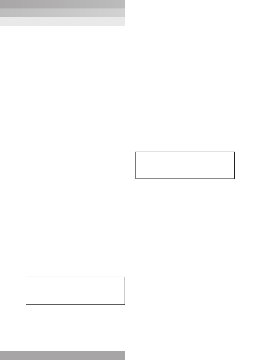
Electrical differential pressure switch operation:
When preset differential pressure is exceeded continuity
switches from ‘C’ - ‘A’ to ‘C’ - ‘B’.
When differential pressure decreases below the pre-set value
continuity returns to ‘C’ - ‘A’.
4A (resistive)
4A (resistive)
5A (resistive)
1.5A (resistive)
0.5A (resistive)
ENGLISH
Figure 1 - Switch Circuit Diagram
or white
or tag 1
B
or red
LOW DIFFERENTIAL PRESSURE
C
or black
or tag 2
7 Filter element servicing
During servicing the external surfaces of the filter assembly
must be cleaned to remove any dust deposits. Servicing
must be conducted using suitable tools that do not present
a hazard. Do not service when a potentially explosive
atmosphere is present.
CAUTION:
Filter elements should be replaced upon indication or
at specified intervals, six months maximum. Failure to
change the element will cause the filter to go into bypass.
Refer to Pall Product Literature for item numbers for applicable
replacement element series. Remove and replace element as
follows:
WARNING:
FAILURE TO DEPRESSURISE THE FILTER BEFORE
SERVICING ELEMENT COULD RESULT IN EXPLOSIVE
LOSS OF FLUID, DAMAGE TO EQUIPMENT AND
POSSIBLE PERSONAL INJURY.
3
Page 4
UR229
UR229 Series
DUPLEX FILTER ASSEMBLY service instructions
7.1 Open the bleed plug (5) on the off-line housing cover
a minimum of one and one half turns. Open commuter
valve (2) three full turns to equalize pressure between
the off-line housing and the on-line housing. Close the
commuter valve (2) when a bubble free stream of oil
flows from the bleed plug. Tighten the bleed plug.
7.2 Pull the latching pin and rotate change over valve handle
(7) 180° to bring off-line housing on-line. Insert latching
pin to prevent accidental handle movement.
NOTE: Pointed end of change-over valve handle (7) indicates
the filter housing on-line.
7.3 The off-line housing is now isolated from the system
by the changeover valve. Depressurize the housing by
slowly venting through the bleed plug (5). Remove drain
plug (8) on the filter head and drain fluid into a suitable
container. Discard fluid in accordance with local Health
and Safety regulations. Close drain plugs (5 and 8).
NOTE: During element replacement some small internal
leakage may be noted from the on-line filter housing. If a
large amount of leakage occurs, the ball valve seals may
require adjustment or the check valve seals need servicing.
Check for closure of commuter valve before disassembling
of unit for repairs.
7.4 Manually remove the cover (4) from tube (3). Remove
element (10) and carefully inspect the surface for
significant visible contamination. Normally no dirt should
show but visible dirt or particles can be an early warning
of system component breakdown and can indicate
potential system failure. Discard both the element
and its O-ring in accordance with local Health and
Safety Procedures. The filter element is
NOT CLEANABLE. Any attempt to clean the filter can
cause degradation of the filter medium and allow
contaminated fluid to pass through the filter.
7.5 Inspect filter cover (4) and tube (3) for possible damage
or malfunction and replace if damage is observed.
Remove any accumulated dirt from the filter tube and
cover interior, being careful to prevent contaminant
from entering the outlet and flowing downstream.
DO NOT run the system without a filter element (10)
installed. Inspect the O-rings on the cover (4) for
damage and replace if necessary. Use the correct
replacement filter element (10) part number called for
on assembly nameplate.
7.6 Lubricate element O-ring seal with clean system fluid
and push filter element (10) straight into filter housing.
Ensure that the O-ring end of the element points
towards the head. Ensure the cover (4) and tube (3)
threads are clean and dry. Lightly lubricate cover seal
with clean system fluid. HAND TIGHTEN cover or tube
and cover until it bottoms out.
7.7 Use a torque wrench and tighten cover and tube
assembly to 10-14 FT LBS (13-19 Nm).
Do Not Over Tighten.
WARNING:
FAILURE TO REPLACE DAMAGED PARTS IN THE
FILTER ASSEMBLY CAN CAUSE COMPONENTS IN
THE HYDRAULIC SYSTEM TO FAIL OR DEGRADE IN
THEIR PERFORMANCE.
7.8 Open the bleed plug (5) on the off-line housing cover
one and one half turns. Open commuter valve (2) three
full turns to equalize pressure between the offline
housing and the on-line housing. Close the commuter
valve when a bubble free stream of oil flows from the
bleed plug. Tighten the bleed plug.
7.9 After element change ENSURE VISUAL DIFFERENTIAL
PRESSURE WARNING DEVICE IS RESET BY
PUSHING IN THE BUTTON; electrical devices are
reset automatically. When system reaches normal
operating temperature, check that the electrical switch
has not actuated and/or that visual warning button
remains depressed. If visual indicator actuates due to
a cold start condition, reset indicator as per Section 6.
Filter housing is now ready for change-over when
required.
8 Ball Valve Servicing
Refer to Service Parts List (Section 11 and 12) for item
numbers for seal kits and Pall product literature for
replacement part.
8.1 Completely shut down system and depressurize system
by opening bleed plug (5). Remove drain plug (8) after
depressurizing.
WARNING:
FAILURE TO DEPRESSURISE THE SYSTEM BEFORE
SEVICING UNIT COULD RESULT IN EXPLOSIVE
LOSS OF FLUID. DAMAGE TO EQUIPMENT AND
POSSIBLE PERSONAL INJURY
8.2 With the ball valve handle shaft facing the operator and
the handle pointer pointing to the right side, remove the
right hand Head Assembly.
8.3 Remove in the following order:
(a) Remove Filter Element (10) per section 7.
(b) Remove 4 socket head cap screws (6), loosen 1 hex
head bolt (6.1) and remove the head assembly.
(c) Unscrew retainer seat (14) and O-ring (16) (see Fig. 5).
(d) Remove outer ball seat (17)
(e) Remove ball (19) (Note ball orientation when removing)
(f) Remove inner ball seat (17)
(g) Remove handle from valve shaft (7)
(h) Remove valve shaft (28)
8.4 Replace all O-rings, nylon bar in retainer, ball seats and
valve shaft washer (30). Use appropriate kit per type of
seal. See Ball Valve Seal Kit list.
NOTE: Lubricate all o-rings before installation.
8.5 Install in the following order;
(a) Valve shaft (28) and handle (7), ensure the pointer on the
valve handle points to the disassembled side.
(b) Inner ball seat (17) and O-ring (18).
(c) Orient the ball such that the groove aligns with the key
on the stem of the handle, install ball (19).
(d) Outer ball seat (17) and O-ring (18),
(e) Install Retainer Seat Valve (14), Tighten Retainer Seat
Valve into valve body so that ball cannot move, then
back Retainer off by 1/8 to 1/4 turn to allow for rotation
of ball. (Resistance to ball rotation must be present. Free
rotation is not acceptable).
4
Page 5

UR229
UR229 Series
DUPLEX FILTER ASSEMBLY service instructions
(f) Install O-rings (13, 20) into grooves in head.
(g) Clean all threads before applying Loctite 243 medium
strength to Socket Head Cap Screws (6) and hex bolt
(6.1), install and torque to 50-55 LB-FT.
(i) Install Filter Element (10) per Section 7.
8.6 Lubricate o-rings and install bleed and drain plugs (5
and 8) and torque to 10-14 LB-FT.
8.7 Commission filter assembly per Section 4.5.
9 Check Valve Servicing
NOTE: Service Check Valve at the same time
as Ball Valve service.
WARNING:
FAILURE TO DEPRESSURISE THE SYSTEM BEFORE
SERVICING UNIT COULD RESULT IN EXPLOSIVE
LOSS OF FLUID. DAMAGE TO EQUIPMENT AND
POSSIBLE PERSONAL INJURY.
9.1 Completely shut down system and depressurize system
by opening bleed plugs (5) and remove drain plugs (8)
after depresurizing.
9.2 With the ball valve handle shaft facing the operator,
remove the right hand Head Assembly.
(a) Remove Filter Element (10) per section 7.
(b) Remove 4 Socket Head Cap Screws (6) and loosen 1
hex head bolt. Remove head (1).
9.3 Remove Check Valve assembly by pulling straight
out. (11).
9.4 Restrain one of the valve seats and unscrew the
opposite end (see Fig. 8). (DO NOT DAMAGE SEAL
AREA AND DO NOT HOLD ONTO THE SHAFT).
9.5 Remove the poppets.
WARNING:
THIS ASSEMBLY IS SPRING LOADED. ENSURE
ASSEMBLY IS PROPERLY RESTRAINED DURING
DISASSEMBLY TO PREVENT POTENTIAL FOR
DAMAGE TO PARTS OR POSSIBLE PERSONAL INJURY.
9.10 Install head. Clean all threads before applting Loctite
243 medium strength to Socket Head Cap Screws (6)
and hex bolt (6.1), install and torque to 50-55 LB-FT.
9.11 Install Filter Element (10) per Section 7.
9.12 Lubricate o-rings and install bleed and drain plugs (5
and 8) and torque to 10-14 LB-FT.
9.13 Commission filter assembly per Section 4.7.
U-Cup Orientation
Figure 2
ENGLISH
NOTE: Lubricate all seals before installation. The open end of
the U-cup seal must point toward the center of the Check
Valve Assembly. (see Fig. 2)
9.6 Replace O-rings and U-cup seals. Use appropriate kit
per type of seal. See Check Valve Seal Kit list.
(Section 13)
NOTE: Poppets and seats are matched sets. Do not
interchange seats and poppets. See Fig. 3 for proper part
configuration.
9.7 Assemble (per Figure 3.)
NOTE: Use seal installation tool to install new seals and
poppets onto the valve shaft. Failure to use this tool will
damage the U-cup seals.
9.8 Clean all threads before applying removable Loctite 243
to shaft threads and attach removed seat.
9.9 Install Check Valve Assy. (11).
5
Check Valve Configuration
Figure 3
Page 6

UR229
UR229 Series
DUPLEX FILTER ASSEMBLY service instructions
10 Warranty, Limitation of Liability
and Remedies
THERE IS NO WARRANTY OF MERCHANTABILITY OR
FITNESS FOR ANY PARTICULAR PURPOSE WITH RESPECT
TO ANY OF THE PRODUCTS, NOR IS THERE ANY OTHER
WARRANTY EXPRESS OR IMPLIED, EXCEPT AS PROVIDED
FOR HEREIN.
For a period of twelve months from the date of delivery
from Seller or three thousand hours of use, whichever
occurs first (the “Warranty Period”), Seller warrants that
products manufactured by Seller when properly installed
and maintained, and operated at ratings, specifications and
design conditions, will be free from defects in material and
workmanship. By way of explanation and not limitation, the
Seller does not warrant the service life of the filter element
as this is beyond the Seller’s control and depends upon
the condition of the system into which the filter is installed.
Seller’s liability under any warranty is limited solely (in Seller’s
discretion) to replacing (FOB original ship point), repairing
or issuing credit for products that become defective during
the Warranty Period. Purchaser shall notify Seller promptly in
writing of any claims and provide Seller with an opportunity to
inspect and test the product claimed to be defective. Buyer
shall provide Seller with a copy of the original invoice for the
product, and prepay all freight charges to return any products
to Seller’s factory, or other facility designated by Seller. All
claims must be accompanied by full particulars, including
system operating conditions, if applicable. Seller shall not be
liable for any product altered outside of the Seller’s factory
except by Seller or Seller’s authorized distributor, and then,
as to the latter, only for products which have been assembled
by the distributor in accordance with Seller’s written
instructions. Nor shall Seller be liable for a product subjected
to misuse, abuse, improper installation, application, operation,
maintenance or repair, alteration, accident or negligence
in use, storage transportation, or handling. In no event will
Seller be liable for any damages, incidental, consequential
or otherwise, whether arising out of or in connection with the
manufacture, packaging, delivery, storage, use, misuse, or non
use of any of its products or any other cause whatsoever.Seller
shall not be liable for any product altered outside of the Seller’s
factory except by Seller or Seller’s authorized distributor,
and then, as to the latter, only for products which have been
assembled by the distributor in accordance with Seller’s written
instructions. Nor shall Seller be liable for a product subjected
to misuse, abuse, improper installation, application, operation,
maintenance or repair, alteration, accident or negligence
in use, storage transportation or handling. In no event will
Seller be liable for any damages, incidental, consequential
or otherwise, whether arising out of or in connection with the
manufacture, packaging, delivery, storage, use, misuse, or non
use of any of its products or any other cause whatsoever.
6
Page 7

UR229
UR229 Series
DUPLEX FILTER ASSEMBLY service instructions
11 Parts List
Fig. List Description Quantity
4 1 Head MC 2
2 Needle Commuter Valve 1
3 Tube 2
4 Cover MC Cap Service 2
5 Plug, Bleed Hex HD Cover 2
6 Screw, Cap, SOC HD 8
6a Bolt Hex HD 2
7 Handle MC 1
5 8 Plug, Bleed (Head) A14 2
9 Tube/Cover Assy. 2
6 10 Filter Element Assy.
11 Check Valve Assy. 1
12 Ball Valve Assy. 1
7 13 O-Ring -147 2
14 Retainer Seat, Ball Valve 1
15 Bar, Nylon .125 Dia x .141 Lg 1
16 O-Ring -033 1
17 Seat, Ball Valve 2
18 O-Ring -130 2
19 Ball, MC 1
20 O-Ring -134 2
8 21 O-Ring - 029 2
22 Seat, Valve 2
23 Poppet 2
24 Seal, U-Cup 2
25 Shaft, Valve 1
26 Spring, Compression 1
27 Installation Tool, U-Cup 1
UR219**+++ See product literature 2
ENGLISH
12 Filter Assembly Seal Kit List
Item Description Catalog Number Quantity
1 Nitrile 1386269 1
2 Fluorocarbon 1386270 1
3 Ethylene Propylene 1386271 1
13 Ball Valve Seal Kit
Item Description Catalog Number Quantity
1 Nitrile 1395024 1
2 Fluorocarbon 1395025 1
3 Ethylene Propylene 1395026 1
14 Check Valve Seal Kit
Item Description Catalog Number Quantity
1 Nitrile 1395027 1
2 Fluorocarbon 1395028 1
3 Ethylene Propylene 1395029 1
7
Page 8

UR229
UR229 Series
DUPLEX FILTER ASSEMBLY service instructions
Figure 4: UR229
5 Bleed Plug
4 Cover
3 Tube
6A Bolt
Hex
1 Head
7 Handle
8 Drain Plug
6 Socket Head Cap Screw
8
Page 9

UR229C/UR229H
UR229C/UR229H Series
DUPLEX FILTER ASSEMBLY service instructions
8 Drain Plug 8 Drain Plug
ENGLISH
9
Page 10

UR229C/UR229H
UR229C/UR229H Series
DUPLEX FILTER ASSEMBLY service instructions
Figure 6
10 Filter Element
11 Check Valve
12 Ball Valve
10
Page 11

UR229
UR229 Series
DUPLEX FILTER ASSEMBLY service instructions
Figure 7
28 Valve Shaft
29 O-Ring - 116
30 Teflon Washer
16 O-Ring - 033
14 Retainer
*15 - Exploded view of Nylon Bar locking nub
22 Valve Seat
24 U Cup Seal
25 Shaft
21 O-Ring - 029
18 O-Ring - 130
19 Ball
17 Ball Seat
*15 Nylon Locking Nub
26 Spring
24
13.1 O-Ring - 134
13 O-Ring - 147
23
22
21
ENGLISH
23 Poppet
11
27 U Cup
Installation Tool
Page 12

UR229
DUPLEX FILTER ASSEMBLY service instructions
UR229 Series
Pall Machinery and Equipment
25 Harbor Park Drive
Port Washington NY 11050
+1 516 484 3600 telephone
+1 800 289 7255 toll free US
Portsmouth - UK
+44 (0)23 9233 8000 telephone
+44 (0)23 9233 8811 fax
www.pall.com/contact
Visit us on the Web at www.pall.com
Pall Corporation has offices and plants throughout the world. For Pall representatives in your area, please go to
www.pall.com/contact
Because of technological developments related to the products, systems, and/or services described herein,
the data and procedures are subject to change without notice. Please consult your Pall representative or visit
www.pall.com to verify that this information remains valid.
© Copyright 2018, Pall Corporation. Pall and are trademarks of Pall Corporation.
® Indicates a trademark registered in the USA. Better Lives. Better Planet. and Filtration. Separation. Solution.SM
are service marks of Pall Corporation.
September 2018. Printed in the UK. M&ESIUR229ENa
 Loading...