

Page 1
UH319
UH319 Series
service instructions
UK60898 IMSIUH319c
EN
UH319 Service Instructions
ENGLISH
Page 2
UH319
UH319 Series
HIGH PRESSURE FILTERS service instructions
2
1 Specifications
Housing materials:
Head: Ductile cast iron
Tube and Cover: Carbon steel
Maximum operating pressure:
420 bar (6,100 psi)
Proof pressure:
750 bar (10,875 psi)
Typical burst pressure:
1,500 bar (21,750 psi)
Element burst pressure:
UE319 element 10 bard (150 psid) differential minimum
Operating temperature range:
-29°C to 120°C (-20°F to 250°F) with fluorocarbon seals for
petroleum based and specified synthetic fluids
60°C (140°F) maximum in HWCF, water-oil emulsion or
water glycol
Bypass valve setting options:
4.5 ± 0.3 bard (65 ± 5 psid) cracking pressure
Seals:
Fluorocarbon
The actual operating conditions should be checked by the user
to ensure that the element, housing and all seals are
compatible with the fluid and application, and are within local
safety codes. Please contact Pall or an approved distributor if
further information is required.
2 Receipt of equipment
The filter housing, and any optional equipment, are packed
individually for assembly by the customer. Unpack carefully
and ensure optional items are not mislaid in packaging to
be discarded.
3 General sources of information
3.1 For dimensions, operating parameters,
assembly/element part number, ordering information,
notes, performance data and specifications refer to
datasheet IMUH319EN.
3.2 This equipment has been assessed in accordance with
the guidelines laid down in the European Pressure
Directive 97/23/EC and has been classified within sound
engineering practice S.E.P. We hereby declare the
equipment meets the requirements of article 3, section
3, thus meeting the directive requirements. Under the
provisions of this directive the filter assembly is suitable
for use with group 2 fluids only.
3.3 Where under reasonably foreseeable conditions,
including external fires, the allowable limits could be
exceeded, suitable protective devices must be installed
by the customer within the connecting fluid system.
4 Installation of housing
4.1 The filter can be installed in any attitude, but for ease of
servicing, it is recommended that it be installed vertically
with the filter tube and cover pointing upwards
(UH319C) or with the filter tube and cover pointing
downwards (UH319H).
4.2 The minimum clearance required for element removal
is as follows:
4.2.1 UH319C series (cover service): 205mm (8.1in)
for length 8, 340mm (13.4in) for length 13,
510mm (20in) for length 20 and 1020mm
(40.2in) for length 40 housings.
4.2.2 UH319H series (head service): 138mm (5.5in)
for all lengths.
4.2.3 The UH319 Housing is supplied without a filter
element. For element installation and servicing
procedures, refer to Section 7.
4.3 Threaded differential pressure devices, when fitted, must
be torque tightened to 38 ft/lb or 54 Nm. All visual
indicators must be clearly visible.
NOTE: The UH319 head is supplied with two machined
differential pressure warning device ports, one fitted with a
bleed plug, the other with a plastic shipping plug. If no differential
pressure warning device is ordered, the shipping plug must
be removed and replaced with a 'B' type blanking plug
(P/N HA9000A104Z) and torque tightened to 40 ft/lb /54 Nm.
NOTE: Never place the port plug in this port without first
installing uniform size -014 O-ring in lower O-ring groove,
otherwise a small bypass flow will result, allowing contaminant
downstream of the filter element.
4.4 Mount the filter assembly in position using four
7/16-14 ('A' and 'E' ports) or M10 x 1.5 ('C' and 'G'
ports) bolts in the holes on the head mounting pads.
Torque bolts to 9-19 ft/lb or 12-26 Nm.
4.5 Use a check valve downstream of the filter if there is a
possibility of reverse flow.
4.6 Install the filter housing using additional piping/valving to
allow complete filter assembly bypass if filter maintenance
is required without system shutdown. This series is not
available in a duplex or service bypass configuration.
NOTE: Piping supports should be provided as close as is
practicable to the port connections in order to minimize
external loads. This filter assembly must not be electronically
isolated from the users earthing system. This filter assembly
must be earthed by connecting the users earthing system to
one of the inlet/outlet connections.
4.7 Connect lines or hoses to housing inlet and outlet ports.
CAUTION:
Maximum surge flow should not exceed 1.3 times
normal flow.
WARNING:
USE FITTINGS OR ADAPTORS COMPATIBLE WITH
PORTS SUPPLIED AS SHOWN BY PART NUMBER ON
NAMEPLATE AND NOTED IN DATA SHEETS: USE OF
INCORRECT FITTINGS OR ADAPTORS CAN CAUSE
FILTER HOUSING OR MANIFOLD FAILURE
RESULTING IN LOSS OF PRESSURE AND POSSIBLE
SYSTEM FAILURE OR PERSONAL INJURY.
CAUTION:
Reverse flow through filter element will cause damage.
CAUTION:
Never operate the filter unless both warning device
ports are sealed.
Page 3
UH319
UH319 Series
HIGH PRESSURE FILTERS service instructions
3
Note: Painting of the filter housing is optional. The coating on
the filter housing is a suitable painting base. Cover the
differential pressure warning device and nameplate if painting
of the housing takes place.
4.8 Bleed the filter
4.8.1 UH319C series (cover service): Bleed the filter by
opening the vent plug (7) at the top of filter one and one
half turns. Jog system and fill filter until all air bleeds
through the plug, then torque tighten the vent plug to
12 ft/lb or 16Nm.
4.8.2 UH319H series (head service): Bleed the filter by opening
the blanking plug (6b) one and one-half turns. Jog system
and fill filter until all air bleeds through the plug, then
torque tighten the blanking plug to 40 ft/lb or 54 Nm.
Pressurize system fully and check for leaks; if leaks occur
refer to section 5.
5 Routine maintenance
5.1 Pall filters do not normally require special attention
except for periodic monitoring of the differential pressure
warning device. Schedule replacement of filter element
every six months or sooner, and have ample supply of
spare elements available.
5.2 If external leakage is noted, replace O-ring at leak. If
leakage persists, check sealing surfaces for scratches or
cracks; replace any defective parts.
5.3 Differential pressure devices actuate when the element
needs changing or because of high fluid viscosity in
'cold start' conditions. If 'cold start' conditions exist, see
Section 6.2 and 6.3.
5.4 A dirty system can quickly plug a new filter element,
especially with Pall high efficiency filter media. It may
require one or two initial element changes to stabilize
element life. If element life is short or differential
pressure is excessive, filter may be undersized; refer to
the sizing and selection section of the product literature
or contact your local Pall representative.
5.5 Make sure element change labels are clean and
undamaged. Replace illegible labels with the appropriate
new labels.
6 Differential pressure devices
Reference should be made to product literature for dimensions,
operating parameters, part numbering, ordering information
and specifications.
6.1 Differential pressure devices actuate when the element
needs changing or because of high fluid viscosity in
'cold start' conditions.
6.2 If visual indicator is fitted and actuates during 'cold start'
(red button extends 5mm, 3/16"), reset by depressing the
button when the normal operating temperature is reached.
If indicator actuates after resetting, replace element.
NOTE: Option 'P' visual indicator has thermal lockout and manual
reset. No signal below 0°C (32°F), signal above 29°C (80°F).
6.3 If the electrical switch actuates (e.g. red light comes on)
during cold start, continue operating until the signal (red
light) goes out as system warms to normal operating
temperature. This feature can be used as 'warm up'
indication in operating procedures. If the warning signal
(red light) remains or appears when system is warm,
replace the filter element.
ENGLISH
6.4 Use of both positive indication (green light) and negative
indication (red light for dirty element) is recommended to
effectively monitor filter element life.
Electrical connections and ratings for all differential
pressure switch options:
110 VAC = 4A (inductive),
4A (resistive)
220 VAC = 4A (inductive),
4A (resistive)
28 VDC = 3A (inductive),
5A (resistive)
48 VDC = 1A (inductive),
1.5A (resistive)
125 VDC = 0.25A (inductive),
0.5A (resistive)
Maximum inrush - 24 amps.
Underwriter’s lab. Inc. listed ratings of pressure switch
(Microswitch) options are:
4 amps at 250 VAC
0.25 amp resistive at 220 VDC
0.50 amp resistive at 110 VDC
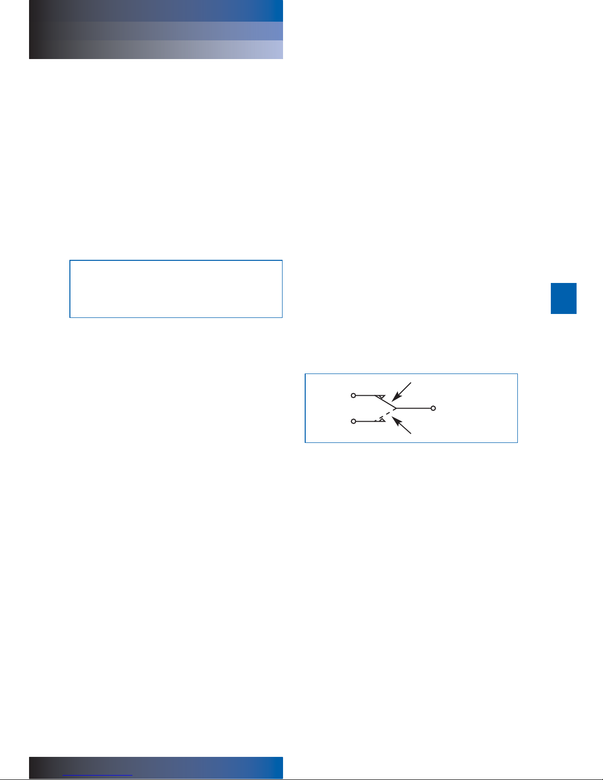
Electrical differential pressure switch operation:
When preset differential pressure is exceeded continuity
switches from 'C' - 'A' to 'C' - 'B'.
When differential pressure decreases below the pre-set value,
continuity returns to 'C' - 'A'.
Figure 1 - Switch Circuit Diagram
C
or black
or tag 2
CAUTION:
Failure to bleed the filter housing adequately will
increase the dissolved air content of the system fluid
which will shorten fluid life and may cause other
problems in the system.
A
or white
or tag 1
B
or red
or tag 3
LOW DIFFERENTIAL PRESSURE
HIGH DIFFERENTIAL PRESSURE
Page 4

UH319
UH319 Series
HIGH PRESSURE FILTERS service instructions
7.3 DO NOT run the system without a filter element
installed. For UH319C series: check that the O-ring (4)
between the cover (3) and tube (2) is not damaged. For
UH319H series: check that the O-ring (5) between the
tube (2) and head (1) is not damaged. Use the
replacement filter as indicated by the part number on
the element endcap.
7.4 Lubricate element O-ring with clean system fluid.
Reinstall element in the shell assembly. Lightly lubricate
cover-to-head or tube-to-head (as applicable) O-ring
with clean system fluid and reassemble the housing
until thread bottoms. The cover or tube should be
torque tightened using a suitable socket wrench
to 74 ft/lb or 100 Nm.
7.5 Bleed the system and check for leaks as per
section 4.8.
7.6 After element change ENSURE DIFFERENTIAL
PRESSURE DEVICE IS RESET BY PUSHING IN THE
RED BUTTON; electrical switches reset automatically.
When system reaches normal operating temperature,
check that the electrical switch has not actuated and/or
the visual warning button has remained depressed. If
visual indicator rises due to a cold start condition, reset
again as per section 6.
8 Warranty, Limitation of Liability and
Remedies
THERE IS NO WARRANTY OF MERCHANTABILITY OR
FITNESS FOR ANY PARTICULAR PURPOSE WITH RESPECT
TO ANY OF THE PRODUCTS, NOR IS THERE ANY OTHER
WARRANTY EXPRESS OR IMPLIED, EXCEPT AS PROVIDED
FOR HEREIN.
For a period of twelve months from the date of delivery from
Seller or three thousand hours of use, whichever occurs first
(the "Warranty Period"), Seller warrants that products
manufactured by Seller when properly installed and
maintained, and operated at ratings, specifications and design
conditions, will be free from defects in material and
workmanship. By way of explanation and not limitation, the
Seller does not warrant the service life of the filter element as
this is beyond the Seller's control and depends upon the
condition of the system into which the filter is installed.
4
7 Filter element installation / servicing
During servicing, the external surfaces of the filter assembly
must be cleaned to remove any dust deposits.
Servicing must be conducted using suitable tools that do not
present a hazard.
Servicing must not be carried out when a potentially explosive
atmosphere is present.
Refer to Service Parts List (Section 9) for item numbers for
applicable replacement element series. Remove and replace
element as follows:
7.1 Turn off and depressurize the system.
7.1.1 For UH319C series (cover service):
Open vent plug (7) at top of filter one and one-half turns.
Open the blanking plug (6b) partially on the filter head
and drain fluid into waste receptacle.
This sequence may be long for high viscosity fluids.
Replace ad torque tighten drain plug to 12 ft/lb or 16Nm.
Unscrew and remove cover (3) from tube (2) counter-
clockwise when viewed from above. It will be necessary
to use a 1" socket wrench on the hexagon on the cover
(3) to loosen the cover initially.
Note: The UH319C series assembly is equipped with Pall’s
'Auto-Pull' element extraction mechanism to facilitate element
removal. While removing the cap, tabs on the element endcap
lock into hooks in the cap and the element is automatically
pulled from the nipple.
7.1.2 For UH319H series (head service):
Open the drain plug (7) at the bottom of the bowl
assembly (tube and cover) and drain fluid from the bowl
into a suitable waste receptacle. Replace and torque
tighten drain plug to 12 ft/lb or 16Nm. Unscrew and
remove the bowl assembly (2 and 3) from head (1)
counter-clockwise when viewed from below. It will be
necessary to use a 1" socket wrench on the hexagon on
the cover (3) to loosen the cover initially.
7.2 Element replacement (UE319 Series): Remove filter
element (8), if already fitted, and carefully inspect the
interior surface (flow through the element is in-to-out) for
visible contamination. Normally no dirt should show, but
visible dirt or particles can be an early warning of
system component failure. Discard both the filter
element and its O-ring. The filter element is NOT
CLEANABLE. Any attempt to clean the filter element can
cause degradation of the filter medium and allow
contaminated fluid to pass through the filter element.
WARNING:
DO NOT ATTEMPT TO CLEAN OR RE-USE THE
ELEMENT. ONLY USE GENUINE PALL
REPLACEMENT FILTER ELEMENTS.
CAUTION:
Filter elements should be replaced upon indication or
at specified intervals, six months maximum. Failure to
change the element will cause the filter to go on
bypass.
Page 5

UH319
UH319 Series
HIGH PRESSURE FILTES service instructions
ENGLISH
Seller's liability under any warranty is limited solely (in Seller's
discretion) to replacing (FOB original ship point), repairing or
issuing credit for products that become defective during the
Warranty Period. Purchaser shall notify Seller promptly in
writing of any claims and provide Seller with an opportunity to
inspect and test the product claimed to be defective. Buyer
shall provide Seller with a copy of the original invoice for the
product, and prepay all freight charges to return any products
to Seller's factory, or other facility designated by Seller. All
claims must be accompanied by full particulars, including
system operating conditions, if applicable.
Seller shall not be liable for any product altered outside of the
Seller's factory except by Seller or Seller's authorized
distributor, and then, as to the latter, only for products which
have been assembled by the distributor in accordance with
Seller's written instructions. Nor shall Seller be liable for a
product subjected to misuse, abuse, improper installation,
application, operation, maintenance or repair, alteration,
accident or negligence in use, storage transportation or
handling.
In no event will Seller be liable for any damages, incidental,
consequential or otherwise, whether arising out of or in
connection with the manufacture, packaging, delivery, storage,
use, misuse, or non use of any of its products or any other
cause whatsoever.
5
9 Parts List
List Description Part Number Quantity
1 Head 1
2 Tube 1
3 Cover 1
4, 5 O-ring (cover-to-tube and head-to-tube) UH319SKZ 2
Seal Kit (fluorocarbon)
6, 6b Indicator and port plug kit (not shown) See product literature 2
7 Vent/drain plug 1
8 Filter element UE319**++Z
See product literature 1
Page 6

UH319
UH319 Series
service instructions
6
2
4
8
6b
3
1
Figure 2
5
7
6
Not shown
on this diagram
Not shown
on this diagram
Inlet
HIGH PRESSURE FILTERS
Page 7

UH319
UH319 Series
service instructions
7
Figure 3
Z
4 HOLES FULL THREAD DEPTH AA
4 Gewindebohrungen mit Gewindetiefe AA
4 huller med gevind, dybde AA
4 taladros pasantes roscados. Profundidad A
A
4 täyskierteistä reikää, syvyys AA
4 trous taraudés de profondeur AA
4 fori completamente filettati profondità AA
4 tapgaten (met draad over volle diepte)
4st fästhål. Gänga "Z". Min gängdjup "AA"
GG
Q
Flange Connection Details
Flange Code Nominal Tube Size GG Q Z Thread AA
E20 1
1
⁄4" 1.250" 2.625"
1
⁄2" - 13 UNC 0.75"
G20 1
1
⁄4" 31.8 mm 66.7 mm M12 x 1.75 19 mm
E24 1
1
⁄2" 1.437" 3.125"
5
⁄8" - 11 UNC 1.38"
G24 1
1
⁄2" 36.5 mm 79.4 mm M16 x 2.00 35 mm
E32 2" 1.750" 3.812"
3
⁄4" - 10 UNC 1.5"
G32 2" 44.5 mm 96.8 mm M20 x 2.50 38 mm
HIGH PRESSURE FILTERS
Page 8

UH319
UH319 Series
HIGH PRESSURE FILTERS service instructions
Because of developments in technology these data or procedures may be subject to change. Consequently
we advise users to review their continuing validity annually. Part numbers quoted above are protected by the
Copyright of Pall Europe Limited.
, Pall and Ultipleat are trademarks of Pall Corporation.
Filtration. Separation. Solution is a service mark of Pall Corporation.
® indicates a trademark registered in the USA.
© Copyright 2008, Pall Corporation.
October 2008. Printed in England. IMSIUH319c
Visit us on the web at www.pall.com
Pall Corporation has offices and plants throughout the world in locations including:
Argentina, Australia, Austria, Belgium, Brazil, Canada, China, France, Germany, India, Indonesia,
Ireland, Italy, Japan, Korea, Malaysia, Mexico, the Netherlands, New Zealand, Norway, Poland,
Puerto Rico, Russia, Singapore, South Africa, Spain, Sweden, Switzerland, Taiwan, Thailand,
United Arab Emirates, United Kingdom, United States, and Venezuela. Distributors are located
in all major industrial areas of the world.
Pall Industrial Manufacturing
New York - USA
+1 888 333 7255 toll free
+1 516 484 3600 telephone
+1 516 484 6247 fax
Portsmouth - UK
+44 (0)23 9230 3303 telephone
+44 (0)23 9230 2507 fax
 Loading...