

Page 1

Instructions For Use (IFU)
USD 2554c
Pall Stax™ Capsule Filters
216495 - Pall Europe Ltd GN12.5291.qxd:Layout 1 1/6/12 14:10 Page 1
Page 2

1. Introduction
The following procedures must be followed for the installation of the Pall Stax filter system.
The instructions contained in the product documentation must be read thoroughly as they
contain valuable information gained by extensive experience. It is very important that all
instructions are carefully followed and where appropriate they should be incorporated into the
end user’s standard operating procedures. If some of the procedures do not suit your
needs,
please consult Pall or your local distributor before finalizing your system.
Use of this product in a manner other than in accordance with Pall’s current recommendations
may lead to injury or loss. Pall cannot accept liability for such injury or loss.
2. Specifications
The maximum working pressures and temperatures are specified in Table 1. Operation outside
the specifications and with fluids incompatible with the materials of construction may cause
personal injury and result in damage to the equipment. Incompatible fluids are fluids which
chemically attack, soften, stress, attack or adversely affect the materials of construction.
Please refer to Pall for a list of incompatible fluids.
Table 1
Operating Conditions
Maximum Operating Pressure 3.5 bar at 25 °C 1.0 bar at 60 °C
Maximum Operating Temperature 25 °C at 3.5 bar 60 °C at 1.0 bar
Recommended Operating Conditions Maximum differential Pressure 2.4 bar at 3.5 bar operating pressure
Contact Pall for advice in case of prolonged exposure at extremes of operating temperatures.
Warning: European Directive 94/9/EC (ATEX) Equipment Intended for Use in Potentially
Explosive Atmospheres For information relating to European Directive 94/9/EC (ATEX),
please refer to page 7. For information relating to Zone 0/20 Applications, please
contact Pall. Mo
re information can be obtained through Pall, your local distributor or the
Pall website.
3. Receipt of Equipment
Caution: Stax standard capsule and manifold assemblies are suitable for sterilization by
autoclaving. Stax carbon capsules incorporating Seitz®AKS media must not be
autoclaved. Please check the product label prior to use to ensure product part numbers
correspond to the application. Stax capsules and manifolds are supplied non-sterilized,
if unsure of suitable sterilization method, please contact Pall.
1. Store the capsules and manifold assemblies in clean, dry conditions between 0 °C and
30 °C without exposure to irradiation sources such as direct sunlight, and wherever
practical in the packaging as delivered.
2. Do not remove from packaging until just before installation.
3. Check that the bag or packaging is undamaged prior to use.
4. Ensure that the type of capsule assembly selected is suitable for the application.
5. In addition to the part number, each capsule assembly is identified by a unique identification
batch number and a unique serial number.
6. Stax capsule modules should be used within 36 months after their production date as
shown on the box label with the exception of Stax capsules with Bio-Series media, which
must be used within 18 months after their production date.
7. The manifold kits are equipped with protective caps on the inlet and oulet connections.
Please ensure these caps are removed prior to putting your system into operation.
2
USD 2554c
!
!
216495 - Pall Europe Ltd GN12.5291.qxd:Layout 1 1/6/12 14:10 Page 2
Page 3
4. Installation and Operation
Before installation, it is essential to verify that the capsule assembly type selected is suitable for
the product to be filtered and to follow the appropriate instructions listed below and the
diagrams in:
Appendix A: Chassis User Instructions — Pilot Scale on page 8
Appendix B: Chassis User Instructions — Process Scale 5 and 10 High on page 10
Appendix C: Chassis User Instructions — Series Filtration on page 12.
4.1 Installation
The Stax caps
ule system must only be used in conjunction with the appropriate supporting
chassis. Ensure that the required manifolds and capsules are installed in the correct
orientation for flow and that the inlet and outlet ports are adequately supported.
The distribution manifolds have the flow direction indicated on the pipes.
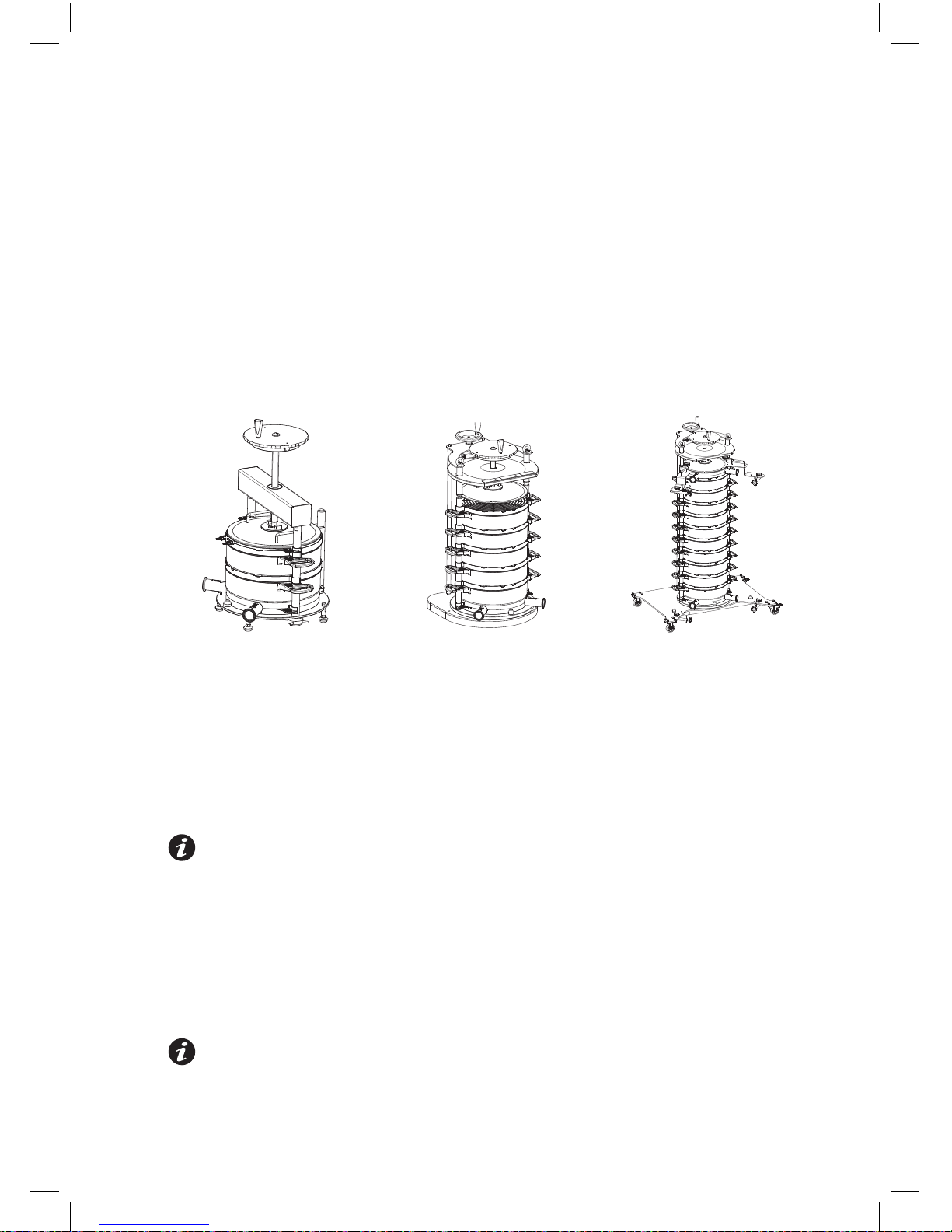
Figure 1
Typical Chassis Configurations (Drawings not to scale)
Pilot Unit 5-High Process Unit 10-High Process Unit
1. Ensure that the support chassis i
s located in a stable and level position. The process
scale chassis must be bolted securely to the floor or when fitted with wheels these must
be fully locked.
2. The Stax capsule assemblies must be stacked in a vertical orientation. Assembly of the Stax
capsule system begins with the correct placement of a distribution manifold on to the base
of the chassis. Capsules are then stacked on top in the correct orientation, ensuring that
the sealing gasket is correctly positioned flat between each item within each capsule and
distribution manifold retaining lugs, and then topped with the appropriate manifold.
For systems requiring flow in and out via the bottom distribution manifold, a vent
manifold must be fitted to the top of the stack. For bottom in and top out flow,
the stack must be topped with a distribution manifold. Refer to the Applications Note
for recommendations on when to use the alternative flow modes. Fluid flow must be
in the direction indicated on the distribution manifold and must be maintained within
the specifications.
3. The Stax capsule assembly may also be operated in series filtration mode in the same
process scale chassis with two sets of capsules containing different filter sheet grades.
Refer to Appendix C: Chassis User Instructions — Series Filtration on page 12 for correct
assembly. Both capsule sets should be completed with a vent manifold.
In series mode, the 10-high chassis is limited to 9 large capsules and in the 5-high
chassis to 4 large capsules.
3
USD 2554c www.pall.com/biopharm
216495 - Pall Europe Ltd GN12.5291.qxd:Layout 1 1/6/12 14:10 Page 3
Page 4

4. Ensure that the capsule stack is correctly clamped by the chassis clamping plate before
connecting the hoses. No gaps should exist between the capsules, manifold and the
clamping plate.
5. Control valves should be fitted to the inlet and outlet pipes of the distribution manifolds to
control fluid flow. Venting of the system must be carried out before operation through the
valves on the vent manifold. When used with fluid flow in through the bottom of the system
and out through the top, venting can be achieved through the control valve fitted to the inlet
of the top manifold and through the outlet pipe.
6. To assist with post-use blown down, it is recommended that for bottom-in, top-out flow
configuration, that the bottom outlet valve should be shut during normal operation and opened
for draining down after use. Refer to section 7.1 for post-use drainage and blow down.
7. Where a positive pressure exists downstream of the capsule assembly, a sensitive check
valve may be needed to prevent back pressure damage due to reverse flow.
8. Where pulsating flow is present, the capsule assembly should be protected by a surge tank
or similar device upstream.
9. Where a rapidly closing downstream valve is present, the possibility of pressure pulsing and
subsequent filter damage exists. The capsule assembly should be protected by a surge
tank or similar device between valve and filter.
10. Depending on the application, rinsing with filtered water or buffer in a forward flow
direction is recommended prior to putting the Stax capsules into operation. Rinsing can be
performed with product or a product-compatible liquid. The recommended rinsing volume
is 50 L/m2of filter area for single layer filters and 100 L/m2of filter area for double layer
filters. The recommended flow rate for the rinsing cycle is 1.5 times the process flow rate.
4.2 Operation
Warning: Do not remove or attempt to remove the blanking caps, vent and drain
valves while the capsule assembly is in use. All valves or blanking caps must be
closed during filtration once venting operations have been performed. Stax
capsules and manifolds must not be used without the appropriate chassis.
4.2.1 Liquid Applications
1. Stax standard capsules are suitable for autoclaving and the system can be
operated under sterile conditions. However, Stax capsule filter media are not
sterilizing grade filters and will
not sterilize a non-sterile liquid.
Warning: Stax carbon capsules incorporating Seitz AKS media must not
be autoclaved.
2. Remove the capsule and manifolds from their bags or protective autoclave
wrapping and correctly assemble into the chassis as described in Appendix A:
Chassis User Instructions — Pilot Scale on page 8 or Appendix B: Chassis User
Instructions — Process Scale 5 and 10 High on page 10. Attach process lines to
the appropriate inlet and outlet pipes of the manifold using sanitary flange
connections, ensuring that the gaskets are properly installed and the clamps
adequately tightened.
3. The valves are operated by rotation; rotate counter clockwise to open, rotate
clockwise to close. Where fitted open the vent valves and slowly begin to fill the
capsule. Close the vent valves as soon as all excess air escapes the assembly
and liquid reaches the level of the vents.
4. Gradually increase the flow rate or pressure to the desired value. Do not exceed
the maximum operating parameters listed in the specifications section of the
product datasheet.
4
USD 2554c
!
!
216495 - Pall Europe Ltd GN12.5291.qxd:Layout 1 1/6/12 14:10 Page 4
Page 5

5. When filtration is complete, residual fluid within the capsules can be displaced by
an air purge to minimize hold-up of solution in the assembly.
6. The chassis should be cleaned after use and all moving parts checked for signs of
wear. Worn parts must be replaced. Replacement parts can be ordered through
Pall or your local distributor.
4.2.2 Gas Applications
The Stax Capsule system is not intended for gas applications. However, an air pressure hold installation test ma
y be conducted at < 0.35 bar (5 psi) to confirm system
assembly integrity before use.
5. Sterilization, Sanitization and Decontamination
Caution: Stax filter capsules and manifolds are not intended to be reusable. Discard
capsules and manifolds in accordance with local Health and Safety and Environmental
procedures.
Warning: Stax filter capsules and manifolds must not be in-line steam sterilized. Material
design limitations will be exceeded when these filters are exposed to pressurized steam
and the housing may rupture.
5.1 Autoclaving (standard capsules only)
Caution: Please refer to the appropriate Pall product information literature for products
which can be autoclaved and the maximum recommended cumulative autoclave
exposure time.
Autoclave sterilization procedures for standard Stax capsules are detailed in Pall publication
USTR 805.
All materials can be autoclaved dry or wet post blow down.
Warning: Stax carbon capsules incorporating Seitz AKS media must not be autoclaved.
Do not autoclave the capsules in the bag supplied.
When sanitary connections are used, it is recommended that the sanitary clamp is not fully
tightened prior to autoclaving. The clamp should be fully tightened only when autoclaving
is completed.
The vent and drain valves should be fully opened before autoclaving.
Warning: Stax filter capsules and manifolds must not be gamma irradiated. Gamma
irradiation can result in degradation of the materials of construction resulting in potential
rupture of the capsules during use and may lead to personal injury.
The efficiency of the sterilization cycle is the responsibility of the user.
5.2 Hot Water Sanitization
The product can be sanitized either pre or post use with hot water up to 80 °C with a
maximum operating pressure of 1 bar g (14.5 psi g) and no more than 60 minutes total
exposure time at that temperature.
Caution: Hot water at 80 °C can lead to serious skin damage, so adequate care must
be taken to avoid uncontrolled spillage of hot water during the sanitization process.
Caution: Special care is needed upon system venting.
Caution: Before opening the system for disassembly you must ensure the Stax system
is no longer under pressure.
Caution: Hoses and tubings must be specified for use at 80 °C under pressure.
5
USD 2554c www.pall.com/biopharm
!
!!!
!
!
!
!
!
216495 - Pall Europe Ltd GN12.5291.qxd:Layout 1 1/6/12 14:10 Page 5
Page 6

Caution: Connections to drains must be secured to ensure controlled flow into the
plant drainage. Failure to do so may lead to serious health issues.
5.3 Sodium Hydroxide (NaOH) Decontamination
The product may be decontaminated once, post use, using an aqueous solution of up to
1M concentration of Sodium Hydroxide by either recirculation through the system at up to
250 liters/m2/hour or by filling the Stax system (static soak). Either method should not
exceed a 60 minute exposure time and a maximum solution temperature of 25 °C.
Warning: Stax capsules should not be exposed to 1M Sodium Hydroxide prior to use.
Caution: When decontaminating Stax systems with caustic solutions, appropriate
protective clothing including safety glasses must be worn.
Caution: Please liase with your local health and safety authorization on any plant specific
safety policies when handling these fluids.
Caution: Special care is needed upon system venting to avoid uncontrolled spillage.
Caution: Before disassemby of the modules, the system must be flushed with an
adequate amount of clean water to allow safe disposal.
Caution: Never attempt to open the system or associating tubings during caustic
exposure.
Caution: Hoses and tubings must be specified for use with 1 M NaOH.
Caution: Please liase with your plant safety authorization whether the required amount of
caustic solution can be handled by the plant sewage system directly or whether a
neutralization is needed prior to entering into the plant drainage system.
Caution: Any connections to drains or neutralization tanks must be secured to avoid
uncontrolled spillage. Failure to do so may lead to serious health issues.
6. Integrity Testing
The depth filter media incorporated into Stax filter capsules are not integrity testable to confirm
efficiency rating. Stax filter capsules are not supplied with sterilizing or virus grade membrane
that would be subject to integrity testing correlated to microbial efficiency. Stax filter capsules
can be installation tested by a low pressure hold test. Contact Pall for details.
7. Filter Assembly Replacement
Capsule assemblies and manifolds should be replaced in line with the GMP requirements of
the process. Where capsule assemblies are used for more than one manufacturing batch,
replacements are recommended when either the maximum allowable differential pressure has
been reached or the flow rate has become unacceptable whichever occurs first. Discard
capsule assembly in accordance with local Health and Safety and Environmental procedures.
No attempt should be made to clean disposable capsule assemblies and manifolds.
7.1 Post-Use Drainage and Blow Down
The blow down pressures are applicable to the filter media that has been wetted with water
only. After filtration with the product, add the value of the pressure differential o
f the Stax
system at the end of the process run to the pressures shown in Table 2: Blow Down
Pressures on page 7 and apply air pressure in incremental steps.
1. For units fitted with the vent manifold connect the air supply to the left hand vent valve.
Close the fluid inlet valve. Open the left hand vent valve fully and apply air pressure.
6
USD 2554c
!!!
!!!
!
!
!
!
216495 - Pall Europe Ltd GN12.5291.qxd:Layout 1 1/6/12 14:10 Page 6
Page 7

2. For units with a bottom in, top out flow configuration connect the air supply to the inlet
pipe on the top manifold. Close the outlet valve on the top manifold and the inlet valve to
the bottom manifold. Open the valve on the bottom outlet pipe and apply air pressure.
3. The blow down pressures are applicable to the filter media that has been wetted with
water only. After filtration with the product, please apply air pressure in incremental steps
to the pressures shown in Table 2: Blow Down Pressures on page 7.
Table 2
Blow Down Pressures
Media Type Air Pressure Time
EKSP (or BIO 10) and all 1000 mbar (14.5 psi) 10 minutes
multi-layer capsules with EKSP
as the bottom layer
EKMP, Supra EK1P (or BIO 20) 700 mbar (10.1 psi) 10 minutes
and all multi-layer capsules with
EKMP as the bottom layer
KS50P up to K200P or HP 400 mbar (5.8 psi) 10 minutes
combination capsules with these
sheets as the bottom layer
K250P up to K900P or HP 50 mbar (0.7 psi) 10 minutes
combination capsules with these
sheets as the bottom layer
All AKS carbon grades 250 mbar (3.6 psi) 10 minutes
8. Scientific and Laboratory Services
Pall operates a technical service to assist in the application of all filter products. This service is
readily available to you and we welcome your questions so that we can help. In addition, a full
network of technical representatives is available throughout the world.
Use of Pall Encapsulated Filter Assemblies per EC Directive 94/9/EC Equipment and Protective
Systems Intended for
Use in Explosive Atmospheres (ATEX).
Installation and maintenance should be undertaken by a competent person. National and local
codes of practice, environmental regulations and Health and Safety directives must be adhered
to and take precedence over any stated or implied practices within this document.
For fluids having low conductivity, there exist the possibility of the generation of static electricity
during use with polymeric components. This could potentia
lly lead to a static electricity
discharge resulting in the ignition of a potentially explosive atmosphere where such an
atmosphere is present. These Pall products are not suitable for use with such low conductivity
fluids in an environment that includes flammable liquids or a potentially explosive atmosphere.
Where flammable or reactive fluids are being processed through a Pall capsule assembly, the
user should ensure that spillages during filling, venting, depres
surizing, draining and capsule
change operations are minimized, contained or directed to a safe area. In particular, the user
should ensure that flammable fluids are not exposed to surfaces at a temperature that may
ignite the fluid, and that reactive fluids cannot contact incompatible materials that may lead to
reactions generating heat, flame or that are otherwise undesirable.
Pall capsule assemblies do not generate heat, but during the processing of high temperatu
re
fluids, and process upset conditions, the capsules will take on the temperature of the fluid
being processed. The user should ensure that this temperature is acceptable for the area in
which the filter is to be operated, or that suitable protective measures are employed.
7
USD 2554c www.pall.com/biopharm
216495 - Pall Europe Ltd GN12.5291.qxd:Layout 1 1/6/12 14:10 Page 7
Page 8

When processing flammable fluids, the user should ensure that any air is fully purged from
within the assembly during filling and subsequent operation to prevent the formation of a
potentially flammable or explosive vapor/air mixture inside the equipment. This can be achieved
through careful venting of the assembly or system as detailed in the user instructions.
To prevent damage or degradation which may result in leakage of fluids from this equipment it
is imperative t
hat the end user check the suitability of all materials of construction (including
seals on the connections where appropriate) with the process fluid and conditions. The user
should ensure that the assembly is regularly inspected for damage and leaks, which should be
promptly corrected, and that seals (where appropriate) are renewed after every capsule
change.
Leakage of flammable or reactive fluids from this assembly, arising through incorrect installation
or dama
ge to the equipment (including any seals), may generate a source of ignition if
flammable fluids are exposed to a heated surface, or if reactive fluids contact incompatible
materials that may lead to reactions generating heat, flame or that are otherwise undesirable.
The user should ensure that the assembly is regularly inspected for damage and leaks, which
should be promptly corrected, and that any seals are renewed after every filter change. The
user should ensure that
these products are protected from foreseeable mechanical damage
that might cause such leakage, including impact and abrasion. Should you have any questions,
please contact your local Pall office or distributor.
Appendix A: Chassis User Instructions — Pilot Scale
1. Pilot Scale Chassis Components Front View
Item Description Quantity
1 Torque Wheel and Limiter 1
2 Clamping Spindle 1
3 Cross Beam 1
4 Support Leg 2
5 Capstan Nuts 2
6 Clamping Plate 1
7 Rear Location Post 1
8 Cap Screw 1
9 Base Plate 1
2. Pilot Scale Chassis Assembly
To mount support legs:
1. Insert support legs through holes in base plate.
2. Attach capstan nuts to screw threads at end of
support legs.
3. Tighten capstan nuts by hand counterclockwise to
secure support legs to base plate.
4. Insert location post through the appropriate hole in
base plate.
5. Insert cap screw up into threaded hole in location post.
6. Tighten cap screw counterclockwise with appropriate
sized Allen Key.
8
USD 255
4c
1
2
3
4
5
6
7
8
9
216495 - Pall Europe Ltd GN12.5291.qxd:Layout 1 1/6/12 14:10 Page 8
Page 9

3. Fitment of Bottom Manifold
1. Position the manifold on base plate with the near tab
below the cross pin and the side tabs against the
support legs.
2. Push the manifold down flat onto the base plate.
3. Ensure that the gasket is flat within the retaining pegs of
the manifold.
4. Placement of First Filter Capsule
1. Center the capsule slightly above the manifold with the
side tabs latched around the support legs. Push the
capsule down to seat it on the bottom manifold.
2 Check the position of the gasket. It must lie flat fully
within the capsule recess.
5. Placement of Additional Filter Capsules
1. Place second capsule into position slightly above the
first capsule. Securely latch the side tabs around the
support legs.
2. Push the capsule down flat.
3. Check the position of the gasket. It must lie flat fully
within the recess.
6. Assembly of Changing Plate
1. Position the manifold on the top capsule.
2. Place clamping plate on top of the vent manifold with
rear support positioned between guide pins.
9
USD 2554c www.pall.com/biopharm
3. Unscrew fully the wing bolts and wind spindle down
through hole in retaining plate.
4. Slide retaining plate into spindle groove.
5. Align clamping plate with the two screw holes and
apply wing bolts and tighten securely.
7. Bottom In/Bottom Out Flow Version
1. Rotate torque wheel to clamp down capsules until
torque limiter clicks out and wheel rotates freely.
Check to ensure that capsules are fully clamped down.
2. Connect inlet and outlet hoses on the manifold
as indicated.
3. Open vent valves
4. Begin filling capsule until fluid appears.
5. Close valves.
6. Check for leaks.
216495 - Pall Europe Ltd GN12.5291.qxd:Layout 1 1/6/12 14:10 Page 9
Page 10

Appendix B: Chassis User Instructions — Process Scale 5 and 10 High
Stax Process Scale Chassis User Instructions
1. Process Chassis Sizes
The Stax process scale chassis is available in two sizes: 5-high and 10-high with two base
styles, floor or wheel mounted.
Figure 2
10
USD 2554c
Typical Chassis Configurations (Drawings not to scale)
2. Process Chassis Operation
1. With the clamping lever in the unlocked position, the
clamping head can be moved up and down to suit the
number of capsules required in the stack by rotating the
top handle.
2. When the clamping head is in the required poisition, it
must be locked in place by moving the clamping lever
to the locked position.
3. Process Chassis Operation Clamping Head
Lock Position
1. Move the clamping lever t
o the unlocked position.
The clamping plate moves forward.
2. Rotate the top handle to move the clamping head to
the required height. Align the clamping head with the
thin grooves in the support legs.
3. Move the clamping lever to the locked position.
The clamping head moves backwards.
4. Check to ensure that the clamping head is locked.
216495 - Pall Europe Ltd GN12.5291.qxd:Layout 1 1/6/12 14:10 Page 10
Page 11

4. Fitment of Bottom Manifold
1. Position the manifold on the base plate with the rear tab
below the cross pin and the side tabs against the
support legs.
2. Push the manifold down flat onto the base plate.
11
USD 2554c www.pall.com/biopharm
5. Placement of the First Filter Capsule
1. Center the capsule above the manifold with side tabs
latched around the support legs.
2. Push the capsule down firmly onto the manifold.
3. Check the position of the gasket. It must lie flat fully
within the recess in preparation for the next capsule.
6. Placement of Additional Filter Capsules.
1. Place the capsule into position slightly above the
previous capsule ensuring side tabs latch around
support legs.
2. Push the capsule down on top of the filter capsule
below.
3. Check the position of the gasket. It must lie flat fully
within the recess.
4. Repeat steps 1 to 3 for required number of capsules:
for the 5-high chassis, a maximum of 5 large capsules,
and for the 10-high chassis, a maximum of 10 large
capsules.
7. Bottom In/Bottom Out Flow Version
1. Clip the vent manifold onto the support bars and push
down onto top capsule.
2. Rotate torque wheel clockwise to clamp down capsules
until torque limiter clicks out and wheel rotates freely.
Check to ensure that capsules are fully clamped down.
3. Connect inlet and outlet lines to the bottom manifold as
indicated by the flow arrows on the manifold.
4. Open vent valves by rotating them counterclockwise.
5. Begin slowly filling capsules until fluid appears from
the valves.
6. Close vent valves by rotating them clockwise.
7. Check for leaks.
216495 - Pall Europe Ltd GN12.5291.qxd:Layout 1 1/6/12 14:10 Page 11
Page 12

8. Bottom In/Top Out Flow Version
1. Position top manifold with gasket facing down
onto capsule.
2. Attach hose support bracket securely to clamping plate.
3. Rotate torque wheel clockwise to clamp down capsules
until torque limiter clicks out and wheel rotates freely.
4. Connect inlet line to bottom manifold.
5. Connect outlet line to top manifold.
6. Cover open manifold ports with appropriate control
valves. A control valve should be fitted to the top inlet
pipe to assist with purging air and post use blow down.
12
USD 2554c
Follow the instructions for the Pilot Scale Chassis in Appendix
A: Chassis User Instructions — Pilot Scale on page 8, except:
1. Place a vent manifold on top of the first media grade capsule(s).
2 Place a distribution manifold on top of the first vent manifold.
3. Place the capsules of the second media grade on top of
the second distribution manifold.
4. Place a vent manifold on top of the second media
grade capsule(s).
5. Clamp capsules and manifolds using the torque wheel.
6. Co
nnect inlet and outlet lines to the distribution manifolds as
indicated by the direction of flow arrows on the manifolds.
7. Open vent valves and commence filling.
8. Close vent valves when fluid appears and check for leaks.
Appendix C: Chassis User Instructions — Series Filtration
Pilot Scale Chassis with Series Filtration Setup
For Series Flow filtration using two different media grades, the chassis will accommodate
combinations of large, medium and small capsules. Please contact your local Pall office or
distributor for guidance on combinations of capsule sizes.
Process Scale Chassis with Series Filtration Setup
For Series Flow using capsules of two different media grades, the chas
sis will accommodate
up to 9 large capsules in the 10-high chassis and up to 4 large capsules in the 5-high chassis.
Follow the instructions for the Process Scale Chassis in Appendix B: Chassis User Instructions
— on page 10, except:
1. Place a vent manifold on top of the first media grade capsule set
2. Place a distribution manifold on top of the first vent manifold
3. Place the capsule of the second media grade set on top of
the second distribution manifold
4. Place a vent manifold on top of the second media capsule set.
5. Clamp capsules and manifolds using the torque wheel.
6. Connect inlet and outlet lines to the distribution manifolds
as indicated by the direction of the flow arrows on the
manifolds.
7. Open vent valves and commence filling.
8. Close vent valves when fluid appears and check for leaks.
216495 - Pall Europe Ltd GN12.5291.qxd:Layout 1 1/6/12 14:10 Page 12
Page 13

13
USD 2554c www.pall.com/biopharm
Appendix D: Maintenance and Spare Parts
1. Maintenance
There is no specific need for maintenance other than routine cleaning, as described under
‘Care’ below. The critical part of the chassis is the spindle surface. The spindle itself can
provide approximately 50,000 N of force. The torque limiter is designed to limit the applied
force to a maximum of approximately 7,500 N. If the spindle accumulates soiling and build-up
over time, the amount of force delivered to the filter capsule stack can decrease. This decrease
in force may fall below the approximate 2,500 N minimum that ensures a full seal. The spindle
is constructed such that it locks itself thereby keeping the force on the capsule stack.
Note that force alone does not guarantee a seal. O-rings, filter capsules, etc. must be properly
installed. This is much the same as when a clamp and gasket connection requires proper
installation of the gasket into
the fitting and not simply closure of the clamp and tightening.
The recommended flush with DI or WFI water (50 L/m
2
for single layer depth filters, 100 L/m
2
for double layer) prior to depth filter use also serves as a system leak check. Any incidental or
improper capsule installation or chassis fitment will be viewed during a water flush as improper
fitment is fully expected to be a visible, macroscopic event.
The frequency of cleaning the spindle will strongly depend on envir
onmental conditions and
specific application usage. However, a yearly preventative maintenance is expected to be
sufficient in most cases.
2. Care
Routine cleaning of the external surfaces of the chassis to prevent bioburden and other residue
built-up can be followed on the same schedule as other external non-product contact parts,
such as manufacturing suite walls, control boxes and tank exteriors.
216495 - Pall Europe Ltd GN12.5291.qxd:Layout 1 1/6/12 14:10 Page 13
Page 14

Notes
Page 15

Notes
Page 16

3. Spare part list
Pilot Scale Chassis
a) SXLSC02LIMITER (1x spindle with Torque Limiter hand wheel as one unit)
b) SXLSC02FOOT (Suitable for Pilot Scale plinth version only)
c) SXLSC02CASTOR (Suitable for Pilot Scale chassis with castors)
Process Scale Chassis
a) SXPSCXXXLIMITER (1x spindle with Torque Limiter hand wheel supplied as one unit
suitable for 5 high and 10 high Process Scale Chassis , plinth or wheeled version)
b) SXPSCXXWCASTOR (1 x swivel castor assembly)
216495 - Pall Europe Ltd GN12.5291.qxd:Layout 1 1/6/12 14:10 Page 14
European Headquarters
F
ribo urg, S witz erland
+41 (0)26 350 53 00 phone
LifeSciences.EU@pall.com e-mail
Corporate Headquarters
P
ort Wash ington, N Y USA
+1.800.717.7255 toll free (USA)
+1.516.484.5400 phone
biopharm@pall.com E-mail
International Offices
Pall Corporation has offices and plants throughout the world in locations such as:
Argentina, Australia, Austria, Belgium, Brazil, Canada, China, France, Germany, India,
Indonesia, Ireland, Italy, Japan, Korea, Malaysia, Mexico, the Netherlands, New Zealand,
Norway, Poland, Puerto Rico, Russia, Singapore, South Africa, Spain, Sweden, Switzerland,
Taiwan, Thailand, the United Kingdom, the United States, and Venezuela. Distributors in all
major industrial areas of the world.
The information provided in this literature was reviewed for accuracy at the time of
publication. Product data may be subject to change without notice. For current information
consult your local Pall distributor or contact Pall directly.
© 2012, Pall Corporation. Pall, , Seitz and Stax are trademarks of Pall Corporation.
® indicates a trademark registered in the USA and TM indicates a common law trademark.
Filtration. Separation. Solution.SM and UpScale are services mark of Pall Corporation.
05/13, PDF, GN12.5291 USD 2554c
Visit us on the Web at www.pall.com/biopharm
E-mail us at stax@pall.com
3. Spare part list
Pilot Scale Chassis
a) SXLSC02LIMITER (1x spindle with Torque Limiter hand wheel as one unit)
b) SXLSC02FOOT (Suitable for Pilot Scale plinth version only)
c) SXLSC02CASTOR (Suitable for Pilot Scale chassis with castors)
Process Scale Chassis
a) SXPSCXXXLIMITER (1x spindle with Torque Limiter hand wheel supplied as one unit
suitable for 5 high and 10 high Process Scale Chassis , plin
th or wheeled version)
b) SXPSCXXWCASTOR (1 x swivel castor assembly)
Asia-Pacific Headquarters
S
ingapore
+65 6389 6500 phone
sgcustomerservice@pall.com e-mail
216495 - Pall Europe Ltd GN12.5291.qxd:Layout 1 1/6/12 14:10 Page 14
European Headquarters
Fr
ibourg, S witz erlan d
+41 (0)26 350 53 00 phone
LifeSciences.EU@pall.com e-mail
Corporate Headquarters
P
ort Wash ington, N Y USA
+1.800.717.7255 toll free (USA)
+1.516.484.5400 phone
biopharm@pall.com E-mail
International Offices
Pall Corporation has offices and plants throughout the world in locations such as:
Argentina, Australia, Austria, Belgium, Brazil, Canada, China, France, Germany, India,
Indonesia, Ireland, Italy, Japan, Korea, Malaysia, Mexico, the Netherlands, New Zealand,
Norway, Poland, Puerto Rico, Russia, Singapore, South Africa, Spain, Sweden, Switzerland,
Taiwan, Thailand, the United Kingdom, the United States, and Venezuela. Distributors in all
major industrial areas of the world.
The information provided in this literature was reviewed for accuracy at the time of
publication. Product data may be subject to change without notice. For current information
consult your local Pall distributor or contact Pall directly.
© 2012, Pall Corporation. Pall, , Seitz and Stax are trademarks of Pall Corporation.
® indicates a trademark registered in the USA and TM indicates a common law trademark.
Filtration. Separation. Solution.SM and UpScale are services mark of Pall Corporation.
05/13, PDF, GN12.5291 USD 2554c
Visit us on the Web at www.pall.com/biopharm
E-mail us at stax@pall.com
3. Spare part list
Pilot Scale Chassis
a) SXLSC02LIMITER (1x spindle with Torque Limiter hand wheel as one unit)
b) SXLSC02FOOT (Suitable for Pilot Scale plinth version only)
c) SXLSC02CASTOR (Suitable for Pilot Scale chassis with castors)
Process Scale Chassis
a) SXPSCXXXLIMITER (1x spindle with Torque Limiter hand wheel supplied as one unit
suitable for 5 high and 10 high Process Scale Chassis , plin
th or wheeled version)
b) SXPSCXXWCASTOR (1 x swivel castor assembly)
Asia-Pacific Headquarters
S
ingapore
+65 6389 6500 phone
sgcustomerservice@pall.com e-mail
216495 - Pall Europe Ltd GN12.5291.qxd:Layout 1 1/6/12 14:10 Page 14
 Loading...