

Page 1
OPERATING INSTRUCTIONS
Pall®PCM500 Series Portable Fluid
Cleanliness Monitor
Page 2

PREFACE
The Pall PCM500 On-line Fluid Monitor has been developed to provide accurate and continuous information
on the cleanliness of aqueous solutions, hydraulic fluids and circulatory lubrication system fluids. Fluid
contamination levels monitored are then converted to the widely used contamination codes: ISO4406, SAE
AS4059 table 1 (NAS 1638) and AS4059 table 2. The result data can be exported to Flash Drive, Printer,
PC, PLC or network device..
The self-contained unit provides a portable fluid contamination monitor that can be used with a range of
fluids, including mineral oils and aqueous solutions. Fluid change procedures are included in this manual
and these help ensure the PCM500 monitor is adequately flushed prior to testing on an alternative fluid
application.
The contents of these operating instructions should be read before attempting any aspects of installation,
operation or maintenance.
The product has been tested and quality controlled in accordance with Pall standard procedures. The
customer should carefully inspect the product and ensure it is not damaged and or unsuitable for use. It is
the user’s responsibility to check actual operating conditions to ensure the PCM500 monitor is compatible
with the application and is operated within local safety codes.
NOTICE TO USERS
The PCM500 user manual is provided to assist users in maximising the benefits of the PCM500 portable
fluid cleanliness monitor.
As part of the continuous improvement process that Pall adopt in the development of technology and
satisfying customer requirements, this information or procedure may be subject to change.
Pall welcomes feedback from users who should contact their designated Pall Service Centre.
Please note the PCM500 is shipped to users with, a protective fluid, Rust veto NTP 32, which is miscible in
both aqueous liquids and oils. Please ensure the unit is flushed out before running tests. The unit should
be run for at least three full test cycles on the system fluid before performing a reliable test.
!
!
!
Important: Some fluids may react with Rust Veto to create gels,
which can result in functional issues within the PCM500. One
example is Mono Ethylene Glycol (MEG).
Please check with Pall if there is doubt over the compatibility of test
sample and Rust Veto transit fluid.
Important:
If the equipment is used in a manner not specified by the
manufacturer, the protection provided by the equipment may be
impaired.
Important:
The PCM500W model is fitted with a sensor measuring relative humidity
in oil.
Do not use with water bearing fluids or permanent damage will occur.
2
Page 3

Contents
Section 1 Describes the environmental, mechanical and electrical aspects of the PCM500
monitor to include product specifications.
Section 2 Inspection, packaging and guidance note
Section 3 Description of the PCM500 monitors main items
Section 4 PCM500 principle of operation
Section 5 Pre-check and connection of the PCM500 to a fluid system
Section 6 General operation of the PCM500 monitor, including communications to
peripheral devices.
Section 7 Provides communication protocol for PLC control through RS232 Com port
Section 8 Details the fluid change procedure
Section 9 Describes the PCM500 monitor function codes, possible causes and corrective
actions.
Section 10 Spare parts list
Section 11 Covers the disposal of equipment
Appendix A Details the Pall PCM500 series worldwide aftermarket and calibration service.
Appendix B Details the Mesh Screen Manifold exchange procedure
MANUAL PART NUMBER ISSUE DATE
MA-PCM500 (Draft) 31/08/2015
3
Page 4
4
Page 5
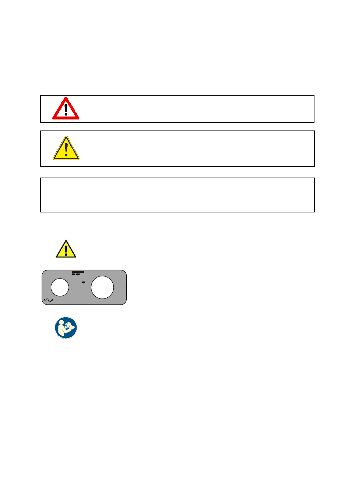
WARNINGS, CAUTIONS AND NOTES
Care must be taken in referring to this manual so as to ensure adherence with all warnings,
cautions and important notes. These carry information related to the safety of personnel and
the integrity and satisfactory operation of plant.
WARNINGS: THESE ARE INSTRUCTIONS THAT DRAW
ATTENTION TO THE RISK OF INJURY OR DEATH.
Cautions: These are instructions that draw attention to the risk
of damage to the product, the process, the equipment or the
surroundings.
Important: These are instructions that draw attention to information
that will aid installation, operation or maintenance.
!
Labels affixed to PCM
Fuse
DC
F4A
H250
Caution label attached to Battery cover
VDC
Label indicating DC power and Fuse rating
Label indicating refer to manual
5
Page 6

Contents
Page
Preface 2
Declaration of Conformity 4
Warnings, Cautions and Notes 5
Section 1: PCM500 and PCM500W
Specification and Requirements
1.1 General Description 7
1.2 Fluid Environment 7
1.3 Ambient Environment 8
1.4 Electrical Requirements 8
1.5 Fluid System Connections 8
1.6 Product Specification 9
Section 2: PCM500/PCM500W Inspection
and Packaging. 10
Section 3: PCM500/PCM500W Description
of Monitor. 10
Section 4: PCM500/PCM500W Principles
of Operation
4.1 General Principles 11
4.2 HMI Control Panel 11
4.3 Test Sampling 11
4.4 Communication Panel 12
4.5 Power Schematic 12
4.5 Battery 13
Section 5: PCM500/PCM500W
Connecting the Monitor
5.1 Connection Options 14
5.2 Connections 15
5.2.1 High Pressure Line 15
5.2.2 Low Pressure Line 15
5.2.3 Reservoir Sampling 16
5.2.4 Bottle Sampling 16
5.3 Operational Checks 17
5.4 Installation Checks 17
Section 6: PCM500/PCM500W
Getting Started
6.1 General 17
6.2 System Requirements 17
6.3 Screen Button Description 18
6.4 The Screens Flow Chart 19
6.5 Example Screen 20
6.6 Start-up Sequence 20
6.7 Sampling 21
6.8 Test Point and Fluid Setup 23
6.9 Code Alarm Set-up 25
6.10 Data manager Screens 25
6.11 Tools Screens 27
Section 7: Interface Protocol – PLC
control through DB9 Serial Port 30
Section 8: PCM500 / PCM500W Fluid
Change Procedure 33
Section 9: PCM500 / PCM500W Function
Codes and Corrective Actions 34
Section 10: PCM500 / PCM500W Spare
Parts List 38
Section 11: PCM500 / PCM500W
Cleaning, Maintenance & Disposal of
Equipment 39
Appendix A: Calibration and Aftermarket
Services 40
Appendix B: PCM500/PCM500W Mesh
Manifold Exchange procedure 41
Pall World wide warranty 43
6
Page 7

Section 1: Pall PCM500 and PCM500W Fluid
Cleanliness Monitors
Specification and Requirements
1.1 General Description
The Pall PCM500/PCM500W is specifically developed as a portable diagnostic
monitoring device that provides an assessment of system fluid cleanliness. A fixed
display/controller allows for simple menu driven input of sample identification, monitor
configuration and data output in ISO4406, SAE AS 4059 Table 1 (NAS 1638) or SAE
AS 4059 Table 2 formats. The display/controller shows the test results, an option to
graph results and this data is automatically stored for subsequent trending and
evaluation. The self-contained design provides for a portable fluid contamination
monitor that can be used with a range of fluids including mineral oils and aqueous
solutions. Note: The PCM500W should not be used for aqueous solutions.
Fluid change procedures are included in this manual and these help to ensure the
PCM500 monitor is adequately flushed ready for an alternative fluid application
See Pall Datasheet M&EPCM500EN for full technical specification
The full technical specification is given below.
1.2 Fluid Environment
Operating Pressure range 0 to 315 bar (4,570 psi) maximum
Operating Viscosity range 1.5 to 450 Centistokes (30 to 2,200 SUS)
Operating System Mineral Oils 10C - 80ºC (50°F - 176°F)
Temperature Water Glycols 10ºC - 60ºC (50°F - 140°F)
Water Based Fluid 10ºC - 60ºC (50°F - 140°F)
Fuels 10ºC - 40ºC (50°F - 104°F)
Industrial Phosphate
Esters & Polyesters 10ºC - 80ºC (50°F - 176°F)
Be aware of possible danger associated with high oil temperatures and
exposed metal surfaces of the PCM500
Fluid Compatibility
Aqueous solutions having a pH <11.0, water glycols, high water based
fluids, petroleum based fluids, industrial phosphate esters, mineral oils
and synthetic fluids.
Do not use Acetone based fluid.
Seals Fluorocarbon (Viton)
WARNING: Health and Safety.
Observe caution when handling fluids and pay attention to instructions of
safe use in the Material Safety Data sheet and COSHH regulations.
Wear protective clothing if prescribed; e.g. safety gloves, clothing and
footwear.
Caution: Health and Safety.
Ensure there is adequate lighting to operate the equipment.
Observe local regulations for factory use.
7
Page 8

Section 1: Pall PCM500 and PCM500W Fluid
Cleanliness Monitors
Specification and Requirements
1.3 Ambient Environment
Operating Temperature range 5°C - 40°C (41°F - 104°F)
Storage Temperature range
(Monitor drained of fluid) -20°C to 55°C ( -4°F to 131°F)
Dust and water protection IP65 (NEMA 4)
Relative Humidity 95%rh non-condensing
Operating Altitude <2000 metres
WARNING: Do not use the PCM500 Series Monitor in an explosive
atmosphere
1.4 Electrical
External Mains Power Supply Unit Input 100 – 240 VAC (Auto Ranging)
(PSU) Accessory Frequency 50 – 60 Hz Single Phase.
Output 48V DC
Input Fuse Quick Blow, 4A 5x20mm (250V)
Optional Mains Supply Unit Input 100 – 240 VAC (Auto Ranging)
Frequency 50 – 60 Hz Single Phase.
Output 24VDC
Internal Battery 12VDC Lithium Ion rechargeable.
Battery Life Typically 35 - 40 samples depending on
cleanliness levels & oil viscosity
Communications USB 1 (Data Acquisition)
USB 2 (PC Setup of PCM)
USB 3 (Printer)
Ethernet Cat5 (Remote control & Data
Acquisition)
RS232C (PLC Control)
Voltage Free Contacts
(Alarm output – contact rating 1 Amp @
24VDC)
1.5 Fluid Connections
Inlet – 2 options High Pressure:
Hose with ¼” BSP female swivel fitting and Metric,
Imperial or NPT Test Point connector options.
Low Pressure:
Hose direct coupled on ¼” BSP female swivel fitting.
Sampling stalk (for bottle sampling)
Outlet M10 male fitted to 6mm OD. Clear plastic hose, with
straight adapter and cap.
8
Page 9

Section 1: Pall PCM500 and PCM500W Fluid
Cleanliness Monitors
Specification and Requirements
1.6 Product Specification
Weight 11 Kg (24 lb)
Dimensions 400 x 260 x 250 mm (15.75” x 10.2” x 10“)
Monitoring range ISO4406 11/9/7 to 23/21/17
Monitoring range SAE AS4059F Table 1
(NAS1638) 1 to 12
Monitoring range SAE AS4059F Table 2 >4µm: 1 to 12, >6µm: 1 to 12 and >14µm:
1 to 12
Accuracy ±1/2 ISO4406 Code
Water-in-Oil (PCM500W only) %rh. ± 2% at 5 to 95%rh (non-condensing)
(PPM switchable but requires C1, C2, 0 to 100% full range
C3 & C4 fluid constant input. Contact
PALL representative).
Enclosure Material and Flammability ABS UL94 V-0
Enclosure Gasket Seals Silicone Rubber
Noise Level <70 dBA
Foreseen misuse of equipment
Within this manual are cautions and warnings to highlight potential dangers associated
with operation of the PCM500. Here are a few points of note on misuse of the
equipment.
A danger to the user can arise from connecting the PCM500 to a pressured system
above the working limit, and / or, using an incorrect high-pressure connection.
Damage to the PCM500 can occur from using incompatible fluids.
A danger to the user and damage to the PCM500 can be from an incorrect mains
voltage supply.
9
Page 10
Section 2: Pall PCM500 and PCM500W
Fluid Cleanliness Monitors
Section 3: Pall PCM500 and PCM500W
Fluid Cleanliness Monitors
2.1 Inspection and Packaging
The PCM500 is shipped in a transportation
case. Use this case for re-shipping the PCM.
Visually inspect the case for signs of external
damage that may have occurred during
shipping and bring any damage to the
attention of the shipper.
Inspect the interior of the case for damage to
the contents as listed below. Compare the
contents of the case with the shipping papers
to assure all the content is present. If any
items are missing, contact Pall or an
approved agent.
The PCM500 package comprises of:
• Integrated PCM500 series monitor with
sample hoses
• Power supply unit
• Mains power lead
• PCM500 to PC communications cable
• PCM500 series Operating Instructions on
CD ROM
• PCM500 series Quick Reference Guide
• Fluid Sampling stalk
• High Pressure test point connector
(Choice of Imperial, Minimess or NPT)
• Certificate of Conformity
• Certificate of Calibration Verification
• Packing note checklist
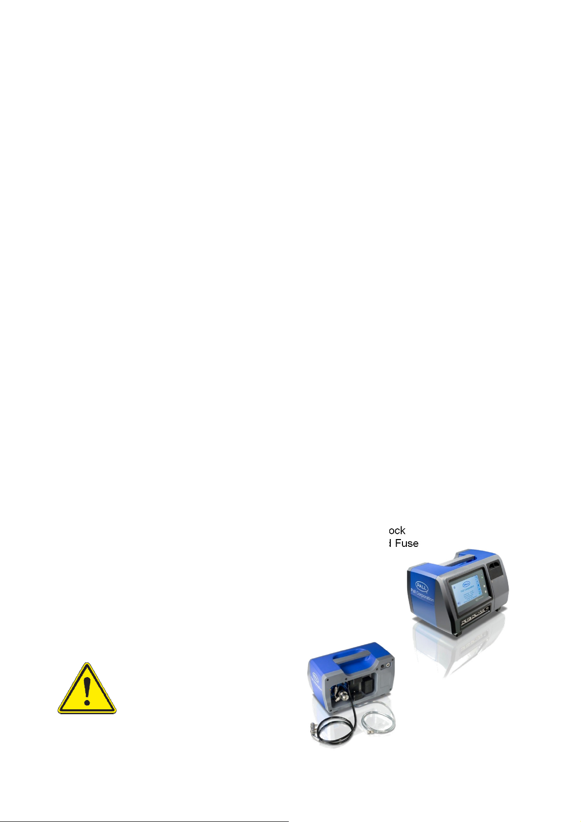
3.1 Description of the Monitor
The PCM500 is designed and built for light
Industrial use while maintaining aesthetic
and user friendly ergonomics. See section 1
for full specification. The materials are
selected to meet the various fluid and
environmental conditions that the PCM500 is
likely to be subjected during operation.
As a self-contained unit, including sampling
hose and adapters, the user is able to
connect the PCM500 on-line or sample fluid
directly from a system reservoir without
breaking lines thereby avoiding extraneous
contamination.
The PCM500 cleanliness monitor provides
numerous display functions to assist the user
at all stages of operation and provides
function codes to warn of any problems with
both the PCM500 and system fluid.
1. HMI (display/controller)
2. Communication Ports
3. Robust case with carry handle.
4. Integral 12VDC battery
5. Printer storage compartment
6. Last Chance Filter Housing
7. Hose Storage
8. Mesh Screen block
9. Power input and Fuse
The instruments’ specific serial number and
calibration/service record sheet is also
included. It is important to keep this in a safe
place and return them with the unit for future
annual service requirements.
Caution: Health and Safety.
Ensure there is adequate
lighting to operate the
equipment.
Observe local regulations for
factory use.
❻
❼
❽
❾
❸
❶
❺
❹
❷
10
Page 11
Section 4: Pall PCM500 and PCM500W
External power connected and
Series Fluid Cleanliness Monitor
Principles of Operation
4.1 General Principles
Upon starting a test sequence the PCM500
will self-prime and perform internal checks on
the sample fluid condition. This is an
automatic part of the test time. After
approximately 30 seconds the PCM500 will
start the analysis. The screen will display a
progressive time bar for the duration of the
sampling period and identify the specific
stage in the monitoring cycle above the
progress bar.
During the analysis cycle the sample fluid is
presented to mesh screens in a specified
sequence, which captures contamination that
is larger than mesh pore size.
Particle concentrations are measured and
computed for each specific mesh.
BUTTONS:
• START/STOP/REPEAT (test)
• ON /OFF
The test Start/Stop button is active on
release. The ON button is active on
release but OFF requires pressing for 2 3 seconds to shut down.
Blue LED
On Off Flash On On
x
4.3 Test sampling
Green
LED
x No external power (battery
x PCM500 On - Operational /
Red Description
battery in charge mode.
only)
Standby
x Test in Progress
x Hardware/Sampling problem
detected
During the sampling sequence, data is
constantly analysed to identify any excessive
variance in temperature, viscosity, and
pressure to ensure results are not spurious.
The PCM500 will advise the user by function
codes, if any excessive variance occurs.
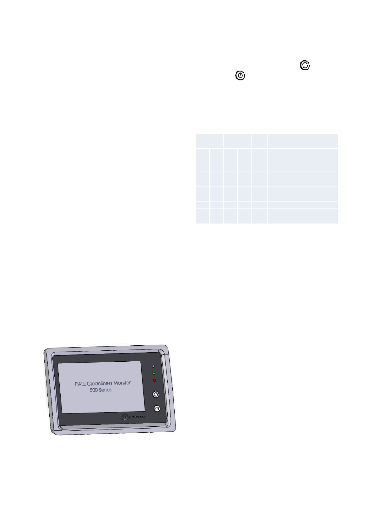
4.2 HMI Control Panel
The HMI LCD display is designed to provide
clear viewing of the screen menus and test
data. The test sample sequence is initiated
by use of the primary function keys. In edit
mode a keyboard is displayed on the screen,
which enables users to enter, or edit data
including sample points and fluid types.
There are three light emitting diodes (LED) to
indicate PCM500 operational status and two softtouch control buttons.
11
Page 12
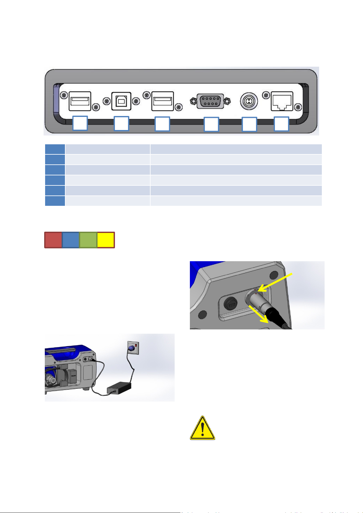
4.4 Communications Panel
1
1 USB-A Socket 1 Text file upload/download from memory device
2 USB-B Socket PC connection for setup/control of PCM500
3 USB-A Socket 2 Printer connection
4 DB9 Female RS232 / PLC control (See section 7)
5 2-Pin Socket Voltage free contact. Relay
6 RJ45 Cat5 Ethernet 10/100 base
Screen indication of valid port connection
2
3
An indication of battery charge can be seen
in the lower right corner of the display.
4 5
U E PR
A row of four small boxes in the bottom right
corner of the display screen indicates when a
port connection is active.
U = USB-A 1
E = USB-A 2
R = RS232/PLC
P = Ethernet
External Supply
6
Align the red
dots and push
to connect
4.5 Power Schematic
The PCM500 is normally powered by a
battery located in the front of the unit behind
a plain panel. This has capacity at full charge
to power the monitor for an average of 40
tests (depending on oil viscosity). A power
supply unit (PSU), supplied as part of the
PCM500 package, allows the monitor to be
run from mains power and to charge the
battery.
!
Grip connector outer body and
pull straight to disconnect.
Important:
The PSU cable connection uses a
push – pull action on the outer body
and both connector and receptacle
align through a ‘red dot’ location mark.
DO NOT attempt to remove by rotating
the connector.
Important:
The monitor should not be operated
with the battery pack disconnected.
If a power outage occurs on mains
supply during testing the battery will
maintain power to the PCM to
prevent loss of data and allow for a
safe shut down
12
Page 13
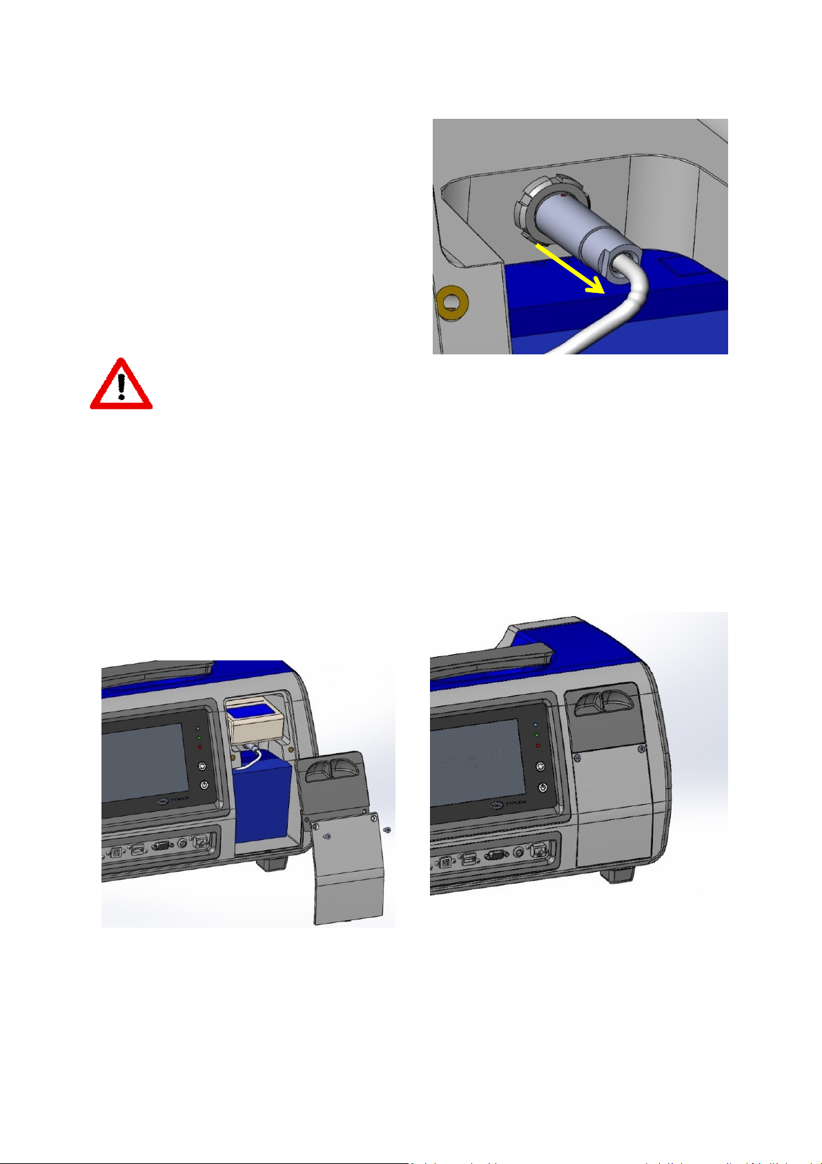
4.5 Battery
Important:
The monitor should not be
!
In the event of a battery replacement the
following procedure should be followed.
operated with the battery pack
disconnected. If a power outage
occurs on mains supply during
testing the battery will maintain
power to the PCM to prevent
loss of data and allow for a safe
shut down.
WARNING: Use only battery
packs supplied by the
manufacturer or Pall agent.
Serious damage will occur if a
battery of different chemistry or
specification is used.
4. The battery connector is removed by
pulling straight on the outer body. Do not
rotate the connector, otherwise damage
will result.
5. When connecting the new battery,
align the red dots between connector and
receptacle before insertion.
1. Ensure the PCM500 is OFF and the
external mains power supply disconnected.
2 . Remove the two M4x10 hex socket
screws from the battery cover and lift out the
cover and then the printer storage cover.
6. Replace the printer and battery covers
and fix with the M4 hex socket screws.
3. Remove the printer if present to allow full
access to the battery connector
13
Page 14

Section 5: Connecting the PCM500
5.1 Connection Options
A general checklist for the user before
starting is given in section 5.3 and also in the
‘Useful information’ quick reference card for
PCM500 unit.
PCM500 is configured for two hose
operation, inlet and return and these are
stored within the rear of the instrument. The
high-pressure hose is used for both high and
low-pressure sampling. Fluid entering the
PCM500 is filtered for contaminant larger
than 65µm diameter by a mesh cartridge
element (Last Chance Filter). This element is
user changeable. In the event of a blocking
filter, fluid entering the PCM will be restricted.
The PCM will detect a loss of fluid and
produce an error code and message on the
display.
Caution: In the interests of
safety, always remove the
end cap from the return line
before connecting the inlet
hose to high-pressure. If the
PCM Pressure Reduction Valve does not
regulate properly then excess outlet pressure
can escape through a relief-valve into the
return line.
NEVER LEAVE A PCM CONNECTED TO
HIGH-PRESSURE WITH THE RETURN
LINE CAPPED.
If the return line is capped or blocked and a
fault occurs with the Pressure Reduction
Valve, then to prevent damage to the internal
circuit a secondary relief valve will exhaust
through a diffuser element at the rear of the
PCM above the return outlet. It is important,
therefore, to be aware of a possible loss of
system fluid.
See the below image of diffuser location.
The sample take-off point in pressure
systems should be cleaned of contaminant
before connecting the PCM hose and in both
high and low pressure sampling modes the
return line must be unrestricted and allowed
to drain into a waste container or system
reservoir.
The PCM500 can be connected in various
ways. High-pressure mode is considered to
be the most appropriate to achieve
representative sampling.
It is important to note that due to the very
small bore through the high-pressure
connector it must be removed from the inlet
hose when sampling below 1 bar pressure. If
not, an error may occur through insufficient
fluid flow into the PCM.
When sampling a closed system, it is
advised to flush the PCM with one test to
waste to prevent cross contamination by fluid
remaining in the PCM from a previous test.
Safety Relief Exhaust Point
Caution:
Do not position the PCM that
makes it difficult to disconnect
power.
14
Page 15

5.2 Connection Options
5.2.1 High Pressure Line (>1 to 315 bar)
5.2.2 Low Pressure Line (0 - 1 bar)
<1 bar at test point: - remove HP connector and
couple hose direct.
15
Page 16

5.2 Connection Options
5.2.3 Reservoir Sampling (0 bar: - Direct coupled hose or use sampling stalk. Remove
high-pressure connector)
Note: Ensure sample point and hose connection are
cleaned before mating
5.2.4 Bottle Sampling (0 - 1 bar)
When sampling from a bottle or container, it is
advised to run a single test to waste with a
clean, compatible fluid (≤ ISO 12/10/8) and
remove any residual contaminant from the
PCM500. Depending on viscosity and
cleanliness, the PCM500 may require up to a
litre of fluid sample for a bottle test. Always
ensure the containers are thoroughly cleaned
prior to introducing a fluid sample..
When bottle sampling it is important to prevent
extraneous contaminant entering the sample,
such as may be found on the outer surface of
the HP hose connection. It is advised to use
the sampling stalk provided, which should be
kept in a clean condition.
In order to check the repeatability of
cleanliness results, a large sample (>3 Litre)
may be cycled into the same container and
averaged over a 3-test run for example.
16
Page 17

5.3 Operational Checks
5.4 Installation Checks
Preparation checks before going to the
installation to be sampled.
Caution: The PCM500
display touch sensitive
screen must not be pressed
with a sharp or pointed implement.
Finger contact is sufficient to operate the
display menu icons and keyboard.
Press and release the PCM500 start button
The Control panel green LED
will flash within a few seconds
and the PCM500 enters the
start-up phase. After a short period the
display will turn on and a screen will appear
with Pall logo. The next phase of start-up is
test firing of the internal valves (six clicks).
Following this the main menu screen is
visible.
If the PCM fails to power up on battery,
connect the external PSU and check the blue
LED on the front panel is ON. If not, check or
replace the input fuse with the correct value.
If the PCM fails to start, consult Pall.
First screen
At installation to be sampled
1) Access the hoses at the rear of the
PCM500.
2) Ensure the hose connectors are clean
and free from any visual contaminants.
3) Ensure the installation to be sampled is in
operation and has been running for a
minimum of 30 minutes prior to taking the
sample in order to distribute the
contamination as evenly as possible
within the fluid. This is necessary to allow
a representative fluid sample to be taken.
4) Connect the clear return line hose to the
system reservoir or suitable capacity
container ensuring cap is removed
5) Connect the black hose to the
appropriate sampling point. Check for
any leakage, rectify as required.
Warning: Ensure the
system operating pressure
is within the PCM500
monitor specified limitation of 315 bar,
4,570 psi maximum.
6) The PCM500 can now be switched on
and the screen sequence followed. The
specific procedure for start-up is detailed
in section 5.4 and section 6 ‘Getting
started’.
2. If the PCM500 has been used previously
with a different fluid to the new sample then
fluid change procedures detailed in section 7
should be adopted.
3. Switch off the PCM500 and you are now
ready to proceed to the installation to be
sampled.
Section 6: Getting Started
6.1 General
This section of the operating instructions
enables a new user to perform tests using
the PCM500 Cleanliness Monitor in a short
space of time. It does not instruct the user in
sampling techniques and the user should
consult Pall for guidance on recommended
sampling points.
6.2 System Components
• PCM500 Cleanliness Monitor
• Power Supply Unit
• Battery Pack
• Bluetooth / USB Printer (Option)
17
Page 18

6.3 Button Descriptions
Main
Menu
Navigation
Editing &
Data
Warnings
Tools and
Functions
Communication
Testing
Home
Previous
Delete
Critical
Set Label
Export
Set-up
Confirm
Create
Warning
Clock
Bluetooth
Setup
Tools
Undo
Open
Shutdown
Date
Wi-Fi Setup
File Info Language
Cancel Up Down
Edit
Contact
Format
Comms
Port
Print
ISO 4406
Format
Forward Back
Temp.
Format
AS 4059
Format
Data
Management
Information
Test Point
Upload to
Flash Drive
PCM500
Spec
Fluid
Download
to PCM
Mesh
Settings
Test Label
Test Label
Battery
Data
Water in Oil Repeat
Result
Warning
Control
Panel
Select All
Comms.
Ports
Alarm Set-up
Graph
18
Page 19
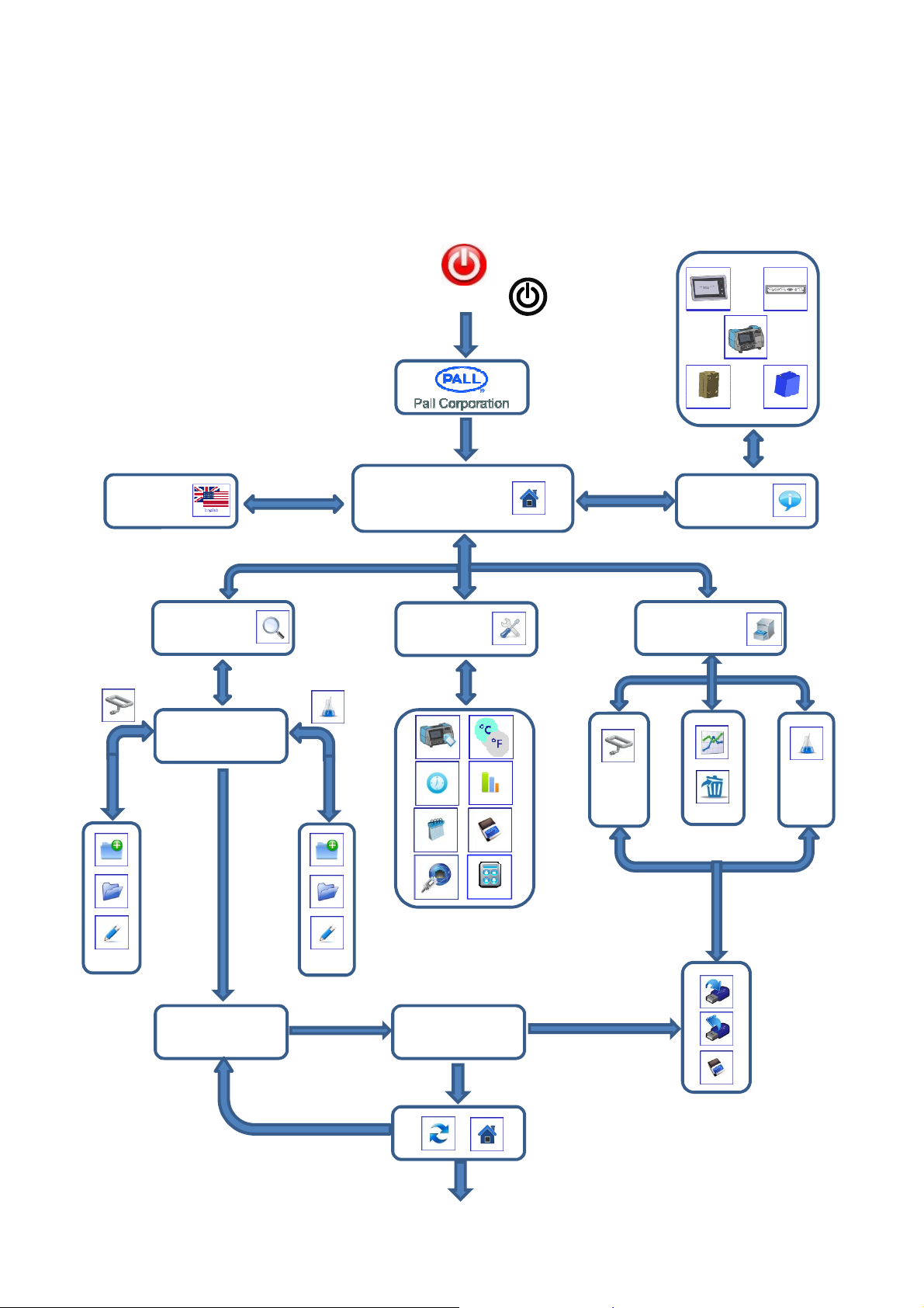
6.4 Display Flow Chart
The display flow chart can be used to help the new user become familiar with the PCM500
display operating sequence. The flow chart consists of a number of views using the
previous Icon listing to indicate their access within the screens.
START
Language
Current setup
Testing
MAIN MENU
Tools
Information
Data Manager
Test
Result
19
MAIN MENU
Page 20

6.5 Example Screen
The screen below is an example of those
that will be seen when using the PCM500.
An explanation of common keys is
incorporated here to prevent repetition.
The screens are structured into four main
groups; Testing, Tools, Data Manager and
Information. The home key will always return
the user to the main menu. There is a flag
icon that denotes the language setting. Use
this active icon to change language setting.
An example screen shot of the PCM500 main
menu:
If the PCM500 is out of calibration, requires
an annual service or other intervention a
warning screen will inform the user at startup. This is to ensure the user keeps the
PCM500 fully serviced and helps ensure the
integrity of the high-pressure part of the
instrument.
Calibration Expired
Mesh Test Limit Exceeded
Press the contact button to open a contact
details screen or proceed to home (Main
Menu).
PCM500W – SERIAL No. 2345
MESH TEST REMAINING: 1234
CALIBRATION DUE: 2016/10/24
CUSTOMER OR UNIT IDENTITY HERE
6.6 Start-up Sequence
Press and release the power on/off button
on the front panel. This will power-up the
PCM500 monitor and the green LED light will
flash for several seconds. Whilst the unit
powers up, the display will activate and the
following screens appear:
Splash screen
PALL CORPORATION
WWW.PALL.COM
Support / Contact Pall
Contact screen for technical support
In the event of a major fault the next screen
will appear and the PCM must be closed
down and the problem reported to your local
distributor or Pall Corporation.
HARDWARE FAULT
REFER TO MANUAL
20
Page 21

Main Menu Screen
PCM500W – SERIAL No. 2345
MESH TEST REMAINING: 1234
CALIBRATION DUE: 2016/10/24
CUSTOMER OR UNIT IDENTITY HERE
The main menu includes PCM500 serial
number, mesh test detail, calibration date,
and customer or unit identity if installed.
To the right hand side are buttons to access
menus for testing, tools, data manager and
information,.
6.7 Sampling
Sample can be on-line, from a reservoir, or
bottled oil sources. Refer to sections 1
‘Specifications and section 5.1 ‘Connection
Options’.
On Line or Tank Sampling Routine
From the main menu
press the test button
The user will be presented with a Test
Configuration screen. If the parameters are
correct then advance to the next screen
using the right arrow button. To edit or
change the setup select one of the top three
left hand buttons.
The time and date and a 5-stage battery
indicator is in the lower right corner.
To the bottom left is a button icon indicating
the languages that are available. Press to
select a different language.
Language select screen
Languages are installed for the following
countries.
• Denmark
• Finland
• Norway
• Sweden
• Netherlands
• Poland
• Portugal / Brazil
• Italy
• Germany
• France
• Spain
• USA / UK
Test Point screen:
TEST POINT NAME
FLUID NAME
TEST LABEL
Final Check Screen:
TEST POINT NAME
FLUID NAME
TEST LABEL
START
Check the parameters are correct then Start
test using RIGHT arrow button.
21
Page 22

Warm Up Screen example.
A single test result screen
If the sample fluid temperature is below the
value set in Test Point, the PCM will enter a
warm-up cycle which pumps fluid
continuously until the temperature measured
in the PCM circuit is at the target
temperature.
TEST POINT NAME
TEST 1 OF 3
WARM UP
24°C TARGET 45°C
WATER IN OIL 50%rh
Important: The PCM can
tolerate up to a 1°C per
!
minute change in sample
temperature during a
measurement cycle. It is
important, therefore, to stabilise PCM
temperature close to the system temperature
for measurement accuracy.
Once into the test measurement a progress
screen provides real-time test data. The test
can be cancelled at any time through the
Cancel button icon.
RESULT
TEST NAME: NEW OIL
TEST POINT: LUBE RESERVOIR
FLUID: 32 GRADE
CODE: ISO4406 21/18/14
WATER IN OIL 50%rh
TEMPERATURE: START 25°C END 26°C
TIME & DATE: 12:15 2015/10/24
WARNINGS:
NONE
Screen for multiple test results.
UP and DOWN buttons allow access to all
test results in the sequence. The results are
automatically saved to memory and can also
be viewed through the Data Manager
screens.
The options from the result screens above
are to transfer on USB; Print; Repeat the test
sequence or return to the Home screen.
RESULT 3 of 3
TEST NAME: NEW OIL
TEST POINT: LUBE RESERVOIR
FLUID: 32 GRADE
CODE: ISO4406 21/18/14
WATER IN OIL 50%rh
TEMPERATURE: START 26°C END 27°C
TIME & DATE: 12:30 2015/10/24
WARNINGS: NONE
The first measurement in the test cycle is
14µm particulate followed by the 6µm.
Temperature and Water-in-Oil (PCM500W)
data is provided and also details of the
previous result code, if a multiple test
sequence is running.
TEST POINT NAME
TEST 2 OF 3
6µm SAMPLING
24°C (MINIMUM IS 15°C)
WATER IN OIL 50%rh
LAST
TEST:
WARNINGS: NONE
Should any test parameters be exceeded
during a test a ‘Warnings Present’ label will
be shown at the bottom of the screen. These
will be recorded in the final test result detail
screen.
Transfer via USB will be to a Flash Drive /
Memory Stick connected to a USB-A port on
the COM port panel. Press the Tick button to
upload and a progress bar indicates the rate
of transfer. Press the Return button to go
back to the results screen.
Upload to Flash Drive?
22
Page 23
Print results screen
New Test point set-up
This follows the same control method as
USB transfer but there is an option to print
one or all results if multiple tests are
available. If one is selected then it will be that
currently open on the result screen.
3 RESULTS
PRINT ONE OR ALL
PRINTING RESULT 3 OF 3
6.8 Test Point & Fluid Setup
If a new Test Point or Fluid is to be created
for loading into the test setup or the current
settings require editing, this is done through
the Test Setup screens,
TEST POINT NAME
NEW TEST POINT
TEST POINT NAME = RESERVOIR
NUMBER OF TESTS = 3
MINIMUM TEMPERATURE (°C) = 10
CODE ALARM (ISO) = 18 / 16 / 13
TEMPERATURE ALARM (°C) = 70
WATER-IN-OIL ALARM (%rh) = 60
Use UP and DOWN arrows to select a
parameter and press EDIT for the following
action:
• Test Point name switches to qwerty
keyboard screen
• Number of tests, minimum temperature
and trigger time switches to calculator
screen
• Code alarm screen is determined by the
code format selected (Tools Screens)
• Temperature and water-in-oil alarm points
are edited on the calculator screen.
• Save the setup using the tick button.
• To return to test setup screen or, cancel
editing without saving use the Return
button.
FLUID NAME
TEST LABEL
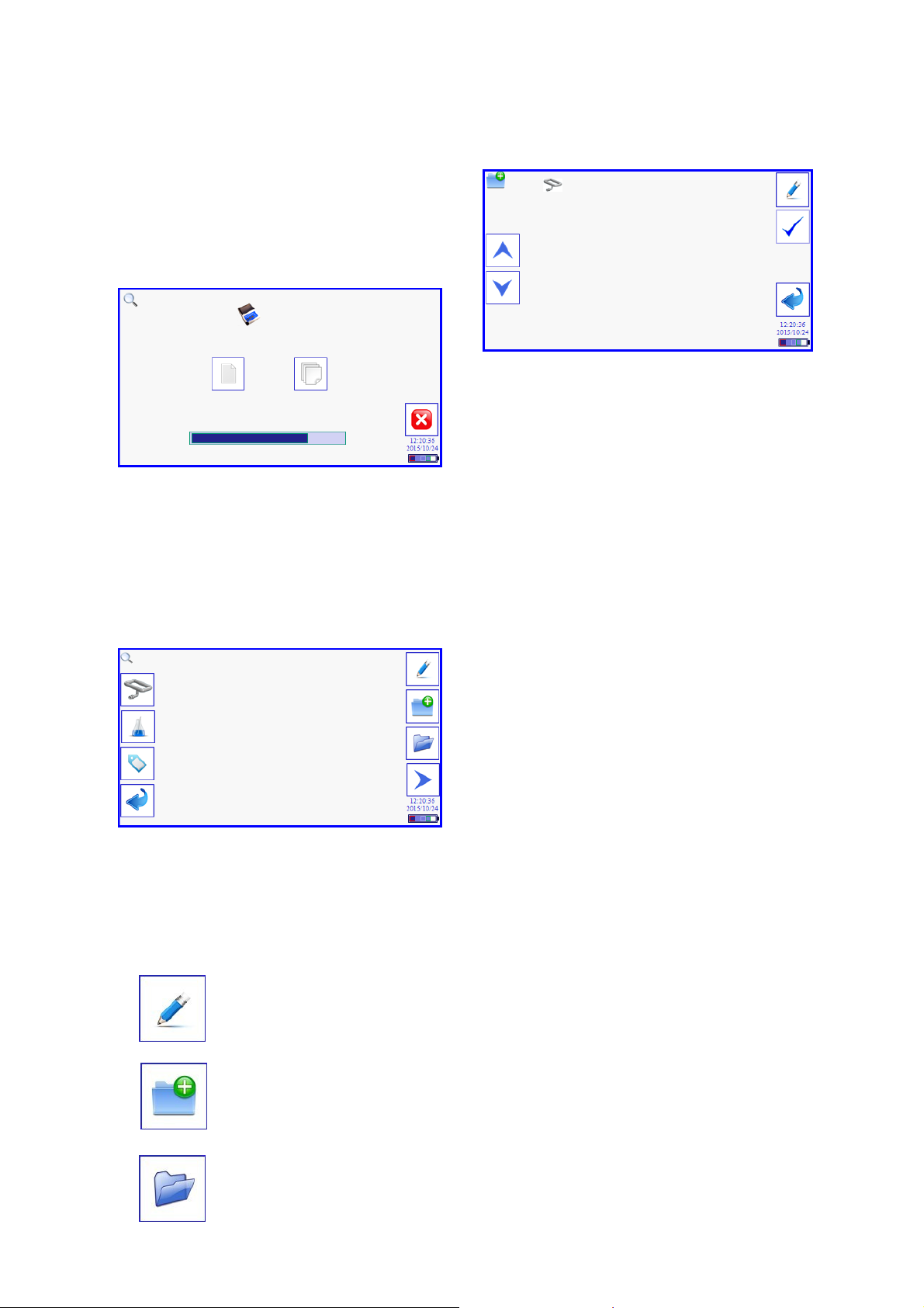
For example, if either the Test Point or Fluid
buttons are pressed it activates a set of
options to the right of the screen. Using the
Test Label button will open the QWERTY
keyboard.
Edit key to change values in
Test Point and Fluid setup
Create New for Test Point or
Fluid
Open an existing Test Point or
Fluid setup
Important: The trigger period
!
The minimum set time is 7 minutes, which
includes the maximum allowable test period
and a 1 minute delay. e.g. Trigger time=7
min. test time=6 min. time from end
of test to the beginning of the next test = 1
min
If a test is started by external control, such as
from a PLC, then the trigger period can
remain at 0 minutes.
!
The PCM500W monitor must not be used
with water bearing fluids. The PCM500 does
not incorporate a water sensor
begins at the start of one test
to the beginning of the next.
Important: The water content
alarm is applicable to the
PCM500W monitor only.
23
Page 24

If a Test Point with the same name already
exists a warning screen will appear to
overwrite the old setup.
NEW TEST POINT
TEST POINT ALREADY
CREATED
REPLACE WITH NEW
SETTINGS?
Fluid setup screen
accessed through the Fluid
button.
• Select Fluid name to edit through the
QWERTY keyboard (enter/edit the name}.
• For PCM500W a water-in-oil entry is active
and toggles between %rh and PPM on the
press of the Edit button. If PPM is selected
then four absolute water constants appear for
editing. C1, C2, C3 and C4 are updated
using values supplied by Pall Corporation,
contact Pall for availability.
• Save the setup through the tick button and
use the Return button to go back to the Test
Point screen.
QWERTY Keybaord
Number Entry screen
Load a stored Test Point
From the OPEN button in Test point, select a
stored Test Point and make current by
pressing the TICK button.
NEW FLUID
FLUID NAME
%rh OR PPM
C1 CONSTANT (PPM)
C2 CONSTANT (PPM)
C3 CONSTANT (PPM)
C4 CONSTANT (PPM)
TEST POINTS
TEST POINT A
TEST POINT B
TEST POINT C
TEST POINT D
TEST POINT E
TEST POINT F
Load a stored Fluid
From the OPEN button in Fluids, select a
stored Fluid and make current by pressing
the TICK button.
24
Page 25
FLUIDS
FLUID A
FLUID B
FLUID C
FLUID D
FLUID E
FLUID F
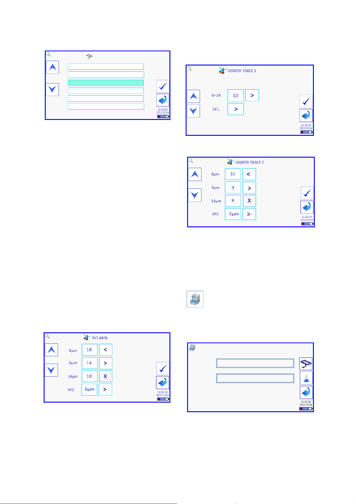
6.9 Code Alarm Setup
AS4059 Table 1
Each Test Point is allocated an alarm point
setup for the three coding standards and
whether a two or three-part code is selected.
The default alarms are set to maximum code
numbers and the user can adjust the code
alarms to their required limits.
If a different code standard is selected the
alarm points change to that standard also.
The VFC (Voltage Free Contact) is a two pin
socket on the PCM communication panel
(see section 4.4). A signal can be taken on
an alarm state to control the switching in or
out of a filtering system for example. In the
example below, the alarm is set to trigger if
6µm is greater than ISO 14 code. This could
signal the start of system filtration pumps.
To change a code number, touch to highlight
and use the UP and DOWN arrows.
To change an alarm action the options are <,
> and X (not applicable).
Example: ISO4406
AS4059 Table 2
6.10 Data Manager Screens
Any results saved on the PCM500 can be
viewed and managed using the data
manager. To get to the data manager press
the data manager button in the main menu.
The data manager displays the
current Test Point and Fluid.
Press the Test Point button to access data.
DATA MANAGER
TEST POINT B
RUST VETO NTP32
A list of all Test Points is now available to
Graph, Transfer or Delete.
25
Page 26

TEST POINTS
TEST POINT A
TEST POINT B
TEST POINT C
TEST POINT D
TEST POINT E
TEST POINT F
This button will graph all
results under a selected Test Point using the
current Code Format
Opening an individual Test
Point lists all tests under that
name. Single or All Test
Labels can be loaded to USB Flash Drive or
printed
TEST POINT B LABELS
RESERVOIR FILTER-IN
RESERVOIR FILTER-OUT
NEW OIL
NO LABEL (DEFAULT)
SAMPLE 2015-10-02
TEST RIG
TEST POINT B
TESTS
Flash Drive button will give a choice
of uploading or downloading Test
Point data
TEST POINTS
TEST POINT A
TEST POINT B
TEST POINT C
TEST POINT D
TEST POINT E
TEST POINT F
Upload to Flash Drive screen allows
individual or All Test Points for
selection.
Open an individual Test Label to view
individual tests. Then open and view the
result in detail
NEW OIL
DATE
TIME
RESULT
Individual Test detail can be uploaded to
Flash Drive or Printed. A flag to the side of a
test indicates a warning is attached
NAME: NEW OIL
TEST POINT: B
FLUID: MINERAL OIL
CODE: ISO4406 16/13/10
WIO (%rh): 50
TEMP (°C): START 25 END 26
DATE & TIME: 2015-10-25 14:15HRS
WARNING:
203 LOW BATTERY
RESULT
SELECT TEST POINT
TEST POINT A
TEST POINT B
TEST POINT C
TEST POINT D
TEST POINT E
TEST POINT F
26
Page 27

Deleting
Throughout the data management screens
there are several that include the delete
option. This includes Points; Names; Tests
and Fluids. To enable this action a password
must be entered. The default password
issued is DEL1 but this can be changed by
the user in the TOOLS screen.
Example:
On pressing the DELETE button under the
Test Label screen the screen header
changes. The user may now select Label(s)
by pressing the DELETE button and these
remain highlighted. When the selection is
complete the TICK button is pressed to go to
a password screen.
SELECT TO DELETE
RESERVOIR FILTER-IN
RESERVOIR FILTER-OUT
NEW OIL
NO LABEL (DEFAULT)
SAMPLE 2015-10-02
TEST RIG
The password is entered and TICK button
pressed
DELETE SELECTION?
DELETE FLUID OR TEST OR NAME OR POINT
6.11 Tools
• PCM Label (Edited through the QWERTY
screen)
• Code Format
• Remote Assistance
• Printer Test
• Calculator
• Temperature (Press to toggle between
Fahrenheit and Celsius)
• Date
• Time
This next screen is a last chance before the
data is removed. Pressing the TICK button
removes the selected data. To abort this
action the back arrow or Home button is
pressed.
PCM Label
This is entered through the
QWERTY keyboard and can be up
to 40 characters in length
UNIT IDENTIFIER IF REQUIRED
27
Page 28

Code Format
There are several options for Code format
within the three standards provided.
• ISO 4406 -/6µ/14µ (2-part)
• ISO 4406 4µ/6µ/14µ (3-part)
• AS4059 Revision F Table 1
• AS4059 Revision F Table 2 Size 6, and 14
• AS4059 Revision F Table 2 , Size 4, 6, &
14
Temperature
Temperature reporting is changed by simply
pressing the button to switch between
Fahrenheit and Celsius
Remote Assistance
Time
Time is set to a 24 hour clock and can also
be synchronised to a network clock using the
network clock button. The PCM must be
connected and logged on to a network first.
In manual mode use the left and right buttons
to select hours or minutes
Date
In the course of PCM operation a situation
may arise that requires the intervention of a
PCM Engineer to investigate operational
issues. The Engineer screen provides such
access. Pressing the Remote Assist button
opens a code input screen, in which, the user
enters an access code provided by the
remote Engineer.
Each PCM has its own IP address and to
enable remote access the PCM is connected
to the Internet through a Network or modem
on the Ethernet connection to allow a remote
Engineer to analyse diagnostic data.
REMOTE ASSIST PASSWORD
The date is set using the same screen
functions as in Time setting. Note: - date is
in the international standard format to ISO
8601
Press the Tick button to allow a remote
connection.
REMOTE ASSISTANCE
PCM IP ADDRESS
CO
DE
28
Page 29

Printer Test
To test a Bluetooth or USB connection
between PCM500 and Printer press the
Printer button. A progress screen will open to
show the two connection options. Press the
option required and a corresponding
progress bar indicates the communication
attempt between PCM and Printer. If a
connection is made the Printer will print a
‘Printer Detected’’ message.
TEST
Page 30

Section 7: Pall PCM500 Series Fluid
Cleanliness Monitors
Interface Protocol for PLC control using
DB9 Serial Port.
1. Hardware details
The RS232 settings are: 9600, 8, N, 1
Pin 2 TxD (Transmit Data)
Pin 3 RxD (Receive Data)
Pin 5 GnD (Ground)
Pin 2 and 3 must be crossed over when
using a PC.
C – PCM500 status:
0: The unit is in standby.
1: The unit has ended a test and it is
waiting to start a new test at the set time
interval.
2: The unit is currently performing a test.
D,E,F,G – Latest error codes if any. See
below for details.
[L] – Request last result
The latest valid result is transmitted via DB9
communications port. An example data string
appears like this:
2. Protocol between PCM500 and PLC (or
computer)
The commands available to the PLC or a
computer start and end with a square bracket
as follows:
[P] – “Ping” the unit to see the current status.
[L] – Request last result.
[S] – Start a test.
[A] – Abort a test.
Please note that the command letters are in
UPPER CASE; it will not work with
commands in lower case.
[P] – Ping
The purpose of this command is to verify the
PCM500’s current status.
When [P] is sent, the PCM500 responds with
a comma-separated string, terminated by a
carriage return and a new line.
e.g.
PCM,P,0,00,00,00,00
PCM
P 0 00 00 00 00
A B C D E F G
Where:
A - Label to identify that it is a valid
transmission from the PCM500
B - The P signifies that the transmission
doesn’t contain a result.
PCM, R, 2005/11/20 20:28:00, 1,2,00,00,
00,00,AST1: 11,50,22,10,Test1, 39648
PCM R 2005/11/20 20:28:00 1 2 000
A B C D E F G
0000AST1: 11 502210TEST1 39648
H I J K L M N O
Where:
A. Label sent by the PCM to signify start of
transmission.
B. The transmitted string is a result.
R=Result, A=Aborted test, P=Ping.
C. Date and time the test was performed.
D. Test number in the sequence.
E. Number of tests in the sequence.
F. Error codes (Hex) Byte 1. Hardware
problems. (see below).
G. Error codes (Hex) Byte 2. Sampling
problems. (see below).
H. Error codes (Hex) Byte 3. Sampling
problems. (see below).
I. Error codes (Hex) Byte 4. User defined
settings exceeded. (see below).
J. Result codes as selected on the unit (ISO,
AST1: (AS4059 Table1), or AST2:
(AS4059 Table2).
K. Viscosity.
L. Temperature.
M. Water In Oil (%SAT or PPM).
N. Test Label
O. Checksum.
30
0
Page 31

PCM500 Error codes
The codes are in hexadecimal format.
Byte Code Description
1 0x01 Very low battery
1 0x02 High pulse width
modulation
1 0x04 Viscometer
blocked
1 0x08 Low mesh
differential pressure
1 0x10 Pressure transmitter failure
1 0x20 Temp transducer failure
1 0x40 Internal controller failure
1 0x80 Internal error
2 0x01 Low battery
2 0x02 High line pressure
2 0x04 Low line pressure
2 0x08 Unstable temperature
2 0x10 Unstable viscosity
2 0x20 Unstable sampling
2 0x40 High mesh differential
pressure
2 0x80 Water in oil sensor failure
3 0x01 Water in oil
3 0x02 Memory full
3 0x04 6-micron mesh blocking
3 0x08 14-micron mesh blocking
3 0x10 Mesh test limit exceeded
3 0x20 Calibration period exceeded
3 0x40 Viscosity band mismatch
3 0x80 High viscosity differential
pressure
4 0x01 Solid contamination alarm
4 0x02 Water content alarm
4 0x04 Temperature alarm
4 0x08 Too much contaminant
4 0x10 Test aborted
4 0x20 Test sequence aborted
4 0x40 RESERVED
4 0x80 RESERVED
[S] – Starts a Test
The PCM500 is currently running a test:
the command is ignored.
The PCM500 is in standby: the test series
is initiated, with the maximum number of
tests as previously entered from the display.
The PCM500 is waiting between tests: a
test is initiated and the scheduled test is then
started at the appropriate time. The total
number of tests is decremented by one.
Once a test is started the results will be sent
to the PLC on completion of the test.
[A] – Abort test.
By sending [A], the entire test sequence is
aborted and the result string would appear
like this:
PCM, A, 2005/11/23
15:46:00,1,2,00,00,00,20,58695
The second string item is set to A (aborted),
and error Byte number 4 contains the “Test
sequence aborted” message (0x20). The
code field is NOT present.
Another example data-string is included
here following an aborted test due to the
PCM500 fluid return-line being dead-ended:
PCM, A, 2005/11/23 16:15:00,0,2,04,
02,30,20,51384
Byte1 = 04: Viscometer blocked
Byte2 = 02: High line pressure
Byte3 = 30: (10+20) Mesh test limit exceeded
(10) and Calibration period exceeded (20)
Byte4 = 20: Aborted test sequence.
(Byte3 has been artificially generated for the
benefit of the example.)
If the last test was requested then it would be
a result with the latest valid code.
PCM, R, 2005/11/23
10:22:00,2,2,00,00,00,00,AST1: 11,10323
The exact effect of this command depends
on the status of the PCM500 unit.
If a ping were issued it would include the
latest error codes.
PCM, P, 0,04,02,30,20
31
Page 32

3. Modes of Operation
a). – Test timing set on the PCM500
In the PCM500 Test Point setup, enter the
number of tests to be performed in a testcycle and also include any delay between
individual tests. A test sequence can then be
started from the PCM500 or from the PLC.
If an additional test is required, whilst in a
test-cycle delay period, then the PLC can
initiate this, without compromising the
existing delay in the test-cycle setting.
Please be aware, the delay period entered
will start from the beginning of a test.
b). – Test timing set by the PLC
In the PCM500 Test Point setup, enter the
number of tests to 1 (one) and enable the
PLC to start a test at the appropriate time.
.
32
Page 33

Section 8: Pall PCM500 and PCM500W
Fluid Cleanliness Monitors
Fluid Change Procedure
Important: Mixing of
incompatible fluids with Rust
!
meshes. One example is Mono Ethylene
Glycol (MEG).
Veto is likely to create gels
and block the PCM500
Important: The PCM500W
should not be used on waterbased fluids.
!
should be modified so as to reduce the
requirement for fluid changes. e.g. monitor
mineral oil during a 4 week period, followed
by 4 weeks monitoring water based fluids
Wet to dry Oil or vice versa:
If fluid changes are regular,
the monitoring programme
Contact Pall if there is doubt over the
compatibility of test sample and Rust Veto
transit fluid.
When Changing from mineral oil to water
based fluids or vice versa, a strict fluid
changeover procedure must be adhered
too.
The changeover fluid is “Rust veto NTP 32”,
which is miscible with both aqueous liquids
and oils. All changeover and flushing fluid
should be drained into a suitable waste
container and disposed of in accordance with
local Health and Safety legislation.
Mineral oil to water based fluids:
❶ Run a single test to waste using clean
Rust Veto NTP32 to flush out the mineral oil.
❷ Run a test to waste using the water based
fluid. Repeat testing until there are no traces
of Rust Veto NTP32 in the return line.
❶❶❶❶ When using PCM500W, stabilization
times can affect the water sensor accuracy
when sampling fluids of vastly differing water
content in short succession. The related
precautions, recommended guidelines and
test data related to this subject can be
located in appendix D of this operating
manual.
Important: The PCM500W
should never be used in
applications whose water
!
content is known to be at or
above 100% saturation.
Water based fluids to mineral oil:
❶ Run a single test to waste using clean
Rust Veto NTP32 to flush out the waterbased fluid.
❷ Run a test to waste using the mineral oil
sample. Repeat testing until there are no
traces of Rust Veto NTP32 in the return line.
33
Page 34

Section 9: Pall PCM500 and PCM500W
indicating high line pressure.
Ensure return hose is not
indicating low line pressure.
Remove, clean or replace
system sampled. Fluid
sample dilution/mixing.
Ensure system return line
Fluid Cleanliness Monitors
Function Codes, Possible Cause(s)
and Corrective Actions
Function codes either are flags only to indicate to the user an awareness of a borderline test
situation or curtail the test. An alarm will indicate registered function codes that can be
cancelled by pressing any key. A message will appear indicating the problem to the user.
Function codes generally occur during the warm up cycle first and while testing. There are
several different function messages incorporated into the PCM500.
Below is a list of these messages, possible causes and corrective actions.
Function
Code
201 Low Battery
101
202
203
102
204
205
206
PCM500
Condition
Very
Low Battery
High Line
Pressure
Low line
pressure
High Pulse
Width
Modulation
Unstable
temperature
Unstable
viscosity
Unstable
sampling
PCM500 Status Possible Cause Corrective Action
Unit gives warning of low
battery charge level at the
end of the test.
Unit gives warning of a very
low battery charge level at
the end of the test.
Unit halts the test and puts
error message on screen
Red L.E.D. on HMI panel
flashing on detection.
Unit halts the test and puts
error message on screen
Red L.E.D. on HMI panel
flashing on detection.
Unit halts the test and puts
error message on screen.
Red L.E.D. on HMI panel
flashing on detection.
Unit halts test and displays
error message on screen.
Red L.E.D. on HMI panel
flashing on detection.
Unit halts test and displays
error message on screen.
Red L.E.D. on HMI panel
flashing on detection.
Unit halts test and displays
error message on screen.
Red L.E.D. on HMI panel
flashing on detection.
Low voltage level
detected from internal
battery
Extra low battery level
detected
Blockage in hydraulic
circuit.
Fluid viscosity too
high. Pressure
transducer failure
No fluid. Last Chance
Filter (LCF) blocked.
Pump Malfunction.
Pressure transducer
failure.
Fluid viscosity too
high. Motor current
over set limit. Pump
malfunction.
Change >1deg /
minute. High oil
temperature. Low
temperature.
Fluid dilution. Large
temperature gradient
across PCM500
Aeration problem.
Pressure spikes in
See Unstable
viscosity.
Connect Power Supply
Unit (PSU) to a mains
power supply
Connect Power Supply
Unit (PSU) to a mains
power supply
Decrease fluid viscosity.
Contact Pall.
Check fluid supply and
inlet hose connection.
Pressure Relief Valve
Contact Pall.
Decrease fluid viscosity.
Contact Pall or an
approved agent
Operate Warm-up Cycle
refer to section 6.10.
Allow system fluid
temperature to stabilise
Operate Warm-up Cycle
refer to section 6.10.
Allow system fluid
temperature to stabilise
Ensure inlet hose is in
contact with system fluid.
is full of fluid.
blocked.
LCF.
34
Page 35

Section 9: Pall PCM500 and PCM500W
held programmer, refer to
and/or line pressure to
test and report error/warning
Warning message on screen.
received from pressure
(WIO) sensor
Fluid Cleanliness Monitors (continued)
Function Codes, Possible Cause(s)
and Corrective Actions
Function
Code
301 Water in Oil
302 Memory Full
103
207
104
PCM500
Condition
Viscometer
blocked
High mesh
differential
pressure
Low mesh
differential
pressure
PCM500 Status Possible Cause Corrective Action
Unit completes test.
Warning displayed on
screen.
Memory Full message will
appear on screen at start-up
and when test store
attempted.
PCM500 will abort current
test and display warning
message.
Red L.E.D. on HMI panel
flashing on detection.
PCM500 will abort current
message on the display
screen.
Red L.E.D. on HMI panel
flashing on detection.
PCM500 will abort current
test/cycle and report
error/warning message on
the display screen.
Red L.E.D. on HMI panel
flashing on detection.
Outside set limit
Internal store for test
data full
Viscometer orifice
blocked/blocking with
contaminant causing
differential viscosity
exceed operational
limits.
Mesh element
currently in the flow is
blocked/blocking with
contaminant causing
differential mesh
pressure to exceed
operational limits
Differential pressure
across mesh element
is below set limit.
Probable cause; hole
in the mesh, incorrect
direction of flow,
pressure transducer
failure.
Incorrect or no signal
Information only.
Upload test data to hand
Flush by testing with
clean, low viscosity oil.
Contact Pall or an
approved agent.
Flush by testing with
clean, low viscosity oil.
Contact Pall or an
approved agent
Contact Pall or an
approved agent
section 6.9
105
208
106
transducer
Water in Oil
(if applicable)
Temperature
transducer
Pressure
failure
failure
failure.
PCM500 will abort test.
Red L.E.D. remains ON
PCM500W will display
error/warning on successive
tests.
.
PCM500 will abort test.
Warning message on screen.
Red L.E.D. will remain ON
transducer during
calibration /
background check.
Incorrect output from
the sensor.
Incorrect output from
the transducer.
Contact Pall or an
approved agent
Contact Pall or an
approved agent
Contact Pall or an
approved agent
35
Page 36

Section 9: Pall PCM500 and PCM500W
specification, low fluid
Unit inoperative. Hold in this
Fluid Cleanliness Monitors (continued)
Function Codes, Possible Cause(s)
and Corrective Actions
Function
Code
107
303
304
305
306
308
PCM500
Condition
Internal
peripheral
micro-
controller
failure.
6-micron
mesh
blocking
14-micron
mesh
blocking
Mesh test
limit
exceeded
Calibration
period
exceeded
High
viscosity
differential
pressure
PCM500 Status Possible Cause Corrective Action
Error/warning message on
screen (if possible). Alarm
set. Hold in this state. Red
L.E.D. will remain ON..
PCM500 will abort current
test and display warning
message on screen. Red
L.E.D. flashing.
PCM500 will abort current
test and display warning
message on screen. Red
L.E.D. activated
Display warning message
on screen at PCM500 start-
up or at the end of current
test operation
Display warning message
on screen at PCM500 start-
up
Unit halts test and displays
error message on screen.
Red L.E.D. on HMI panel
flashing on detection.
No communication
with main controller.
Limits of ratio
between dP and dV
taken at the cycle
start have been
exceeded
Limits of ratio
between dP and dV
taken at the cycle
start have been
exceeded
Tests performed on
the same mesh set
above set limit.
12 month calibration
interval expired
Fluid viscosity out of
temperature
Contact Pall or an
approved agent
Flush by testing with
clean, low viscosity oil
Flush by testing with
clean, low viscosity oil
Contact Pall or an
approved agent for
service details
Contact Pall or an
approved agent for
service details
Reduce fluid viscosity.
Increase fluid
temperature at PCM500
state. Red L.E.D. will
108 Internal error
??? Comms error Ethernet
??? Comms error USB
remain ON..
Warning message on
display.
Possible hardware
failure
Contact Pall or an
approved agent
36
Page 37

Section 9: Pall PCM500 and PCM500W
conditions, stop button
Display warning message on
Display warning message on
Display warning message on
Fluid Cleanliness Monitors (continued)
Function Codes, Possible Cause(s)
and Corrective Actions
Function
Code
401
402
403
404
405 Test aborted
406
PCM500
Condition
Solid
Contaminatio
n Alarm
Water
Saturation
Alarm
High fluid
Temperature
Alarm
Contaminatio
n Too High
Test
sequence
aborted
PCM500 Status Possible Cause Corrective Action
screen. VFC relay activated.
screen. Red L.E.D. flashing
screen. Red L.E.D. flashing
Unit halts test and displays
error message on screen.
Red L.E.D. on HMI panel
flashing on detection.
Unit halts test and displays
warning message on screen.
Unit halts test sequence and
displays warning message
on screen.
Pre-set Solid
contamination level
exceeded
Pre-set Fluid water
saturation level
exceeded
Pre-set Fluid
temperature level
exceeded
Maximum Solid
contamination level
exceeded
Test aborted due to
one of the other
warning conditions,
remote message
received from COM
port, or glitch
generated in program
during debug file
creation
Test sequence
aborted due to one of
the other warning
pressed on control
panel, key pressed on
display or received an
abort test command
from PLC.
Repeat test to verify.
Investigate process.
Investigate cause of
elevated water contents
Investigate process,
reduce operating
Investigate process.
Dilute the sample with
Repeat test if possible.
Repeat test if possible.
NOTE: Refer to section 6 to review and / or amend your selected alarm levels
temperature
clean fluid
Coding:- 100 High priority warning
200 Medium priority warning
300 Low priority warning
400 User defined alarm
37
Page 38

Section 10: Pall PCM500 and PCM500W
Fluid Cleanliness Monitors
Spare Parts List
Part Number Description
PCM500.211 Power Supply Unit
PCM200.235A Mains Cable UK
PCM200.235B Mains Cable Europe
PCM200.235C Mains Cable USA
PCM200.235D Mains Cable Australasia
PCM200.235E Mains Cable Japan
PCM500.213ASS Battery Pack
PCM200.239 RS232 Communication Cable
PCM200.121 Last Chance Filter Element
PCM200.122 High Pressure Hose Assembly
PCM200.197 Low pressure Sampling Stalk
PCM200.154A Metric Test Point Connector
PCM200.154B Imperial Test Point Connector
PCM200.154C NPT Test Point Connector
500.470A
500.470B
PCM500.520A Printer Kit - UK
PCM500.520B Printer Kit - EUROPE
PCM500.520C Printer Kit - USA
PCM500.520D Printer Kit - AUSTRALASIA
PCM500.520E Printer Kit - JAPAN
PCM200.324 Printer Paper Roll (Pk.10)
PCM210.480 USB Cable
PCM500.600 Transit Case
PCM500.500 Replacement Mesh Manifold
Operating Instructions -
PCM500 CD ROM
Operating Instructions
PCM500 Quick Reference Card
38
Page 39

Section 11: Pall PCM500 and
PCM500W Fluid Cleanliness Monitors
Cleaning and Decontamination
As a matter of protection to the PCM
enclosure and safety to the user it is advised
to clean any fluid spills with suitable cleaning
materials and dispose of these safely.
Chemicals that may be harmful to the ABS
material itself should be removed
immediately.
Maintenance
Check the condition of the high-pressure
hose (PCM200.122) for signs of external
damage. This should be done before each
analysis session. If in doubt, contact your
Pall distributor or the manufacturer for advice
on a replacement part. Replacement is
carried out by a Pall service centre, where a
new hose installation is validated for
maximum operating pressure prior to
release.
Disposal of Equipment
At the end of its life, the monitor should be
dismantled and disposed of in accordance
with all applicable local waste disposal laws
and bylaws. Where facilities exist,
component parts of the unit may be recycled.
Details of the materials of construction are
given on the product installation drawing and
if required, more detailed information
regarding specific items may be obtained
from Pall or an approved agent.
If component parts of the equipment were
previously contaminated with the service
fluid, an appropriate Manufacturer’s Safety
Data Sheet (MSDS) for the fluid should be
obtained and read to ensure that
contaminated component parts are disposed
of safely.
The Last Chance Filter element is a user
serviceable part and can be accessed by
releasing the housing end plug. The element
is removed by inserting an M5 thread bolt
into the end cap and is then retracted.
Ensure no external contaminant enters the
housing before a new element is fitted.
39
Page 40

Appendix A: Pall PCM500 and
PCM500W Fluid Cleanliness Monitors
Calibration and
After Market Services
Calibration and Aftermarket Service
Pall PCM500 series fluid cleanliness
monitors are designed to provide trouble free
operation for many years. However, as for all
condition monitoring equipment, optimal
performance can only be achieved through
regular routine maintenance. To ensure your
PCM500 receives the maintenance
necessary, Pall provides a maintenance
package designed to increase the overall
effectiveness of the monitor. Pall
recommends returning the PCM monitor for
Service and Calibration annually. Mesh
replacement should be carried out when the
test limit is exceeded. The limit is variable
from 1000 to 3000 tests depending on fluid
sample cleanliness and viscosity.
Important: Pall recommends
returning the PCM monitor for
!
should be carried out when 3000 usage
points is exceeded.
Service and Calibration
annually. Mesh replacement
The annual service includes;
• Analysis of engineers diagnostic report
and rectification of any faults found
• Battery, Power supply and clock check
• Performance evaluation on calibration
fluid
• Software update to latest release level
• Check for oil leaks and rectification as
necessary
• Check condition of Last chance filter
• Low-pressure hose replacement
• Safety check of High-pressure hose.
Replaced at two year interval.
• Flush, strip and clean internal hydraulic
components
• Pressure Reduction Valve Assembly
check and reset
• Replace 6µm and 14µm meshes, O-ring
seals and flush housings
• Transducer calibrations
• Perform production validation procedures
• Software menu checks
• Return carriage to customer
Any additional work required is subject to
a separate written quotation.
Please contact Pall Aftermarket Division
or its approved agent for additional
information.
40
Page 41

Appendix B: PCM500.500 Mesh
Manifold Exchange Procedure
This procedure must be carried out in a clean
environment and great care taken to avoid
extraneous contamination entering the
PCM500. The mesh manifold should be
replaced once 3000 points are accrued and
to continue testing will produce a warning on
screen and recorded as error code 305 on a
test result until the mesh manifold is
replaced.
Every completed test is allocated points
between 1 and 3 depending on the severity
of fluid condition. As example, a low
contaminant, low viscosity sample will be
given 1 point, whereas a dirt laden, high
viscosity sample will be given 3 points. This
is to ensure the integrity of the mesh will
remain constant throughout the available
usage. It can be seen, therefore, that the
available tests range from 1000 to 3000
depending on sample condition.
1. Use an M5 socket driver to remove four
M5 Flange securing nuts.
2. Carefully remove the mesh manifold by
pulling on the outer body and place in
protective packaging that came with the
replacement mesh manifold. Do not use
mechanical grips that may damage the
housing.
3. The old O-ring seals may remain on the
main manifold stem connections.
Remove these to waste and dry up any
fluid spillage with the lint free wipes.
Mesh Manifold Removal
Procedure:
1. Place the PCM500 on a clean surface
and have adsorbent lint free paper wipes
available.
2. Ensure the PCM500 is switched OFF.
3. Cap off both hoses.
4. Remove the rubber manifold cover.
Mesh Manifold
access
Main manifold stem connections
4. Remove the Replacement Mesh Manifold
from its packaging and carefully remove
the protective tape covering the ports. The
O-rings may come away with the tape but
this is normal and it is advisable to fit all
four O-rings onto the main manifold stems
before fitting the mesh manifold.
41
Page 42

Appendix D: PCM500.500 Mesh
Manifold Exchange Procedure
Replacement Mesh Manifold – ‘O’-ring fitting
5. Slide the Mesh Manifold onto the four
bolts and push firmly onto the O-rings.
6. Fit the four M5 Flange nuts. Be very
careful not to cross thread onto the bolts.
7. Tighten the nuts to a maximum of 3
Newton-Metre.
8. Re-fit the rubber cover.
9. When the PCM500 is switched on it will
automatically detect the new mesh manifold
and reset the points total in program memory
to zero.
(+)
3Nm
42
Page 43

Pall PCM500 and PCM500W Fluid
Cleanliness Monitors
World-wide Warranty
Pall products are rigidly inspected during manufacture and on completion by a modern
Quality Control Department and are guaranteed for a period of one year from date of
commissioning, against defective materials and workmanship when properly installed and
operated at design conditions.
All parts proven to be defective within this period will be replaced free of charge FOB
England or original FOB point as applicable.
However, claims for damage or labour will not be allowed; nor can the seller’s equipment be
warranted of failure where the operating conditions are beyond the control of the seller or
beyond monitor specification. All claims must be accompanied by full particulars including
system conditions if applicable.
43
 Loading...