

Page 1
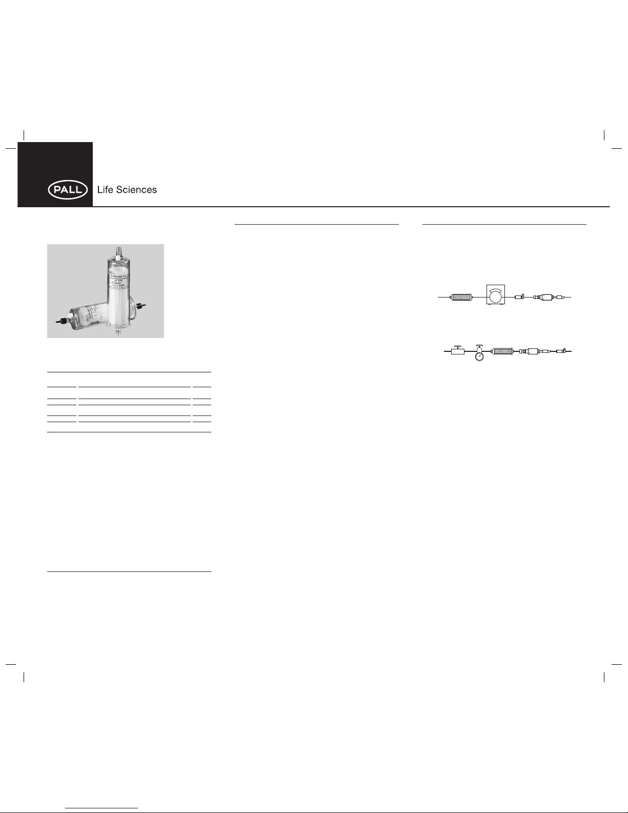
Envirochek® and Envirochek HV
Sampling Capsules
• Designed for the concentration and recovery of Cryptosporidium sp. oocysts
and Giardia sp. cysts.
• Envirochek HV capsule optimized for sampling high volumes of source or
treated water.
Ordering Information
Part Number Description Pkg
12098 Envirochek HV sampling capsule, bulk pack, 25/cs
individually bagged
12099 Envirochek HV sampling capsule 1/pkg
12107 Envirochek sampling capsule, bulk pack, 25/cs
individually bagged
12110 Envirochek sampling capsule 1/pkg
Specifications
Materials of Construction
Filter Media
12107, 12110: Supor
®
(polyethersulfone) membrane
12098, 12099: Polyester
Housing: Polycarbonate
End Caps: Vinyl
Filter Support Material: Polypropylene
Pore Size
1.0 μm
Effective Filtration Area
1300 cm
2
Dimensions
Length: 21 cm (8.5 in.)
Diameter: 6 cm (2.4 in.)
Inlet/Outlet Connections
12.7 mm (1/2 in.) straight hose barb
Maximum Operation Pressure
6.9 bar (690 kPa, 100 psi)
Maximum Differential Pressure
12107, 12110: 2.1 bar (210 kPa, 30 psid) at 21 ºC (70 ºF)
12098, 12099: 4.1 bar (410 kPa, 60 psid) at 21 ºC (70 ºF)
Sterilization
Provided non-sterile
Instructions for Use
This method does not address all of the safety concerns that are associated with
pathogen concentration and testing. It is the responsibility of the user of this device
and method to determine and employ all applicable safety measures to ensure the
safety of themselves and others. Check for regulatory limitations that may apply
prior to using this device.
Proper assembly and flow direction is critical to the filter’s performance. Improper
assembly can result in decreased throughput, lower sediment recoveries and, in
extreme cases, damage to the pleated membrane within the device.
Instructions for Use (continued)
1.0 Materials
1.1 Envirochek or Envirochek HV sampling capsule, one capsule per
sample. The capsules are not reusable.
1.2 Hose-type tubing, 12.7 mm (0.5 in.) I.D.
1.3 Clamps
1.4 Water meter (flow totalizer)
1.5 Flow control valve or flow rate meter with valve
1.6 Pump, electric or gasoline powered (if needed)
1.7 Laboratory Shaker (Pall Life Sciences PN 4821A, 115V; 4822A, 230V)
1.8 Ice chest or cooler with cold packs
1.9 250 mL conical centrifuge tubes
1.10 50 mL polypropylene tubes
1.11 Elution Buffer
1.11.1 10 mL Laureth-12 solution (see below)
1.11.2 10 mL 1 M Tris, pH 7.4 (see below)
1.11.3
02 mL 0.5 M Ethylenediamine Tetraacetic Acid (EDTA),
2 Na, pH 8.0 (see below)
1.11.4 150 μL Antifoam A
1.11.5 5% w/v of Sodium Hexamethaphosphate (NaHMP) solution
(see below)*
1.11.6 Preparation of Laureth-12 Solution
Weigh 10 g of Laureth-12 (PN 4820) and dissolve in 90 mL
of reagent water using a microwave or hot plate. Dispense in
10 mL aliquots into sterile vials and store at room temperature
for up to 2 months or in a freezer for up to a year.
1.11.7 Preparation of 1 M Tris, pH 7.4
Dissolve 121.1 g Tris in 700 mL reagent water and adjust
pH to 7.4 using 1 N HCl or NaOH. Dilute to a final volume of
1000 mL with reagent water and adjust the final pH. Filtersterilize through a 0.2 μm membrane (PN 4632) into a sterile
plastic container and store at room temperature.
1.11.8 Preparation of 0.5 M EDTA, 2 Na, pH 8.0
Dissolve 186.1 g EDTA, sodiumdihydrate in 800 mL reagent
water and adjust to pH 8.0 using 6 N HCl or NaOH. Dilute to
a final volume of 1000 mL with reagent water and adjust the
final pH using 1 N HCl or NaOH.
1.11.9 Preparation of 5% w/v Sodium Hexametaphosphate Solution
Dissolve 50 g of sodium hexametaphosphate (NaPO
3)n
in
600 mL of reagent water. Dilute to final volume of 1000 mL
using reagent water. Store in a plastic or glass container at
room temperature for up to 3 months. Discard when expiration
date is reached or sooner if microbial growth is apparent.
1.11.10 Preparation of Buffer Solution
• Add the contents of a 10 mL vial of Laureth-12 solution to a
1000 mL graduated cylinder. Rinse the vial several times to
ensure the complete transfer of detergent.
• Add 10 mL Tris solution, pH 7.4; 2 mL EDTA solution, pH 8.0;
and 150 μL Antifoam A to the graduated cylinder.
• Bring solution to a final volume of 1000 mL with reagent
water. The buffer will have an opaque appearance.
Instructions for Use (continued)
2.0 Sample Collection
2.1 Retain the vinyl caps provided with the sampling capsule for sample
shipping and the elution process.
2.2 The exact installation is dependent on whether or not the water is from
a pressurized water source. If the source is not pressurized, a pump is
required. If a pump is required, the system will appear as in Figure 1a.
If a pump is not required, the system will appear as in Figure 1b.
Figure 1a: Sampling system with pump
Figure 1b: Sampling system without pump
2.3 Before connecting the sampling system to the pressurized system
or sample source, turn the pressurized system or pump on, allowing
water to purge residual debris from the water lines for 2-3 minutes, or
until the turbidity becomes uniform.
2.4 Turn off the pressurized source or pump and connect the sampling
system without the sampling capsule.
2.5 Turn on the pressurized source or pump and adjust the flow rate as
recommended by the current approved method for your region.
2.6 Allow approximately 2-10 L source or reagent water to flush the
system.
2.7 Install the sampling capsule in line, securing the inlet and outlet ends
with the appropriate fittings/clamps.
2.8 With a water-resistant marking pen, record the sampling location,
name of the person performing the sampling, date, meter reading, and
turbidity of the sample on the label provided on the filter housing.
2.9 Initiate water flow.
2.10 Vent the residual air in the capsule using the vent valve by turning it in
a counter clockwise direction. When the filter housing is full of water,
quickly close the vent valve.
2.11 After you have collected your sample through the sampling capsule,
shut off your water source. Allow the pressure to decay until flow stops.
2.12 Record the stop time and final meter reading in the appropriate spaces
on the label on the filter.
2.13 Disconnect the inlet end of the sampling capsule, making sure not to
spill any of the water remaining in the capsule. This water is part of
your sample.
2.14 Seal the inlet of the capsule with the vinyl end cap that was saved from
step 2.1.
2.15 Loosen the outlet end and allow water to drain as much as possible.
Water drainage from the capsule through the outlet is acceptable since
the sample has passed through the membrane.
2.16 Seal the outlet of the capsule with the vinyl end cap that was saved
from step 2.1.
2.17 Transport sampling capsules to testing facility according to
temperature and hold time requirements listed in current approved
method for your region.
Envirochek
Sampling
Capsule
Flow Totalizer
(meter)
Flow
Restrictor
Waste
Pump
Water
Source
Pressure
Regulator
Envirochek
Sampling
Capsule
Flow Totalizer
(meter)
Flow
Restrictor
Waste
Open/Close
Valve
Pressurized
Water
Source
*Note: Use of NaHMP is accepted by EPA Method 1623.1 for the improved
recovery of cysts and oocysts in certain water matrices. If you elect to use this
step, this must be performed on all OPR’s and the same lot of elution buffer.
1401_87997D.indd 11401_87997D.indd 1 8/27/14 10:32 PM8/27/14 10:32 PM
Page 2

Instructions for Use (continued)
3.0 Elution Method
3.1 Assemble the Laboratory Shaker with the arms at full extension and
the clamps aligned in a vertical position so the capsules will be aligned
horizontally, as demonstrated in Figure 2.
Figure 2: Proper assembly of Laboratory Shaker
3.2a *Dispersant Addition
3.2a.1 Record the elution date and time on the bench sheet. Using
a ring stand or other means, clamp each capsule in a vertical
position with the inlet end up.
Note: Dispersant Addition cannot be performed on a sampling capsule
through which water can no longer be filtered (i.e. clogged). Record on
the bench sheet that the sampling capsule is clogged, and proceed to
Elution Method.
3.2a.2 Remove the inlet cap, pour NaHMP solution through the inlet
opening, and allow the liquid level to stabilize. Sufficient NaHMP
solution must be added to cover the pleated white membrane
with NaHMP solution or NaHMP solution may be measured to
125 mL. Replace the inlet cap.
3.2a.3 Securely clamp the capsule in one of the clamps on the
laboratory shaker with the bleed valve positioned at the top on a
vertical axis (in the 12 o’clock position). Turn on the shaker and
set the speed to maximum (700-900 rpm or per manufacturer’s
instructions). Agitate the capsule for approximately 5 minutes.
Time the agitation using a lab timer, rather than the timer on the
shaker to ensure accurate time measurement.
3.2a.4 Remove the filter from the shaker, remove the outlet cap, and
attach the capsule filter outlet to tubing, upstream of a pump.
Holding the filter upright, remove the inlet cap, being careful not
to pour any liquid from the inlet, turn on the pump and allow
pump to pull all the NaHMP through the filter, turn off pump. Do
not allow the filter pleats to collapse during the pumping process.
3.2a.5 Fill the capsule with reagent water, pinching the outlet hose
if necessary, to cover the white pleated membrane and the
plastic above the membrane; allow the liquid level to stabilize.
Sufficient reagent water must be added to cover the pleated
white membrane. Turn on the pump and allow pump to pull all
the water through the filter. Turn off the pump.
3.2a.6 Replace the inlet cap. Disconnect the outlet tubing from the
filter, and replace the outlet cap. Proceed directly to elution
within the same working day.
3.2 Prepare sufficient elution buffer so all the samples to be eluted that day
can be eluted with the same stock elution buffer solution. (see 1.11)
3.3 Designate a 250 mL conical centrifuge tube for each sample and label
with the sample number.
3.4 If the upper chamber of the capsule has water remaining in it, pull the
remaining fluid through the filter before eluting the filter.
3.5 Hold the capsule in a vertical position with the inlet end up by using a
ring stand or other means. Remove the vinyl end cap.
If eluting standard volumes of source water, proceed to step 3.6, If
eluting high volumes of drinking water continue with step 3.5.1:
3.5.1 Fill the sampling capsule with a 5% weight by volume of sodium
hexametaphosphate in reagent water.
3.5.2 Replace the vinyl end cap on the inlet and securely clamp the
sampling capsule on the laboratory shaker.
3.5.3 Turn on the shaker, set the speed at approximately 600 rpm,
and agitate for 5 minutes.
3.5.4 Turn off the shaker, remove the sampling capsule, hold upright
and remove the vinyl end cap from the outlet.
3.5.5 Loosen the vent valve and allow the sodium hexametaphosphate
solution to drain through the capsule membrane and out the outlet.
3.5.6 Tighten the vent valve and replace the vinyl end cap on the outlet
of the sampling capsule.
Instructions for Use (continued)
3.5.7 Hold the capsule in the vertical position with the inlet end up by
using a ring stand or other means. Remove the vinyl end cap
from the inlet.
3.5.8 Repeat steps 3.5.1 through 3.5.7 using reagent water.
3.6 Add elution buffer to the inlet end of the capsule and allow liquid level
to stabilize. Sufficient elution buffer should be added to the capsule to
ensure the covering of the pleated white filter module by approximately
13 mm (0.5 in.) (see Figure 3). Replace the vinyl end cap to the inlet
end of the capsule.
Figure 3: Elution buffer level
3.7 Securely clamp the capsule on the Laboratory Shaker so the vent valve
is facing toward you. Make sure the vent valve is in the 12 o’clock
position (see Figure 4).
3.8 Turn on the shaker and set the speed at approximately 600 rpm and
agitate for 5 minutes.
3.9 Remove the sampling capsule from the shaker. Carefully remove the
inlet end cap and decant the contents of the capsule into a 250 mL
conical centrifuge tube.
3.10 Add new elution buffer to the inlet end of the capsule and allow liquid
level to stabilize. Sufficient elution buffer should be added to the
capsule to ensure the covering of the pleated white filter module by
approximately 13 mm (0.5 in.) (see Figure 3). Replace the vinyl end cap
to the inlet end of the capsule.
3.11 Again, securely clamp the capsule on the Laboratory Shaker so the vent
valve is facing toward you. This time make sure the vent valve is in the
4 o’clock position (see Figure 4).
3.12 Turn on the shaker and set the speed at approximately 600 rpm and
agitate for 5 minutes.
3.13 Turn off the shaker and loosen the clamp but do not remove the
capsule and decant the elution buffer.
3.14 Rotate the capsule until the vent valve is in the 8 o’clock position
(see Figure 4), secure the capsule in place, and agitate at 600 rpm for
5 minutes.
3.15 As in step 3.9, remove the capsule from the shaker, carefully remove
the inlet end cap and decant the contents of the capsule into the same
250 mL conical centrifuge tube labeled for that sample.
Figure 4: Orientation of sampling capsules during elution
Fill to this level
with elution buffer.
1.0 m Sampling Capsule
PN. 12099
Pall Corporation
Vent Valve Vent Valve Vent Valve
First Cycle Second Cycle Third Cycle
12 o’clock position 4 o’clock position 8 o’clock position
International OfÄ ces
Pall Corporation has ofÄ ces and plants throughout the world in; Argentina, Australia, Austria, Belgium, Brazil, Canada,
China, France, Germany, India, Indonesia, Ireland, Italy, Japan, Korea, Malaysia, New Zealand, Norway, Philippines,
Poland, Russia, Singapore, South Africa, Spain, Sweden, Switzerland, Taiwan, Thailand, United Kingdom, and
Vietnam. Distributors in all major industrial areas of the world. To locate the Pall ofÄ ce or distributor nearest you, visit
www.pall.com/contact.
The information provided in this literature was reviewed for accuracy at the time of publication. Product data may be
subject to change without notice. For current information consult your local Pall distributor or contact Pall directly.
Visit us on the Web at www.pall.com/lab
E-mail us at LabCustomerSupport@pall.com
Pall Life Sciences
25 Harbor Park Drive
Port Washington, NY 11050 USA
Instructions for Use (continued)
4.0 Concentration: Adjustment of Pellet Volume
4.1 Spin the sample at 1500 x G for 15 minutes. Allow the centrifuge to
coast to a stop. DO NOT USE THE BRAKE!
4.2 Record the volume of the pellet with date and time the concentration
was completed. Use a Pasteur pipette to carefully remove the
supernatant to 5 mL above the pellet. Refer to current approved
method for instructions on pellet analysis.
5.0 Detection
5.1 The sample is now ready for the detection stage of the process. Refer
to the current approved detection method for your region.
WARNING
Employment of the products in applications not specified, or failure to follow
all instructions contained in this product information insert, may result in
improper functioning of the product, personal injury, or damage to property
or the product. See Statement of Warranty in our most recent catalog.
This method is in accordance with EPA Method 1622: Cryptosporidium in
Water by Filtration; & EPA Method 1623 & 1623.1: Cryptosporidium and
Giardia in Water by Filtration; however, consult your local regulations to
ensure compliance.
Go to www.pall.com/lab for these instructions translated into multiple languages.
© 2014, Pall Corporation. Pall, , Envirochek, and Supor are trademarks of Pall Corporation. ® indicates a
trademark registered in the USA.
09/14 PN 87997D
1401_87997D.indd 21401_87997D.indd 2 8/27/14 10:32 PM8/27/14 10:32 PM
 Loading...