

Page 1
User Guide
Cadence
™
Inline Concentrator
with Delta and Omega
™
Membranes
Care and Use Procedures
USD 2841c
Page 2

2
Contents
1. Important Information ...............................................................................................................................3
1.1 Safety Notice ........................................................................................................................................3
1.2 Application of the Care and Use Procedures .......................................................................................4
1.3 Using the Cadence Inline Concentrator (ILC) Module Safely ................................................................4
1.4 Locating Safety Information ..................................................................................................................5
1.5 Environmental Compliance ...................................................................................................................5
1.6 Where to Get Help ...............................................................................................................................5
2. Learning about the Cadence Inline Concentrator Module ....................................................................6
2.1 Cadence ILC Module ...........................................................................................................................6
2.2 Cadence ILC Module Information .........................................................................................................6
2.3 Cadence ILC Module Port Locations....................................................................................................6
3. Application of Single-Pass Tangential Flow Filtration.............................................................................7
3.1 Process Variables .................................................................................................................................7
3.2 Proper Use...........................................................................................................................................7
4. An Overview of Cadence ILC Processing ...............................................................................................7
4.1 The Four Parts of a Single-Pass TFF Process ......................................................................................7
5. Using the Cadence ILC Module ...............................................................................................................9
5.1 Preparation: Equipment and Materials..................................................................................................9
5.2 Part 1 — Pre-Use Conditioning ..........................................................................................................10
Procedure A — Connect the Cadence ILC Module to the Tubing ......................................................10
Procedure B — Flush the Cadence ILC Module with Purified Water ..................................................10
Procedure C — Sanitize the Cadence ILC Module ............................................................................11
Procedure D — Flush the Cadence ILC Module with Purified Water ..................................................11
Procedure E — Determine Cadence ILC Module Normalized Water Permeability (NWP) ....................12
Procedure F — Determine the Hold-Up Volume of the Cadence Setup and Module ..........................13
Procedure G — Test the Integrity of the Cadence ILC Module ..........................................................14
Procedure H — Flush with Buffer ......................................................................................................15
5.3 Part 2 — Processing ..........................................................................................................................15
Procedure I — Process Product ........................................................................................................15
Procedure J — Recover Product from the Cadence ILC Module........................................................15
5.4 Part 3 — Post-Use Conditioning ........................................................................................................16
Procedure K — Clean the Cadence ILC Module ................................................................................16
Procedure L — Flush the Cadence ILC Module with Purified Water ...................................................17
Procedure M — Determine Cadence ILC Module Normalized Water Permeability (NWP) ...................17
Procedure N — Test Integrity of the Cadence ILC Module .................................................................17
Procedure O — Add Storage Solution to the Cadence ILC Module ...................................................17
5.5 Part 4 — Post-Use Disposal ..............................................................................................................18
6. Appendices ..............................................................................................................................................18
6.1 Recommended Storage of New Cadence ILC Modules .....................................................................18
6.2 Delta and Omega Membranes Chemical Compatibility .......................................................................18
6.3 Alternative Chemical Agents ..............................................................................................................18
Page 3
3www.pall.com/biotech
1. Important Information
1.1 Safety Notice
WARNING! Do not pressurize module over 4.1 barg (60 psig).
Important Notice
Refer to safety instructions before use.
Safety instructions in this language are
available from Pall.
Viktigt att notera
Läs säkerhetsinstruktionerna före
användandet.
Säkerhetsinstruktioner på svenska finns
att få frän Pall.
Viktig melding
Les Sikkerhetsinstruksjonen før bruk.
Sikkerhetsintruksjon på norsk vil være
tilgjengelig fra Pall.
Belangrijke informatie:
Voor gebruik veiligheidsinstructies goed
doornemen.
Veiligheids instructies in het
Nederlands zijn bij Pall verkrijgbaar.
Avvertenza importante
Prima dell’uso leggere le istruzioni
per la sicurezza.
Le istruzioni per la sicurezza in
Italiano possono essere richieste
a Pall.
Important
Se référer aux instructions
concernant la sécurité d’utilisation avant
usage.
Les instructions concernant la
sécurité d’utilisation sont disponibles en
français chez Pall.
Vigtigt
Læs sikkerhedsinstruktioner før
ibrugtagning.
Sikkerhedsinstruktioner på dansk
kan fås fra Pall.
Tärkeä tiedote
Lue turvallisuusohjeet ennen käyttöä.
Pall toimittaa tarvittaessa suomenkieliset
turvallisuusohjeet.
Wichtige Anmerkung
Vor Gebrauch bitte die
Sicherheitsrichtlinien lesen. Die
Sicherheitsrichtlinien in dieser Sprache
erhalten Sie von Pall.
Aviso importante
Antes de utilzar, consultar instruçöes de
segurança.
Instruçöes de segurança em Português,
encontram-se disponiveis na Pall.
Aviso importante
Antes de usar, consultar Instrucciones de
Seguridad.
Instrucciones de Seguridad en este
idioma están disponibles por Pall.
Page 4
4
1.2 Application of the Care and Use Procedures
This guide describes the care and use of Cadence Inline Concentrator (ILC) modules with
Delta and Omega 10 kDa and 30 kDa membranes. Do not apply these procedures to Pall’s
conventional tangential flow filtration (TFF) cassettes or Cadence single-pass TFF (SPTFF)
standard modules.
The care and use procedures described in this document apply to the products listed in Table 1:
Table 1
Cadence ILC module part numbers
Cadence ILC Module Part Number
Delta Membrane Omega Membrane MWCO* (kDa) Cassette Format
Membrane Area (m2)
ILD010T010407 ILOS010T010407 10 T01 0.065
ILD010T020407 ILOS010T020407 T02 0.13
ILD010T120407 ILOS010T120407 T12 0.7
ILD010T060407 ILOS010T060407 T06 3.5
ILD030T010407 ILOS030T010407 30 T01 0.065
ILD030T020407 ILOS030T020407 T02 0.13
ILD030T120407 ILOS030T120407 T12 0.7
ILD030T060407 ILOS030T060407 T06 3.5
* Molecular weight cut-off
1.3 Using the Cadence Inline Concentrator Module Safely
Read all safety warnings and operating instructions before using the Cadence ILC module.
Keep this care and use guide in an accessible location and make it available to users of the
Cadence ILC modules. General safety precautions include:
• Wear the appropriate personal protective equipment (PPE) and clothing including safety
glasses and gloves when working with Cadence ILC modules, systems, and chemical
solutions.
• The solutions recommended for sanitization may be hazardous or corrosive. Refer to the
Material Safety Data Sheets (available from the chemical suppliers) to learn how to use
the recommended solutions safely.
• Do not exceed the operating limits of the Cadence ILC module or process components.
• Provide sufficient space around the Cadence ILC module to work ergonomically and safely
when assembling and using the module.
• Disconnecting or dismantling Cadence ILC module components without first isolating and
depressurizing the system or setup can lead to injury from the uncontrolled release of high
pressure air and solutions. Depressurize the Cadence ILC module before dismantling
components.
• Some system components may be heavy. Take proper precautions when moving or lifting
equipment to prevent personal injury. Hoists or other lifting equipment may be needed to
assemble some Cadence product equipment.
• Wipe up spills promptly to prevent injury from contact or slipping.
Page 5

www.pall.com/biotech 5
1.4 Locating Safety Information
This care and use guide presents safety information as follows:
HELPFUL INFORMATION!
Communicates important and helpful information about the current topic.
CAUTION!
Identifies safety risks that could cause personal injury, or situations that may cause
product damage.
WARNING!
Identifies safety risks that can cause serious personal injury, or situations that may cause
irreversible damage to equipment.
1.5 Environmental Compliance
Users should dispose of storage and by-product solutions according to local, state, and
federal regulations.
1.6 Where to Get Help
If you do not understand the information in this guide, or need additional assistance in using
Cadence ILC modules, contact Pall. Pall provides these additional resources to help make your
experience with our products trouble-free:
Materials Safety Data Sheets — Offer safety information about the chemicals used to store
Cadence ILC modules, and are available online at www.pall.com/procedures.
Support Services — The Pall Biotech customer support team can answer technical questions
and provide replacement parts.
Pall operates a technical service to assist in the application of our products. This service is
readily available to you and welcome your questions so that we can help. In addition, an
extensive network of technical representatives is available throughout the world. For additional
questions or technical assistance, you may contact BTASC@pall.com.
Web Site (http://www.pall.com/biotech) — Provides contact information for Pall Biotech
offices throughout the world.
Page 6
6
2. Learning about the Cadence Inline Concentrator Module
2.1 Cadence ILC Module
The Cadence Inline Concentrator (ILC) is a self-contained, single-pass TFF module that
simplifies TFF for volume reduction and continuous concentration applications. This plug-andplay module, comprised of membrane cassettes, gaskets and manifold plates enclosed
between two end plates, eliminates the need for a holder and requires only a pressure source
for operation.
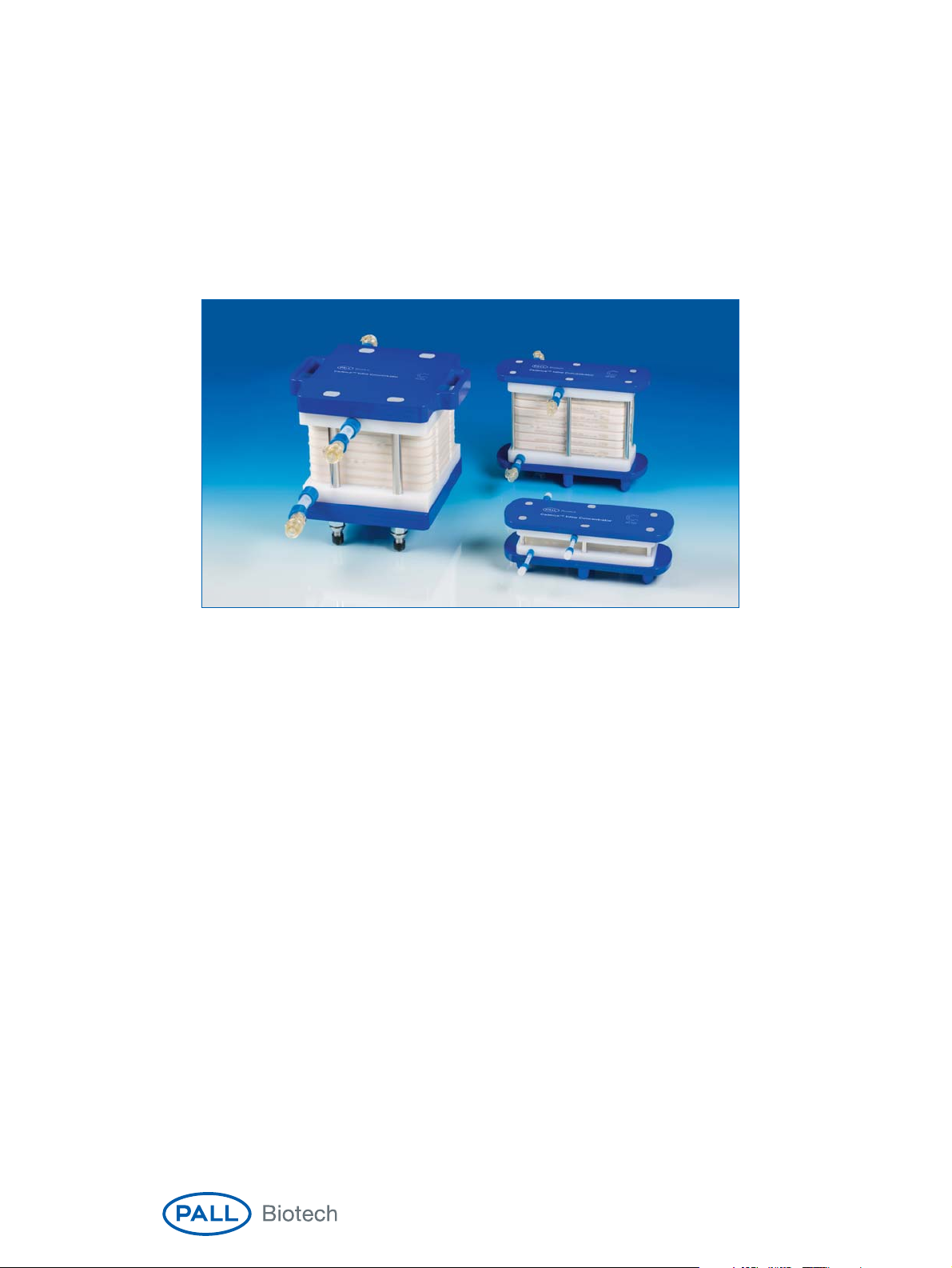
Figure 1
Cadence Inline Concentrator T06 (3.5 m2) , T12 (0.7 m2), and T01 (0.065 m2) formats
2.2 Cadence ILC Module Information
Inscription on each Cadence ILC module includes the following information:
• Company logo and name
• Product name
• Part number
• Serial number
• Port labels
• Product pressure rating
• Pall patent website address
• Membrane type
• Total membrane area
2.3 Cadence ILC Module Port Locations
Cadence ILC modules have feed, retentate, and two permeate ports. Ports on the Cadence
T01 and T02 modules use female Luer lock connectors. The ports on the Cadence T12
modules use female MPC quick disconnect connectors. A label located next to each port
identifies the port’s function. The ports on the Cadence T06 modules use female MPX quick
disconnect connectors.
Page 7

www.pall.com/biotech 7
Figure 2
Cadence Inline Concentrator T12 module port locations
Permeate 2 port
Permeate 1 port
Retentate port
Feed port
3. Application of Single-Pass Tangential Flow Filtration
Single-pass tangential flow filtration is a patented novel technology that enables the concentration
of process solutions with the simplicity of direct flow filtration, and can be used for:
• Continuous product concentration
• In-process volume reduction
• In-process salt reduction
• Processing of fragile biomolecules
Depending upon the format size of the Cadence ILC module, product volumes of several hundred
liters can be processed. The modules can be coupled (before or after) to other process steps
(e.g., chromatography).
3.1 Process Variables
Optimum processing conditions and sizing for the Cadence ILC module may need to be
determined via trials, considering the following processing variables:
• Product characteristics (i.e., concentration, viscosity, temperature, and shear sensitivity)
• Concentration factor ranges
• Feed pressure or feed flow rate
Process control with the Cadence ILC module can be easily achieved by setting either the
feed pressure or feed flow rate to reach processing targets. Please contact Pall for single-use
Allegro™ systems or assemblies to operate the Cadence ILC module.
3.2 Proper Use
The following chapters describe the procedures to properly install and prepare Cadence ILC
modules. You may need to modify some aspects of the procedures to fit your specific
objectives.
4. An Overview of Cadence ILC Processing
4.1 The Four Parts of a Single-Pass TFF Process
The SPTFF process can be divided into four parts:
• Part 1 — The first part involves connecting the Cadence ILC module and preparing it for use.
This part (called pre-use conditioning) involves several sequential steps.
• Part 2 — The second part (called processing) involves using the Cadence ILC module to
meet the filtration objectives. Processing includes product filtration and product recovery.
Page 8

8
• Part 3 — The third part (called post-use conditioning) includes cleaning, testing and storage
of the Cadence ILC module. This part is optional and is applicable only when the module
is reused.
• Part 4 — The fourth part includes proper disposal of the Cadence ILC module.
An illustration summarizes the four parts of an SPTFF process and provides a map for learning
the procedures in each part (Figure 3).
HELPFUL INFORMATION!
It may be helpful to photocopy Figure 3 and use it as a reference
until you learn the procedures used in each part of the SPTFF process.
WARNING!
The Cadence ILC module is a disposable device. It could potentially be used
several times. However, specific end-user studies should be conducted to identify the limited
re-use range and validate specific re-use requirements per application.
Figure 3
Main parts of a Cadence ILC process and the procedures required to complete each part
12 43
Pre-Use
Conditioning
A
Connect Cadence
Module
B
Remove Air,
Flush with Water
C
Sanitize Cadence
Module
Processing
I
Process Product
J
Recover Product
Post-Use
Conditioning
(Optional)
K
Clean Cadence
Module
L
Flush with Water
M
Determine
Permeability
Post-Use
Disposal
Proper Disposal
of Module
D
Flush with Water
E
Determine
Permeability (Optional)
F
Determine
Hold-Up Volume
G
Integrity Test
H
Remove Air,
Flush with Buffer
N
Integrity Test
O
Add Storage
Solution
Page 9

www.pall.com/biotech 9
5. Using the Cadence ILC Module
This section describes how to complete the procedures in each of the four parts of an SPTFF process,
and is organized as follows:
• Preparation of Equipment and Materials
• Part 1 — Pre-Use Conditioning: Procedures A through H
Pre-use conditioning establishes the fitness of the module for use.
• Part 2 — Processing: Procedures I through J
• Part 3 — Post-Use Conditioning (optional): Procedures K to O
• Part 4 — Post-Use Disposal
5.1 Preparation: Equipment and Materials
Equipment
• Cadence ILC module
• SPTFF set-up consisting of (at minimum) a feed pressure source and feed pressure sensor,
and a permeate 1 pressure sensor. Typically, end-users also have retentate and/or permeate
flowmeters (or scales) to monitor their process.
• Appropriate tubing set. Pall can provide tubing sets for your application, please contact your
Pall representative for more details
• Containers to hold and collect product, water, buffer, and sanitizing solutions
• Tubing and connectors:
– For a Cadence system with Cadence T01 or T02 modules: Female Luer type connectors
and ⅛ in. internal diameter (ID), that needs to withstand 4.1 barg (60 psig)
– For a Cadence system with Cadence T12 modules: MPC quick disconnect fittings,
¼ in. ID, that needs to withstand 4.1 barg (60 psig)
– For a Cadence system with Cadence T06 modules: MPX quick disconnect fittings,
½ in. ID, that needs to withstand 4.1 barg (60 psig)
• Personal protective equipment as required by OSHA (U.S. Occupational Safety and Health
Administration) and your facility’s safety regulations
• pH meter
• Palltronic
®
Flowstar integrity test instrument
• Thermometer
Materials
• Product solution
• Buffer solution compatible with product: 15 L/m
2
• De-ionized, 0.2 μm filtered water: 40 L/m2(for pre-conditioning steps)
• Sodium hydroxide: 45 L/m
2
(for pre-conditioning sanitization)
– Delta membranes: 0.1 – 0.25 N
– Omega membranes: 0.1 – 0.5 N
• FOR REUSE: Post-conditioning cleaning agent, 50 L/m
2
– Delta membranes: 0.1 N sodium hydroxide
– Omega membranes: 0.5 N sodium hydroxide + 400 ppm sodium hypochlorite
• FOR REUSE: Storage solution, 10 L/m
2
– Delta membranes: 0.1 N sodium hydroxide (< 3 months); 5% ethanol, 1% sodium
diacetate (> 3 months)
– Omega membranes: 0.1 N sodium hydroxide
HELPFUL INFORMATION:
Solution volumes are provided as a guide. Appropriate volumes
must be determined by users for their specific applications.
Page 10

10
Note on Water Quality
For the purposes of SPTFF, the term purified water refers to de-ionized, 0.2 µm filtered water.
Using unfiltered water can foul the membrane in the Cadence ILC module.
5.2 Part 1 — Pre-Use Conditioning
u
Procedure A — Connect the Cadence ILC Module to the Tubing
CAUTION!
All equipment (pump, pressure can, etc.) and plumbing upstream of the Cadence
ILC module must be sanitized and flushed prior to connecting to the module.
Prepare to use the Cadence ILC module following these steps:
1. Wearing protective gloves and safety glasses, open the Cadence ILC module bag and
remove module from bag.
2. Remove the caps from the ports.
3. Connect tubing to appropriate module ports.
HELPFUL INFORMATION!
Cadence ILC modules are operated without a holder. The module
must always rest on its bottom feet and never on its side to avoid damage to the ports.
CAUTION!
Do not exceed a feed pressure of 4.1 barg (60 psig) at 20 – 40 °C during any
pre-use, processing, or post-use procedures. Exceeding 4.1 barg (60 psig) of feed pressure
can permanently damage the Cadence ILC module or lead to product leakage. Do not exceed
a feed pressure of 1.5 barg (22 psig) when the permeates are fully closed. Additionally, do not
exceed the pressure rating of the tubing during operation or integrity testing. Tubing that is
rated to at least 4.1 bar (60 psi) should be used.
u
Procedure B — Flush the Cadence ILC Module with Purified Water
Cadence ILC modules are stored in a solution containing:
– Delta membranes: 5% ethanol and 1% sodium diacetate
– Omega membranes: 0.3 N sodium hydroxide
Figure 4
Cadence ILC module (T12 format) with tubing set (tubing set sold separately)
Page 11

Flush the storage solution from the Cadence ILC module following these steps:
1. Direct permeate and retentate lines to drain.
2. Fully open the feed, retentate, and permeate 2 lines, and close the permeate 1 line.
3. Start the feed pump and slowly increase the pump speed until the feed pressure reaches
1.4 – 2.8 barg (20 – 40 psig).
4. Open the permeate 1 line for 1 minute to ensure that the lines are flooded and then close.
5. Subsequently, every 5 minutes, open the permeate 1 line for 30 seconds.
6. Stop the feed pump once 20 L/m
2
of purified water has passed through the module or when
the pH reaches ≤7.
HELPFUL INFORMATION!
The effectiveness of this flushing protocol will depend on the
composition and volume of chemicals in the module, and minimum acceptable levels in effluent
at the end of the flush. The user must evaluate and validate the effectiveness of the process with
respect to time, temperature and other operating conditions.
HELPFUL INFORMATION!
It is important to remove entrapped air during flushing. If excessive
air is observed exiting the module, increasing feed pressure (maximum of 4.1 barg or 60 psig)
and flow rates will assist in the air removal method. Slight adjustments to the protocol may be
necessary to optimize this step. However, do not exceed the pressure rating of the tubing used.
u
Procedure C — Sanitize the Cadence ILC Module
Sanitize the Cadence ILC module following these steps:
1. Connect the feed line to a supply of sanitization solution (see Section 5.1) at ambient
temperature.
2. Direct permeate and retentate lines to drain.
3. Fully open the feed, retentate, and permeate 2 lines, and close the permeate 1 line.
4. Start the feed pump and slowly increase the pump speed until the feed pressure reaches
1.4 – 2.8 barg (20 – 40 psig).
5. Open the permeate 1 line for 1 minute, and close for the remainder of the sanitization step.
6. Stop the feed pump after 45 L/m
2
of sanitization solution has passed through the module.
HELPFUL INFORMATION!
The effectiveness of this sanitization protocol conducted in
single-pass mode, to reduce or eliminate bioburden, depends on the nature and level of the
contamination. The user must evaluate and validate the effectiveness of the process with
respect to time, temperature, sanitization agent, and other operating conditions.
u
Procedure D — Flush the Cadence ILC Module with Purified Water
Flush the sanitization solution from the Cadence ILC module with purified water following
these steps:
1. Connect the feed line to a supply of purified water.
2. Direct permeate and retentate lines to drain.
3. Fully open the feed, retentate, and permeate 2 lines, and close the permeate 1 line.
4. Start the feed pump and slowly increase the pump speed until the feed pressure reaches
1.4 – 2.8 barg (20 – 40 psig).
5. Open the permeate 1 line for 1 minute to ensure that the lines are flooded and then close.
6. Subsequently, every 5 minutes, open the permeate 1 line for 30 seconds.
7. Stop the feed pump once 20 L/m
2
of purified water has passed through the module or when
the pH reaches ≤7.
www.pall.com/biotech 11
Page 12

12
HELPFUL INFORMATION!
The effectiveness of this flushing protocol will depend on the
composition and volume of chemicals in the module, and minimum acceptable levels in effluent
at the end of the flush. The user must evaluate and validate the effectiveness of the process
with respect to time, temperature and other operating conditions.
u
Procedure E — Determine Cadence ILC Module Normalized Water
Permeability (NWP)
If a new or previously used and stored Cadence ILC module is used, the user will need to
measure the permeability of the module before use. Later, after using and cleaning the module,
the NWP of the module should be measured again. By comparing the NWP before and after
use, the user can determine the effectiveness of the cleaning method and also determine when
the module reaches the end of its service life.
Follow these steps to measure the module’s NWP:
1. Connect the feed line to a supply of purified water.
2. Fully open the feed and permeate 2 lines. Close retentate and permeate 1 lines.
3. Direct the permeate line to drain. If applicable, quickly open and close the retentate valve
a few times to expel any trapped air.
4. Adjust the feed pump and increase the pump speed to deliver a feed pressure value of
1 barg (15 psig) and measure/record the corresponding permeate flow rate.
5. Record the temperature of the permeate stream.
6. Stop the feed pump.
Normalize the permeate flux to 20 °C following these steps:
1. Using the permeate flow rate measurements from step #4 above, calculate the permeate flux
in units of L/m
2
/hr (LMH).
2. Using temperature correction factors (Table 2), normalize the permeate flux to 20 °C
(Equation 1).
Equation 1
Permeate flux normalized to 20 °C
3. Using the feed, retentate, and permeate 1 pressures obtained while measuring Cadence ILC
module permeability, calculate the apparent transmembrane pressure (Equation 2).
Note: Permeate 2 is open to atmosphere. For simplicity, the feed and the retentate pressures
are assumed equivalent in the dead-end method. This approximation requires a minimum
system setup with two pressure sensors on feed and permeate 1 lines.
Equation 2
Transmembrane pressure (TMP) calculation
4. Determine the apparent NWP dividing the permeate water flux at 20 °C by the
transmembrane pressure. The NWP is expressed in units of LMH/barg or LMH/psig units.
Flux at 20 °C = Permeate Flux x TCF
20 °C
TMP =
(
P
Feed
+ P
Retentate
)–(
P
Permeate 1
+ P
Permeate 2
)
22
Page 13

www.pall.com/biotech 13
Table 2
Temperature correction factors (TCF
20 °C
) for Cadence ILC module permeability
T °C TCF
20 °C
T °C TCF
20 °C
4 1.57 28 0.83
5 1.52 29 0.81
6 1.47 30 0.80
7 1.43 31 0.78
8 1.39 32 0.76
9 1.35 33 0.75
10 1.31 34 0.73
11 1.27 35 0.72
12 1.24 36 0.70
13 1.20 37 0.69
14 1.17 38 0.68
15 1.14 39 0.66
16 1.11 40 0.65
17 1.08 41 0.64
18 1.05 42 0.63
19 1.03 43 0.62
20 1.00 44 0.61
21 0.98 45 0.60
22 0.95 46 0.59
23 0.93 47 0.58
24 0.91 48 0.57
25 0.89 49 0.56
26 0.87 50 0.55
27 0.85
u
Procedure F — Determine the Hold-Up Volume of the Cadence Setup and Module
This procedure includes steps to determine hold-up volume of the combined feed to retentate
flow path.
HELPFUL INFORMATION!
This step should be performed prior to using the system for
processing for the first time. This step is not required for future process runs utilizing the
same system/plumbing and same module size.
Follow these steps to determine the hold-up volume:
1. Open the feed and retentate lines and close both permeate lines.
2. Direct the retentate line to a collection vessel.
3. Disconnect the feed line from previous supply of fluid. Using the system pump to supply
clean air to the feed port, pressurize the feed to 0.7 barg (10 psig). Alternatively, another
source of oil-free sterile filtered compressed air can be used to pressurize the feed to
0.7 barg (10 psig).
4. Wait until all fluid in the module is pushed out of the retentate port. Only air should be
flowing from the retentate port.
5. Stop the air flow into the feed port.
6. Measure the retentate volume and record the value as the system hold-up volume.
Page 14

14
u
Procedure G — Test the Integrity of the Cadence ILC Module
This procedure includes steps to test the Cadence setup for leaks.
Follow these steps to test the integrity of the Cadence ILC module:
1. Open the feed and permeate 2 lines and close the retentate and permeate 1 line.
2. Direct the permeate line to collection vessel or drain.
3. Restart the system pump or reopen the compressed air source and adjust to maintain a feed
pressure of:
– Delta membranes: 4.1 barg (60 psig)
– Omega membranes: 2.1 barg (30 psig)
CAUTION!
Do not exceed the pressure rating of the tubing during operation or integrity
testing. Tubing that is rated to at least 4.1 bar (60 psi) should be used.
4. Measure the air flow out of the permeate port using the Pall Flowstar integrity tester or other
integrity test equipment.
5. If the flow from the permeate port is less than the values stated in Table 3,
the Cadence ILC module is integral. If the flow from the permeate port is greater than
these values, the module has failed the integrity test. If a module fails the integrity test, please
contact Pall for further assistance.
6. Stop the compressed air source or pump and gradually depressurize the module by slowly
opening the retentate line valve.
Table 3
Integrity test parameters for Cadence ILC devices
Forward Flow Limit
Part Number Membrane Type Test Pressure Filter Area
(m2)
(sccm)
ILD010T010407 Delta, 10 kDa 4.1 barg (60 psig) 0.065 35
ILD010T020407 0.13 70
ILD010T120407 0.7 380
ILD010T060407 3.5 1900
ILD030T010407 Delta, 30 kDa 0.065 35
ILD030T020407 0.13 70
ILD030T120407 0.7 380
ILD030T060407 3.5 1900
ILOS010T010407 Omega, 10 kDa 2.1 barg (30 psig) 0.065 100
ILOS010T020407 0.13 210
ILOS010T120407 0.7 1100
ILOS010T060407 3.5 5600
ILOS030T010407 Omega, 30 kDa 0.065 100
ILOS030T020407 0.13 210
ILOS030T120407 0.7 1100
ILOS030T060407 3.5 5600
Page 15

www.pall.com/biotech 15
u
Procedure H — Flush with Buffer
Buffer flushing establishes the proper pH, ionic strength and temperature conditions to help
prevent product precipitation or denaturation when it is introduced into the system. The buffer
solution is normally the same solution used to prepare the product solution and should be at
a temperature similar to the product solution temperature.
Flush the Cadence ILC module with buffer:
1. Connect the feed line to a supply of buffer solution.
2. Direct the retentate and permeate lines to drain.
3. Open the feed, retentate, and permeate 2 lines, and close the permeate 1 line.
4. Start the feed pump and slowly increase the pump speed until the feed pressure reaches
1.4 – 4.1 barg (20 – 60 psig).
5. During buffer conditioning, open the permeate 1 line for 30 seconds. Repeat every
5 minutes.
6. Stop the feed pump after 15 L/m
2
of buffer passes through the module.
HELPFUL INFORMATION!
It is important to remove entrapped air during flushing. If excessive
air is observed exiting the module, increasing feed pressure and flow rates will assist in the air
removal method. Slight adjustments to the protocol may be necessary to optimize this step.
Part 1 — Pre-Use Conditioning is now complete, and the user is ready to process the product
using SPTFF following the procedures in Part 2 — Processing.
5.3 Part 2 — Processing
u
Procedure I — Process Product
Before initiating the processing step, review the recommended operating parameters below.
Follow these steps to process feed material with the Cadence ILC module:
1. Connect the feed line to the feed solution.
2. Place the retentate and permeate lines into separate collection vessels.
3. Fully open the feed, retentate, permeate 1, and permeate 2 lines.
4. Start the feed pump and increase the pump speed until the process design feed pressure
or feed flux is obtained.
6. After processing the protein solution, stop the feed pump.
Recommended Operating Pressures, Temperatures, and pH
The following list provides the recommended operating limit specifications for pressure,
temperature, and pH for Cadence ILC modules:
• Processing temperature range: 20 – 40 °C
• Operating pressure range: 1.4 – 4.1 barg (20 – 60 psig)
Maximum operating pressure: 4.1 barg (60 psig)
• pH range: 2 – 13
u
Procedure J — Recover Product from the Cadence ILC Module
Follow these steps to recover product from the module:
1. Close both permeate lines.
2. Remove the retentate line from the collection vessel and place it in another collection vessel.
3. Connect the feed line to a buffer solution that is compatible with the product.
4. Start the feed pump on slow speed and adjust the speed to maintain a feed pressure of
less than 1.4 barg (20 psig). Do not exceed a feed pressure of 1.5 barg (22 psig) when the
permeate lines are fully closed.
Page 16

16
5. Pump one hold-up volume through the module and into a separate retentate vessel. Repeat
this step, each time pumping one hold-up volume into a separate retentate vessel. The
number of recovery flushes performed should be defined by the application and the targeted
recovery yield. This recovery step should be optimized for each application.
6. Stop the pump.
Table 4
Approximate minimum hold-up volumes for Cadence ILC modules
Module Size Minimum Module Hold-Up Volume*
T01 (0.065 m2) 20 mL
T02 (0.13 m2) 40 mL
T12 (0.7 m2) 200 mL
T06 (3.5 m2) 1,300 mL
* Actual total hold-up volume should be determined based on the setup. (See Procedure F)
Part 1 — Pre-Use Conditioning
and
Part 2 — Processing
are now complete. The user is ready
to begin
Part 3 — Post-Use Conditioning
which is optional and applicable only if the Cadence
ILC is to be reused. Otherwise, to proceed with
Part 4 – Post-Use Disposal
WARNING!
The Cadence ILC Module is a disposable device. It could potentially be used
several times. However, specific end-user studies should be conducted to identified the limited
re-use range and validate specific re-use requirements per application.
5.4 Part 3 — Post-Use Conditioning
After completing product recovery, clean, test, and prepare the Cadence ILC module for
storage or reuse in case the module would be utilized for multiple batches or for a specific
campaign. This section is optional and is not applicable when considering single-use processes.
Document and validate the cleaning process for biopharmaceutical applications.
u
Procedure K — Clean the Cadence ILC Module
If a sufficient amount of product has been removed from the module with buffer flushing during
product recovery, proceed directly to cleaning steps below.
If product must be flushed from the module with purified water or buffer before beginning
the cleaning step, follow Procedure B (Flush the Cadence ILC module). Then go to the
Cleaning Steps
below.
Cleaning Steps
Follow these steps to clean the Cadence ILC module and system:
1. Connect the feed line to a supply of cleaning solution (see Materials Section 5.1) at ambient
temperature.
2. Direct the retentate and permeate lines to drain.
3. Fully open the feed, retentate, and permeate 2 lines. Close the permeate 1 line.
4. Start the feed pump and adjust the feed pump speed to deliver a feed pressure of
1.4 – 4.1 barg (20 – 60 psig).
5. Open the permeate 1 line for 30 seconds and then close for the remainder of the
cleaning step.
6. – For Delta membranes: Stop the feed pump after 45 – 50 L/m
2
of cleaning solution
passes through the module.
– For Omega membranes: Stop the feed pump after 20 L/m2of cleaning solution passes
through the module. Then, introduce 30 L/m2of fresh cleaning solution and recirculate
at 1.4 – 4.1 barg (20 – 60 psig) for 1 hour with the permeate ports closed.
Page 17

www.pall.com/biotech 17
HELPFUL INFORMATION: The effectiveness of this cleaning procedure to remove product
residue will depend on the nature of the product. The user must evaluate and validate the
effectiveness of the cleaning process with respect to time, cleaning agent, and operating
conditions. Refer to the T-Series User Guides USTR2662 (Delta) and USTR2433 (Omega)
for more information on cleaning agents.
u
Procedure L — Flush the Cadence ILC Module with Purified Water
Flush the cleaning solution from the Cadence ILC module and system with purified water
following these steps:
1. Connect the feed line to a supply of purified water.
2. Direct the retentate and permeate lines to a collection vessel or waste.
3. Open the feed, retentate, and permeate 2 lines. Close the permeate 1 line.
4. Start the feed pump and slowly increase the pump speed until the feed pressure
reaches 1.4 – 4.1 barg (20 – 60 psig).
5. During flushing, open the permeate 1 line for 30 seconds. Repeat every 5 minutes.
6. Stop the feed pump after 25 L/m
2
of water passes through the module or when the
pH reaches ≤7.
HELPFUL INFORMATION! The effectiveness of this flushing protocol will depend on the
composition and volume of chemicals in the module and minimum acceptable levels in effluent
at the end of the flush. The user must evaluate and validate the effectiveness of the process
with respect to time, temperature and other operating conditions.
u
Procedure M — Determine Cadence ILC Module Normalized Water Permeability (NWP)
Determine the membrane NWP following the steps in Procedure E — Determine Cadence ILC
module Normalized Water Permeability (NWP).
As explained in Procedure E, a membrane NWP measurement before use and after use and
cleaning will provide a comparison to determine the effectiveness of the cleaning process.
Between uses, modules are typically stored in a sodium hydroxide solution (e.g., 0.1 N NaOH).
During this time, remaining foulants on the membrane may be degraded and removed when
the module is flushed prior to next use. As a result of membrane relaxation and static cleaning
during storage, it is not unusual for the module NWP, measured after storage, to increase
relative to the module NWP measured immediately after cleaning.
u
Procedure N — Test Integrity of the Cadence ILC Module
Test the integrity of the Cadence set-up and ILC module following the steps in
Procedure G — Test the Integrity of the Cadence Set-Up and ILC Module.
u
Procedure O — Add Storage Solution to the Cadence ILC Module
The objective for proper storage of the Cadence ILC module is to ensure the module remains
wet and to prevent microbial growth during storage.
Continue with the procedure Adding Storage Solution to the Cadence ILC Module provided
below.
Adding Storage Solution to the Cadence ILC Module
1. Connect the feed line to a supply of storage solution (see Materials Section 5.1).
2. Open the feed, retentate, and permeate 2 lines. Close the permeate 1 line.
3. Direct retentate and permeate lines to collection vessel or drain.
4. Start the feed pump and slowly increase the pump speed until the feed pressure reaches
1.4 – 2.8 barg (20 – 40 psig).
5. Open the permeate 1 line for 30 seconds and then close for the remainder of the procedure.
Page 18

6. Stop the feed pump after 10 L/m2of storage solution passes through the module.
7. Disconnect the module from the set-up and cap the ports while keeping Cadence ILC
module full of storage solution.
8. Place the module in a sealed plastic bag.
9. Store module in a temperature-controlled room, optimally at a temperature of 25 °C.
5.5 Part 4 — Post-Use Disposal
Upon completion of the processing and product recovery steps, the module should be
discarded per codes or standards set in your country or region. This may include autoclaving
or incinerating the disposable products (module and tubing). Please refer to standard guidelines
to develop the module disposal protocol.
6. Appendices
6.1 Recommended Storage of New Cadence ILC Modules
Cadence ILC modules can be expected to perform within specifications if, when new, they are
stored and handled in a manner consistent with the parameters below:
• Store modules, unopened in the original packaging, in a dry environment at ambient
temperature up to 20 – 25 °C.
• Protect the module from direct sunlight, radiation, or weather conditions.
• Prevent physical damage while handling.
• Protect the module from thermal shock.
6.2 Delta and Omega Membranes Chemical Compatibility
The chemical compatibility of Cadence ILC modules can be described in terms of changes in
physical characteristics due to continuous contact with a chemical solution for several hours.
Changes can affect dimensions, hardness, swelling, the integrity of internal seals, and
membrane integrity. Changes can also be described in terms of the functional characteristics
of the membrane (such as retention characteristics).
Pall offers validation services to test compatibility of membranes and modules with different
solvents. Contact your local representative for information on Validation Services.
6.3 Alternative Chemical Agents
The User Guides for T-Series cassettes USTR2662 (Delta) and USTR2433 (Omega) offer more
information on appropriate alternative sanitizing and cleaning agents.
Visit us on the Web at www.pall.com/biotech
Contact us at www.pall.com/contact
International Offices
Pall Corporation has offices and plants throughout the world in: Argentina,
Australia, Austria, Belgium, Brazil, Canada, China, France, Germany, India, Indonesia,
Ireland, Italy, Japan, Korea, Malaysia, New Zealand, Norway, Philippines, Poland,
Russia, Singapore, South Africa, Spain, Sweden, Switzerland, Taiwan, Thailand,
United Kingdom, and Vietnam. Distributors in all major industrial areas of the world.
To locate the Pall office or distributor nearest you, visit www.pall.com/contact.
The information provided in this literature was reviewed for accuracy at the time
of publication. Product data may be subject to change without notice. For current
information consult your local Pall distributor or contact Pall directly.
Corporate Headquarters
Port Washington, NY, USA
+1 800 717 7255 toll free (USA)
+1 516 484 5400 phone
European Headquarters
Fribourg, Switzerland
+41 (0)26 350 53 00 phone
Asia-Pacific Headquarters
Singapore
+65 6389 6500 phone
© 2018, Pall Corporation. Pall, , Allegro, Cadence, Omega and Palltronic are
trademarks of Pall Corporation.
Filtration.Separation.Solution
is a service mark of
Pall Corporation. ® indicates a trademark registered in the USA and ™ indicates a
common law trademark.
10/18, PDF, GN18.10100 USD 2841c
 Loading...