

Page 1

1
Athalon®CM & Crixus™ User Manual
Page 2

2
Athalon®CM & Crixus™ User Manual
Table of Contents
1. Introduction
1.1. Safety Information
1.2. System Components
1.2.1. WiFi Gateway
1.2.2. Fluid Interface
1.2.3. Sensor Manifold
1.2.4. Filter Node
2. Installation & Setup
2.1. Filter Node Installation
2.2. Providing a WiFi Access Point
2.3. Configuring the Athalon
®
CM Gateway
3. Operation
4. Crixus Web Page
5. Mobile App
6. Troubleshooting
Page 3
3
Athalon®CM & Crixus™ User Manual
1. Introduction
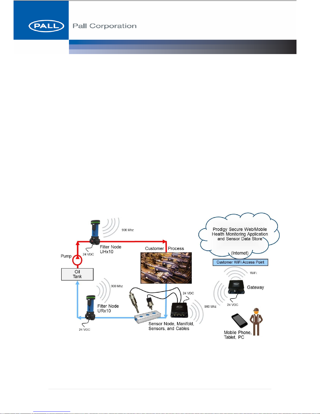
The Athalon®CM Platform Modular Filter Network is comprised of five main
components (SKU’s) and a portfolio of process sensors. The modular design allows the
end user maximum flexibility to efficiently integrate Athalon®CM into their equipment
arrangement without the expense of redundant components.
Minimum Athalon®CM System includes
• WiFi Gateway (SKU #1)
• Fluid Interface (SKU #2) with optional Sensor Manifold
• Filter Node – High pressure Filter Node (SKU #3&4) or Return Line Filter Node
(SKU#5)
Page 4

4
Athalon®CM & Crixus™ User Manual
1.1. Safety Information
Connecting Utilities
CAUTION: To ensure the safe and efficient operation of the
equipment and adherence to existing laws and
regulations, only qualified personnel should make
utility connections. Pall Corporation requires that
certified electricians complete all wiring connections
and that qualified personnel, working with Pall
Technology Services representatives if possible,
complete all plumbing work. Pall Corporation is not
responsible for and equipment warranties may be
voided from any damage or personal injury caused by
unqualified personnel performing utility connections
and/or installations!
1.2. Pall System Components
Pall Corporation is supplying a system comprised of WiFi Gateways, Filter Nodes, and
Fluid Interfaces to monitor the health of the hydraulic fluid within the system. Filter Nodes
and Fluid Interfaces monitor the state of the fluid directly through attached sensors, and
report wirelessly to the Wi-Fi Gateway. The Gateway then relays the system state through
the cloud to the backend application which monitors and controls the Filter Node and Fluid
Interface operation.
All external sensors along with associated cables for connecting the sensors to Filter Nodes
and Fluid Interfaces are supplied as part of the system. Power supplies and associated
cables are not supplied as part of the system and are the responsibility of the customer.
Page 5

5
Athalon®CM & Crixus™ User Manual
1.2.1. WiFi Gateway
1.2.1.1. Description
The Wifi Gateway provides the connection from the Athalon®CM Network to an
internet connection provided by the end user. The Athalon®CM Network connects
wirelessly to the WiFi Gateway via 915 Mhz LoRa radio. The WiFi Gateway can
connect to the end users WiFi access point wirelessly via 802.11 a/b/g/n protocol.
1.2.1.2. FCC Statement
This device complies with Part 15 of the FCC Rules and with Industry Canada’s
license-exempt RSSs. Operation is subject to the following two conditions: (1) this
device may not cause harmful interference, and (2) his device must accept any
interference received, including interference that may cause undesired operation.
The Wi-Fi Gateway does not contain any user-serviceable parts. Changes or
modifications not expressly approved by Pall Corporation could void the user's
authority to operate the equipment.
Note: This equipment has been tested and found to comply with the limits for a
Class A digital device, pursuant to part 15 of the FCC Rules. These limits are
designed to provide reasonable protection against harmful interference when the
equipment is operated in a commercial environment. This equipment generates,
uses, and can radiate radio frequency energy and, if not installed and used in
accordance with the instruction manual, may cause harmful interference to radio
communications. Operation of this equipment in a residential area is likely to cause
Page 6

6
Athalon®CM & Crixus™ User Manual
harmful interference in which case the user will be required to correct the
interference at his own expense.
This device uses RF energy to communicate. To reduce RF Exposure, this device
must be installed in a manner to ensure at least 20cm separation is maintained
between the device antenna and the body of the user or nearby people.
1.2.1.3. ISED (Canada) Notice
The device complies with Industry Canada’s license-exempt RSSs. Operation is
subject to the following two conditions: (1) this device may not cause harmful
interference, and (2) this device must accept any interference received, including
interference that may cause undesired operation.
Cet appareil est conforme aux normes d’exemption de licence RSS d’Industry
Canada. Son fonctionnement est soumis aux deux conditions suivantes: (1) cet
appareil ne doit pas causer d’interférence, et (2) cet appareil doit accepter toute
interférence, notamment les interférences qui peuvent affecter son fonctionnement.
1.2.1.4. Power Connection
CAUTION: To ensure the safe operation of the equipment the WiFi
Gateway must be powered from an NEC Class 2 power supply that is
certified as a Limited Power Source (LPS). Pall Corporation requires
that certified electricians complete all wiring connections from the WiFi Gateway to the external power supply, and from the external power
supply to the AC power mains.
The WiFi Gateway provides a barrel jack that is identified by the port label on the
Gateway for connection to an external DC power supply. The barrel jack has in
inside diameter of 2.5mm for the positive DC connection and a 5.5mm outside
diameter for the negative DC connection.
The DC supply must meet the following requirements for proper operation of the
Wi-Fi Gateway:
1. DC Output Voltage Range: 4.5 – 6.5 VDC
2. DC Output Current: 1.25 A Minimum
3. Supply must be an NEC Class II power supply that is certified as a
Limited Power Source (LPS)
Page 7

7
Athalon®CM & Crixus™ User Manual
The cabling used to connect the external DC supply to the Wi-Fi Gateway DC
power connector must comply with Article 725 of the NEC for Class 2 circuits.
1.2.1.5. Power Supply Installation
(TBD)
1.2.1.6. Technical Specifications
1.2.2. Fluid Interface
1.2.2.1. Description
The Athalon®CM Fluid Interface is a wall mounted electrical enclosure equipped
with circular M8 connectors for the flexible cords connecting the process sensors.
The Fluid Interface allows the end user to mount process sensors in a section of the
system operating below 20 bar. The process sensors are equipped with SAE 19261 compliant diagnostic tee fittings allowing the sensors to be easily installed in end
user piping systems.
1.2.2.2. FCC Statement
This device complies with Part 15 of the FCC Rules. Operation is subject to the
following two conditions: (1) this device may not cause harmful interference, and
(2) his device must accept any interference received, including interference that
may cause undesired operation.
The Fluid Interface does not contain any user-serviceable parts. Changes or
modifications not expressly approved by Pall Corporation could void the user's
authority to operate the equipment.
Functional Description
Specification/Range
Node communication
915 MHz LoRa Radio
WiFi network adapter
WiFi access point, 100m theoretical distance
Ambient Temperature
-25 – 60°C (-13 – 140°F)
Power requirement.
24VDC, 200mA
Ingress Rating Electronics
IP65 Minimum
802.11 Supported Protocols
2.4 GHz Wi-Fi 802.11 a/b/g/n
WiFi Authentication types
Open (no security), WEP-40, WEP-104, WPA (AES & TKIP), WPA2
(AES, TKIP & Mixed mode)
Page 8

8
Athalon®CM & Crixus™ User Manual
Note: This equipment has been tested and found to comply with the limits for a
Class A digital device, pursuant to part 15 of the FCC Rules. These limits are
designed to provide reasonable protection against harmful interference when the
equipment is operated in a commercial environment. This equipment generates,
uses, and can radiate radio frequency energy and, if not installed and used in
accordance with the instruction manual, may cause harmful interference to radio
communications. Operation of this equipment in a residential area is likely to cause
harmful interference in which case the user will be required to correct the
interference at his own expense.
This device uses RF energy to communicate. To reduce RF Exposure, this device
must be installed in a manner to ensure at least 20cm separation is maintained
between the device antenna and the body of the user or nearby people.
1.2.2.3. ISED (Canada) Notice
The device complies with Industry Canada’s license-exempt RSSs. Operation is
subject to the following two conditions: (1) this device may not cause harmful
interference, and (2) this device must accept any interference received, including
interference that may cause undesired operation.
Cet appareil est conforme aux normes d’exemption de licence RSS d’Industry
Canada. Son fonctionnement est soumis aux deux conditions suivantes: (1) cet
appareil ne doit pas causer d’interférence, et (2) cet appareil doit accepter toute
interférence, notamment les interférences qui peuvent affecter son fonctionnement.
1.2.2.4. Power Connection
CAUTION: To ensure the safe operation of the equipment, Fluid Interfaces must be
powered from an NEC Class 2 power supply that is certified as a
Limited Power Source (LPS). Pall Corporation requires that certified
electricians complete all wiring connections from Fluid Interfaces to the
external power supply, and from the external power supply to the AC
power mains.
The Fluid Interface provides a 4-pin M8 style connector plug that is identified by
the port label on the Fluid Interface for connection to an external DC power supply.
Page 9

9
Athalon®CM & Crixus™ User Manual
The DC supply must meet the following requirements for proper operation of the
Sensor Node:
1. DC Output Voltage Range: 24 VDC +/-10%
2. DC Output Current: 1.0 A Minimum
3. Supply must be an NEC Class II power supply that is certified as a
Limited Power Source (LPS)
The cabling used to connect the external DC supply to the Sensor Node DC power
connector must comply with the following requirements:
1. Connector on Sensor Node end of power cable must be a 4-socket
M8 style connector that will mate with: Phoenix Contact - 1453481
2. Cabling must comply with Article 725 of the NEC for Class 2
circuits
1.2.2.5. Power Supply Installation
(TBD)
1.2.2.6. Sensor Connections
The Fluid Interface provides two ports for connection to external sensors that
monitor the properties of the hydraulic fluid in the system. Cables for connecting
the external sensors are included with the system.
Page 10

10
Athalon®CM & Crixus™ User Manual
1.2.2.7. Fluid Properties Sensor
The Fluid Property Sensor (FPS) is used to measure the viscosity, density, dielectric
constant and temperature of the hydraulic fluid. This sensor connects to the ‘Fluid
Sensor’ port where indicated on the port label using the M8 to automotive style
connector cable.
Technical specifications for the FPS refer to the manufacturer’s data sheet (Measurement
Specialties Part No. FPS2800B12C4).
1.2.2.8. Water Sensor
FPS Sensor (Fluid Viscosity, Density, Temperature, TAN)
Seal Material
Viton Fluorocarbon
Housing Material
Stainless Steel
Port Option
M14 x 1.5 mm (male) To fit Port 2 Manifold
Maximum Working Pressure
20 bar (290 psi)
Rated Fatigue Pressure
20 bar (290 psi)
Measurement Viscosity
0.5 to 50.0 cp
Measurement Density
0.65 to 1.50 gm/cc
Measurement Dielectric
Constant
Qualitative Output
Flow Rate
>0.2m/s
Process Fluid Temperature
-40 – 90°C (-40 – 194°F)
Ambient Temperature
-40 – 60°C (-40 – 140°F)
Ingress Rating Electronics
IP 68 to IEC 60529 when assembled
Physical Dimensions
30 Hex x 73(H)mm. Installed on Sensor Manifold.
Page 11

11
Athalon®CM & Crixus™ User Manual
The Water Sensor is used to measure the dissolved water content in the hydraulic
fluid. This sensor connects to the ‘Water Sensor’ port where indicated on the port
label and using the M8 to 8-pin, M12 connector cable.
Technical Specifications refer to data sheet for Pall Water Sensor (WS12/WS13 Series).
1.2.3. Sensor Manifold
1.2.3.1. Description
The sensor manifold is an optional fitting that can be plumbed into a hydraulic
system and is used to install the Fluid Properties Sensor and the Water Sensor.
WS12 Water in oil sensor (Water content in oil %RH or PPM and Temperature °C or °F)
Seal Material
Viton Fluorocarbon
Housing Material
Stainless Steel
Port Options
½” NPT Internal Pipe Thread to ANSI B2.1
½” BSP (G) to ISO228 To Fit Port 3 Manifold
Maximum Working Pressure
20 bar (290 psi)
Rated Fatigue Pressure
20 bar (290 psi)
Process Fluid Temperature
-40 – 90°C (-40 – 194°F)
Ambient Temperature
-40 – 60°C (-40 – 140°F)
Electrical Connector
8 pin M12 Plug To IEC 61076-2-101
Measurement %RH
0 - 100% RH
Temp. Measurement Range
-25 – 125°C (-13 – 257°F)
Compatibility
The water sensor is not to be used in water based fluids
Ingress Rating Electronics
IP 68 to IEC 60529 when assembled
Physical Dimensions
30 Hex x 73(H)mm
Power Requirement
24V DC
Page 12

12
Athalon®CM & Crixus™ User Manual
1.2.3.2. Specifications
1.2.4. Filter Node
1.2.4.1. Description
Functional Description
Specification/Range
Manifold (9004D497)
Port Options
2” O-Ring Boss Per SAE J1926.
2” BSP (G) to ISO228
Maximum Working Pressure
20 bar (290 psi)
Rated Fatigue Pressure
20 bar (290 psi)
Seal Material
Fluorocarbon
Manifold Material
SG Iron (Chemical Black)
Sensor Port 1 Options
¼” Internal O RING Boss Per SAE J514
¼” BSP (G) to ISO228
Sensor Port 2
M14 x 1.5mm Internal O RING Boss Per ISO 6149-1
Sensor Port 3 Options
½” NPT Internal Pipe Thread to ANSI B2.1
½” BSP (G) to ISO228
Physical Dimensions
Diameter 120mm x 225(L)mm.
Page 13

13
Athalon®CM & Crixus™ User Manual
The Athalon®CM Filter Node is a Athalon housing mounted, electrical enclosure
equipped with a circular M8 connector for the flexible cord connecting the dP
Sensor. The Filter Node also connects to the lid mounted RFID antennae via
inductive coupling.
1.2.4.2. FCC Statement
This device complies with Part 15 of the FCC Rules. Operation is subject to the
following two conditions: (1) this device may not cause harmful interference, and
(2) his device must accept any interference received, including interference that
may cause undesired operation.
The Filter Node does not contain any user-serviceable parts. Changes or
modifications not expressly approved by Pall Corporation could void the user's
authority to operate the equipment.
Note: This equipment has been tested and found to comply with the limits for a
Class A digital device, pursuant to part 15 of the FCC Rules. These limits are
designed to provide reasonable protection against harmful interference when the
equipment is operated in a commercial environment. This equipment generates,
uses, and can radiate radio frequency energy and, if not installed and used in
accordance with the instruction manual, may cause harmful interference to radio
communications. Operation of this equipment in a residential area is likely to cause
harmful interference in which case the user will be required to correct the
interference at his own expense.
This device uses RF energy to communicate. To reduce RF Exposure, this device
must be installed in a manner to ensure at least 20cm separation is maintained
between the device antenna and the body of the user or nearby people.
1.2.4.3. ISED (Canada) Notice
The device complies with Industry Canada’s license-exempt RSSs. Operation is
subject to the following two conditions: (1) this device may not cause harmful
interference, and (2) this device must accept any interference received, including
interference that may cause undesired operation.
Cet appareil est conforme aux normes d’exemption de licence RSS d’Industry
Canada. Son fonctionnement est soumis aux deux conditions suivantes: (1) cet
appareil ne doit pas causer d’interférence, et (2) cet appareil doit accepter toute
interférence, notamment les interférences qui peuvent affecter son fonctionnement.
Page 14

14
Athalon®CM & Crixus™ User Manual
1.2.4.4. Power Connection
CAUTION: To ensure the safe operation of the equipment, Filter Nodes must be
powered from an NEC Class 2 power supply that is certified as a Limited
Power Source (LPS). Pall Corporation requires that certified electricians
complete all wiring connections from Filter Nodes to the external power
supply, and from the external power supply to the AC power mains.
The Filter Node provides a 4-pin M8 style connector plug for connection to an
external DC power supply. The DC supply must meet the following requirements
for proper operation of the Filter Node:
1. DC Output Voltage Range: 24 VDC +/-10%
2. DC Output Current: 1.0 A Minimum
3. Supply must be an NEC Class II power supply that is certified as a
Limited Power Source (LPS)
The cabling used to connect the external DC supply to the Filter Node DC power
connector must comply with the following requirements:
1. Connector on Filter Node end of power cable must be a 4-socket
M8 style connector that will mate with: Phoenix Contact - 1453481
2. Cabling must comply with Article 725 of the NEC for Class 2
circuits
1.2.4.5. Power Supply Installation
(TBD)
1.2.4.6. DPS Connection
The Filter Node provides a single port for connection of the Differential Pressure
Sensor (DPS) mounted at the base of the filter tube. This sensor connects to the M8
style socket connector on the electronics housing using the M8 to 5-pin, M12
connector cable.
Page 15

15
Athalon®CM & Crixus™ User Manual
Technical Specifications refer to data sheet for Pall Part No. RCA222.
1.2.4.7. Athalon Housing Specifications
1.2.4.7.1. Athalon H210 or H310 Filter Housings
Functional Description
Specification/Range
H310 / H210 Housing
Port Options H210
O-Ring Boss Per SAE J1926. 1” or 1 ¼”
BSP Thread To ISO228. 1” or 1 ¼”
Split Flange To SAE J518. 1” or 1 ¼”
Split Flange To SAE J518 Code 62. 1” or 1 ¼”
Differential Pressure Transducer
Seal Material
Viton Fluorocarbon
Housing Material
Brass
Port Options
¾”-16 UNF Thread To BS1580
To Fit housing Pall DPI Port.
Maximum Working Pressure
450 bar (6500 psi)
Proof Pressure
675 bar (9800 psi)
Burst Pressure (Typical)
1100 bar (15900 psi)
Rated Fatigue Pressure
0-400-0 bar (5800 psi)
Process Fluid Temperature
-25 – 90°C (-13 – 194°F)
Ambient Temperature
-40 – 60°C (-40 – 140°F)
Measurement Differential
Pressure Option
0.25 – 1.0 bar (3.6 – 14.5 psi)
1.0 – 4.0 bar (14.5 - 58 psi)
2.0 – 8.0 bar ((29 - 116 psi)
Pressure Dead Band
25% Full Scale (As Shown Above)
Temp. Measurement Range
0 – 100°C (-32 – 212°F)
Compatibility
Petroleum oils and synthetic hydraulic and lubrication fluids.
Ingress Rating Electronics
IP 65 to IEC 60529 when assembled
Page 16

16
Athalon®CM & Crixus™ User Manual
Port Options H310
Split Flange To ISO6162 (Metric) 1” or 1 ¼”
Side Manifold Mount. 1 ¼” Only
Top Manifold Mount. 1 ¼” Only
O-Ring Boss Per SAE J1926. 1 ¼”, 1 ½” or 2”
BSP Thread To ISO228. 1 ¼”, 1 ½” or 2”
Split Flange To SAE J518 Code 61. 1 ¼”, 1 ½” or 2”
Split Flange To SAE J518 Code 62. 1 ¼”, 1 ½” or 2”
Split Flange To ISO6162 (Metric). 1 ¼”, 1 ½” or 2”
Side Manifold Mount. 1 ¼”, 1 ½” or 2”
Top Manifold Mount. 1 ½” Only
Differential Pressure
1, 2 or 4 bard, 25% Dead band
Seal Material
Fluorocarbon
Filtration Rating
ß>2000 (In to out flow path)
Element Media Option
AZ (3 µm(c)), AP (5 µm(c)), AN (7 µm(c)), AS (12 µm(c))
and AT (25 µm(c)). (µm(c) where Beta =2000)
Flow
UH210 to 230 l/min (60 US gpm)
UH310 to 600 l/min (160 US gpm)
Process Fluid Temperature
-25 – 90°C (-13 – 194°F)
Ambient Temperature
-25 – 60°C (-13 – 140°F)
Maximum Working Pressure
400 bar (6000 psi)
Rated Fatigue Pressure
240 bar (3500 psi)
Filter Element P/N and Grade
Read from RFID tag on Filter Element
Filter Element Runtime
Data Stored on RFID Tag
Filter Element Lot Number
Data Stored on RFID Tag
Filter Element Activation Date
Data Stored on RFID Tag
Filter Element Hours in Service
Data Stored on RFID Tag
Filter Element Machine ID
Data Stored on RFID Tag
Filter Element dP Max
Data Stored on RFID Tag
Filter Element Temperature Max
Data Stored on RFID Tag
Ingress Rating Electronics
IP65 Minimum
Compatibility
Compatible with all petroleum oils and synthetic hydraulic
and lubrication fluids.
1.2.4.7.2. Athalon R310 Filter Housings
Functional Description
Specification/Range
R310 Housing
Port Options R310
O-Ring Boss Per SAE J1926. 1 ½” or 2”
BSP Thread To ISO228. 1 ½” or 2”
Split Flange To SAE J518 Code 61. 2” or 2½”
Split Flange To ISO6162 (Metric) 2” or 2½”
Differential Pressure
1, 2 or 4 bard, 25% Dead band
Page 17

17
Athalon®CM & Crixus™ User Manual
Seal Material
Fluorocarbon
Filtration Rating
ß>2000 (In to out flow path)
Element Media Option
AZ (3 µm(c)), AP (5 µm(c)), AN (7 µm(c)), AS (12 µm(c))
and AT (25 µm(c)). (µm(c) where Beta =2000)
Flow
R310 to 760 l/min (200 US gpm)
Process Fluid Temperature
-25 – 90°C (-13 – 194°F)
Ambient Temperature
-25 – 60°C (-13 – 140°F)
Maximum Working Pressure
41 bar (600 psi
Rated Fatigue Pressure
41 bar (600 psi)
Filter Element Presence
Detect that the Filter Element is Installed (via RFID)
Filter Element P/N and Grade
Read from RFID tag on Filter Element
Filter Element Runtime
Data Stored on RFID Tag
Filter Element Lot Number
Data Stored on RFID Tag
Filter Element Activation Date
Data Stored on RFID Tag
Filter Element Hours in Service
Data Stored on RFID Tag
Filter Element Machine ID
Data Stored on RFID Tag
Filter Element dP Max
Data Stored on RFID Tag
Filter Element Temperature
Max
Data Stored on RFID Tag
Power requirement.
24VDC, 100mA
Ingress Rating Electronics
IP65 Minimum
Compatibility
Compatible with all petroleum oils and synthetic hydraulic
and lubrication fluids.
2. Installation & Setup
2.1. Filter Node Installation
2.2. Providing a WiFi Access Point
The customer site must provide a WiFi access point (2.4 GHz Wi-Fi 802.11 a/b/g/n) that is
in range of the gateway.
If a WiFi access point is not available, but a wired/Ethernet connection is available at the
customer’s site, Pall recommends one of Cisco’s Meraki wireless LANs, such as the MR18
(https://meraki.cisco.com/products/wireless/mr18) indoor access point.
Page 18

18
Athalon®CM & Crixus™ User Manual
If a WiFi access point is not available and a
wired/ethernet internet connection is not
available, Pall recommends one of
CradlePoint’s wireless routers, such as the
MBR1200B wireless router with 3G/4G
wireless WAN connectivity
(https://cradlepoint.com/products/mbr1200b).
Wireless routers connect with the internet via
mobile broadband service available from
carriers in the customer’s region. A wireless
router provides a WiFi access point for the
Prodigy Gateway.
2.3. Configuring the Athalon®CM Gateway
The customer must configure the WiFi Gateway to communicate with an on-site WiFi
access point. The gateway associates to a WiFi access point using a service set identifier
(SSID) broadcast by the WiFi access point. The gateway securely communicates with the
following common WiFi security types:
Open (no security code), WEP-40, WEP-104, WPA (AES & TKIP), WPA2 (AES, TKIP
& Mixed mode). Each gateway comes with a unique MAC address assigned by the factory,
which may also be used for authentication.
Upon initial power-up, the WiFi Gateway will function as a WiFi Access Point. Using a
laptop or similar device, connect to the gateway’s network SSID, which is set to its MAC
address. Once connected, browse to the Configuration page at 192.168.10.1:7000/Config.
On the Configuration page, fill in the SSID, Password, and Security Mode of the WiFi
Access Point the gateway should communicate with, and press the “Submit” button (See
Figure below). The settings will be saved in the gateway. Once configuration is complete,
press the button on the gateway enclosure to switch the gateway from Access Point mode
to Client mode. The Prodigy gateway will now communicate with the cloud based server
through the WiFi access point. If the WiFi Access Point needs to be changed in the future,
the Prodigy gateway can be placed back into its WiFi Access Point mode by pressing the
button on the gateway enclosure.
7. Operation
8. Crixus Web Page
Page 19

19
Athalon®CM & Crixus™ User Manual
9. Mobile App
10. Troubleshooting
 Loading...