

Page 1
Multi-Well Plate Vacuum Manifold
Description
The Multi-well Plate vacuum manifold is an anodized aluminum manifold that has
been designed and optimized for the vacuum filtration of the AcroPrep
™
AcroWell
with the necessary O-ring and gasket. The control block includes the vacuum
pressure gauge, vacuum metering valve, vacuum release valve and the 1/4 inch
hose barb for vacuum line attachment. Included with the vacuum manifold unit is a
Delrin spacer block designed to accommodate standard 350 µL receiver plates.
The spacer block has been optimized to reduce the space between the receiver
plate and the filter plate during vacuum filtration. A spacer block that has been
optimized to work with our 1 mL plate is available separately. An accessory kit that
contains an additional O-ring, gasket and allen wrench is also included with the
vacuum manifold unit.
lines of multi-well filter plates. The vacuum manifold comes complete
Ordering Information
Prod. No. Description Packaging
5017 Multi-well Plate Vacuum Manifold 1/pkg
5014 1 mL Receiver Plate Spacer Block 1/pkg
5015 350 µL Receiver Plate Spacer Block 1/pkg
5016 Replacement Accessory Kit (Includes O-Ring, 1/pkg
Note: the 350 µL Receiver Plate Spacer Block can be used to accomodate 384
well receiver plates as well.
gasket and allen wrench)
Specifications
Materials of Construction
Vacuum Manifold: Anodized aluminum
Gasket: EDPM (Ethylene propylene)
O-ring: Silicone
Spacer blocks: Delrin
Dimensions
Length: 17.48 cm (6.88 in)
Width: 12.37 cm (4.87 in)
Height: 8.05 cm (3.17 in)
Weight: 6.27 lbs
Maximum Operating Vacuum
71.12 cm Hg (28 in Hg).
Note: The multi-well plate vacuum manifold can be used with multi-well filter plates
that meet the specifications set forth by the Society for Biomolecular Screening
(SBS).
Instructions for Use
To set the vacuum manifold to a desired negative pressure setting prior to filtration,
follow the steps listed below.
11. Switch the on/off valve to the off position (See Figure 3).
12. Attach the vacuum line to the 1/4 inch hose barb.
13. Place a receiver plate on top of the vacuum manifold.
14. Turn on the vacuum pressure. You may need to press lightly on the receiver
plate to engage the vacuum seal.
15. Adjust the negative pressure to the desired setting by adjusting the metering
valve.
16. Turn off the vacuum pressure and remove the receiver plate. The vacuum
manifold is now set at the desired setting.
To filter the AcroPrep or AcroWell filter plates follow the steps listed below.
11. If collecting the filtrate, remove the top chamber of the vacuum manifold. The
indentations on the sides of the manifold allow for the top portion of the
manifold to be easily removed. If collecting the retentate, skip to step 3.
12. Place the appropriate spacer block into the lower chamber of the vacuum
manifold. The vacuum manifold can be used with any size receiver plate.
350 µL receiver plates: To use a 350 µL 96 well or 384 well receiver plate,
place the large spacer block (PN 5015) into the lower chamber of the vacuum
manifold. Place the 350 µL 96 well or 384 well receiver plate on top of the
spacer block.
1 mL receiver plates: To use 1 mL receiver plates, place the small spacer block
(PN 5014) into the lower chamber of the vacuum manifold. Place the 1 mL
receiver plate on top of the spacer block. (You can also use a standard 350 µL
receiver plate in place of the 1 mL spacer block.)
2 mL receiver plates: To use 2 mL receiver plates, place the 2 mL receiver plate
directly into the lower chamber of the vacuum manifold.
™
and
Instructions for Use (cont.)
13. Before replacing the top chamber of the vacuum manifold, ensure that all
surfaces are free from dirt, debris and any particulate matter that may have
accumulated on the vacuum manifold, O-ring and gasket.
Note: If the O-ring and gasket are not clean, you will not obtain a proper seal.
14. Replace the top chamber of the vacuum manifold.
15. Place the filter plate on the gasket located on the top chamber of the vacuum
manifold. Ensure that the gasket is clean.
16. Ensure that the on/off switch is in the position (See Figure 3).
17. Connect the vacuum line to the 1/4 inch hose barb.
18. When ready to evacuate the filter plate, turn the on/off switch on the vacuum
manifold to the on position. You may need to press lightly on the filter plate to
engage the vacuum seal.
19. The wells will begin to evacuate/empty once the vacuum has been applied to
the chamber.
10. If you need to adjust the vacuum pressure up or down, adjust by moving the
metering valve located to the right of the vacuum pressure gauge.
11. When all of the wells have completely evacuated, turn the on/off valve to the off
position. To release the residual vacuum pressure that remains in the chamber,
push the release valve located to the left of the vacuum gauge. The release
valve will allow the pressure within the manifold chamber to return to
atmospheric pressure and reduce the potential for cross contamination and
spraying of the filtrate. Do not release the vacuum by pulling the corner of
the plate as it will degrade the manifold gasket. You can also tap the top of
the filter plate prior to removing it to release any hanging drops that may be
attached to the outlet tips.
12. Remove the filter plate and place it aside for further processing or dispose of
properly.
13. If collecting the filtrate, remove the top chamber of the vacuum manifold from
the lower portion of the vacuum manifold.
14. Remove the receiver plate from the lower chamber of the vacuum manifold and
utilize the filtrate for further processing.
To r eplace the O-ring follow the steps below.
11. Remove existing O-ring from the bottom of the upper chamber.
12. Ensure that the new O-ring and O-ring groove are free from dirt, debris and
particulate matter.
13. Place new O-ring into place.
To r eplace the gasket follow the steps below.
11. With the allen wrench provided, remove the 12 screws located on the bottom
portion of the upper chamber.
12. Separate the top ring from the bottom section of the upper chamber.
13. Remove the old gasket and clean the gasket pocket area of any dirt and
debris.
14. Place the new gasket into the gasket pocket. Place the top ring back onto the
bottom section of the upper chamber. Ensure that the alignment posts on the
bottom section fit into the alignment holes in the top ring.
15. Invert the upper chamber and replace the 12 screws.
16. Lightly tighten the four corner screws with the allen wrench, then tighten all 12
screws. Once this is completed recheck the screws with the allen wrench to
ensure all screws are tightly secured.
17. The manifold is now ready for use.
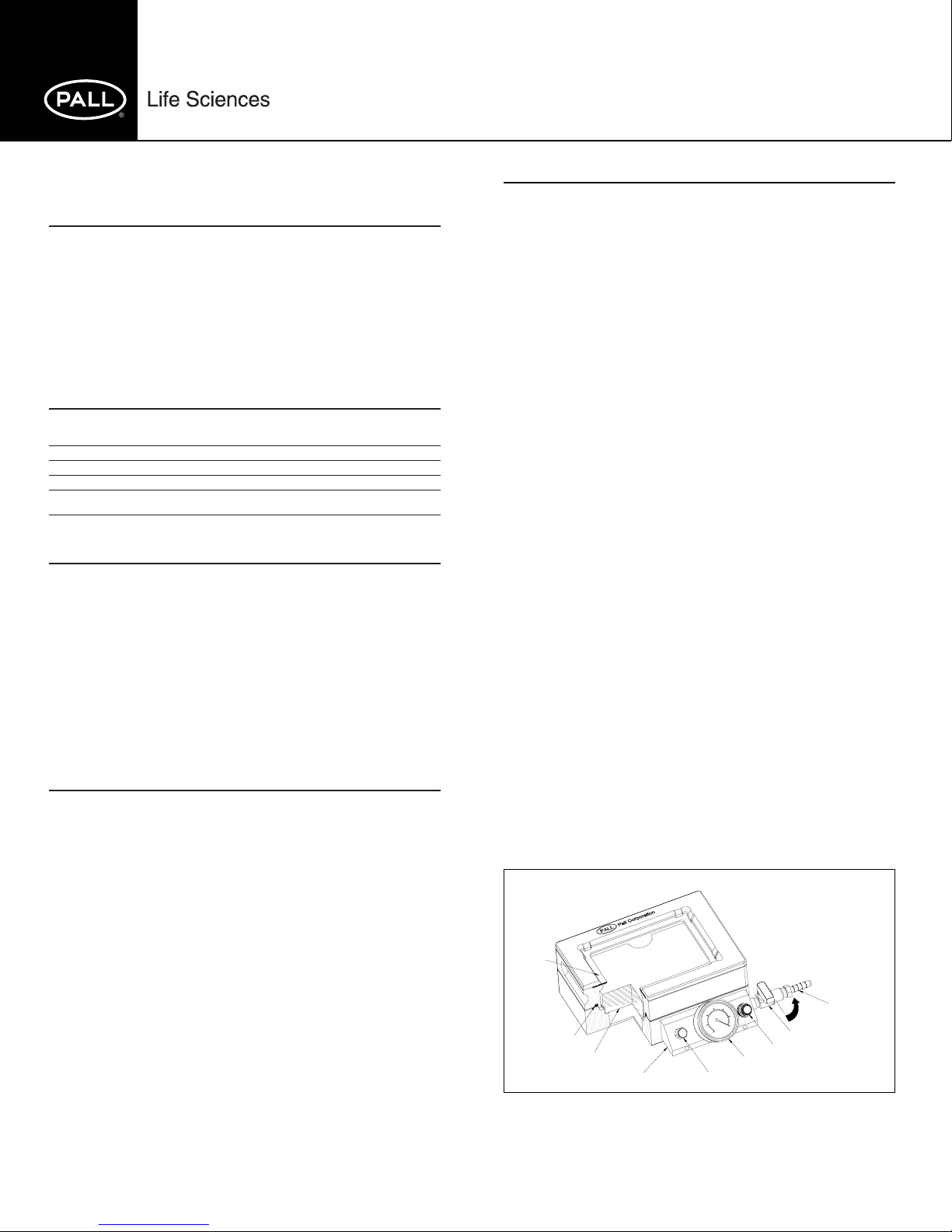
Figure 1
Gasket
1/4 inch hose barb
On/Off switch
Vacuum metering valve
Vacuum pressure gauge
Figure 1
O-ring
350 µL spacer block
Control block
Vacuum release valve
Page 2

Instructions for Use (cont.)
Figure 2Figure 2
gasket
1 mL receiver
plate
1 mL receiver plate
spacer block (PN 5014)
2 mL receiver
plate
350 µL receiver
plate
350 µL receiver plate
spacer block (PN 5015)
Lower chamber
Upper chamber
Figure 2
Note: A 384 well receiver plate can be interchanged with the 350 µL receiver plate
if using a 384 well filter plate.
On/Off valve
On position
Complementary Products
™
AcroWell
Membranes exhibit high binding capacities for proteins and nucleic acids.
AcroPrep
variety of molecular biology, analytical and high throughput sample preparation and
detection applications.
96-well Filter Plates with BioTrace™NT and BioTrace PVDF
™
96 and 384-well Filter Plates are an excellent platform for a wide
WARNING
Employment of the products in applications not specified, or failure to follow
all instructions contained in this product information insert, may result in
improper functioning of the product, personal injury, or damage to property
or the product. See Statement of Warranty in our most recent catalog.
Figure 3
Vacuum relief valve,
push down on button
to activate.
Off position
Metering valve fully open when
knob is turned completely down.
Turn counter clockwise to lower
vacuum (minimum vacuum
setting is 3" Hg).
Pall Life Sciences
600 South Wagner Road
Ann Arbor, MI 48103-9019 USA
For ordering or technical information:
Tel: 734-665-0651
800-521-1520 (in USA)
Fax: 734-913-6114
Visit Pall Life Sciences on the
Internet: www.pall.com/Lab or
e-mail us at: Lab@pall.com
Offices:
Australia, Lane Cove, NSW, 02-9428 2333
Austria, Wien, 043-1-49 192 0
Canada, Ontario, 905-542-0330
Canada, Québec, 514-332-7255
China, P.R., Beijing, 86-10-8458 4010
France, St. Germain-en-Laye, 01 30 61 39 92
Germany, Dreieich, 06103-307 333
India, Mumbai, 91-22-5956050
Italy, Milano, 02-47-79-61
Japan, Tokyo, 3-3495-8319
Korea, Seoul, 2-569-9161
Poland, Warszawa, 22-811 12 83
Russia, Moscow, 095 787-76-14
Singapore, 65-389-6500
Spain, Madrid, 91-657-9876
Sweden, Lund, 46-0-46 15 84 00
Switzerland, Basel, 061-638 39 00
Tai w an, Taipei, 2-2545-5991
United Kingdom, Portsmouth, 023 92 302600
Pall, , AcroPrep, AcroWell, and BioTrace are trademarks of Pall Corporation.
® indicates a registered trademark in the USA.
©2003, Pall Corporation, 09/03 PN 88293A
 Loading...