


Palintest
®
Potalab
®
+
(C)
Advanced Portable Water Quality
Laboratory (Physico-Chemical)
Wagtech
®
ZI PTW 10010C

Palintest
®
2
Who We Are
Over the last 20 years the Wagtech®name has become synonymous with water testing
in the most extreme circumstances and remote locations.
Developed for a range of applications, from long term surveillance to rapid response testing
in an emergency, the Wagtech
®
kits provide a robust solution to testing key water quality
parameters in the field.
Acquired by Palintest
®
in 2011, the manufacture and support of the Wagtech®portable
water quality laboratory range has now been integrated into the Palintest®product family.
Further information regarding the Wagtech®product range can be found at: www.palintest.com

Contents
Chapter Page
1
2
3
4
5
6
7
8
Kit Layout
Introduction
Photometer 7500
Compact Turbimeter
Digital pH Meter
Digital Conductivity Meter
Digital Arsenator
Appendix 1 - Reagents and Consumables
4
8
9
31
38
42
51
53
3

4
Potalab®+ (C) Water Test Kit - Layout
Fig 1. Potalab®+ (C) Physico-Chemical test kit layout.
Coloured circles indicate the chapter colour in which their use is explained.
1
Kit Layout

Function Equipment
Kit Layout
1
Parameter Testing Using
Photometer 7500
Turbidity Measurement Compact Turbimeter
pH Measurement Digital pH Meter (+ electrode)
Conductivity Measurement Digital Conductivity Meter (+ electrode)
Arsenic Testing Digital Arsenator
1
Photometer 7500 BT
2
Cuvettes (+ under Photometer)
3
Reagent Tablets (Chlorine DPD) ‘DPD1 & 3’
4
Reagent Tablets (Fluoride)
5
Reagent Tablets (Ammonia)
6
Reagent Tablets (Nitrate) ‘Nitratest’ and Tube (6a)
7
Reagent Tablets (Nitrite) ‘Nitricol’
9
10
Turbidity Standard & Cuvettes
11
Silicon Oil
12
13
14
15
Reagent Tablets (Sodium Borohydride A2)
16
Reagent Powder (Sulphamic Acid)
17
Filter Paper Holders (Black & Red)
18
Arsenator Filter Papers
Other Items Dilution Tube
22
23
Tube Brush & Lint Free Cloth
24
Dilution Tube - Sample Bottle Inside
25
Instruction Manual
5

6
Potalab®+ (C) Water Test Kit - Layout
Fig 2. Potalab®+ (C) Physico-Chemical test kit with instruments removed to show equipment beneath.
Coloured circles indicate the chapter colour in which their use is explained.
1
Kit Layout

Function Equipment
Kit Layout
1
Parameter Testing Using
Photometer 7500
Turbidity Measurement Compact Turbimeter
pH Measurement Digital pH Meter (+ electrode)
Conductivity Measurement Digital Conductivity Meter (+ electrode)
Arsenic Testing Digital Arsenator
Other Items
1
Photometer 7500 BT
2
Cuvettes (+ under Photometer)
8
Photometer Cap (under Photometer)
9
10
Turbidity Standard & Cuvettes
12
13
14
19
Conical Flask (under Arsenator)
20
In-Filter Arsenic Trap (under Arsenator)
21
pH Buffer and Conductivity Solutions
(under Arsenator)
7

2
Introduction
8
2.0 Introduction
Ideally suited to longer term surveillance and professional monitoring, the Potalab®+ (C) Advanced
Portable Water Quality Laboratory provides portable analysis of a wide and comprehensive range of key
drinking water quality parameters where the most important factor is to obtain laboratory levels of accuracy.
Built for physico-chemical water testing, the Potalab
®
+ (C) is the most advanced portable water
quality laboratory available today.

3.0 Introduction
Photometer 7500 BT
3
The Palintest Photometer 7500 Bluetooth
is a direct-reading, waterproof photometer for
determining key water quality parameters for
drinking water, wastewater and process water
samples. Designed for both portable and
laboratory use, the Photometer 7500 Bluetooth
should always be used with genuine Palintest
reagents for optimal performance.
The fundamental operating technique applied to
the Photometer 7500 Bluetooth is based on the
principles of optical absorbance and scattering
of visible light.
Optical absorbance techniques are based on the use
of Palintest (spectro)photometric reagents, creating
visible colours with specific analytes upon reaction.
The intensity of colour produced is measured with
the Photometer 7500 and the data compared to
the stored calibration data to deliver the final result.
Optical scattering techniques produce small
particles to scatter the source beam, the amount
of scatter providing a result for the concentration
of parameter under test.
For more information regarding the science behind
both photometric and turbidimetric analysis
technology please visit www.palintest.com/know.
The Photometer 7500 is provided with
programmed methods for a comprehensive range
of water quality parameters. Upon choosing a test
the instrument automatically selects the required
parameters for accurate analysis including
wavelength and reaction time. Upon completion
of the test optional follow-on tests are available
and results can be converted to alternative units
of expression e.g. mg/l to ppm, N or NH
.
3
The Photometer 7500 Bluetooth offers a choice of
connectivity to download all or selected results and/or
upload up to 30 User Defined Tests. Choose from
Bluetooth 4.0 wireless connectivity or USB connection.
Bluetooth 4.0 (also known as Bluetooth SMART or Low
Energy) connection allows seamless data exchange
using the Palintest Aqua Pal app, available for iOS
and Android devices. See Section 3.11 for more details.
USB connection via the port located at the rear
of the instrument provides a choice of either
‘Hard Disk’ mode or serial communication mode.
See Section 3.4 for more details.
The Photometer 7500 Bluetooth offers a choice
of either mains power via the USB port or using
three 1.5V ‘AA’ batteries (supplied).
The Photometer 7500 Bluetooth is supported
with a two year warranty and a full range of
service, calibration and technical support. Support
resources are available at www.palintest.com
relating to both products and applications.
3.1 Quick Start
Photometer 7500 Layout
Adaptive Cuvette Holder
(do not insert finger!)
LCD screen
with backlight
Numerical keys
for Hotkey
operation and
text entry
USB
Port
Light
Cap
Navigation
Keys
On/
Off
Photometer 7500 Interface
The LCD screen features a selectable backlight
with the screen separated into four clear, easy
to read zones:
1
2
3
4
9

3
Photometer 7500 BT
10
1 Mode or Test Identification.
2 Dialogue screen - prompts and choices will be
displayed as a list. Select using up/down arrows.
3 Info Panel - displays status icons, date/time
and Sample/Operator ID
4 Action select - choices are displayed as a row.
Use left/right arrows to select.
Info Panel Icons
3.2 Taking a Sample
The first critical step in any analysis is taking a
representative sample. When selecting a sample point
a number of care points are recommended as follows:
• Ensure the sample point is safe to access and
follow all relevant/required precautions
• When sampling from a tap or outlet, remove
any attachment and clean the tap/outlet with
a dry cloth before allowing the tap/outlet to
run for 1 minute prior to sample collection
• When sampling from a river or stream take the
sample as near as possible to the main flow and
not too close to the edge where the water may be
still and unrepresentative of the sample as a whole
• Rinse any sample container repeatedly with
the sample to prevent any cross contamination
from previous samples
• Once collected the sample must be processed
immediately or as quickly as possible, especially
for highly reactive species such as chlorine for
example. The use of a portable field test kit
makes this possible. However if the delay
between sample collection and analysis is likely
to be several hours chill the sample to preserve
and prevent potential microbiological growth
• Samples containing solid particles can interfere
with photometric analysis. Either allow solids
to settle and decant the clear liquid or filter
the sample prior to analysis
3.3 Starting up the Instrument
Power Supply
The Photometer 7500 Bluetooth is designed to
be powered either from alkaline batteries or via
the USB port.
When operating on battery power, the battery
level is indicated on the Info Panel. A minimum
voltage of 3.0V is needed to operate the
photometer and a flashing battery symbol
indicates a critically low battery. Change batteries
immediately or switch to alternative USB power.
The Photometer 7500 Bluetooth will automatically
power down when power is no longer capable
of providing acceptable performance.
To power via the USB port, use the supplied
cable connected either to the mains adaptor
or a PC. The USB icon will appear when the USB
connection is made and battery power will no
longer be consumed.
The Photometer 7500 Bluetooth has a back-up
battery mounted internally to save instrument
settings and data during power loss and
instrument idle periods.
Replacing Batteries
The battery compartment is located on the base
of the instrument and secured by four screws.
Remove the cover and install a complete set of
new batteries, observing the correct polarity as
indicated. Use 3 x 1.5V ‘AA’ alkaline batteries
or equivalent. See Section 3.9 for more details.
To avoid corrosion damage through leakage,
remove batteries from the instrument if it is
to be stored or left unused for a long period.
Start-up Screen
Description
Battery status
Bluetooth connected
Bluetooth on, not connected
Upper/lower case text/number entry
Hotkey Entry Mode Enabled
USB connected
Hard Drive/COM port mode
Icons

Photometer 7500 BT
3
The default start-up screen on power up is the
‘Choose a Test’ screen.
To access the Mode menu press the left arrow
key to highlight ‘Menu’ and OK.
To choose a test use the up/down arrows to scroll
through the list and press OK on the desired parameter.
Mode Screen
The Photometer 7500 has four operating modes
as follows:
Choose a Test
The Choose a Test mode is the standard operating
mode for taking photometer readings and is the
default start-up screen on power up. See Section
3.5 for more information.
Hotkey Test List
Assign up to 10 of the most frequently used tests
for single button access when in Hotkey mode,
indicated by the icon in the Info Panel. More
information on how to set up and use Hotkey
mode can be found in Section 3.4.
System Mode
Personalise your Photometer 7500 Bluetooth and
manage stored data within the System mode.
Options include setting Operator/Sample IDs,
interrogating the result log and defining the
instrument operating conditions. See Section
3.4 for further information.
Check Standard Mode
Validate performance of your Photometer 7500
Bluetooth using Palintest Check Standards.
See Section 3.7 for more information.
3.4 System Mode
Personalise your Photometer 7500 Bluetooth
and access the data log via the System Mode.
Scroll up or down using the appropriate keys to
see all available options. The options and available
settings are as follows:
Log
The Photometer 7500 Bluetooth has an internal
data log for up to 500 data points. The data is
stored automatically upon completion of the test
and automatically overwrites the oldest result when
the memory is full. The data log is unaffected by
power on/off.
Each data point is stored in a comma-separated
values (CSV) format and consists of date,
time etc.
Selecting Log offers two choices:
View - to view individual data points use the
up/down keys. Data is stored in chronological order
with the most recent result shown by default.
Scroll through results using the up/down arrows.
Select Back to return to the previous menu.
11

3
Photometer 7500 BT
12
Clear - the entire log can be deleted from the
Photometer 7500 Bluetooth if the instrument is
not locked (see System Lock). Selecting Clear
produces the following screen:
Data can be downloaded via either Bluetooth
(see Bluetooth Log Transfer) or USB connection
(see USB Interface).
Operator ID
The Photometer 7500 Bluetooth offers the option
to create up to 12 unique alphanumeric Operator
IDs. Operator IDs are added to the result data
automatically but deleting IDs does not affect the
result log.
To create a new Operator ID, select Operator ID
and use the up/down keys to select a blank field.
Select New and press OK.
Alphanumeric characters are entered/edited using
the 0-9 keys or the up/down keys. Press and hold
the 1 key to toggle between upper case, lower
case and numeric characters.
After entering a character, the cursor automatically
moves to the next position if no key is pressed.
Alternatively press the right key.
Up to 10 characters can be added for Operator IDs,
including spaces.
To edit characters use the left/right keys to select
the desired character. Press and hold the left key
to delete the character or change the character
using the entry mode.
When the Operator ID is correct press the OK key
to create the ID and return to the Operator ID
list. The new Operator ID will be displayed in the
Operator list.
Choose the Operator ID to be used by scrolling
through the list and pressing the OK key on the
desired choice. The instrument will return to the
System menu.
To modify or delete an existing Operator ID,
highlight the ID and select Edit. Choose either
Edit to modify the existing entry or Delete to
remove it from the list.

Photometer 7500 BT
3
Sample ID
The Photometer 7500 Bluetooth offers the option
to create up to 24 unique alphanumeric Sample IDs.
Sample IDs are added to the result data automatically
but deleting IDs does not affect the result log.
To create a new Sample ID, select Sample ID
and use the up/down keys to select a blank field.
Select New and press OK.
Alphanumeric characters are entered/edited using
the 0-9 keys or the up/down keys. Press and hold
the 1 key to toggle between upper and lower
case characters.
After entering a character, the cursor automatically
moves to the next position if no key is pressed.
Alternatively press the right key.
Up to 10 characters can be added for Sample IDs,
including spaces.
To edit characters use the left/right keys to select
the desired character. Press and hold the left key
to delete the character or change the character
using the entry mode.
new Sample ID will be displayed in the Sample list.
Choose the Sample ID to be used by scrolling through
the list and pressing the OK key on the desired choice.
The instrument will return to the System menu.
To modify or delete an existing Sample ID, highlight
the ID and select Edit. Choose either Edit to modify
the existing entry or Delete to remove it from the list.
Bluetooth
The Photometer 7500 Bluetooth features the
latest Bluetooth 4.0 (also known as Bluetooth
Low Energy or Bluetooth SMART) for wireless
communication with external devices.
The Palintest Aqua Pal app provides seamless data
exchange with the Photometer 7500 Bluetooth,
provides data trend analysis and user-defined
action limits for key parameters.
Additional data management functionality is provided
by the Palintest Portal (www.palintestportal.com).
Uploaded data can be shared with colleagues
and customers within your User Group(s) and
integrated into customised reports. See Section
3.11 for more information on the Aqua Pal app
and the Palintest Portal.
When the Sample ID is correct press the OK key to
create the ID and return to the Sample ID list. The
There are four options available in the Bluetooth menu:
• Bluetooth Communications ON - activate the
Bluetooth and make the Photometer 7500
Bluetooth visible for connection/pairing
• Bluetooth Communications OFF
• Bluetooth Log Transfer - transfer historical log
data to the Aqua Pal app when connected
to a remote device
• Bluetooth Device ID - create a unique device
name for the Photometer 7500 Bluetooth to
discriminate between multiple connections
13
3
Photometer 7500 BT
14
Bluetooth Communication On
Select this option to enable Bluetooth
communications allowing the instrument to be
paired with a suitable Bluetooth SMART enabled
device. Visit www.palintest.com\know for more
information regarding available/suitable Bluetooth
SMART devices.
The Bluetooth icon is shown in the Info Panel
when Bluetooth is enabled. Connection status
is shown as follows:
indicates the Bluetooth is activated
and connected to an external device
indicates the Bluetooth is activated
but the Photometer 7500 Bluetooth
is not connected to an external device
Bluetooth Communication Off
Selecting this option disables the Bluetooth
communications module. The Bluetooth icon
is not visible on the Info panel.
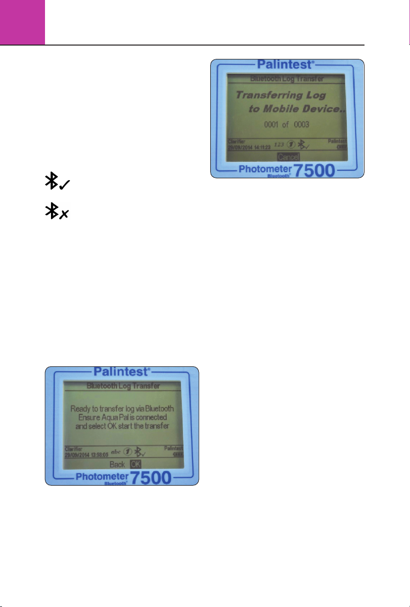
Bluetooth Log Transfer
Selecting this option transfers all or a selected
group of results stored in the log to the paired
mobile device.
The Photometer 7500 Bluetooth will validate the
paired connection and confirm readiness to transfer.
Transferring selected data will require specification
of the result log window e.g. from result 40
to result 100 to be transferred selectively.
Press OK to transfer the data log. The data will
transfer in series. Each data point is validated by
the Aqua Pal app prior to upload of the next.
If the connection is lost the Photometer 7500
Bluetooth will prompt for re-connection. If
connection is not required or possible press Exit
to disable Bluetooth and cancel the log transfer.
The message ‘Log transfer is complete’ will be
shown when all data points have been uploaded
successfully. Press OK to return to the previous menu.
Bluetooth Device ID
A number of Photometer 7500 Bluetooth instruments
may be available to connect to a remote device,
although only one active connection is possible at
any time. A user-defined Bluetooth Device ID ensures
simple pairing between the desired Photometer
7500 Bluetooth and the Palintest Aqua Pal app.
Creating and/or editing Bluetooth Device ID is
identical to Operator and Sample ID creation.
USB Interface
The waterproof USB interface provides both
communication between the Photometer 7500
Bluetooth and a PC and an alternative mains
power source via the adaptor.
When connected the USB icon will appear, replacing
the battery icon in the Info Panel, as power will
be preferentially drawn from the external source.
The USB data interface has a choice of two
operating modes - Hard Drive and COM Port. The
current status of the USB connection is shown on
the Info panel when the USB lead is connected.
Toggle between COM Port and Hard Disk mode in the
System -> USB menu by selecting the desired option.
The USB connection supports software update and
data download through a simple ‘drag and drop’
approach when operated in Hard Disk mode.

Photometer 7500 BT
3
Hard Drive
The instrument appears as a removable hard drive
when connected to a PC in Hard Disk mode. Upon
connection the remote drive will have the
following files included:
• 7500_***.afx.*** where * represent
version numbers of software - this is
the operating software for the Photometer
7500 Bluetooth
• Log.txt - the data log file stored in a
comma separated value (csv) format
Operating software or calibration library can
be updated by dragging a new version to the
instrument - contact support@palintest.com
for new software if this option is required. Any
updates to operating software will be notified
via the www.palintest.com\know portal.
Downloading the result log is carried out by dragging
the LOG.txt to the local desktop and opening the file
with any program that can open CSV format files.
earlier models of Palintest instruments. In this mode,
the PC requires installation of a USB virtual COM
Port driver, available from www.palintest.com/know,
and the availability of software operating as a
virtual com port.
A large number of third-party software systems
are available to provide data upload and remote
control of testing using the COM port mode.
Please contact your local Palintest representative
for more details.
Test Selection Method
The Photometer 7500 Bluetooth offers two
distinct methods of selecting test parameters Phot Number Entry Mode or Hotkey Entry Mode.
Phot Number Entry Mode is active by default.
Switching to Hotkey mode is carried out by
enabling Hotkey Entry Mode in the Test Selection
Method menu.
Select Hotkey Entry Mode and press OK. If ‘Hotkey
Entry Mode’ is enabled, the icon is displayed
on the Info panel.
Only one Test Selection Method is permitted at
any time.
For more information regarding extracting and
opening result logs using the Hard Disk mode
visit www.palintest.com/know.
COM Port
The instrument behaves as if connected to the PC
serial port via RS232 when connected in COM Port
mode, allowing remote control from an external
software system and data upload. This allows
backwards compatibility with software written for
Phot Number Entry Mode
All methods/calibrations (including User Defined
Tests) are identified by a unique three-digit ID
Phot Number. When operating in Phot Number
Entry Mode, access the test of choice quickly by
typing the three-digit number when in either the
Choose a Test screen or any result screen.
For example, to access the Phot 002 Total
Alkalinity test press ‘002’, ‘02’ or just ‘2’ to
load the method instantly.
15

3
Photometer 7500 BT
16
Hotkey Entry Mode
This option provides single button access to the
ten most frequently used tests by assigning each
to a unique position on the numerical keypad.
To assign a test to a specific Hotkey (0-9), firstly
ensure that ‘Hotkey Mode’ is enabled. This is
shown by the indicator on the Info Panel.
Select the Hotkey Test List from the Mode menu.
The ten available positions are listed along with
assigned or empty slots.
Select the Hotkey to assign (0-9) and use the
up/down arrows to highlight the required
parameter/method from the Choose a Test list.
Press OK and the test will be assigned to the
defined number.
Units
The Photometer 7500 Bluetooth offers the choice
of result expressed in mg/l, ppm, mmol/l, µmol,
g/l and µg/l.
Changing the result units will not affect the result log.
Dilution Factor
When samples are above the test range, indicated
by >> on the result screen, a dilution procedure can
be used. Setting Dilution Factor to On will prompt
the Photometer 7500 Bluetooth to automatically
request the dilution factor when carrying out a test.
Change the dilution factor by using the up/down
arrows or manually type the dilution factor. The
instrument will automatically correct the result
for the dilution and display the corrected result
(which will also be stored in the result log).
The maximum dilution factor permitted is 99.
If the calculated result exceeds the available number
of permitted characters >> will be displayed
NOTE: do not use sample dilution when
measuring pH or alkalinity.
Photometer 7500 BT
3
System Lock
To prevent unauthorised or inadvertent changes
to the System settings or log deletion a four digit
code can be used to lock several options.
The default code is set to 6812. To change the
System Lock code follow the on-screen prompts
to choose a memorable four digit number.
When the System Lock is applied, the items accessible
within the System Mode are limited until the unlock code
is entered. Access is limited to viewing the result log,
adjusting the backlight, contrast and Bluetooth settings.
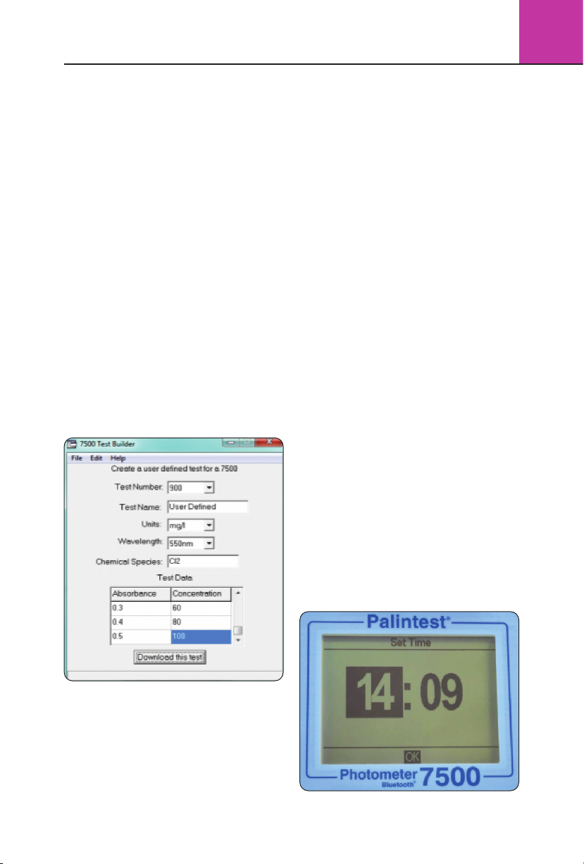
User Defined Tests
In addition to the many available calibrations/
methods, the Photometer 7500 Bluetooth provides
additional capability for up to 30 User Defined
Tests. A User Defined Test is built using a table of
calibration data consisting of up to 10 data pairs
of absorbance and concentration.
Download or request a copy of Usertestbuilder.exe
(suitable for Windows operating systems) from
our websites to define the details and calibration
data as shown below:
Alternatively save the test data as a *.txt file and
drag and drop onto the Photometer 7500 Bluetooth.
User Defined Tests are stored in Phot Numbers 900 - 929
to avoid confusion with standard Palintest calibrations.
Press OK once the test has been uploaded
to view the test in the User Defined Test list.
A number of options are available within
the Edit User Defined Test menu:
BACK return to the previous menu
ADD add additional User Defined Tests
EDIT upload new data for the selected test
DELETE remove the test from the instrument
For more information regarding creation and
upload of User Defined Tests please visit
palintest.comknow
Accessing User Defined Tests can be carried out by
assigning to Hotkeys (if enabled), scrolling through
the list of tests or entering the required Phot Number.
Language
Select the desired local language for operation,
choosing from English, French, Spanish, German,
Italian and Chinese (Mandarin). The selection of
language will also adjust appropriate tests and
units to local convention as required.
Set Time/Set Date/Date Format
All test results are recorded automatically in the
Data Log and appended with date and time (plus
additional information). Date and time are stored on
an internal clock, supported by a coin cell battery.
To correct the time select Set Time from the
System menu.
Use the up/down keys to adjust the hour; press
the right key to select and adjust the minutes.
Connect the Photometer 7500 Bluetooth to the
PC using the USB cable provided, ensuring the
instrument is set to Hard Drive mode.
Once data is complete press “Download this test”
to transfer the method details and calibration.
The Photometer 7500 Bluetooth will respond
with Test Data Accepted.
17

3
Photometer 7500 BT
18
Press OK when the correct time is set.
To correct the date select Set Date from the
System menu.
Use the up/down keys to adjust the day/month/year,
using the left/right keys to select the field.
Press OK when the correct date is set.
The Date Format can be set to DD/MM/YYYY or
MM/DD/YYYY as required. To select the required
format highlight the desired choice and press OK.
Time Out
When operating using battery power the
Photometer 7500 Bluetooth provides automatic
power-off as a power-saving measure. Three
settings are provided:
Normal 5 minutes
Long 15 minutes
Off (disables Time Out)
The time intervals begin after the last key is pressed
or activity takes place.
Time Out is automatically disabled when the
instrument is powered by USB supply and during
a Bluetooth data log transfer.
Back Light
The instrument display features a high intensity
backlight to support use in low light conditions.
The backlight is designed to use minimal energy
but activating the Backlight will naturally consume
battery power more rapidly. The settings available
for Backlight are:
Backlight Auto-Dim Backlight activates on any
key press and dims after
15 seconds automatically.
Backlight On Backlight is on permanently
Backlight Off Backlight is off permanently
LCD Contrast
In addition to the Backlight, the default contrast
setting for the display can be adjusted using the
up/down keys when light conditions are difficult.
The display provides a sequence of alternating
squares to give visual indication of the correct
settings to apply.
When complete/acceptable press the OK key.
Version
The serial number of the instrument and the
software version are displayed. The instrument
serial number will be required for technical
support and servicing/warranty and can also
be found on the base of the instrument.
3.5 Analysing Samples
The Photometer 7500 Bluetooth provides simple,
accurate and reliable analysis of key drinking
water, wastewater and process water parameters.
Selecting the required parameter and performing
the test are supported through on-screen prompts
and comprehensive test instructions.
The principle of photometric testing is based on the
absorption or scattering of a measured intensity

Photometer 7500 BT
3
of incident light compared to the light intensity
reaching the detector array. The light intensity is
determined as Transmittance (%T) or Absorbance (A)
and compared to calibration tables stored within the
Photometer 7500 Bluetooth. The stored calibration
tables convert %T or A to results in a variety of
units (mg/l, ppm etc.) as defined in Section 3.4.
Calibration tables are defined by Palintest based
on the measurement of reference standards using
Palintest reagents. To achieve the best quality
results there are a small number of care points:
1 Always use the provided light cap to prevent
ambient light affecting the results.
2 Ensure Sample and Blank cuvettes are clean, dry
and inserted correctly into the sample chamber,
using the allocated orientation mark to align.
3 Always blank the instrument with untreated
sample prior to analysis.
Additional guidance is provided in Section 3.8
Photometric Testing Hints and Tips
Selecting Test Parameters
The Photometer 7500 Bluetooth offers a number
of choices to select the parameter to test:
Phot Number Entry - use the numeric keypad
to enter the unique Phot Number to directly
access any programmed calibration (including
User Defined Tests). This method will not be
available if the Photometer 7500 Bluetooth is
operating in Hotkey Entry Mode.
Hotkey Entry - use the numeric keypad to
directly access up to 10 of the most commonly
used tests. When operating in this mode the Info
panel will display the icon and Phot Number
Entry mode will be disabled.
Choose a Test - available in either Phot Number
Entry or Hotkey Entry modes, the full list of test
parameters is available by selecting Choose a Test
and scrolling using the up/down keys. When the
desired parameter is highlighted, press the OK
key to access the method. Tests are presented in
Phot Number order.
When the required test is selected the Photometer
7500 Bluetooth automatically selects the correct
wavelength and sets additional method parameters
as required.
Test method protocols are defined in detail in the
Palintest Phot Book, supplied with the Photometer
7500 Bluetooth, including the reagents and
accessories that may be required.
When a test is selected, the Photometer 7500
Bluetooth screen will display a number of screens
and options to guide the user through the testing
process, as described in the following pages.
Dilution Factor
If selected in the System menu, the initial screen will
request the defined Dilution Factor to apply to results.
If Dilution Factor is not active this screen will not
be shown.
Results shown on the final screen have automatically
been corrected for dilution prior to display. Corrected
results will also be stored in the log.
Blanking the Photometer 7500 Bluetooth
Blanking the photometer is a key first step in
photometric analysis, effectively removing the
potential entrained sample colour and minor amounts
of turbidity from calculation of analytical results.
To blank the photometer, prepare a Blank cuvette
using untreated sample i.e. sample that has not
been reacted with any reagents. If the sample is to
be diluted or physically treated (filtered for example)
before analysis, use the same dilution/treatment
for the Blank cuvette.
When accessing the test method the Photometer
7500 Bluetooth will request the user to
Insert Blank.
19

3
Photometer 7500 BT
20
Insert the Blank cuvette and press OK.
The Photometer 7500 Bluetooth will determine
the absorbance due to the sample colour at
all wavelengths simultaneously and store in
temporary memory for use in analysis.
Upon successful blanking the Photometer 7500
Bluetooth will automatically move to the Insert
sample stage of the analytical method.
If the sample is too highly coloured to support
effective blanking and subsequent analysis the
error message “Error 9 is caused by the blank
cuvette being too dark. Check the correct cuvette
is being used”.
Ensure the blank cuvette is being used, not the
sample plus reagent cuvette. Sample colour can
be reduced by dilution with clean water; the
dilution selected should take account of the
expected concentration of parameter under test.
Blank results are stored in the temporary memory
of the Photometer 7500 Bluetooth and will be
used for all subsequent tests until:
• The instrument is powered down (temporary
memory is lost/deleted)
• A new Blank reading is taken - this option is
available on accessing any subsequent test at
the base of the screen. Repeat the blanking
process if the sample changes significantly
or a new sample is under test
• Some tests use a reversed blanking process
where a coloured blank cuvette may be required.
When changing between standard tests and
‘reverse blank’ test, a new blank sample will be
requested by the Photometer 7500 Bluetooth
If the blank value generated in this step is not
detectable an error message will be displayed
“Error 7 is caused by too much ambient light. Try
using the light cover provided with the instrument”.
See Section 3.8 Photometric Testing Hints and
Tips for more advice regarding effective blanking.
Reading Results with the
Photometer 7500 Bluetooth
Assuming a suitable blank has been recorded,
the next step of the photometric analysis process
is to carry out the reading step.

Photometer 7500 BT
3
Prepare a Sample cuvette following the method
instructions provided in the Palintest Phot Book.
Select Read at the base of the screen and press OK.
At the Insert sample prompt, insert the sample
cuvette ensuring it is clean and dry and oriented
correctly using the location mark.
Press OK to begin the measurement process.
The screen will display Reading...
At the completion of the measurement process
the result is displayed on screen.
Timer
Many photometric methods require a reaction time
to develop optimise sensitivity, the recommended
time period being documented in the Palintest Phot
Book and included as part of the method parameters
programmed into the Photometer 7500 Bluetooth.
Tests requiring a reaction time will have the option to
select an automatic timer to count down the reaction
time required. While in the Insert sample screen use
the right key to move the cursor to highlight Timer.
The programmed reaction time will be displayed.
Press OK to Start the countdown.
Three options will be displayed:
Stop cancel the countdown timer
Exit exits the countdown screen and
returns to the Insert sample
screen. The countdown will
continue and the current time can
be seen by selecting Timer. At the
end of the countdown an audible
alarm will sound to indicate the
sample is ready to read. Select
OK to read the sample manually.
Exit and Read exits the countdown screen and
automatically reads the sample
at the completion of the allocated
time period.
Changing Result Units of Expression
Many chemical species have a number of
alternative units that can be used for reporting
results e.g. Phosphate can be expressed as
PO
or P for example.
4
21

3
Photometer 7500 BT
22
Where alternative units of expression for results
are available the ▲▼ symbols will be displayed
next to the current result units. Use the up/down
arrows to change the units of expression as
required. Values are modified automatically.
Results stored in the log will be in the units
selected on screen, changing the chemical species
will add an entry to the log showing the updated
result and species parameter selected.
Follow-on Tests
A number of photometric methods have additional
optional methods that can be applied, known as
Follow-on Tests e.g. Phot 008 Total Chlorine follows
Phot 007 Free Chlorine. Follow-on methods are
usually either based on further reagent addition to
the sample just measured for sequential parameters
or used to correct for potential/known interferences.
Follow-on tests are clearly defined in the Palintest
Phot Book and, if available, are accessed via the
Follow-on option located at the right hand side
of the options.
To access the Follow-on test, highlight Follow-on
and press OK. The next method is automatically
loaded and operated in the usual manner.
NOTE: if no viable result is produced during the first
stage of a sequential test method, the Follow-on
option will be automatically removed.
For correction methods, the data log will store
the corrected result automatically along with all
other results in the sequence.
All Follow-on methods have unique allocated Phot
Numbers but not all can be directly accessed.
Follow-on methods that cannot be directly
accessed are not listed in the Choose a Test list
for Hotkey Entry but will be available following
a viable result in the initial test stage.
3.6 7500 Test Methods
Fluoride
Range: 0-1.5mg/l (ppm) F
Colour change: Colourless - Red/Yellow
1 Fill test cuvette with sample to the 10ml mark.
2 Add one Fluoride No 1 tablet,
crush and mix to dissolve.
3 Add one Fluoride No 2 tablet,
crush and mix to dissolve.
4 Stand for 5 minutes.
5 Take photometer reading.
Chlorine-Free
Range: 0-5.00mg/l (ppm) Cl
2
Colour change: Colourless - Purple/Red
1 Rinse test cuvette with sample leaving
two or three drops in the tube.
2 Add one DPD 1 tablet, crush tablet and then
fill the test tube with sample to the 10ml mark.
Mix to dissolve tablet fully and ensure no
particles remain.
3 Take photometer reading immediately.
The result may drift on standing.
4 Retain test solution if the Total Chlorine
Follow-On Test is required.

Photometer 7500 BT
3
Chlorine-Total
Range: 0-5.00mg/l (ppm) Cl
Colour change: Purple/Red from Free Chlorine
Test increases in intensity
Carry out this test on the solution
remaining from the Free Chlorine test.
1
Add one DPD 3 tablet, crush and mix to dissolve.
2 Stand for two minutes to
allow full colour development.
3 Take photometer reading after
two minutes have elapsed.
Note: To obtain Combined Chlorine residual
subtract Free Chlorine result from Total Chlorine result:
Combined Chlorine =
Total Chlorine - Free Chlorine
2
Nitrate
Range: 0-20mg/l (ppm) N
Colour change: Colourless - Red
1 Take a clean Nitratest Tube (PT 526). Using the
Measuring Syringe (PT 361) add 1ml of sample.
Fill the Nitratest Tube to the 20ml mark with
deionised water.
2 Add one level spoonful of Nitratest Powder and
one Nitratest tablet. Do not crush the tablet.
Replace screw cap and shake tube well for exactly
one minute then allow contents to settle.
3
Then, either: Invert tube gently 2 or 3 times and
then allow to stand for at least two minutes to
ensure complete settlement. Remove screw cap and
wipe around top with a clean tissue. Decant clear
solution into test cuvette, filling to the 10ml mark.
or: Using the Palintest Filtration Set (PT 600) filter
a portion of the solution through a GF/B filter
paper into a test cuvette filling to the 10ml mark.
4
Add one Nitricol tablet, crush and mix to dissolve.
5 Stand for 10 minutes.
6 Take photometer reading.
Ammonia
Range: 0-1.00mg/l (ppm) N
Colour change: Yellow - Green
1 Fill test cuvette with sample to the 10ml mark.
2 Add one Ammonia No 1 tablet and one
Ammonia No 2 tablet, crush and mix to dissolve.
3 Stand for 10 minutes.
4 Take photometer reading.
3.7 Calibration/Validation
Your Photometer 7500 Bluetooth is delivered with
a calibration certificate validating the performance
of the instrument as it leaves Palintest.
We recommend annual service and calibration
of all photometric instruments in normal use.
The Photometer 7500 Bluetooth also includes an
automatic routine to validate analytical performance
using certified Palintest Check Standards. Accessed
via the Mode menu, the Check Standard Mode
provides a field method of ensuring your instrument
is operating within defined specifications and also
a troubleshooting method for unexpected results.
Every Palintest Check Standards set is supplied with
certified values expressed as %T (Transmission), derived
from traceable reference materials. Acceptable tolerances
are defined on the certificate and are automatically
specified within the Photometer 7500 Bluetooth.
Check Standard Mode
Access Check Standard Mode from the Mode screen.
Highlight Check Standard Mode and press OK.
Nitrite
Range: 0-0.5mg/l (ppm) N
Colour change: Colourless - Red
1 Fill test cuvette with sample to the 10ml mark.
2
Add one Nitricol tablet, crush and mix to dissolve.
3 Stand for 10 minutes.
4 Take photometer reading.
23

3
Photometer 7500 BT
24
Two choices are offered:
Enter Check use the up/down keys to
Standard Values adjust the displayed values
to match the certificate
Check Standard insert the Check Standards
Measurement in the defined order to
generate a validation report
Enter Check Standard Values
Each standard has two values assigned, for two
individual wavelengths.
Use the up/down keys to adjust the values to match
the certificates, following the order defined on the
display. Press OK when the correct value is shown
and the prompt will forward to the next value.
Upon completion the message Check Standard
Values assigned successfully will be displayed.
Press OK to return to the Check Standard Mode menu.
Check Standard Measurement
Follow the on-screen prompts to insert the Check
Standards in the defined order. The Photometer
7500 Bluetooth will automatically measure the
Transmittance at the required wavelength.
Upon completion of the sequence the results are
displayed on screen with pass or fail status.
If the Check Standard Mode reports a failure,
see Section 3.9 Troubleshooting for guidance or
contact your local Palintest supplier.
3.8 Photometric Testing Hints and Tips
Photometric analysis is a very powerful technique,
providing accurate analysis of a wide range
of critical drinking water, wastewater and
environmental parameters.
A complete guide to the science behind photometric
(also known as colorimetric) analysis can be found
in the Know portal at www.palintest.com/know/
Palintest has focused on simplifying the test
methods and equipment used for this technique
but there are still a number of ways to ensure the
results you generate are as accurate as possible:
1 Always use genuine Palintest reagents when
using the programmed test methods. Each
parameter has a unique calibration which
has been generated using Palintest reagents.
Alternative reagents may follow the same
general methodology but can differ
substantially in formulation and colour
generated thereby rendering the calibration
and hence results inaccurate.
2 Always correct for the blank value - any
inherent colour in the sample (which may not
be visible to the naked eye) will offset the
result if the blank step is omitted. If the sample
colour is too intense for the photometer to
blank use dilution with deionised water to
reduce the intensity. Remember to dilute the
sample to the same extent for analysis.
3 Always respect the reaction time specified
within the instructions. Some methods
produce instant colour whereas others require
a reaction time to reach full development.
Taking a reading before the reaction time
has elapsed may lead to low results.
4 The presence of solids, either large or in the
form of turbidity, can adversely affect the
quality of results by preventing incident light
from reaching the detector. The blanking step
can reduce the impact of turbidity interference
but large solid particles must be removed prior
to analysis. Solids can be removed by filtration
prior to analysis or, if the solids are settleable
and will not lie in the optical path, allowing
them to settle in the photometer cuvette can
be acceptable.

Photometer 7500 BT
3
5 Calibration curves relate transmission/
absorbance to concentration to provide result
data but not all calibration ranges are linear.
Frequently at higher concentrations the curve
‘flattens’ leading to higher potential variability
in results. If greater accuracy is required than
can be achieved on neat samples then dilution
can be used to improve performance.
6 Ensure the photometer cuvette is clean, has
no droplets on the outside and not excessively
scratched. Good technique is to wipe the outside
surface of the cuvette prior to inserting into
the optical chamber to prevent contamination
of the optical system.
7 Always use good quality, genuine Palintest
cuvettes. Use the orientation mark to ensure
repeatable positioning of the cuvette.
8 Maintain the cleanliness of the optical chamber
by only inserting clean cuvettes. If the chamber
becomes fouled or sample is spilled the base
can be removed for cleaning access. Clean the
optical chamber with a soft cloth. Do not use
abrasive chemicals or scouring agents.
9 Always use the light cap provided to prevent
ambient light affecting results. This is especially
relevant when operating in strong sunlight or
other light conditions.
10 Ensure your Photometer 7500 Bluetooth is
operating effectively by using Palintest Check
Standards and the Check Standard Mode (see
Section 3.7 Calibration/Validation) and having the
photometer serviced and calibrated at regular
intervals. Calibration is recommended at 12
month intervals for normal usage and can be
provided by your local Palintest distributor.
3.9 Troubleshooting
The Photometer 7500 Bluetooth features selfdiagnostic software and hardware to optimise
performance and battery life. The Info Panel
indicates the status of the Photometer 7500
Bluetooth and any specific fault conditions are
defined and displayed on screen.
Optical Errors
I have an Error 9 message
Error 9 is caused by the blank cuvette being too
dark to allow the blanking step to be carried out.
Check that the correct cuvette is being used i.e. ensure
the sample cuvette is not being used for blanking.
If the sample is too highly coloured or contains
significant solids, dilute and repeat the blanking step.
If the problem persists and the blank cuvette is not
the issue, clean the optical chamber by removing
the access cover and cleaning with a soft cloth.
Do not use corrosive or abrasive chemicals.
I have an Error 7 message
Error 7 is caused by too much ambient light
reaching the detector. Use the light cover
provided with the instrument.
Check Standard Issues
How do I maintain my Check Standards?
Check Standards are manufactured to precise
values/tolerances, certified against traceable
reference materials and provided in sealed
cuvettes. Do not decant or remove the sealed
cap from the Check Standard.
Ensure the Check Standard cuvettes are clean
and dry using lint-free cloths before inserting
into the optical chamber.
Insert the Check Standard aligning the orientation
arrow towards the front of the optical chamber.
Values assigned to calibration standards are
defined at 20-25°C. Extremely high or low
ambient temperatures can affect Check Standard
results so ensure standards are at the defined
temperature to effectively validate.
Check Standards have a two year shelf-life, after
which the colours will no longer be valid. Please
dispose of the expired standards after this period
according to the MSDS.
My Check Standard validation has failed
Photometers may fail the Check Standard validation
step due to the requirement for service/calibration.
Contact your local Palintest partner for service
and support.
Ensure the Check Standards are inserted correctly,
using the orientation mark to align and inserted
fully. Use the light cap to prevent any ambient
light interference.
Service/calibration is recommended at annual
intervals in normal operation.
25

3
Photometer 7500 BT
26
Bluetooth Issues
The Photometer 7500 Bluetooth features
the latest Bluetooth SMART connectivity.
I can’t connect the Photometer
7500 Bluetooth to my device
Ensure your device is Bluetooth SMART ready.
Previous versions of Bluetooth (also known
as Bluetooth Classic) will not connect to the
Photometer 7500 Bluetooth. Check your device
specification or visit www.bluetooth.com
to see the latest list of SMART ready devices.
I can’t download my results
to my connected device
The Info Panel will show the connected status
of the Photometer 7500 Bluetooth. Ensure the
connected icon is displayed.
If more than one remote device is running the
Aqua Pal app, check that the correct device is
connected to the Photometer.
The connected device is indicated at the base
of the Aqua Pal results screen.
I can’t upload my data
to the Palintest Portal
Ensure you have a reliable internet connection
to exchange data with the Palintest Portal. Once
uploaded data can be shared within your secure
user group and downloaded for report generation.
Bluetooth Error Messages
The Photometer 7500 Bluetooth communicates
seamlessly with the Palintest Aqua Pal app. In the
event of any errors the Photometer 7500 Bluetooth
will display either of the following messages:
The Photometer 7500 Bluetooth is not receiving a
response from the Palintest Aqua Pal app but the
remote device is connected. This will appear 10s
after a result transmission has started and no
valid response has been received.
Re-start the Aqua Pal app and select Retry.
When the Bluetooth connection to the remote
device the following message is shown:
Check the Bluetooth has not been inadvertently
deactivated in the mobile device settings.
NOTE: the Photometer 7500 will not appear as
a ‘paired device’ in the settings of a Bluetooth
SMART device.
Battery/Power Issues
My batteries are running out too quickly
Use good quality batteries and always replace
the batteries completely when indicated on the
Info Panel. The battery compartment is located
underneath the Photometer 7500 Bluetooth and
secured by four screws.
Remove the battery cover and replace batteries
as a set.
Refit the battery cover ensuring the cover is tight
enough to prevent water ingress. Do not overtighten
as this will damage the screw housings.
The Photometer 7500 Bluetooth has a number
of power-saving features such as auto-dim of
the backlight and automatic power down after
inactivity (See Section 3.4). Activating these features
will prevent power being used unnecessarily.
Bluetooth can also be de-activated if not required.
Using the USB port to provide power will
automatically prevent battery power being consumed
when mains or external power is available.

My photometer will not switch on
The Info Panel provides an ongoing indication of
power available from the battery supply. When the
voltage available falls below 3.0V the Photometer
7500 Bluetooth will not switch on as the available
power will not be sufficient to provide effective
photometric testing.
Use the USB cable to provide an alternative
power supply. If the photometer still fails to
switch on, contact your local Palintest partner
for service support.
My USB power supply is not working
Ensure your PC is not operating in power save
mode or the mains supply is not isolated.
Replace the cable with an alternative to ensure
the cable is not faulty.
USB Connection Issues
I cannot download my data
Check the USB mode is set to Hard Disk, not COM
port mode. In Hard Disk mode the data can be
‘dragged and dropped’ as with a conventional
memory stick and is available in CSV format.
Opening CSV data files can be accomplished by a
number of text editing or spreadsheet programs.
Where do I find the COM port drivers?
The latest drivers are available at
www.palintest.com
COM port drivers are provided for Windows
operating systems (Windows Vista, XP and 7).
Care and Maintenance
The Photometer 7500 Bluetooth contains no userserviceable parts internally. User maintenance is
only recommended for cleaning of the optical
chamber, changing batteries and validating
performance using the Check Standard Mode.
Cleaning the Optical Chamber
The optical chamber has been designed to
support removal and cleaning with a lint-free
cloth as required by removal of the access cover.
Photometer 7500 BT
Access
Cover
Screws
Do not use any of the following agents
when cleaning this optical chamber:
• Abrasive cloths
• Corrosive chemicals
• Any organic solvents
Do not overtighten the screws on re-assembly
to avoid damaging the access cover.
Replacing the Batteries
Remove the four retaining screws from the
battery cover and gently prise the cover free.
Battery
Cover
Access
Screws
Replace all batteries at the same time.
Ensure on replacing the battery cover that
the gasket is correctly located to prevent any
water ingress. Tighten the screws carefully
but do not overtighten.
3
27

3
Photometer 7500 BT
28
3.10 Technical Specifications
Instrument Type Dual light source photometer offering direct-reading of
pre-programmed test calibrations, Absorbance and Transmittance
Optical System
Optical Source Dual LED sources with optical filters
Optical Detectors Silicon photodiodes
Peak Wavelengths 450nm, 500nm, 550nm, 570nm, 600nm, 650nm
Wavelength Selection Automatic
Bandwidth ±5nm
Range 1 - 100%T (0-2.3 Abs)
Accuracy ± 1.0% T
User Interface
Display 320 x 240 pixel LCD with contrast adjustment
Backlight Timed, on key press with auto-dim and off
User Interface On-screen prompts available in English, French, Spanish,
German, Italian, Turkish and Mandarin (Chinese).
Keypad Numeric keypad with assignable Hotkeys. Four navigation keys and OK key
Physical
Size (W x L x H) 150 x 250 x 70mm
Weight 975g
IP Rating IP67
Power Supply
Batteries 3 x 1.5v ‘AA’ batteries
Lifetime 40 hours (typical use, backlight off, ‘AA’ alkaline cells)
Mains 5V DC, 900mA delivered via USB port
Power Management Auto-switch off (user selectable between 5-15 minutes on battery) or continuous operation
Power Saving User control for Backlight and Bluetooth to minimise battery consumption
Test Methods
Tests Available Pre-programmed for Palintest tablet reagent and Tubetests
®
format tests
Also operates in Absorbance and Transmittance modes
User Defined Tests Up to 30 user calibrations can be entered. Up to 10 points per calibration
Test Selection Phot number entry, Hotkey or selection from a list
Test Cuvettes 12-20mm OD with automatic cuvette centering
Result Units g/l, mg/l, ppm, mmol/l, µmol/l, µg/l, ppb
Blanking Automatic blanking at all wavelengths. Blank value
stored in memory until power off or new blank recorded
Connectivity
USB USB Type B Connector. Waterproof connector available
Wireless Palintest Bluetooth SMART profile
Data Management
Instrument Memory Non-volatile storage
Memory Capacity Up to 500 data sets. Each data set includes date, time, Sample ID,
Operator ID, method number, method name, result, units
Sample IDs Up to 24 at any time
Operator IDs Up to 12 at any time
Data Download To computer via USB using Hard Disk or COM port mode. Wireless Bluetooth SMART
download, either instantly or as a data batch, using a connected device running
the Palintest Aqua Pal app. Optional Palintest Portal data management available
Data Output Format Plain text
Software Upload Software update by ‘drag and drop’ in USB Hard Disk Mode
Photometer 7500 BT
3
3.11 Palintest Aqua Pal App
and the Palintest Portal
What is the Aqua Pal App?
Generating reliable and accurate water test
data is only part of the process of managing
drinking water, wastewater, process water and
environmental compliance.
Collating the data quickly and sharing with
other members of the team can be the difference
between effective control and failing to adhere
to local regulatory standards.
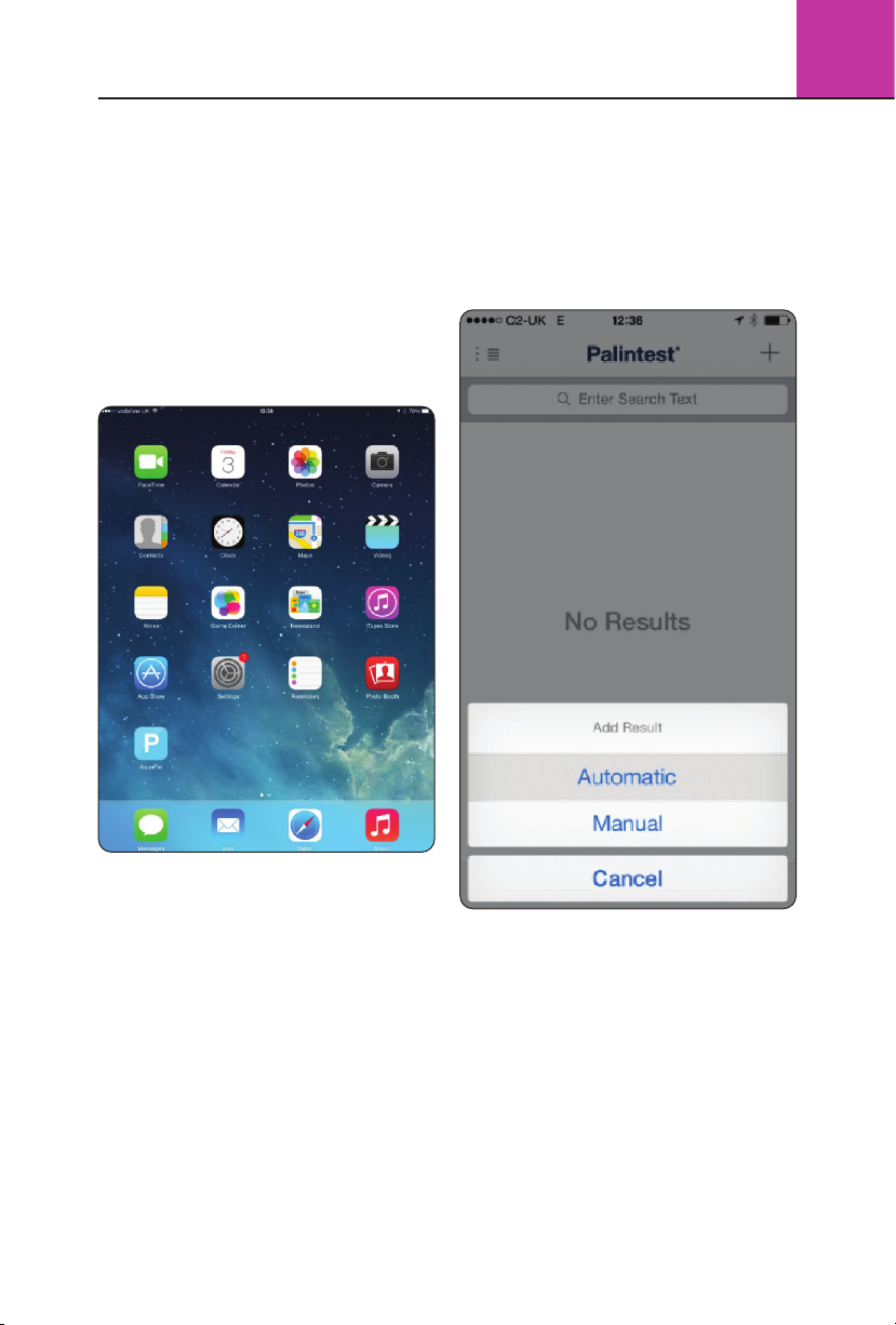
Connecting to the Aqua Pal App
Enable Bluetooth on the Photometer 7500
Bluetooth. The icon will appear on the Info Panel
showing Bluetooth is on but not connected.
Open the Aqua Pal app and log in using your
registration credentials. Choose whether to
use automatic or manual result addition.
The Palintest Aqua Pal app is intrinsic in the
process of storing, sharing and managing data
produced by the Photometer 7500 Bluetooth
and also allows for additional data to be added
manually for the Big Data experience.
The Aqua Pal app is available for both iOS and
Android (version 4.3 or later) devices that are
equipped with Bluetooth SMART connectivity.
On first use the Aqua Pal app will require a
registration step for both the app and the secure
Palintest Portal. An internet connection is required
to process the request as it will involve a second
stage authentication via the provided email address.
Once the sign up process is completed the Aqua
Pal app and Palintest Portal are ready to go.
To connect the Photometer 7500 Bluetooth press
the ‘+’ symbol in the top right hand corner of
the device screen. This will produce the list of all
locally advertising Bluetooth SMART devices.
29

3
Photometer 7500 BT
30
Select the Photometer 7500 Bluetooth you wish
to connect (see also Section 3.4 - Adding Device
Name) and Aqua Pal will link. The Info Panel
will display the connected Bluetooth icon.
Previously connected instruments are
stored in the app for future selection.
Once connected, data can either be uploaded
automatically (if selected) or direct from the
log (all or a selected group).
Manual data entry is also possible for results
generated with non-Bluetooth instruments or
external devices such as TDS meters, flow meters
or level sensors.
Connecting with the Palintest Portal
Also included with the Aqua Pal app is
the secure Palintest Portal found at
https://palintestportal.com
Data stored in the Aqua Pal app can be uploaded
to the Palintest Portal when an internet connection
is available.
Data stored within the portal can be shared with
team members using the User Group functionality.
Simply assign team members to the User Group
and they can view data generated by logging
in to the portal.
Results stored within the portal can be filtered
by date, sample ID, Operator ID and parameter.
Data can be viewed graphically over time with
the status (in spec, nearing limit, out of spec)
being indicated by a simple colour key.
Further Information
The full guide to the Aqua Pal app and the Palintest
Portal are available at www.palintest.com
and available for download from the Palintest
Know portal.

4.0 Introduction
The Compact Turbimeter is the latest addition to the Palintest
Compact Meter range which includes photometers for chlorine,
ozone, chlorine dioxide and ammonia.
The Turbimeter operates according to the ISO 7027 method
for measurement of turbidity, utilising two NIR light sources
at 860nm as part of the QuadoptiX™ optical system.
The Turbimeter is provided with accessories and
standards to support effective use of the instrument.
For technical support or to report issues with this
product please contact Palintest or your supplier.
Compact Turbimeter
4
4.1 QuadoptiX™ Technology
The Palintest Compact Turbimeter utilises
QuadoptiX™ technology for turbidity
measurement - a sophisticated optical approach
designed to ensure turbidity measurements
are as accurate and repeatable as possible in
even the most challenging circumstances.
Turbidity measurements are carried out by analysis
of light scattered at 90° to the incident light
(nephelometric measurement) at levels below 40NTU.
Above 40NTU the recommendation is to measure
also at 180° to ‘compensate’ the 90° readings.
QuadoptiX™ technology uses two independent
sources and two independent detectors to provide
effectively four entirely autonomous measurement
systems in the same instrument, allowing multiple
validation of all results for greater accuracy.
4.2 Start-up and Start Page
To switch the unit ‘on’, press the POWER button
and release. An audible beep will confirm the
instrument is on. Switch ‘off’ by holding the
POWER button for 1 second.
The LCD screen is provided with a backlight option
that can be set to on/off in the ‘System’ menu
(see Section 4.4). The initial default setting is ON.
After initialisation, the Start page will appear
and display, initially defaulted to Mode screen
and showing three options:
1 Reading - Select the mode to measure
turbidity or suspended solids (see Section 4.5).
2 Calibration - Choose either SDVB, Total
Suspended Solids or to Restore the factory
calibration values (see Section 4.7).
3 System - view or set Log (result and calibration),
Operator ID, Sample ID, Units, Language, Set Time,
Set Date, Date Format, Software Version and
switch the backlight on/off (see Section 4.4).
The option to change the Start page is available in the
‘System’ menu, allowing the user to choose to start
in the default mode above, normal measurement
mode or the last measurement mode used.
Navigation through Menus is carried out using
the Up/Down buttons, using the ‘OK’ button
to select or the ‘Back’ button to return up a level.
4.3 Battery Life/Replacement
Your Compact Turbimeter is supplied with fresh
batteries that will be suitable for at least 150 hours
of use. Changing batteries is carried out through
the compartment on the rear of the instrument.
Two ‘AA’ 1.5V batteries are required. Current
battery status is displayed on the screen to
assist in power management.
The Turbimeter has an auto-off function to save
power, automatically switching off the meter
after five minutes of inactivity.
A back-up battery is located on the PCB to
store all user data including the last mode used
for reading. Replacing the AA batteries will not
lead to settings or calibration data being lost.
If battery power is insufficient for effective analysis
the Turbimeter screen will show Error 110:
Battery Low and advise to change batteries.
The battery icon will also show ‘Empty’ status.
If battery power is insufficient for any operation
the Turbimeter screen will show Error 111:
Battery Critical and automatically shut down.
31

4
Compact Turbimeter
32
4.4 System Menu
The System menu allows the user to set the
Compact Turbimeter preferences and review
results and calibration data.
4.4.1 Log
Select ‘Results’ or ‘Calibrations’.
Once the log has been chosen, select ‘View’ or ‘Clear’.
The ‘Readings’ log holds up to 100 data points
with date, time, Sample ID, Operator ID, Reading
Mode and Result.
The oldest result will automatically be
overwritten when the log is full.
The ‘Calibrations’ log stores the date, time,
method and Operator ID (if set) for the last
12 good calibrations.
To view data select ‘View’ and use the
Up/Down buttons to scroll in either direction.
Use ‘Clear’ in either log to delete the entire log.
Select ‘Clear’ then ‘Yes’ in the following screen
to delete.
4.4.2 Operator ID
Optionally select or edit the username using
alphanumeric characters.
To create a new Operator ID select a blank
line and press ‘OK’.
Press ‘New’ to create the ID.
Use the Up/Down buttons to Show/Change characters.
When the correct character is shown, press and
hold the [+] key for one second to move to the
next character.
Correct mistakes by holding the [Del] key for
one second. Complete the process by pressing
‘Done’ briefly. Select ‘OK’ to accept the entry
or ‘Edit’ to modify the entry.
To modify or delete an existing Operator ID,
highlight the ID and select ‘Edit’ Choose either
‘Edit’ to modify the existing entry or ‘Delete’
to remove it from the list.
Deleting the Operator ID will not affect results
stored in the log. Up to 12 Operator IDs can be
stored and recalled from memory as required.
To return to the System menu, either select the
Operator ID required using ‘OK’ or highlight a
blank entry (if one is available) and press ‘Back’.
4.4.3 Sample ID
Optionally set the Sample ID using the same
method as Operator ID.
Up to 24 Sample IDs can be stored and
recalled as required.
Both Operator ID and Sample ID are stored
in the log with result and calibration data.
4.4.4 Units
Results can be displayed in NTU, FTU and FNU.
4.4.5 Language
Select English, French, German, Spanish or Italian
and press ‘OK’ to switch to alternative languages.
4.4.6 Set Time
Increase/decrease the time by using the Up/Down
buttons. When the correct time is shown select ‘OK’.
4.4.7 Set Date
Increase/decrease the date by using the Up/Down
buttons. When correct select ‘OK’.
4.4.8 Date Format
Select DD/MM/YYYY or MM/DD/YYYY as required.
4.4.9 Version
The serial number of the instrument and the
software version will be displayed.
The instrument serial number is required for
support and warranty claim.
4.4.10 Backlight
Select either ‘Off’ or ‘On’ as required. The
Compact Turbimeter will maintain the current
status until changed.
4.4.11 Start Page
The ‘Start Page’ allows the user to define a choice
of initial screens/modes on powering the Compact
Turbimeter. To change start page, highlight the
favoured choice for initial screen - Mode Menu,
Normal Reading Mode or Last Reading Mode.
The new Start Page choice will appear when the
instrument is next powered on.

Compact Turbimeter
4
4.4.12 LCD Contrast
The default setting is appropriate for all but the
most challenging light conditions but, should it
become necessary, the contrast setting for the
LCD screen can be manually adjusted.
Use the Up/Down buttons to adjust the image
on screen until the alternating shapes are clearly
visible and press ‘Back’.
4.5 Reading Menu
When taking readings ensure the cuvette is free
from dirt, dust and condensation using the supplied
lint free cloths.
Ensure the light cap is in place to prevent stray
light from adversely affecting readings. If no light
cap is fitted or the sample cuvette is not correctly
inserted Error 107: Blanking Error will be reported.
Microscopic scratches on the sample cuvette
will refract light and can lead to higher than
expected values.
To prevent scratches having an impact apply a thin
film of silicone oil (provided) to the sample cuvette.
Select the ‘Reading’ menu and choose from:
Normal - This mode reads the turbidity of the
sample in approximately eight seconds with an
audible beep at the start and finish of measurement.
Average - Selecting this mode prompts a further
choice of Short Average (3 readings), Medium
Average (6 readings) and Long Average (12
readings). Averaging readings is extremely useful for
turbidity measurement where particles are in motion
or where extremely high accuracy is required.
Continuous-Capture
This mode allows continuous reading of sample
turbidity until measurement is manually interrupted.
This mode will support cuvette indexing and
settling studies on rapidly settling samples.
Total Suspended Solids
The relationship between turbidity and suspended
solids can be approximated with correlated data.
The QuadoptiX™ bench provides the performance
required to produce reliable data for suspended
solids, based on calculated factors (slope and
offset) for turbidity versus suspended solids.
Default factors are not possible due to the unique
variety of size, shape and reflectivity of individual
sample matrices.
Calculated factors will provide a rapid qualitative
value for Total Suspended Solids that will be relevant
until process conditions change. This reading
mode will only become active upon a site specific
calibration being stored in the Compact Turbimeter.
4.6 Taking Readings
Normal Mode
Choose ‘Reading’ mode, select ‘Normal’
and press ‘OK’.
Insert the sample with the orientation
mark facing forward and press ‘Read’.
A beep will sound at the start and end
of measurement.
Result is displayed and stored in the results log
with date, time, Operator ID and Sample ID.
(NOTE: See the ‘System’ section for details
of the result log).
Average Mode
Choose ‘Reading’ mode, select ‘Average’
and press ‘OK’.
Select the number of readings required for the
averaging function:
Short Average - 3 consecutive readings
Medium Average - 6 consecutive readings
Long Average - 12 consecutive readings
Insert the sample with the orientation mark
facing forward and press ‘Read’.
The instrument will beep at the start and end of
measurement cycle. Result is displayed on the
screen and stored in the log with time, date,
Operator ID and Sample ID.
Continuous-Capture Mode
Choose ‘Reading’ mode, select ‘ContinuousCapture’ and press ‘OK’.
Insert the sample with the orientation mark
facing forward and press ‘Read’.
A beep will occur at the start and end of each
measurement cycle.
To store data in the log, press
(repeat as required). To cease measurement,
press ‘Back’ at any time.
‘Capture’
33

4
Compact Turbimeter
34
To index a cuvette, insert the sample cuvette
with the orientation mark facing forward.
Systematically rotate the sample cuvette 45°
at a time and record the position of the lowest
value. This is the optimal cuvette alignment for
low turbidity measurement.
Total Suspended Solids
This mode will only be active if a site calibration has
been stored within the Turbimeter. Once a calibration
has been created (via the ‘Calibration’ menu) the site
ID can be used to recall the site specific relationship
between turbidity and suspended solids.
Choose ‘Reading’ mode, select ‘Total Suspended
Solids’ and press ‘OK’. Highlight the Site ID for
the Site/Sample under investigation using the
Up/Down arrows. The calibration data will be
recalled automatically.
Insert the sample with the orientation mark facing
forward and press ‘Read’. A beep will occur at
the start and end of each measurement cycle.
Result is displayed on the screen in mg/l and
stored in the log with time, date, Operator ID
and Sample ID.
4.7 Calibration Menu
The Compact Turbimeter is delivered with a stored
calibration carried out on primary Formazin
standards and validated as part of the production
process. For field use, a set of calibration
standards are provided as part of the kit.
Recalibration is only required if the standards
provided show an unacceptable level of variation
from the stated values on read-back.
Two different methods of calibration are
available for the Turbimeter.
The calibration methods are:
SDVB
The use of SDVB for field calibration of turbidity
meters is preferable due to the improved stability and
handling compared to Formazin. When calibrating
turbidity instruments SDVB standards are assigned
to a specific model and cannot be transferred.
Using SDVB standards from another manufacturer
may differ greatly when applied to the
Turbimeter. This is normal behaviour and
should not cause concern.
Formazin
Freshly prepared standards can also be used for
calibration where available.
Formazin is used as the primary calibration material
for the Turbimeter and can also be used to align
the calibration of different instruments when
discrepancies occur. Preparation of Formazin
standards from 4000NTU stock solution is required
to be within the stated limits detailed below.
Total Suspended Solids
When using the Turbimeter in Total Suspended Solids
Reading mode, a calibration is required to set the
relationship between the measured turbidity values
and the ‘true’ suspended solids value, determined by
gravimetric methods. This calibration can either be
an assigned series of values from the results log
or a simple algorithm with factors provided by the
user. This relationship is typically a straight line and
hence the factors consist of a slope and intercept.
The Compact Turbimeter has two methods of
generating the data for relating the measurement
of turbidity to total suspended solids (TSS):
1 Correlation - Using the stored turbidity data
from the instrument log and relating it to
manually entered Total Suspended Solids data
derived from elsewhere. The minimum number
of correlation points required is one, as the zero
point can be used as a second point. A maximum
number of 50 data points can be used.
2 Factor - Using data manipulated externally,
a slope and intercept for the straight line
relationship can be entered directly. Slope
factors range from 0.1 - 50.0 and intercepts
can be set from -50.0 - +50.0
Calibrating the Compact Turbimeter
SDVB
Select Calibration and press ‘OK’.
Choose ‘SDVB’ and press ‘OK’.
Select the lowest (0.05 - 0.15) NTU standard and
insert into the sample chamber with the orientation
mark facing forward.
Use the Up/Down buttons to adjust the value on
screen to that on the standard and press ‘Read’.
Repeat the process for the 20NTU, 100NTU
and 800NTU standards.

Compact Turbimeter
4
NOTE: 100NTU and 800NTU require inverting
gently 5 - 8 times for accurate calibration. This DOES
NOT APPLY to the low and 20NTU standards.
If standards have expired, are inserted in incorrect
sequence or the 100 and 800NTU standards are
not inverted prior to use Error 101: Incorrect
Standard may be shown.
After the final 800NTU standard, the screen
will show ‘Calculating...Please wait’ and a
countdown will appear to show time remaining.
On completion of the process the Compact
Turbimeter screen will show ‘Successful’.
Press ‘Back’ to leave the calibration process
and return to the Calibration menu.
To cease calibration during the data capture
phase press ‘Cancel’.
To cease the calibration process at any step,
press ‘Back’ (calibration data will be discarded).
The time, date and Operator ID are stored in
the calibration log for GLP compliance (see
Section 4.4).
Formazin
Select ‘Calibration’ and press ‘OK’.
Choose ‘Formazin’ and press ‘OK’.
Acceptable fresh Formazin standards should
be prepared within the following ranges:
Low Standard 0.01 - 1.00NTU
Second Standard 10.0 - 30.0NTU
Third Standard 90.0 - 110.0NTU
High Standard 720.0 - 880.0NTU
Select the lowest (0.01 - 1.00) NTU standard
and insert into the sample chamber with the
orientation mark facing forward.
Use the Up/Down buttons to adjust the value on
screen to that on the standard and press ‘Read’.
Repeat the process for the second, third and
high standards.
After the final standard, the screen will show
‘Calculating...Please wait’ and a countdown
will appear to show time remaining.
On completion of the process the Compact
Turbimeter screen will show ‘Successful’.
Press ‘Back’ to leave the calibration process
and return to the Calibration menu.
To cease calibration during the data capture
phase press ‘Cancel’.
To cease the calibration process at any step,
press ‘Back’ (calibration data will be discarded).
The time, date and Operator ID are stored in the
calibration log for GLP compliance (see Page 40,
System menu).
Total Suspended Solids - Correlation
Select ‘Total Suspended Solids’ and press ‘OK’.
If the Sample ID has already been created use
the Up/Down arrows to highlight and press
‘OK’ to select.
If a new Sample ID is required, move the
highlight to a blank area and press ‘New’.
Create the new Sample ID using the
buttons to select characters as describe in the
‘System’ section.
Select ‘Correlation’ to enter the data entry screen.
The default (0, 0) point is always included. This
can be deleted or edited if not required.
Select ‘Add’ to recall data points from memory
for which a correlated suspended solids value
has been measured.
Press ‘Select’ to enter the concentration of
suspended solids determined externally using
the Up/Down buttons.
When data entry is complete press ‘Done’ and
the slope/intercept will be calculated and shown
automatically.
Data points can be edited or deleted as required.
Highlight the data point of interest and select ‘Edit’.
Choose either ‘Edit’ or ‘Delete’ as required.
When complete select ‘Done’ Press ‘Back’ to
return to the ‘Mode’ menu.
Total Suspended Solids - Factor
Select ‘Calibration’ and press ‘OK’. Select
‘Total Suspended Solids’ and press ‘OK’.
If the Sample ID has already been created,
use the Up/Down arrows to highlight and
press ‘OK’ to select.
If a new Sample ID is required, move the highlight
to a blank area and press ‘New’.
Create the new Sample ID using the Up/Down
buttons to select characters as describe in the
System section.
Up/Down
35

4
Compact Turbimeter
36
Select ‘Factor’ to enter the data entry screen.
Highlight ‘Slope’ and press ‘OK’.
Use the Up/Down buttons to enter the slope
calculated externally. The value is limited between
0.1 and 50.0.
Press ‘Done’ to return to the ‘Factor’ screen.
Highlight ‘Intercept’ and press ‘OK’ (in many
cases the intercept will be zero but for straight
line fitting an offset will sometimes be required).
Use the Up/Down buttons to enter the intercept.
Select ‘Add’ to recall data points from memory
for which a correlated suspended solids value
has been measured.
To edit factors highlight the slope or intercept
and press ‘OK’.
Use Up/Down buttons to adjust the value.
Press ‘Back’ to return to ‘Calibration’ menu.
Restore Factory Calibration
To restore the default calibration,
select this option and press ‘OK’.
Choose to continue - ‘Yes’/’No’.
The screen will show ‘Successful’.
Care and Maintenance
The Compact Turbimeter has been tested for
IP67 compliance so accidental immersion will
not damage the internal components.
Sample cuvette should be clean and dry prior to
insertion into the sample holder. Lint free cloths
are provided for this purpose.
Silicon oil is also present to use on scratched
cuvette surfaces. Its use should not be necessary
unless turbidity readings are consistently higher
than expected. If required, place two or three
drops onto the vial and smear across the glass
using the lint free cloth.
Indexing cells to find the optimal position for
turbidity measurement is recommended, especially
if measuring low values. The Continuous-Capture
reading mode (see Section 4.5) contains more
details on the suggested method.
User calibration is advised on a need only basis,
using the supplied SDVB standards. Calibration
frequency is at the user’s discretion and can be
deduced by reading the standards to determine
any offset that may have occurred due to fouling.
Subjecting the standards to prolonged exposure
to freezing temperatures will destroy the SDVB
standards, seen by physical settling and a
lowering of the NTU value. The use of a WP48
Heat Pad is recommended in these circumstances
to prevent standard degradation.
Standards have a 12 month stability and should
be replaced after this date.
Replacement calibration sets are available, part
number PTC 090, from your supplier or direct
from Palintest Ltd.
No prescribed maintenance intervals are possible
due to the high dependence on frequency of use,
types of samples and conditions and user protocol.
Service and maintenance is available via authorised
service centres or direct from Palintest Ltd.
Troubleshooting
The Compact Turbimeter has internal diagnostics
to advise on some issues as follows:
Error 100 - Measurement Off-Scale
The reading is above 1050NTU. Dilute using the
provided PT 512 Dilution Tube and clean water
and re-measure.
Error 101 - Incorrect Standard
The standard inserted is either the incorrect value
or is no longer within an acceptable tolerance for
calibration. Use the correct standard or replace
the expired calibration set.
Error 107 - Blanking Error
The sample cuvette cap is not attached allowing
ambient light into the QuadoptiX™ chamber or the
sample cuvette is not fully inserted. Replace the cap
and read again or fully insert the sample cuvette.
Error 110 - Battery Low
The available power is insufficient to support
reliable analysis. Replace the batteries.
Error 111 - Battery Critical
Battery level is critically low and the instrument
will automatically shut down immediately to
ensure all data is written to the memory correctly.
Other more general issues that arise may be as follows:

Compact Turbimeter
4
Readings are consistently higher
than expected.
Check the sample cuvette for dirt, scratches and
marks. Turbidity is an optical measurement and
will be adversely affected by unwanted items in
the optical paths.
Index the cuvette using the ‘Continuous-
Capture’ mode to ensure the most accurate
reading position is selected.
Apply a thin film of silicone oil to the cuvette to
‘fill in’ any scratches. Replace the cuvette with a
new, unused cuvette.
Check the calibration using the supplied standards
to ensure no offset has been inadvertently applied.
Recalibrate if necessary.
Readings are consistently lower
than expected.
Fouling in the optical chamber may prevent the
sources being transmitted with full intensity. The
unique QuadoptiX™ system will prevent this issue
arising in all but the most challenging circumstances.
Gently clean the optical chamber using a soft,
damp cloth. Do not use abrasive materials.
Recalibrate the meter using the supplied
standards to remove the offset.
Readings are unstable/variable.
Turbidity is a measurement of scattered light with
the source of scattering being microscopic and
larger solids present in the sample. Solids can be
mobile or settle during measurement leading to
changes in readings over time.
Using the ‘Continuous-Capture’ mode will
show the changes over time.
Using the ‘Average’ mode will remove/reduce
the effects of settling or mobile solids.
The QuadoptiX™ system measures at four
points and will also reduce the effects of solid
distribution across the sample cuvette.
Total Suspended Solids (TSS)
The relationship between TSS and turbidity is
a site/sample/season specific correlation and
will require frequent validation. If results vary
significantly from laboratory data a repeat
calibration should be carried out.
Technical Support and Warranty
For technical questions, reports of issues and any
aspects related to this product, please contact your
Palintest representative or support@palintest.com
When requesting technical or warranty support,
please quote instrument serial number found on
the underside of the Compact Turbimeter and in
the System/Version area of the software.
The Compact Turbimeter has a two year warranty.
Calibration standards supplied have a 12 month
stability. Replacement sets are available with part
code PTC 090.
Other replacement items are also available via your
authorised representative or direct from Palintest Ltd.
Compact Turbidity Meter Technical Specification
Ingress Protection IP67
Weight 340g (inc batteries)
Dimensions 50 x 82 x 225mm
Temp/Humidity Limit 0 - 50ºC/90%
User Interface Backlit LCD screen, four soft keys, power button
Power 2 “AA” batteries, 5000 readings average, power indication and auto-off
Optical System QuadoptiX™ system, 860nm LED source
Result Units NTU, FTU, FNU, mg/l (TSS)
Range 0 - 1050NTU
Accuracy 2% of reading
Resolution 0.01NTU up to 9.99NTU, 0.1NTU up to 99.9NTU, 1NTU above 100NTU
Languages English, French, Spanish, German, Italian
Result Log 100 data points including time, date, Operator ID, Sample ID, measurement mode
37

5.1 Display
The LCD has a primary and secondary display.
The primary display shows the measured pH,
mV or Relative mV values.
The secondary display shows the measured temperature.
The display also shows error messages,
keypad functions and program functions.
It has the following indicators:
1 SETUP - Setup mode
2 MEAS - Measurement mode
3 CAL - Calibration
4MR- Memory recall
5 R.mV - Relative millivolt
(pH110 only) and millivolt (mV)
6%- Percentage
7pH- pH mode
8 °C °F - Temperature mode
9pH- pH buffer selection
10 ATC - Automatic Temperature Compensation
11 MEM - Memory location
12 ERR - Error
13 Low battery
14 Electrode status
15 Calibration buffer
16 ON - READY/Auto HOLD set up enable
OFF - READY set up disable
17 HOLD - Hold indicator
18 READY - Ready indicator
5.2 Keypad Operation
Some buttons have several functions
depending on mode of operation.
ON/OFF - powers on and shuts off the meter.
The meter will start in the measurement
mode it was in when last switched off.
• CAL/MEAS - Choose calibration
or measurement mode.
CAL - activates the pH or Relative mV
calibration mode and when used with the
MODE key, it activates the temperature
calibration mode.
MEAS - Allows return to measurement mode
when cancelling or terminating any operation.
• HOLD/ENT
HOLD - activates/deactivates freezing of the
measured reading while in measurement mode
ENTER - Confirms the calibration values and
the selection in SETUP and Print Function
mode. Scroll through the memory location
and the stored data during memory recall.
• MI (Memory Input) - Captures the measured
readings of the pH or Relative mV with
corresponding temperature, stores them
in the memory.
• MR (Memory Recall) - Retrieves the stored
data from memory.
5.0 Introduction
The Digital pH Meter is part of a range of microprocessorbased instruments that are designed to be easily handled,
capable of allowing one-handed operation. The meter has
a large custom dual display LCD for clear and easy reading.
It is a unique and intelligent instrument that has the capability
to cater to the preferences of the discerning individual.
The meter has many user-friendly features - all of which are
accessible through the splash-proof membrane keypad.
Your meter includes a temperature probe, electrode holder, built-in
meter stand and batteries. Palintest offers a wide selection of pH
and ORP electrodes. The advanced model is the pH 11, which
is capable of measuring pH, Temperature, and millivolt (mV).
For power requirements either use 4 AAA-sized batteries or an
AC/DC power adapter (sold separately).
Please read this manual thoroughly before operating your meter.
5
Digital pH Meter
38

Digital pH Meter
5
• Sets the calibration values during Relative mV
or Temperature calibration. Scroll through each
SETUP and its sub group menu. Scroll through
Print Function menu and its parameters.
SETUP - Activates the parameter setting menu
to allow you to customise meter configuration,
view calibration points and electrode offset
data, select auto power off, reset meter and
clear memory.
MODE - Select the measurement parameter
option between pH, Relative mV or mV.
PRINT - Allows transfer of current measurement
or stored data to either the printer or the computer.
5.3 Meter Preparation
Inserting the Batteries
This meter is packaged with 4 “AAA” alkaline batteries
required for its operation. To insert the batteries into
the meter, follow the procedure outlined below.
1 Open the battery compartment by pressing
down the catch of the battery cover.
2 Insert the batteries correctly according to the
marked polarity of the battery compartment.
3 Close the battery cover, ensuring the catch
is locked in position. Your hand held meter
is now ready for operation.
Connecting the Electrode
and Temperature Probe
The meter uses any standard pH, ORP, or ISE electrode
with BNC connector. For Automatic Temperature
Compensation (ATC), the meter requires a temperature
probe with a phono jack connector. Use either:
• Electrode with BNC connector and separate
temperature probe with phono jack connector
(PH5-TEM01 PI 35613-05).
• A “3-in-1” combination pH electrode with
temperature probe.
Connecting pH, ORP or ISE Electrode
1 Slide the probe’s BNC connector over
the meter’s BNC connector socket.
2 Rotate and push the connector
clockwise until it locks.
3
To remove electrode, push and rotate the connector
counter clockwise and pull it away from the meter.
Connecting Temperature Probe
1 Insert the phono jack connector of the
electrode to the connector on the meter.
2
To remove pull away gently for a complete removal.
CAUTION: Do not pull on the electrode cord to
avoid internal wire breakages.
Attaching the Electrode Holder to the Meter
Two electrode holders are provided.
1
Locate the slot on the right-hand side of the meter.
2 Slide the flange of the holder into the slot.
To attach a second electrode holder:
One holder can be attached onto another.
1 Align the flange of the second holder
with the slot of the first holder
2 Slide the flange of the second holder
into the slot of the first holder.
NOTE: Holders are designed for probes
12mm in diameter.
NOTE: Forcing the electrode into the opening
may damage the holder or your electrode.
Connecting the AC/DC Adapter
The meter can also operate on mains power
using an AC/DC power adapter (sold separately).
IMPORTANT: Switch off the meter and the
power source of adaptor before plugging in.
1 Switch off the meter and power sources.
2 Select the correct AC/DC Adaptor either at
120/220V AC (output Voltage:9 to 15V DC,
Current:>=50mA).
3 Insert the power adapter D.C. jack into the
meter power socket.
4 Switch on the power source of the adaptor
followed by the meter.
5.4 Calibration
Important Information on Meter Calibration
When re-calibrating, existing pH/R.mV and
mV calibration points are replaced on a point
by point basis.
39

5
Digital pH Meter
40
Example: if previous calibration was at pH 4.01,
7.00, and 10.01, and you re-calibrated pH 7.00
only, the old calibration data at pH 4.01 and pH
10.01 will be retained.
See Program P2.0 in the SETUP to view current
calibration points. To completely re-calibrate, or after
replacing the probe, it is best to reset the meter
to factory defaults and re-calibrate at all points.
Preparing the Meter for Calibration
Before starting calibration, make sure you
are in the correct measurement mode.
Temperature Calibration
The temperature sensor is factory calibrated.
Calibrate your sensor only if you suspect
temperature errors may have occurred over a long
period of time or if you have a replacement probe.
1 Connect the temperature sensor.
2 Switch the meter on. ATC will appear at
the bottom right-hand corner of the LCD.
3 Press MODE to select pH mode.
4 Press CAL/MEAS. The CAL indicator appears.
5
Press MODE to enter temperature calibration mode.
6 Dip the electrode into a solution of known
temperature (i.e. a temperature bath). Allow time
for the built-in temperature sensor to stabilise.
7 Scroll with Mil or MRI to set the correct
temperature value (i.e. the temperature of
the temperature bath).
8 Press ENTER to confirm. The meter will be
calibrated and return to the measurement mode.
Note: To exit without confirming the
temperature calibration value, press CAL/MEAS.
NOTE: If the ATC does not light up, see
SETUP menu Program P1.3 to switch it on.
NOTE: The maximum temperature
offset is ±5°C from original reading.
5.5 Error Messages and Troubleshooting
Error message/Problem Possible Cause Corrective Action
Err. Annunciator Wrong input in
selected mode
Release key. Select valid
operations depending on mode
Secondary Display toggles continuously
between Calibration Buffer Values, Electrode
icon blinks and Err Annunciator lights up
Incorrect buffer used in
calibration or contaminated
buffer solution
Check if correct buffer used,
replace with fresh buffer if
where necessary
Battery icon illuminated Low battery
Replace with new batteries as soon as possible
Blank display when
ON/OFF key is selected
1 Batteries not in place
2 Batteries not aligned
to correct polarity
3 Low level batteries
1 Insert batteries
2 Insert batteries to correct polarity position
3 Replace batteries or connect to AC adaptor
Unstable reading 1 Insufficient reference
electrolyte in electrode
2 Broken electrode
3 External electrical noise
caused by nearby motor
4 Dirty electrode
1 Refill electrode with reference electrolyte
2 Replace electrode
3 Move location or switch
off interfering device
4 Clean or rejuvenate electrode.
Recalibrate meter after cleaning electrode
Slow response Dirty/oily electrode Clean electrode. Rejuvenate if necessary
Meter not responding to key press 1 HOLD mode in operation
2 Internal program error
1 Cancel HOLD mode
2 Reset all internal programs
by re-inserting batteries

Digital pH Meter
5.6 Technical Specification
pH Range -2.00 to 16.00
Resolution 0.01pH
Accuracy ± 0.01pH
Slope Range 80% to 120%
mV Range -1999 to +1999mV
Resolution 0.1mV (Between ±199.9mV); 1mV (beyond ±199.9mV)
Accuracy 0.2mV (Between ±199.9mV); 2mV (beyond ±199.9mV)
Temperature Range -10.0 to 110.0°C
Resolution 0.1°C
Accuracy ± 0.5°C
Compensation Automatic/Manual (from 0 to 100°C)
Calibration Points 2 to 5 points
pH Buffer Values USA: pH 1.68,4.01,7.00, 10.01 & 12.45. NIST: pH 1.68,4.01, 6.86, 9.18, & 12.45
pH Slope & Offset Display Ye s
Memory 50 Data Sets
Auto Off Selectable
Auto Off Time 20 minutes after last key operation
HOLD Function Yes
Power Requirements 4 ‘AAA’ Batteries; AC/DC Adapter 9V, 200mA
Battery Life > 700hrs (Alkaline Batteries)
Environmental Requirements 0 to 50°C (32 to 122°F) 0 to 50°C (32 to 122°F)
Weight & Dimensions (meter) 18.7 x 9 x 4cm; 290g
Boxed 24 x 23 x 7 cm; 650g
Meter Warranty 3 years
5
41
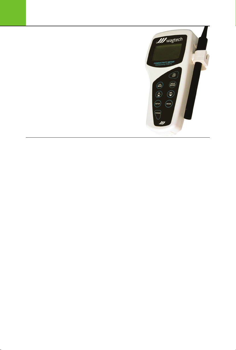
6.1 Display
The LCD has a primary and secondary display.
The primary display shows the measured pH,
mV or Relative mV values.
The secondary display shows the measured temperature.
The display also shows error messages,
keypad functions and program functions.
It has the following indicators:
1 SETUP - Setup mode
2 MEAS - Measurement mode
3 CAL - Calibration
4MR- Memory recall
5mS- milliSiemens
6µS- microSiemens
7 ppt - parts per thousand
8 ppm - parts per million
9 °C °F - Temperature mode
10 ATC - Automatic Temperature Compensation
11 ERR - Error
12 Low battery
13 Electrode status
14 Calibration solution
15 ON - READY/Auto HOLD set up enable
OFF - READY set up disable
16 K= Cell constant
17 HOLD - Hold indicator
18 READY - Ready indicator
6.2 Keypad Operation
Some buttons have several functions
depending on mode of operation.
ON/OFF - powers on and shuts off the meter.
Note: The meter will start in the measurement
mode it was in when last switched off.
• CAL/MEAS - Choose calibration
or measurement mode.
CAL - activates the pH or Relative mV
calibration mode and when used with the
MODE key, it activates the temperature
calibration mode.
MEAS - Allows return to measurement mode
when cancelling or terminating any operation.
• HOLD/ENT
HOLD - activates/deactivates freezing of the
measured reading while in measurement mode
ENTER - Confirms the calibration values and
the selection in SETUP and Print Function
mode. Scroll through the memory location
and the stored data during memory recall.
• MI (Memory Input) - Captures the measured
readings of the pH or Relative mV with
corresponding temperature, stores them
in the memory.
• MR (Memory Recall) - Retrieves the stored
data from memory.
6.0 Introduction
The Digital Conductivity Meter is part of a range of microprocessorbased instruments that are designed to be easily handled, capable
of allowing one-handed operation. Each has a large custom
dual display LCD for clear and easy reading. It is a unique and
intelligent instrument that has the capability to cater to the
preferences of the discerning individual.
The meter has many user-friendly features - all of which are
accessible through the splash-proof membrane keypad.
Your meter includes a temperature probe, electrode holder, built-in
meter stand and batteries. Palintest offers a wide selection of pH
and ORP electrodes. The advanced model is the CON 11, which
is capable of measuring Conductivity, TDS and Temperature.
For power requirements either use 4 AAA-sized batteries
or an AC/DC power adapter (sold separately).
Please read this manual thoroughly before operating your meter.
6
Digital Conductivity Meter
42

Digital Conductivity Meter
6
• Sets the calibration values during Relative mV
or Temperature calibration. Scroll through each
SETUP and its sub group menu. Scroll through
Print Function menu and its parameters.
SETUP - Activates the parameter setting menu
to allow you to customise meter configuration,
view calibration points and electrode offset
data, select auto power off, reset meter and
clear memory.
MODE - Select the measurement parameter
option between conductivity, Total Dissolved Solids
RANGE - Allows manual range selection
PRINT - Allows transfer of current measurement
or stored data to either the printer or the computer.
6.3 Meter Preparation
6.3.1 Inserting the Batteries
This meter is packaged with 4 “AAA” alkaline batteries
required for its operation. To insert the batteries into
the meter, follow the procedure outlined below.
1 Open the battery compartment by pressing
down the catch of the battery cover.
2 Insert the batteries correctly according to the
marked polarity of the battery compartment.
3 Close the battery cover, ensuring the catch
is locked in position. Your hand held meter
is now ready for operation.
6.3.2 Conductivity Electrode Information
Your meter includes a conductivity electrode.
Stainless Steel electrodes with an electrode
constant of K = 1.0. This conductivity/TDS
electrode features a built-in temperature sensor
for Automatic Temperature Compensation (ATC).
Wetted parts include:
1 Polyetherimide PEl (Ultem
2 Polybutylene Terephthalate
PST 58 (Valox
3 Stainless Steel (SS 304)
The removable protective plastic electrode guard
is meant for simple periodic maintenance and
it must be kept intact during measurement and
calibration. Always immerse the electrode beyond
upper steel band.
®
)
®
)
NOTE: DO NOT remove the protective electrode
guard during measurement and calibration as it
may affect your readings.
NOTE: We recommend that you do not submerge
the electrode above the protective yellow cap.
You can submerge the cable for brief
6.3.3 Connecting the Electrode to the Meter
1
Insert the 6 pin female connector of the electrode
to the 6 pins male connector on the meter.
Rotate the locking ring clockwise until it locks.
2 To remove the electrode, simply rotate the
connector’s locking ring counter clockwise
and pull away gently for a complete removal.
CAUTION: Do not pull on the electrode cord to
avoid internal wire breakages.
6.3.4 Attaching the Electrode
Holder to the Meter
Two electrode holders are provided:
1
Locate the slot on the right-hand side of the meter.
2 Slide the flange of the holder into the slot.
To attach a second electrode holder:
One holder can be attached onto another.
1 Align the flange of the second holder
with the slot of the first holder
2 Slide the flange of the second holder
into the slot of the first holder.
NOTE: Holders are designed for probes
12mm in diameter.
NOTE: Forcing the electrode into the opening
may damage the holder or your electrode.
6.3.5 Connecting the AC/DC Adapter
The meter can also operate on mains power
using an AC/DC power adapter (sold separately).
IMPORTANT: Switch off the meter and the
power source of adaptor before plugging in.
1 Switch off the meter and power sources.
2 Select the correct AC/DC Adaptor either at
120/220V AC (output Voltage:9 to 15V DC,
Current:>=50mA).
3 Insert the power adapter D.C. jack
into the meter power socket.
4 Switch on the power source of the
adaptor followed by the meter.
43

6
Digital Conductivity Meter
44
6.4 Calibration
Important Information on Meter Calibration:
Your meter has five measuring ranges. You have an
option of calibrating your meter in a single point
calibration for all the five ranges or for better
accuracy; you can calibrate one point in each of the
measuring ranges (up to five points). This selection
of single point calibration and multi point calibration
can be set in the SETUP menu Program P9.2.
When you perform a single point recalibration, the
old calibration will be replaced by the new one even
if the new calibration is done in a different range
from the old calibration. For example, if you have
previously calibrated at 1413µS in 0 to 2000µS
range, and you re-calibrate at 12.88 mS in 0 to
20.00 mS range, the new calibration will override
the previous calibration in 0 to 2000µS range.
In the case of multi point calibration, when you
perform a multipoint recalibration, old calibrations
are replaced only on a range basis. For example, if
you previously calibrated at 1413µS in 0 to 2000µS
range and you re-calibrate at 1500µS (also in 0 to
2000µS range), the meter will replace only the old
calibration data (1413µS) in that range.
The meter will retain all calibration data in other
ranges. To completely recalibrate your meter, or
when you use a replacement electrode, it is best
to clear all calibration data.
6.4.1 Preparing the Meter for Calibration
Before starting calibration, make sure you are in
the correct measurement mode. For best results,
select a standard value close to the sample value
you are measuring.
6.4.2 Temperature Calibration
Your electrode features a built-in temperature
sensor which is factory calibrated. Calibrate your
sensor only if you suspect temperature errors may
have occurred over a long period of time or if you
have a replacement electrode.
1 Connect the electrode.
2 Switch the meter on. ATC will appear at
the bottom right-hand corner of the LCD.
3 Press CAL/MEAS. The CAL indicator appears.
4
Press MODE to enter temperature calibration mode.
5 Dip the electrode into a solution of known
temperature (i.e. a temperature bath). Allow time
for the built-in temperature sensor to stabilise.
6 Scroll with MI/ or MR/ to set the correct
temperature value (i.e. the temperature
of the temperature bath).
7
Press HOLD/ENTER to confirm. The meter will be
calibrated and return to the measurement mode.
NOTE: To exit without confirming the
temperature calibration value, press CAL/MEAS.
NOTE: If the ATC does not light up, see SETUP
menu Program P1.3 to switch it on.
NOTE: Since temperature affects the accuracy of
conductivity/TDS, it is recommended to carry out
a conductivity/TDS calibration after a temperature
calibration is done.
6.4.3 Automatic or Manual, Single
or Multi point Calibration (P9.0)
Choose automatic conductivity calibration or manual
conductivity/TDS calibration. In the automatic
calibration mode, the meter automatically detects
and verifies the appropriate known calibration
standards solutions before accepting these particular
calibration standards as one of its calibration
values in a specific measurement range.
The known calibration standards used for
automatic calibration are:
At 25.0°C: 841µS, 14131µS, 12.88mS, 111.8mS
At 20.0°C: 761µS, 12781µS, 11.67mS, 102.1mS
In the manual calibration, non-standard
calibration values can be used. You can manually
input the appropriate values as your desired
calibration standards in each specific range.
6.4.4 Selection of Automatic
or Manual Calibration (P9.1)
Automatic calibration is applicable in conductivity
measurement mode only, manual calibration is
applicable in both conductivity and TDS mode.
Only from the conductivity measurement mode;
1 Press SETUP.
2 Press MI/ or MR/ until you
view parameter P9.0 (ASC).
3 Press HOLD/ENTER. The upper
display will show “ACA”.

Digital Conductivity Meter
6
4 Press HOLD/ENTER
5 Press MI/ or MR/ to select. “YES”
activates automatic calibration,
“NO” activates manual calibration.
6 Press HOLD/ENTER to confirm.
7 Press CAL/MEAS key twice to
return to measurement mode.
NOTE: Parameter P9.1 will only be in the Set Up
menu if you enter from the conductivity measurement
mode. If you enter from the TDS measurement
mode, Parameter P9.1 will not be displayed.
6.4.5 Selection of Single or
MultiPoint Calibration (P9.2)
Single point calibration lets you have a single
calibration factor for all five ranges by calibrating
one point in either one of the ranges, this factor
is applied to all the five ranges.
Multi point calibration gives better calibration
accuracy by letting you calibrate in each of the
five ranges, this calibration factor would only be
applicable in the particular range where the
calibration is done.
1 Press SETUP.
2 Press MI/ or MR/ until you
view parameter P9.0 (ASC).
3 Press HOLD/ENTER. The upper
display will show “SPC”.
4 Press HOLD/ENTER.
5 Press MI/ or MR/ to select. “YES”
activates single point calibration,
“NO” activates multi point calibration.
6 Press HOLD/ENTER to confirm.
7
Press CAL/MEAS to return to measurement mode.
6.4.6 Automatic Calibration
(For Conductivity Calibration Only)
This procedure describes the method for
calibration to a 1413µs calibration standard.
NOTE: Select automatic or manual calibration
as described in Selection of Automatic or
Manual Calibration.
NOTE: Select single -or multi point calibration
as described in Selection of Single or MultiPoint
Calibration (P9.2).
NOTE: To exit without confirmation, press
CAL/MEAS to go back to measurement mode.
1 If necessary, press MODE to select
conductivity mode.
2 Rinse the electrode with deionised water
or a rinse solution, then rinse with a small
amount of calibration standard.
3 Dip the electrode into the calibration standard.
Immerse the electrode tip beyond the upper
steel band. Stir the electrode gently to create
a homogeneous sample. Allow time for the
reading to stabilise.
4 Press CAL/MEAS to enter calibration mode.
The CAL indicator will appear in the upper
corner of the display. The primary display
shows the current measured value, the
secondary display shows the calibration
standard value.
5 Press HOLD/ENTER to confirm. The meter will
now return to the measurement mode. Multi
point calibration: repeat step 1 to 5 for every
calibration point in each measuring range
using the known calibration solutions until
all points have been calibrated.
6.4.7 Manual Calibration
(For Conductivity & TDS Calibration)
This procedure describes calibration to
a 12.00mS calibration standard.
NOTE: Select automatic or manual calibration as
described in Selection of Automatic or Manual Calibration.
NOTE: Select single -or multi point calibration as
described in Selection of Single or Multipoint Calibration.
NOTE: To exit without confirmation, press
CAL/MEAS to go back to measurement mode.
1 Repeat step 1 to 4 from Automatic
Calibration.
2 Wait for the value to stabilise and press.
MI/ or MR/, adjust the value in the upper
display to the calibration standard used.
3 Press HOLD/ENTER to confirm and return to
measurement mode. Multi point calibration:
repeat step 1 to 6 for every calibration point
in each range using the calibration solutions
until all points have been calibrated.
45

6
Digital Conductivity Meter
46
6.4.8 TDS Calibration
Calibrating TDS with conductivity standards &
adjusting TDS factor Instead of calibrating for TDS
directly using TDS calibration standard solutions,
you can calibrate by using the conductivity
calibration method and enter the appropriate
TDS conversion factor into the meter.
6.4.9 Setting the TDS Conversion Factor
The factory default setting for TDS conversion
factor is 0.5. If your solution has a different TDS
factor, you can improve accuracy by setting the
TDS factor prior to calibration.
1 Press MODE to select TDS mode.
2 Press Setup.
3 Press HOLD/ENTER five times
to scroll until you view P1.4 (tdS).
4 Press HOLD/ENTER. The upper display
shows a value and the lower shows “tdS”.
5 Press MI/ or MR/ to select your
calculated TDS conversion factor.
6 Press the HOLD/ENTER key to confirm.
7 Press the CAL/MEAS key to
return to measurement mode.
6.4.10 Calibrating for TDS using TDS Standards
After setting the correct TDS Factor, you can
calibrate in the TDS mode.
1 Press MODE to select the TDS mode.
2 Follow the instructions in Manual Calibration
for the rest of the calibration process, this
time using the TDS calibration standards.
NOTE: You can offset the TDS reading up to ±
40% from the default setting. If your measured
value differs by more than ± 40%, clean or
replace electrode as needed.
6.5 Measurement
6.5.1 Temperature Compensation
This meter can take measurements with automatic
(ATC) or manual (MTC) temperature compensation.
Factory default is ATC on. For ATC, attach the
conductivity/TDS electrode to the meter. The ATC
indicator will light on the LCD. If the conductivity/
TDS electrode is not properly attached to the meter
or it has been damaged, the ATC indicator will blink
and the temperature display will show ‘Ur’. If the ATC
indicator does not light and the temperature display
shows a reading, the meter might be in MTC mode.
6.5.2 Selecting Temperature
Compensation mode
1 Press SETUP
2 Press HOLD/ENTER 3 times to
scroll until you view P1.3 (AtC)
3 Press HOLD/ENTER. The upper display shows
“ATC” and the lower display shows “YES”.
4 Press MI/ or MR/ to select: ‘YES’,
ATC is on or ‘NO’, ATC is off.
5 Press HOLD/ENTER to confirm selection.
6
Press CAL/MEAS to return to measurement mode.
6.5.3 Setting Manual
Temperature Compensation Value
MTC enables you to enter the temperature value of
your sample into the meter. This is the value at which
the readings will be temperature compensated.
1 Set temperature mode to MTC
and go through step 1 to 6.
2 Press CAL/MEAS. The CAL indicator
will appear above the primary display.
3 Press MODE.
4 Press MI/ or MR/ to offset the
temperature to your preferred settings.
5 Press HOLD/ENTER to confirm
NOTE: To exit this program without confirming
the MTC value, press CAL/MEAS.
6.5.4 Taking Measurements
1
Rinse the electrode with deionised or distilled water
before use. Shake or air dry. To avoid contamination
or dilution of your sample, rinse electrode
with a small volume of your sample liquid.
2 Press ON to switch on meter.
3 Dip the electrode into the sample. When
dipping the electrode into the sample, ensure
that the liquid level is above its upper steel
band. Stir the electrode gently in the sample
to create a homogenous sample.
4 Allow time for the reading to stabilise.
5 Press MODE to toggle between conductivity
and TDS readings (if necessary).

Digital Conductivity Meter
6
6.5.5 HOLD Function
Let’s you freeze the display and hold the
measured value.
1 Press HOLD/ENTER to hold a measurement.
‘HOLD’ will appear on the display.
2 Press HOLD/ENTER again to
release the held value.
NOTE: If the meter is shut off the HOLD value will be
lost. For longer storage, use the memory functions.
6.5.6 Selection of READY (P1.1)
The ‘READY’ display indicates the measurement
stability during a measuring process.
From measurement mode:
1 Press SETUP.
2 Press HOLD/ENTER.
3 Press MI/ or MR/ to select the
configuration you require (left display).
a. ‘ON’ activates the READY function.
b. ‘OFF’ deactivates the READY function.
4 Press HOLD/ENTER to confirm selection.
5 Press CAL/MEAS twice to return
to measurement mode.
6.5.7 Range Setting and Option
Your meter automatically selects the range
in which your readings appear.
The manual ranging function lets you select
the specific range you want to work in.
6.5.8 Selecting Manual or Auto Ranging
1 Press RANGE while in measurement mode.
Display will show either ‘r1’ to ‘r5’, indicating
the range you are in. The range selected will
appear and ‘MEAS’ blinks.
2 Press RANGE, until desired range is selected.
Digital Conductivity Meter 65
3 To re-select the auto-ranging, repeatedly
press RANGE until ‘MEAS’ stops blinking.
NOTE: If the measured value is higher than the
range selected, ‘Or’ will appear. Press RANGE
until the correct range is selected.
NOTE: The meter resets to the Autoranging once
it is turned off. Manual ranging needs to be reset
each time you turn the meter on.
6.6 Memory Function
The CON 11 meter stores up to 50 set of data
respectively. Data sets include conductivity, TDS
and temperature values.
6.6.1 Memory Input
Press MI/ during measurement to input data into
the memory. MEM, “StO” and memory number
will appear for a moment.
If necessary, measure the next sample solution and
press Mil key to input the next data into the memory.
NOTE: If the memory is full, the display will
flash “FUL” momentarily. The first value stored
will be overwritten.
6.6.2 Memory Recall
Press MR/ once to retrieve the last reading stored.
1
2 Press HOLD/ENTER to recall the reading.
3 Press HOLD/ENTER to return. The display
automatically moves to the next memory
location screen.
4 Press MI/ or MR/ to scroll to a specific memory
location, press HOLD/ENTER to select.
5 Press CAL/MEAS to exit Memory Recall.
NOTE: Readings stored in memory are
retained even if the unit is turned off.
6.6.3 Memory Clear (P6.0)
1 Press SETUP.
2 Press MI/ (5x) or MR/ (4x) until
you view the parameter P6.0 (CLr).
3 Press HOLD/ENTER.
Press MI/ or MR/ to toggle between NO and YES.
4
‘NO’ retains current memory, ‘YES’ clears
all memory.
5 Press HOLD/ENTER to confirm selection.
Press CAL/MEAS to return to measurement mode.
6
6.7 Other Functions
6.7.1 Viewing calibration data (P2.0)
1 Press SETUP.
2 Press MI/ (1x) or MR/ (8x) until
you view parameter P2.0 (CAL).
3 Press HOLD/ENTER repeatedly to view the
previous calibration data on each of the five
measuring ranges.
47

6
Digital Conductivity Meter
48
4 When you have scrolled through all
calibration data, you will automatically
return to the subgroup menu.
5 Press CAL/MEAS key to return
to the measurement mode.
NOTE: If there is no calibration data at a particular
point, the primary display will show “----”.
6.7.2 Viewing Electrode Data (P3.0)
1 Press SETUP.
2 Press MI/ (2x) or MR/ (7x) until
you view parameter P3.0 (ELE).
3 Press HOLD/ENTER repeatedly to view
the effective cell constant for each range.
4 When you have scrolled through all the
electrode data, you will automatically
return to the subgroup menu.
5
Press CAL/MEAS to return to measurement mode.
6.7.3 Auto Off (P4.0)
You can activate the Auto Off option to
automatically switch off the instrument 20
minutes after the last key selection.
1 Press the SETUP key to enter Set Up mode.
2 Press MI/ (3x) or MR/ (6x) until
you view parameter P4.0 (AtO).
3 Press HOLD/ENTER.
4 Press MI/ or MR/ to select: YES -
activates the Auto Off function or NO deactivates the Auto Off function.
5 Press HOLD/ENTER to confirm
and return to subgroup menu.
6 Press the CAL/MEAS key to
return to measurement mode.
6.7.4 Reset to factory defaults (P5.0)
Either reset calibration data only (P5.1 CAL)
or reset all to factory default (P5.2 Usr).
6.7.5 Calibration Reset (P5.1)
1 Press SETUP.
2 Press MI/ (4x) or MR/ (Sx) until
you view parameter P5.0 (rSt).
3 Press HOLD/ENTER.
4 Press HOLD/ENTER.
5 Press MI/ or MR/ to select: NO retains current
settings or YES clears all calibrations and its data.
6 Press HOLD/ENTER to confirm
and return to subgroup menu.
7
Press CAL/MEAS to return to measurement mode.
6.7.6 User Reset (P5.2)
1 Repeat step 1 to 4
2
Press HOLD/ENTER to enter parameter P5.2 (Usr).
3 Press HOLD/ENTER
4 Press MI/ or MR/ to select: NO retains current
settings or YES resets to factory default settings.
5 Press HOLD/ENTER to confirm
and return to subgroup menu.
6
Press CAL/MEAS to return to measurement mode.
6.7.7 Setting the
Temperature Coefficient (P7.1)
The temperature coefficient is the amount
of change in conductivity per degree of
temperature; it is expressed in percent per DC.
Entering the exact temperature coefficient of
your solution lets you accurately compensate
temperature for almost any solution. You can
adjust 0.0 to 10.0% per DC.
Meter default is 2.1% per DC. By setting the
temperature coefficient to 0.0%, the meter will
not apply any compensation but will display
actual temperature.
1 Press SETUP.
2 Press MI/ (6x) or MR/ (3x) until
you view parameter P7.0 (tPr).
3 Press HOLD/ENTER.
4 Press HOLD/ENTER.
5 Press MI/ or MR/ to select the
temperature coefficient of your solution.
6 Press HOLD/ENTER to confirm
and return to subgroup menu.
7 Press CAL/MEAS twice to return
to the measurement mode.

Digital Conductivity Meter
6
6.7.8 Setting the Normalisation
Temperature (P7.2)
Your meter will normalise its conductivity
measurements to a standard temperature that
you can select. You can adjust the normalisation
temperature either at 20.0°C or 25.0°C. Meter
default is 25.0°C.
1 Repeat step 1 to 4
2 Press HOLD/ENTER.
3 Press HOLD/ENTER.
4 Press MI/ or MR/ to select either 20.0°C or
25.0°C as the normalisation temperature.
5 Press HOLD/ENTER to confirm
and return to subgroup menu.
Press CAL/MEAS to return to measurement mode.
6
6.7.9 Selection of Cell Constant (P8.0)
The meter lets you select a cell constant of
K = 1.0, 10, or 0.1. The cell included with
your meter has a cell constant of K=1.0.
1 Press SETUP.
2 Press MI/ (7x) or MR/ (2x) until
you view parameter P8.0 (CEl).
3 Press HOLD/ENTER.
4 Press MI/ or MR/ to select the cell
constant between K = 1.0, 0.1, or 10.
5 Press HOLD/ENTER to confirm selection
and return to the subgroup menu.
6 Press CAL/MEAS to return to
measurement mode.
6.8 Error Messages and Troubleshooting
Error message/Problem Possible Cause Corrective Action
Err. Annunciator Wrong input in
Secondary Display toggles
continuously between
Calibration Standard Values
Battery icon illuminated Low battery
Blank display when
ON/OFF key is selected
Unstable reading 1 Air bubbles in electrode
Slow response Dirty/oily electrode Clean electrode
Meter not responding to key press HOLD mode in operation Cancel HOLD mode
ATC indicator blinks and
temperature shows “Ur”
selected mode
Incorrect solution used in
calibration or contaminated
calibration solution
1 Batteries not in place
2 Batteries not aligned
to correct polarity
3 Low level batteries
No AC power to adapter (if used)
4
2 Dirty electrode
3 Electrode not deep
enough in sample
4 External electrical noise
caused by nearby motor
5 Electrode guard not attached
1 Improper attachment
of electrode to meter
2 Electrode temperature sensor
cable connection has broken
Release key. Select valid
operations depending on mode
Check if correct solution used,
replace with fresh solution if
where necessary
Replace with new batteries as soon as possible
1 Insert batteries
2 Insert batteries to correct polarity position
3 Replace batteries or connect to AC adaptor
4 Check power supply to AC adaptor
1 Tap electrode to remove bubbles. Reposition
electrode away from bubbles in sample
2 Clean electrode and recalibrate
3 Immerse electrode to cover electrode sensors
4 Move location or switch off interfering device
5 Attach guard
1 Check that the electrode is
properly connected to the meter
2 Replace electrode
49

6
Digital Conductivity Meter
50
Conductivity Range 0 - 19.99; 20.0 - 199.9; 200 - 1999 µS/cm; 2.00 - 19.99; 20.0 - 199.9 mS/cm
TDS Range
0.00 to 9.99 ppm; 10.0 to 99.9 ppm; 100 to 999 ppm; 1.00 to 9.99 ppt; 10.0 to 99.9 ppt
Resolution 0.05% Full Scale
Accuracy ±1% F.S. +1 digit
Temperature Range -10.0 to 110.0°C
Temperature Resolution 0.1°C
Temperature Accuracy ± 0.5°C
Temperature Compensation Automatic/Manual (from 0 to 100°C)
Temperature Coefficient 0.0 to 10.%/°C
TDS Factor 0.40 to 1.00
Calibration Points (Automatic) 84.0, 1413µs/cm; 12.88, 111.8mS/cm
Calibration Points (Manual) User defined standard/1 per range up to 5 points
Single/Multi point calibration Selectable
Calibration Range 10% to full scale
Auto-ranging Yes (manual select available)
HOLD Function Yes
Memory 50 Data Sets 100 Data Sets
RS232 Yes No
Auto Off Selectable
Auto Off Time 20 minutes after last key operation
Meter Warranty 3 years
6.9 Technical Specification

7.0 Introduction
The Digital Arsenator is
designed for field or laboratory
determination of Arsenic
in the range 2-100µg/l As.
Using the modified Gutzeit
method and the unique
tri-stage filter assembly,
the Digital Arsenator will
provide accurate and safe
measurement of Arsenic.
7.1 Operating Method
1 Take the tri-filter assembly and load a Hydrogen
Sulphide filter in the base of the assembly.
Digital Arsenator
4 Switch the Arsenator on by pressing any key.
7
2 Take a red filter paper holder and
load with a destruction paper.
3 Take a black filter paper holder
and load with a detection paper.
5
Place the loaded black filter paper holder into the
Arsenator to blank and start the 20 minute timer.
6 Load the tri-filter
assembly with the
red and black filter
paper holders.
51

7
Digital Arsenator
52
7
Add 50ml of sample and add to the conical flask.
8 Add the contents of the A1 (Sulphamic Acid)
sachet and swirl to dissolve.
9 Drop one A2 tablet into the flask.
NOTE: the sample will fizz significantly.
Immediately insert the tri-filter assembly into the
conical flask neck to prevent any Arsine gas escaping.
10 Wait for 20 minutes for reaction
to proceed to completion.
11 Upon completion, insert the black filter
paper holder into the Arsenator and
the result will be displayed in µg/l.
12 Results higher than 100µg/l will
require the colour comparison chart
to determine the approximate value.
13 For more accurate results dilute
the sample and repeat the testing.
14 Dispose of used materials carefully
- they may contain Arsenic.
Hints and Tips
• Never use a broken filter paper holder - the seal
will not be gas tight and results will be affected.
• Never insert the red filter paper
holder into the Arsenator.
• Insert filter paper holders fully
for maximum sensitivity.
• Replace the Hydrogen Sulphide
filter when it is completely black.
• If low battery is shown on the Arsenator,
replace the battery within 10 tests.
Measurement Range 2 to 100µg/litre
Test Duration 20 minutes
Power Requirements 1 x 9V battery
Dimensions 127 x 115 x 40mm
Weight 220g
7.2 Technical Specification

Appendix 1 - Reagents and Consumables
Part Number Description
APW 152 Ammonia, 200 tests, Polypropylene Carton
APW 179 Fluoride, 200 tests, Polypropylene Carton
APW 031 Free and Total Chlorine (DPD 1 & 3), 250 tests, Polypropylene Carton
APW 163 Nitrate (Nitratest), 200 tests, Polypropylene Carton
APW 109 Nitrite (Nitricol), 200 tests, Polypropylene Carton
AP 152 Ammonia, 200 tests, Refill Pack
AP 179 Fluoride, 200 tests, Refill Pack
AP 031 Free and Total Chlorine (DPD 1 & 3), 250 tests, Refill Pack
AP 163 Nitrate (Nitratest), 200 tests, Refill Pack
AP 109 Nitrite (Nitricol), 200 tests, Refill Pack
PT 595/5 Photometer cuvettes, pack of 5
PT 663 Cuvette Brush
PT 502 Crush/Stir Rods, pack of 10
PT 512 Dilution Tube/Sample Tube
66103485 Black Arsenic Filter Papers, 400 pack
66103486 Red Arsenic Filter Papers, 200 pack
66104155 A1 Powder (Sulphamic Acid), 200 sachets
66109647 A2 Tablets (Sodium Borohydride), 4 pots of 50
66103651 Hydrogen Sulphide removal filters, 5 pack
PTC 090 Compact Turbimeter Calibration Set
PT 121 4000 NTU Formazin Standard, 100mls
PT 555 Turbimeter cuvettes with caps, pack of 5
PT 120 Silicone Oil, 10mls
PT 142/15 pH 4 buffer solution, 60mls
PT 142/12 pH 7 buffer solution, 60mls
PT 142/13 pH 10 buffer solution, 60mls
PT 142/7 Conductivity solution, 60mls
8
53

Palintest Ltd
Palintest House, Kingsway, Team Valley,
Gateshead, NE11 0NS
Tel: +44 (0)191 491 0808
Fax: +44 (0)191 482 5372
sales@palintest.com (UK)
export@palintest.com (International)
Palintest Australia and Asia Pacific
1/53 Lorraine Street,
Peakhurst Business Centre,
Peakhurst, NSW 2210, Australia
Tel: +61 1300 131516
Fax: +61 1300 131986
palintest@palintest.com.au
Palintest USA
1455 Jamike Avenue (Suite 100),
Erlanger, Kentucky, 41018, USA
Tel: +1 859 341 7423
Toll Free: 800 835 9629
Fax: +1 859 341 2106
info@palintestusa.com
Palintest China
Room 1711, Fanli Mansion,
22 Chaowai Street, Chaoyang District,
Beijing, 100020, PRC
Tel: +86 10 6588 6200
Fax: +86 10 6588 8311
china@palintest.com
Palintest Middle East
PO Box 27709, Engomi 2432,
Nicosia, Cyprus
Tel: +357 226 66080
Fax: +357 226 60355
sales@palintest.me
ZI PTW 10010C
 Loading...