

Palec Paton Electrical V.C.T. Instruction Manual
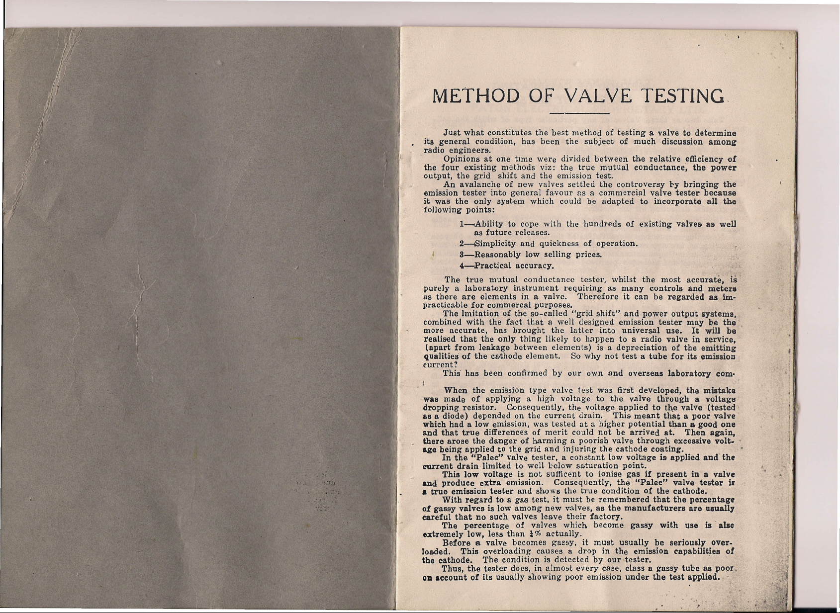
METHOD OF VALVE TESTING.
J1ust what constitutes the best method of testing a valve to determine
its general condition, has been the subject of much discussion among
radio engineers.
Opinions at one
the four existing methods viz: the true mutual conductance, the power
output, the grid shift and the emission test.
An avalanche of new valves settled the controversy 1>ybringing the
emission tester into general favour as a commercial valve tester because
it was the only system which could be adapted to incorporate all the
following points:
l---.Ability to cope with the hundreds of existing valves as well
as future releases.
2--Simplicity and quickness of operation.
S-Reasonably low selling prices.
4--.Pract.ic~1 accuracy.
The true mutual conductance tester. whilst the most accurate,
purely a laboratory instrument requiring as many controls and meters
as there are elements in a valve. Therefore it can be regarded as im-
practicable for commercal purposes.
The Imitation of the so-called "grid shift," and power output systems,
combined with the fact that a well designed emission tester may ~e the
more accurate, has brought the latter into universal use. It will be
realised that the only thing likely to happen to a radio valve in service,
(apart from leakage between elements) is a depreciation of the emitting
qualities of the ell-thode element. So why not test a tube for ita emissioD
current?
This' has been confirmed by our own and overseas laboratory eom-
time
were divided between the relative efficiency of
IS
-
,
~
.~
When the emission type valve test was first developed, the mistake
was made of applying a high voltage to the valve through a voltage
dropping resistor. Consequently, the voltage applied to the valve (tested
as a diode) depended on the current drain. This. meant that a poor valve -
which had a low emission, was tested at a higher potential than a. good one
and that true differences of merit could not be arrived at. Then a&ain,
there arose the danger of harming a poorish valve through excessive vol~ .
age being applied to the grid and injuring the cathode coating.
In the "Palec" valve tester, a constant low voltage is applied and th.
current drain limited to well below satura tion point. _
This low voltage is not sufficent to ionise gas if present in a valve
and produce extra emission. Consequently, the "Palec" valve tester ir
a true emission tester and shows the true condition of the cathode.
With regard to a gas test, it must be remembered that the percentage
of gassy valves is low among new valves, as the manufacturers are UlualJ,
careful that no such valves leave their factory.
The percentage of valves which become gass'y with use is' alao
extremely low, Iess than
Before a valve becomes gassy, it must usually be seriously over-
loaded. This overloading causes a drop in the emission rapabilitiea of
the cathode. The condition is detected by our-tester.
Thus, the tester does, in almost every caee, class a gasSy tube as poor.
Oil account of its usually showing poor emission under the test applied.
z
%
actually.
,
.
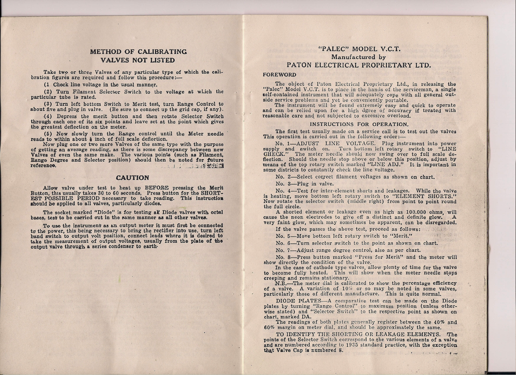
METHOD OF CALI
BRA
TING
VALVES NOT USTED
Take tw~ or three Valves of any particular type of which the cali-
bration figures are required and follow this procedure:-
(1 Check line voltage in the usual manner,
(2) Turn Filament Selector Switch to the voltage at wlJch the
particular tube is rated.
(3) Turn left bottom Switch to Merit test, turn Range Control to
about five and plug in valve. (Be sure to connect up the grid cap, if any).
,(4) Depress the merit button and then rotate Selector Switch
through each one of its six points and leave set at the point which gives
the greatest deflection on the meter.
(5) Now slowly turn the Ra.nge control until the Meter needle
reads to within aboutiinch of f,ull scale deflection.
Now plug one or two more Valves of the same type with the purpose
of getting an average reading, as there is some discrepancy between new
Valves of even the same make. The va.rious points (such aa Filament,
Range Degree and Selector position) should then be noted for ~ture
reference. , , :,
"I
,~_"~jjdl~:rli,Z1
CAUTION
Allow valve under test to heat up B·EFO.RE pressing the Merit
Button, this usually takes 30 to 60 seconds, Press button for the SHORT-
EST POSSIBLE PERIOD necessary to take reading. This instructio.
ahould be applied to all va.lves, particularly diodes.
The soeketjmarked "Diode" is for testing a£ Diode vl>lves with octal
ba.ses, test to be carried out in the same manner aa all other valveIJ.
To use the instrument as r.n output meter it must
to the power, this being necessary, to bring the rectifier into use, turn left
hand switch to output volt position, connect leads where it is desired to
tr.ke the measurement of output voltages, usually from the plate of tlhe
output valve through a series condenser to earth·
first
be connected
r .•
"PALEC" MODEL V.C.T.
Manufactured
by
PATON ELECTRICAL PROPRIETARY LTD.
FOREWORD
The object of Paton Electrical Proprietary Ltd., in releasing the
"Palec" Model V.C.T. is to place in-the hands of the serviceman, a single
self-contained instrument that will adequately cope with all general out-
side service problems and yet be conveniently portable.
The instrument will be found extremely easy and quick to operate
and can be relied upon for a high dgree of accuracy if treated with
reasonable care aJilq not subjected to excessive overload.
INSTRUCTIONS FOR OPERATION.
The first test usually made on a service call is to test out the valves
This operation is carried out in the following order;-
No.1-ADJUST LINE VOLTAGE. Plug instrument into power
supply and switch on. Turn bottom left rotary switch to "LINE
GHECK." The meter needle should now swing over to full scale de-
flection. Should the needle stop above
means of the top rotary switch marked "LINE ADJ." !tis important in
some districts to constantly check the line voltage.
No. 2-Select correct filament voltages as shown on chart.
No.3-Plug in valve.
No. 4-T,est for inter-element shorts and leakages. \Vhile the valVe
is heating, move bottom left rotary switch to "ELEMENT SHORTS."
Now rotate the selector switch (middle. right) from point to point round
the full circle.
A shorted element or leakage even as high as 100.000 ohms will
cause the neon electrodes to give off a distinct and definite glow.' A
Tery faint glow, which may sometimes be apparent, can be disregarded,
If the valve passes the above test, proceed as follows: , , "
No.5-Move bottom left rotary switch to "Merit."
No.6-Turn selector switch to the point as shown. on
No.7-Adjust range degree control, also as per
No.8-Press button marked "Press for Merit" and the meter will
show directly the condition of the valve.
In the case of cathode type valves, allow plenty of time for the valve
to become fully heated, This will
creeping and remains stationary. ' .
N.B.-The meter dial is calibrated to show the percentage efficiency
of a valve. A variation of 10
particularly those of different manufacture. This is quite normal.
DIODE BLATES-A comparative test can be made on the Diode
plates by turning "Range Control" to maximum position (unless other-
wise stated) and "Selector Switch" to the respective point as shotwn on
chart, marked DA.
The readings of both plates generally register between the 40% and
60-% margin on meter dial, and should be approximately the same.
TO IDENTIFY THE SHORTING OR LEAKAGE ELEMENTS. lThe
points of the Selector Switch correspond to the various elements of a valve
and are numbered according to 1935 standard practice, with the exception
that Valve Cap ia numbered 8. '
,:.c
01'
below this position, adjust
chart,'
chart;
sho-w
when the meter needle stops
01'
so may be noted in some valves,
,I ";~
•• r
c,
I,''''
by
,J
 Loading...