


Manual Instruction
Model 151
April 2005
palamides GmbH
Benzstraße 14 – 71272 Renningen
Tel: +49 (0) 7159 / 92570-0 – Fax +49 (0) 7159 / 92570-99
www.palamides.de
1

2

Contents
How it works......................................................................................................................7
1
2 Technical Data ..................................................................................................................9
3 Fundamental Safety Advice ............................................................................................11
4 Machine installation.........................................................................................................13
5 Description of the machine parts.....................................................................................16
6 Handling and Operation ..................................................................................................20
7 Setting up the machine....................................................................................................27
8 Optimisation menu ..........................................................................................................43
9 Quick set-up....................................................................................................................46
10 Quick Check....................................................................................................................47
11 Sensors, Pneumatics, Motors .........................................................................................49
Subject to change without notice
3

1
4
Subject to change without notice

How it works
We
Hereby declare that because of their design and construction, the machinery/devices
detailed below comply with the Health and Safety legislation of the EC-Machinery Directive.
This Declaration becomes invalid if an alteration is made which has not been agreed with
ourselves.
Product Automatic Delivery delta
1
Declaration of Conformity
Manufacturer Declaration
according to EC-Machinery Directive 98/37/EG, Annex II A
palamides GmbH
Benzstr. 14
71272 Renningen/Germany
Model 151, 152, 153
Serial number
Appropriate EC-Directives:
EC-Machinery Directive (98/37/EG)
EC-Low Tension Directive (73/23/EWG)
To comply the basic requirements we consulted the following appropriate standards:
EN 12100-1; EN 12100-2; EN 294
pr EN 1010 EN 60204-1
Date 16.10.2006
Signature (S. Palamides)
Identification of the
Signatory Managing Director
Sous réserve de modifications
5

1
How it works
Preface
You have acquired a technically superior industrial product in the delta automatic delivery
and by paying careful attention to the operating instructions, you will achieve the highest
levels of reliability and performance.
The delta is a fully automatic delivery system, which greatly rationalises the production
process behind the folding machine or saddle stitcher. Depending on the model, up to 5-up
work can be simultaneously processed in a very wide format range.
Sophisticated technical detailed solutions are responsible for the outstandingly high
production reliability. All sheets are measured at the infeed and, if necessary, are ejected.
The pile is bundled directly in the collection shaft using the patented operating process which
has been implemented in the delta.
Here, the most important aspect is not the bundling of the packages, but the rationalisation
achieved. By using a delta, one person can operate a folding machine rather than 2-3. With a
saddle stitcher, the work can easily be taken off the machine by the same operators who
load it.
• Rationalisation of the delivery process on saddle stitchers and folding machines.
• Makes use of the top running speed and performance of the producing machines
• Short setting-up times
• High efficiency due to the versatile application possibilities and the large format
range
• Pays for itself quickly
• Mark-free delivery (no smearing on freshly printed or sensitive sheets)
• Integrated pressing unit with main and pre-press rollers
• Ergonomically convenient working height for removing bundles
• By using different coloured bands per up-work, different versions (e.g. language
versions) can be easily distinguished.
These operating instructions should guide you in operating the stacking delivery correctly, in
complying with the safety regulations and in servicing the machine properly.
6
Änderungen vorbehalten

How it works
1 How it works
1.1 Area of application
The delta automatic delivery is primarily a fully automatic delivery system which greatly
rationalises the production process after a folding machine or saddle stitcher. The products
are counted and bundled in easily handled piles. Products such as advertising brochures,
mailings and signatures can be processed.
1.2 How it works
The delta automatic delivery is a fully automatic delivery system for cost-effective packaging
of pamphlets, signatures and brochures. Up to 5-up in a very large format range are
processed simultaneously. The exceptionally high production reliability is achieved through
sophisticated detailed solutions. As a result, all sheets are measured at the infeed and, if
necessary, ejected. The pressing unit, which is fitted as standard, together with the jogging
device, ensures that pile formation is neat and reliable. The pile is bundled directly in the
collection shaft using the patented operating process which has been implemented in the
delta. No slipping in the pile, whether unstable products or the smallest package, the delta
bundles reliably. Bundling is carried out using a choice of coated Kraft paper or PE film in
easily changeable magazines. The bundled packages are laid out on a package lift, which
conveys the packages to an ergonomically convenient working height.
1
Standard equipment
ELECTRONIC FORMAT MONITORING WITH WASTE SHEET DEFLECTOR
Incorrectly folded products are ejected.
ELECTRONIC CONNECTION TO MBO FOLDING MACHINES
Connection to the start/stop function, as well as the sheet call-up function
(24-pin design).
ELECTRONIC SHEET COUNTER
Counts the products irrespective of the production machine.
EQUIPMENT FOR PROCESSING MULTIPLE UP-WORK
delta up to 5-up, depending on model.
PRESSING DEVICE
Maximum 3.5t with pre and main pressing rollers.
Subject to change without notice
7

1
How it works
Options
SMALL FORMAT DEVICE
For processing products up to 90mm x 65mm.
STACKING LEVEL COMPENSATION 70MM
For forming tidy piles of spine stitched brochures and 4-sided folded products.
STACKING LEVEL COMPENSATION 150MM
For products which spread out heavily at the binding edge.
ANTISTATIC DEVICE
For improved processing of products laden with static.
AIR BLAST DEVICE
For smooth processing of difficult products on
Saddle stitchers and from layered folding.
SMALL PACKAGE DEVICE
For creating packages with a pile height of less than 20 mm
SADDLE STITCHER CONNECTION
For operation with saddle stitchers. An appropriate saddle stitcher plug to be
provided by the customer.
NAVIGATOR INTERFACE
For operation after MBO folding machines with Navigator control.
STAHL INTERFACE (10-PIN)
For operation after Stahl folding machines with 10-pin plug.
STAHL DIGITAL INTERFACE
For operation after Stahl digital folding machines
(only in connection with a 10-pin Stahl interface).
BARCODE RECOGNITION
For postcode sorting or for the collating function on digital printing machines.
PRINTER’S IMPRINT READER
For reliable separation of single book blocks in book-on-demand lines
CARD INSERTER
To supply a card for the upper and lower side of the pile, which is bundled with it.
8
Subject to change without notice

Technical Data
2 Technical Data
2.1 Formats
2
Minimum format
(without small package device)
Minimum format
(with small package device)
delta502
Infeed width x Infeed length
110mm x 95 mm
90 mm x 65 mm
max. for 1-up 510 mm x 305 mm
max. for 2-up 235 mm x 305 mm
delta703
max. for 1-up 760 mm x 305 mm
max. for 2-up 335 mm x 305 mm
max. for 3-up 235 mm x 305 mm
delta705
max. for 1-up 760 mm x 305 mm
max. for 2-up 335 mm x 305 mm
max. for 3-up 235 mm x 305 mm
max. for 4-up 175mm x 305 mm
max. for 5-up 148 mm x 305 mm
min. package height (without small package device) 20mm
min. package height
max. package height (
with small package device) 3mm
depends on product ) 150 mm
Performance Over 600 Packages/h per up-work
Over 60.000 Products/h per up-work
product)
(depends on
Speed 15-200m/min
Subject to change without notice
9

2
Technical Data
Noise level, measured according to EN 13023:2003 does not exceed 83dB(A)
(Measuring device B&K, Type 2221, Serial no. 16 95 9 64, microphone type
4176, no. 1718861, accuracy class 1, acoustic calibrator type 4230, serial no.
1678942
2.2 Connections
Elec. connection 6 KW
Compressed air
consumption
The supply of purified, dry compressed air (6 bar) is not included in delivery.
delta layout
350 ltr/min net, 6 bar, dry, filtered air supplied by the
customer
10
Subject to change without notice

Fundamental Safety Advice
3 Fundamental Safety Advice
3.1 Warning advice and symbols
This symbol means immediate, imminent danger to a person's life or health.
!
DANGER
!
WARNING
!
CAUTION
Ignoring this warning results in severe consequences for a person's health,
up to critical injury.
This symbol means possible, imminent danger to a person's life or health.
Ignoring this warning results in severe consequences for a person's health,
up to critical injury.
This symbol means a possible dangerous situation.
Ignoring this warning results in severe consequences for a person's health
and / or damage to property.
3
3.2 Permitted use
The "delta" Automatic Delivery intended solely as a delivery for folded brochures and spine
stitched brochures in paper processing companies. Any other or any additional use is not
regarded as a permitted purpose. “Palamides” is not liable for any damage arising from this.
3.3 Safety at work
1. At the time of supply, “palamides” Automatic Deliveries meet all safety-related
regulations. For this purpose, moving and rotating parts are covered with safety hoods,
which are mechanically, or rather, electrically locked in such a way that no unreasonable
interference with the operation exists.
2. It is extremely important with all safety related measures that the operating personnel
practice high safety levels and have remaining sources of danger pointed out to them
and/or impairment of the machine and other material assets cannot be excluded.
3. The machine may be operated only when in perfect technical condition. Faults which may
impair safety are to be removed immediately by trained personnel or personnel from the
manufacturer and/or supplier.
4. Before you operate the machine, read carefully through all the operating instructions,
including the safety and service conditions.
5. The operating instructions must always be handy near the machine.
6. If necessary, supplement the operating instructions with internal safety regulations, as
well as with legal accident prevention regulations.
7. If machine personnel changes frequently, make sure that all machine operators are
informed, or rather, trained in the previously mentioned points.
Subject to change without notice
11

3
Fundamental Safety Advice
8. Never remove the protective, or rather safety devices on the machine and never alter the
machine so that safety can no longer be guaranteed.
9. Only use tools which are in perfect condition and take care that no tools are
!
10. Pay attention to all safety and danger tips on the machine and keep these tips in a
legible / visible condition.
11. Report all audible / visible safety-related machine changes to the appropriate authority in
your works.
12. Operating personnel must have long hair tied back and may not wear loose clothing or
jewellery, including rings. There is a danger of injury should they get caught up or drawn
in.
13. When the machine is running, never try to clean it (rollers, belts), or to rectify faults or set
it up.
!
left lying on the machine after adjustment or maintenance work. Tools which
may fall into the machine can lead to serious consequences for both man
and machine.
14. Make sure that no other person switches the machine on while you are busy
on it - e.g. whilst setting up or during other work! >Danger< Therefore,
always press the EMERGENCY-OFF Button
15. Do not immediately switch the machine back on if it stops for some unknown reason.
Make sure first that the machine is in perfect condition and that no other person is busy
on the machine.
16. If you have to carry out extensive mechanical / electrical maintenance or repair work to
the machine, turn off the main switch and, if necessary, secure it with a padlock.
17. Never open the main control cabinet or lower service cabinet! Electric, or
!
18. Report any exposed cables or electrical connections to the appropriate authority in your
works.
!
!
rather, electronic work may only be carried out by relevant authorised
personnel or by the manufacturer’s or supplier’s personnel. >MORTAL
DANGER< with the control cabinet OPEN! With the control cabinet opened,
even with the main switch turned off, there is still electrical current on the
main terminal clamps!!!
19. According to the latest safety regulations, the machine must stop if one of
the safety hoods is opened. The hoods, which serve both as safety and
noise dampening hoods, contain electrical switches. These switches may
never be dismantled or bridged, as this would mean >DANGER<
and limb of the operator.
20. >DANGER<
necessary to ensure that the hoods are completely opened as far as they will
go.
In order to stop the hoods from closing themselves, it is
to the life
12
Subject to change without notice

Machine installation
4 Machine installation
4.1 Transport
Lifting load delta502 (incl. packing) at least 1400
Lifting load delta700 (incl. packing) at least 2t
Length of forks delta502 at least 1,20 m
Length of forks delta700 1,40 m
The packaging varies depending on the country being delivered to. However, the pallet has
the same design for all packaging variations.
The forks of the forklift truck must be positioned as shown in the photograph below because
of the centre of gravity. The machine must be moved carefully in order to prevent it from
tilting.
delta
4
Picture 1784-r
4.2 Unpacking
Remove the plastic packaging or the seaworthy crate from the machine. The machine is
secured and screwed down to the transport pallet by metal angled pieces. Remove the
screws so that the metal angle pieces (1) can be removed.
Check the machine for any transport damage. If there are any faults or damage, contact the
supplier or the transport company immediately, giving the machine description and serial
number.
Subject to change without notice
13

4
Machine installation
Metal angled pieces
(1)
(1)
Picture 8467
The machine can then be taken off the pallet using a forklift truck. The forks of the forklift
truck must be positioned as shown in the photograph below because of the centre of gravity.
The machine must be moved carefully in order to prevent it from tilting.
IP: Screw the adjustable feet (2) in the holes. The adjustable feet are part of the
T
accessories in the tool box delivered with the machine. They are screwed into the machine
frame.
View
Picture 1779
(2)
14
(2)
Picture 1782
Subject to change without notice

Machine installation
4.3 Cleaning
The machine must be cleaned with a soft cloth before commissioning. All bare metal parts
must be freed from rustproofer using a clean cloth.
4.4 Positioning the machine
The machine can be pushed into place and secured there using the adjusting feet.
4.5 Electrical connection
Check that the electrical supply meets requirements. Details about the distribution voltage,
frequency, fuse protection and connection specific to the country in question can be taken
from the wiring diagram. The wiring diagram is in the documentation folder.
4.6 Checks before first commissioning
4
4.6.1 Control box
During transport, it is possible that the screws on the electrical terminals are loosened. In
order to ensure trouble-free operation, it is necessary to tighten up the terminals of the relays
and contactors.
4.6.2 Safety hoods function
Before the machine is integrated into the production process, the function of every safety
hood switch must be checked, in order to ensure that the machine functions perfectly.
View
1
2
Picture 1725 Picture 1724
3
(1) Circuit breaker
hood press
(2) Circuit breaker
hood shaft
(3) Circuit breaker door Signals the controls that the door is open
Subject to change without notice
Signals the controls that the hood is open.
Signals the controls that the hood is open
15

5
Description of the machine parts
5 Description of the machine parts
5.1 Machine group designation
This chapter contains the designations for individual machine groups.
delta
1
2
3
4
5
6
7
8
Abb.1040841r
1 Upper band unwinding 5 Operating controls
2 Jogging gear 6 Pressing unit
3 Side loader 7 Round belts infeed
16
4 Lower band unwinding 8 Delivery
Package lift left and right side view
1
2
Abb.1601
1 Package lift ejector 2 Package lift table
Abb.1598
Subject to change without notice

Description of the machine parts
View to the front
5
1
2
5
3
Abb. 1040884
1 Upper band pressure shaft 4 Elevation table
2 Stacking level compensation 5 Dummy plate
3 Rear jogger 6 Contact pressure axle
3a Rear jogger adjustment 7 Complete adjusting frame
View to the back
6
3
4
3a
3
3a
3
Abb.1040868
Subject to change without notice
7
17

5
Description of the machine parts
View
1
2
3
4
Abb. 1040849
1 Upper belt contact pressure shaft 3 Stopper finger
2 Buffer spring 4 Support finger
View
1
2
18
Abb. 1040852
1 Shingling axle 2 Presssing unit
Subject to change without notice

Description of the machine parts
5.2 Self control mode
Usually, the machine operates at a folding machine or a saddle stitcher. Optional coupling
boxes are available for operation at this equipment. The machine is compatible with MBO as
standard. The 24-pin plug can be plugged directly into an MBO folding machine. If you wish
to work without the appropriate coupling, the machine can be operated using self control
mode.
OTE: There is no communication with the rest of the equipment in self control mode. The
N
rest of the equipment continues to run when there is a fault at the delivery. With self control
mode, the delivery must always be monitored.
Standard Self control mode
5
Abb.1744
Navigator inclusive Navigator self control mode
Abb.1743
Abb. 1617 Abb.1619
Subject to change without notice
19

6
Handling and Operation
6 Handling and Operation
6.1 Operating controls
The operating controls have the following functions:
• Operating the machine
• Adjusting the machine
• Information for machine operators
• Information for maintenance personel
• Information for service technicians
The machine is operated with the assistance of the menu guide on the display. If a key is lit
up, this option is activated. If the key flashes, it is waiting for input. The display shows which
inputs can be made. Confirm with enter. Repeatedly pressing the option key will lead back
to the main menu. Those authorised to service the machine and service engineers have
access to certain machine data via submenus.
Group 2
Group 1
Group 3
Group 4
Abb.497
Group 1 Switching on and operating the machine
rotary switches - speed
Group 2 Function menu
Group 3 Display
Group 4 Numeric pad, keys for scrolling further menu
guide
20
ubject to change without notice

Handling and Operation
Group1 description
(1) Emergency-off Used to switch the equipment off immediately there is a
(2) Stop Switches the machine off.
(3) Start Starts the machine
(4) Sheet call-up
Only in connection
with an MBO folding
machine
(5) Single sheet
Only in connection
with an MBO folding
machine
(6) Speed press drive
with machine running
Inching mode
With machine stopped
(7) Preselect inching
mode
(with pressing unit
hood open)
(1)
(2)
dangerous situation. The switch locks when pressed and
the machine can only be restarted by pulling it out (turn the
button in a clockwise direction).
Note: Data is not deleted when the emergency-off button
is pressed. This means that, after re-starting, work
continues from the point where it stopped before the
emergency-off button was activated.
Deletes errors. This still shows on the display after
mechanical removal of a fault. The message is deleted by
pressing the stop button.
Note: Data is not deleted when the stop button is pressed.
This means that, after re-starting, work continues from the
point where it stopped before the stop button was
activated.
Note: After pressing the start button, the equipment needs
a few seconds until it is operational. During this time, any
products which may be moving through the machine will be
ejected via the waste sheet deflector.
Sheet call-up to the folding machine.
With MBO Navigator connection: Deletes errors on the
folding machine.
A single sheet can be called up from the folding machine
by pressing this key, e.g. for “calibration” mode.
The speed of the press drive can be altered by turning the
inching switch so that the machine can be aligned to the
speed of the folding machine.
Note: In inching mode, the press drive runs forwards or
backwards when the switch is activated in single sheet
mode. In shingled stream mode, only forwards.
Inching mode is enabled with the hood open by pressing
this key. Speed is reduced. Switch (6) lights up and is
enabled for inching mode
Note: Function 2. Only with open hood.
This inching mode is only enabled for the press drive.
(4) (5) (6) (7)
(3)
Abb.7677-2
6
Subject to change without notice
21

6
(5)
(6)
Group 2 description
(11)
Handling and Operation
(12)
(1)
(2)
(3)
(4)
(1) Set up All adjustments which are necessary for operation
are carried out in this menu
(2) Optimisation All adjustments which differ from the default values
are carried out in this menu.
(3) Manual mode The selected drives are operated manually in this
menu
(4) Service Service functions are accessed in this menu. Partly
password protected.
(5) Error The latest errors are shown on the display when this
button is pressed. Errors are described during
operation.
(6) Auto set up First calibrate! The shingling axle will run to the
calibrated sheet length by pressing the “auto set up”
key
(7) Home position /
remainder packing
(8) Calibration The small control light on the key flashes when this
(9) Inspection sheet 1. The waste sheet deflector ejects the next sheet.
(10) Language Choice of language
(11) Single sheet
Activates the single sheet
(12) Options All options offered by this machine are displayed
1. When the machine has stopped, it is brought to
the home position by pressing this key
2. When the machine has started, the function of this
key is remainder packing.
key is pressed. The next sheet that comes along will
be measured and taken as a reference. The light
goes out.
2. The key flashes if it is pressed approx. 3 sec. All
further sheets will be ejected until the key is pressed
again.
Alternates between “shingled stream” mode and
“single sheet” mode.
In single sheet mode the transport belt runs
continuously. In shingled stream mode the transport
belt only runs when products are fed in.
when this key is pressed. Optimisation of the options
can be carried out here.
(10)
(9)
(8)
(7)
Abb.491
22
ubject to change without notice
Handling and Operation
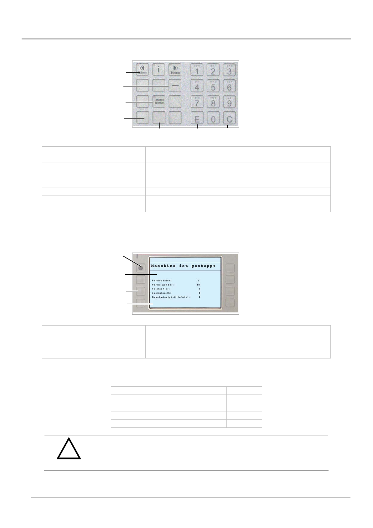
Group 4 description
6
(1)
(2)
(3)
(4)
(5)
(1) Scroll A flashing "scroll” key signals that further menu items are
available. These can be accessed by pressing the key.
(2) Minus Enters minus values
(3) Calculator
(4) Elevation table down Only works when the machine has stopped
(5) Manual welding Only works when the machine has stopped
(6) Enter Saves newly entered values
(7) Delete Deletes values called up
Group 3 description
Information which is normally standard and cannot be altered, appears on the display.
(6)
(7)
(1)
(2)
(3)
(4)
(1) Homepage Back to the homepage
(2) Status line
(3) Menu items Selection and display of menu items
(4) Standard info
Standard information:
Batch counter 0
Batch selected 50
Total counter 0
Examples / h 0
Speed (m/min) 0
Machine damage by pulling the power supply plug.
!
CAUTION
Electronic components can be damaged.
Only pull the power plug when the main switch is switched off..
Abb.1937-03
Subject to change without notice
23

6
Handling and Operation
6.2 Plan of the delta automatic delivery
The delta must be aligned to the folding machine so that the product stream is transferred
evenly and assigned to the relevant shafts. The height of the delivery must then be aligned
exactly to the height of the folding machine. The product stream must be conveyed to the
relevant shafts. The round belts must be parallel so that the products are not twisted..
Top view plan
6.3
5 2
1
Folding machine 4 Pre press roller
2
Round belt shaft 1 5 Main press roller
3
Round belt shaft 2 6 Shaft infeed
36 4
1
24
ubject to change without notice

Handling and Operation
6.4 Installing the automatic delivery
1. Place the machine in the middle in front of the folding machine.
2. Lock the adjusting feet (1). Spanner 12 (picture 1726)
Adjusting feet
6
1
Abb.1726
1. Establish power supply
2. Establish connection to the folding machine
3. Connect compressed air
!
CAUTION
Risk of stumbling over connecting cables and hoses.
Lay cables and hoses so that there are no places forming a tripping hazard
Subject to change without notice
25

6
Handling and Operation
Clamping lever
2
Abb.1040834
4. Open lever (2) on the delivery
5. Adjust delivery
6. Switch on main switch
Plan of the side view of the delivery
Brochure strikes the round belt opening exactly
26
ubject to change without notice

Setting up the machine
7 Setting up the machine
Setting the machine up for new jobs is described here. Each step is described in the order
that has proved itself in practise.
7.1 Infeed through the round belts
The round belts take the products from the folding machine or saddle stitcher.
For multiple up work, the products must be spread out. The angled infeed aligns the product
to the pile containers.
Note the sequence for adjustments:
1. upper round belt shaft 1
2. lower round belt shaft 2
3. upper round belt shaft 3
4. lower round belt shaft 4
7
Plan of the side view of the delivery
TOOLS REQUI4RED:
Allen key or screwdriver
Danger of being caught in running belts.
!
WARNING
Tools or fingers can be pulled in.
Let the belts run very slowly. Set the press drive at minimum speed for
this..
3
4
1
2
Subject to change without notice
27

7
Setting up the machine
Adjust upper round belts of shaft 1:
1. Loosen two infeed photocells BEX 02.01 and BEX02.02.
Ö Three belts are provided for each up-work as standard.
2. Open safety hood.
3. Set to inching mode and turn speed regulator.
4. Move the middle belt to the middle of the product.
Move both outer belts up to 20-30mm to the edge of the product.
View
Adjustment of the round belts
Upper round belt view
Abb.8879
1. Carry out this adjustment for each up-work of the product.
View
28
delta 3-up delta 5-up
Re-adjust the round belts for each up-work
ubject to change without notice

Setting up the machine
Adjust lower round belts of shaft 2:
1. Set the lower belts exactly below the upper belts.
Obere Rundriemen der Welle 3 einstellen:
Ö The products are driven along the course of the round belts. Set the round
1. Align belt (2) to the transport belt (1).
Ö see picture 1040837
2. Align both outside belts parallel to each other. In doing so, pay attention to the
number of grooves on round belt shaft 1.
3. Use the number of grooves to adjust both outer belts. This will ensure that the
product is not fed in at an angle.
Round belt adjustment
1
7
belts of shaft 3 so that there is an exact allocation to the relevant shaft.
2
Abb. 1040837
1 Transport belt 3 Photocell
2 Round belt
Wrong
Adjust lower round belts of shaft 4:
1. Place the lower belts exactly under the upper belts.
2. Repeat these steps for all up-works of the product.
3
Subject to change without notice
29

7
Setting up the machine
Position photocells
1. Fix the photocells between the round belts.
Ö On both outside streams
2. All belts must run freely.
3. Ensure that the round belts do not touch the photocells or their cables.
4. Ensure that there are no round belts under the photocell.
Ö The diode on the photocell does not light up
Adjustment for large formats
&
Round belts, large product, top view
For large formats, the products cannot be fed into the middle of the shaft.
The band is then no longer in the middle of the product. This has no
adverse effect on functionality.
7.2 Presse drive
The round belts and the folding machine must run at the same speed. This guarantees
trouble-free transfer of the products.
30
1. Adjust the speed using the press drive inching switch.
With the machine started
2. The difference in speed between the production machine and the delivery may
not be more than 10%.
3. Speed is shown in the display.
ubject to change without notice

Setting up the machine
7.3 Presssing unit
The pressing unit consists of pre and main pressing rollers. The pre-press rollers press any
trapped air out of the product. The main press rollers press the product with up to 3.5t.
7
Adjust pressing unit:
Adjust pressing unit
(4)
(3)
Abb.1735
1. Loosen all four star handles (1).
2. Open lever (2).
3. Put under 75% of the product (4).
4. Put under 50% of the product (3).
5. Carry out the adjustment on both sides
6. Close the lever
7. Re-tighten the star handles.
IP: Tighten only by hand
T
N
OTE: Check product for marking
(1)
(2)
Subject to change without notice
31

7
Setting up the machine
7.4 Sheet calibration
This function saves the linear measurement of the product being processed. All further
sheets are compared to this reference value. Photocells BEX2.1 und BEX2.2 measure the
sheet format.
1. Position infeed photocells BEX2.1 and BEX2.2 on the delivery above the
product.
2. Press the following sequence of keys.
1 Home position
2 Start
3 Calibrate, key flashes
4 Single sheet call-up
Control panel
Abb.491
Control panel
Abb.7677-2
(2)
(3)
(1)
(5)
(4)
32
7.5 Auto set up
The shingling axle adjusts automatically to the length of the product.
1. Press the following sequence of keys:
1 Calibrate sheet
2 Auto calibrate
ubject to change without notice

Setting up the machine
7.6 Shingling device
After the pressing unit, the products are taken over by the transport belts. The shingled
stream is formed at the shingling axle.
Shingle formation is automatically calculated and adjusted when the sheet is calibrated
The lower belts after the pressing unit can be adjusted in height. The shingling axle (2) is
adjusted to the product’s size using the “auto calibrate” function. The shingling axle can be
readjusted in the “manual function” menu. This takes place using the manual function key on
the operating controls. The upper / lower belt pressing force must be lowered for thick
products. This takes place by turning the shingling axle by up to +/-90°. The shingling axle
is supported eccentrically.
Adjust infeed angle:
7
Shingling axle
Abb.1616
1. Loosen knurled screw (1)
2. Adjust lower belts (2)
3. Tighten knurled screw
1
2
Subject to change without notice
33

7
Setting up the machine
Reduce upper/lower belt pressing force:
Shingling axle
2
1
Abb.8921
1. Loosen set screw (1)
2. Adjust the shingling axle (2) to the thickness of the product
3. Tighten set screw
7.7 Shaft infeed
Adjust upper belt:
In addition, the product can be fed by adjusting the upper belts.
1. Turn the knurled screw (4)
Ö The upper belt pressure shaft (3) is adjusted
Upper belt pressure shaft
4
34
3
Abb.1653
ubject to change without notice

Setting up the machine
Adjust support finger:
The product is additionally stabilised by raising the support finger so that it does not bend
into the shaft.
TIP: Important adjustment for smooth operation.
1. Lift the stop rocker (7) and let it engage
2. Loosen knurled screw (6)
3. Adjust the support finger (5) to the format
4. Loosen the stop rocker holder and locking button (8)
5. Engage the stop rocker back down
Support finger
7
7
8
5
6
Abb.1658
Subject to change without notice
35

7
Setting up the machine
Adjust pressure axle/ contact rollers:
1. Adjust the pressure axle (9) using the knurled screw (10)
Ö Adjust equally on both sides
Ö Loosen the set screw on the contact rollers (11)
Ö Adjust the contact rollers to the product
Ö Tighten set screw
Pressure axle / contact rollers
10
9
11
Abb.1654
Knurled screw contour pre-setting
36
3.2.a
ubject to change without notice

Setting up the machine
7.8 Shaftt
The products are stacked in the shaft and knocked-up by jogging plates. This ensures that a
tidy pile is formed. Two lateral jogging plates and the back jogger on the adjusting frame
undertake this function.
Adjust lateral jogging plates:
Two jogging plates are required per up-work.
Jogging plates
7
(1)
(1)
Abb.1654
1. Loosen lever (1)
2. Adjust both jogging plates to the height of the product
Ö The jogging plates are located in the narrowest position when the machine
stops
Set the adjusting frame to the product length:
(1)
Abb.1731
1. Loosen lever (1)
Subject to change without notice
(2)
37

7
Setting up the machine
2. Set the adjusting frame to the product width,
by turning the knurled screw (2)
Adjusting the angle of the rear jogging plate
(4)
(2)
(1)
Abb.1040864
1. Loosen both screws (1) using allen key no. 4.
2. Set the angle of the jogging plate to the products.
Ö by adjusting the lever (2).
3. Tighten both screws again (1).
38
ubject to change without notice

Setting up the machine
7.9 Delivery unit
By adjusting the side loader to the required delivery side, the machine automatically identifies
the delivery direction. Adjustable in 4 delivery directions.
Adjusting the side loader to the package lift
7
Abb.1040836
Package lift
Abb.1598
!
WARNING
(1)
Danger of being crushed by pusher moving upwards.
Tools or fingers can be pulled in.
Do not reach into open area (1).
Subject to change without notice
39

7
Setting up the machine
7.10 Adjustments at the operator controls
(3)
1 Home position 4 Single sheet call-up
2 Auto set up 5 Inching button
3 Set up 6 Calibrate
Changing values:
1. Select menu
2. Select function
3. Enter value
4. Confirm with “E”
5. if required, delete with “C”
(2)
(1)
(6)
(5)
Picture 497
(4)
40
Subject to change without notice

Setting up the machine
7.10.1 Batch counter
The batch amount is the number of products per package
1. Press the set-up key on the operator controls
Ö Enter the number of pieces in the batch and press “E”.
7.10.2 Stacking level compensation
Enter the amount at which the stacking level compensator should activate.
0 = switched off.
7.10.3 Sheet thickness
The destacking amount is calculated by entering the sheet thickness. The destacking
process repeats itself once the destacking amount is reached.
1. Measure the height of 10 sheets at the spine.
2. Press the set-up button on the operator controls and follow the instructions.
Reduce the value if the machine destacks too quickly
Increase the value if the machine destacks too slowly
7
Measuring device
Picture 1921
7.10.4 Total counter
Set by entering a user-defined value, or set to zero
7.10.5 Package lift cycles
Number of packaging cycles until the package lift starts.
7.10.6 Load default values
The factory settings for this menu are loaded by entering 1
7.10.7 Band type
The type of band can be selected here. Paper or PE.
Subject to change without notice
41

7
Setting up the machine
7.10.8 Jogging function in the packaging cycle
The jogging function during the packaging cycle can be blocked here
0 = normal
1 = continuous operation in the packaging cycle
7.11 Single sheet operation
Single sheet mode is recommended for sensitive or freshly-printed products, thick products
or a low folding speed.
Choose single sheet operation for products with a sensitive surface e.g. pages of books or
art printing. It is possible that these products could be marked during shingling or when the
stopper reaches into the shingled stream. Single sheet operation should also be chosen for
freshly-printed products. These products tend to rub against each other as the products are
pushed on top of each other during shingle formation.
The [shingled stream / single sheet] key alternates between these two operating modes.
Single sheet mode can be recognised by the transport belts running permanently.
7.12 Shingled stream operation
Shingled stream operation is suitable for non sensitive products, small formats or high
production speed, e.g. newspaper inserts, mailings, flyers.
The transport belt is timed with photocells BEX2.1 and BEX2.2 and only runs when products
are fed in. Shingle formation can be increased or decreased as required. This is carried out
in the optimisation menu.
42
Subject to change without notice

Optimisation menu
8 Optimisation menu
Adjustments which deviate from the default values can be made in the optimisation menu.
8.1 Package compression
Adjustment to package compression during production.
The values lie between -200 mm and +200 mm. The higher the value
the stronger the pressure on the package.
8.2 Intermediate position
The intermediate position starts after the last product in the stack has fallen on to the
elevation table. The intermediate position is required so that the pressing rails can be
retracted.
For products which spring open, it can be necessary to lower the intermediate position so
that there is enough room for the pressing rails to retract.
The setting range lies between -200 mm and +200 mm. Ideally, after reaching the
intermediate position, the upper edge of the package is approx. 20 mm under the pressing
rails.
8
8.3 Pressing rails earlier / later
After reaching the intermediate position, the pressing rails move to their working position.
The package can be pressed. Depending on the format, it could make sense to move the
pressing rails to the working position earlier or later. The smaller the value, the earlier the
pressing rails are started.
Pressing rails started too soon
Picture 932
Pressing rails started too late
Picture 933
8.4 Sheet gap (only in single sheet mode)
The sheet gap in single sheet mode can be adjusted here. Adjustment made in mm.
Subject to change without notice
43

8
Optimisation menu
8.5 Sheet fall time (only in single sheet mode)
The sheet fall time can be entered here. Enter in msec.
8.6 Shingling
Overlapping in the shingled stream can be adjusted in the shingling menu item. The values
can be varied from 40% - 90%. At 40%, the products will overlap 40%.
8.7 Stop
The stop time can be adjusted proportionally until the interruption in the shingled steam is
sufficient for the pressing rails to extend. Values can be set at 10% to 150%. Default value
75%.
8.8 Amount of folding errors
The number of recognised folding errors at which the machine will stop can be entered here.
0 = switched off.
8.9 Load default values
Default values are loaded by entering 1.
8.10 Tolerance
All products are measured by the delivery’s infeed photocell. Now, extra tolerance to the
reference value, which is measured by the calibrate key, can be entered in 0.1 mm. Products
which exceed this value + the tolerance value are ejected via the waste sheet deflector.
8.11 Jogging time
The jogging frequency can be adjusted here. The set time in msec. units corresponds to one
full phase.
8.12 Jogging motor
Jogging can be adjusted if required. The lower the value, the slower the jogging frequency.
All joggers, back joggers and side joggers are simultaneously set with this adjustment.
44
8.13 Pre-collection finger delay (not active on the delta705)
In the working position, extension of the pre-collection finger can be delayed with this
adjustment. Adjustment depends on the product and the speed. The greater this value, the
later the pre-collection finger retracts
Subject to change without notice

Optimisation menu
8.14 Stacking level compensation delay OUT (not active on the
As the elevation table returns from the intermediate position to the pressing unit, the flaps on
the stacking level compensator are reset. Resetting the stacking level compensator is
delayed by increasing this value.
This can be necessary for spines that spread out excessively at the spine.
8.15 Welding time
This adjustment determines for how long the band is welded. Band type is selected in the
option menu. Paper or plastic film. The welding time is chosen depending on the material.
8.16 Cooling time
This adjustment determines for how long the band is cooled. Band type is selected in the
option menu. Paper or plastic film. The cooling time is chosen depending on the material.
8.17 Sheet recognition
8
delta705)
In double stream, it could happen that products arrive offset in the delivery. Ejection of the
products can be cancelled by changing sheet recognition via a photocell.
8.18 Shingling belt speed (only in single sheet mode)
Constant speed for the shingling belt in m/sec. .
0 = automatic mode
Subject to change without notice
45

9
Quick set-up
9 Quick set-up
Short introduction for quickly setting-up the machine:
More detailed information can be found on the pages indicated.
9.1 Mechanical set-up
1. Set up machine to the previous machine and lock the adjusting feet Page 25
2. Adjust delivery’s height Page 25
3. Call up one product from the folding machine or saddle stitcher
and adjust round belts Page 20
4. Set infeed photocell Page 19
5. Adjust pressing unit Page 31
- Folding machine 1. Pre press roller 75%
2. Main press roller 50%
- Saddle stitcher 1. Pre press roller 125%
2. Main press roller approx. 100% or more
Controls:
1. Press calibrate key Page 37
2. Call up product
3. Press auto calibrate key Page32
6. Call up the product and allow it to run up to the shaft by
pressing the rocker switch. Page 37
7. Adjust lateral jogging plates to the product. Page 37
8. Adjust adjusting frame to the product width Page 34
9. Adjust support finger under the product edges. Page 34
46
9.2 Controls
1. Enter amount Page 39
2. Set total counter to zero Page 41
3. Select single sheet or shingled stream depending on
the product and speed. Page 42
4. Align the round belt’s speed on the folding machine
or saddle stitcher +/-. 10%. Page 30
Subject to change without notice

Quick Check
10 Quick Check
9 questions that you should ask yourself after set up.
10
1. Is the height of the delivery to the folding machine correct?
Plan
2. Are the brochures conveyed at an equally slanted angle?
3. Are the round belts running parallel to each other and are they adjusted
correctly to the product?
View
Subject to change without notice
47

10
Quick Check
4. Is the difference in speed between the folding machine and the automatic
bundling delivery less than 10%?
5. Are the infeed photocells free?
6. Have the pre and main pressing rollers been adjusted to the product
thickness?
View
7. Do the transport belts convey the shingled stream continuously without
faltering?
8. Are the shingled streams fed into the middle of the shafts?
View
9. Have the support fingers in front of the shaft been adjusted?
Upper round belts view
48
3.2.a
Subject to change without notice

Sensors, Pneumatics, Motors
11 Sensors, Pneumatics, Motors
11.1 The sensors used and their function
Article
No.
Description Functional principle Picture
11
61.00002 Reflection light
scanner TW1040mm
Reflection light
scanner with
background
shielding
B8, B9….
61.00025
61.00026
63.00117 Inductive proximity
Rotary pulse
encoder
switch
A transmitter sends out light in the
infrared range, which reflects from the
detected object and is sent back to the
receiver in the light scanner.
Objects, which are more than 40 mm
away are suppressed by this.
When an object is detected, the LED
on the scanner lights up and the output
returns 24V DC.
.
Rotary pulse encoders convert
rotational turns into impulses. These
signals can be evaluated so that
conclusions can be drawn about the
paths covered.
The encoders fitted by palamides are
equipped with two impulse tracks,
which also enable recognition of the
direction of rotation (left/right turning).
The second track (B-track) is placed at
90° to the A-track.
Encoders with 32 and 200 impulses
respectively are used on the delta. As
the sensors do not have any sort of
display, their function can be checked
under service / TPU counter.
If a metal part penetrates the working
area of the sensor, losses occur in the
eddy current of the magnetic field
shown by the sensor. These are
recognised by the sensor and it sends
a signal with 24V DC to its output.
At the same time its status is signalled
to the terminal by a LED. Generally,
the nearer the detected metal object is,
the quicker the sensor switches.
links rechts
Subject to change without notice
49

11
BE 5.09
BE 5.10
BE 4.01
BE 5.05
BE 5.07
BE 5.06
BE 5.08
BE 4.04
BE 4.02
Sensors, Pneumatics, Motors
11.2 Sensors
Delta sensors overview
BE 2.01
BE 2.02
BE 2.03
BE 2.02
BE 2.01
Abb.575-5
Delta sensors overview
BE 4.07
BE 4.08
BE 5.04
50
Abb.1589-r
Subject to change without notice

Sensors, Pneumatics, Motors
Sensors BEX 2.1 and BEX 2.2
Delivery
11
BEX2.1
BEX2.2
Abb.567
Sensor Position/ Description Function
BEX2.1 Sensor sheet measurement Count and measure sheets
BEX2.2 Sensor sheet measurement Count and measure sheets
Shaft encoder BEX 2.03
Press shaft encoder
BEX 2.03
Abb. 550
Sensor Position/ Description Function
BEX 2.03 Press shaft encoder The current rotational speed is sent to the controls
Subject to change without notice
51

11
BE4.01
Sensors, Pneumatics, Motors
Shaft encoder BE 4.01
Belt drive shaft encoder
Abb.552
Sensor Position/ Description Function
BE4.01 Belt drive shaft encoder Rotational speed control of the belt drive
Shaft encoder BE 4.02
Elevation table shaft encoder
BE4.04
BE4.02
52
Abb.565
Sensor Position/ Description Function
BE4.02 Elevation table shaft encoder Determines the position of the elevation table
BE4.04 Sensor Elevation table home position
Subject to change without notice

Sensors, Pneumatics, Motors
Sensor BE 4.05
Right side loader
BE4.05
Abb.07
Sensor Position/ Description Function
11
BE4.06
BE 4.05 Right side loader
BE 4.06 Left side loader
Sensor BE 4.07 und BE 4.08
Ejector shaft encoder
BE 4.07
Abb. 1030565
BE 4.08
Sensor Position/ Description Function
BE 4.07 Ejector in home position
BE 4.08 Ejector in operating
position
Subject to change without notice
53

11
Sensors, Pneumatics, Motors
Sensor 5.04
Package lift right side
Abb. 569
Sensor Position/ Description Function
BE 5.04 Package lift right side When activated, the package lift is located on the
right hand side
Sensor BE 5.05
Pressing rails
BE 5.05
54
Abb.570
Sensor Position/ Description Function
BE 5.05 Pressing rails in home position
Subject to change without notice

Sensors, Pneumatics, Motors
Sensor BE 5.08 and Sensor BE 5.06
Pressing rails
11
BE 5.08
BE 5.06
Abb.571
Sensor Position/ Description Function
BE 5.08 Welding die in operating position
BE 5.06 Pressing rails in operating position
Sensor BE 5.07
Welding die in home position
BE 5.07
Abb.578
Sensor Position/ Description Function
BE 5.07 Welding die in home position
Subject to change without notice
55

11
Sensors, Pneumatics, Motors
Sensors BE 5.09 and BE 5.10
Jogging plate sensors
BE 5.09
BE 5.10
Abb.580
Sensor Position/ Description Function
BE 5.09. Jogging plate narrowest position
BE 5.10 Jogging plate widest position
Sensors BE11, BE11.02 and BE11.04
Package lift
BE 11.04
BE 11.02
BE 11.01
56
Abb.1030537
Sensor Position/ Description Function
BE11.01 Package lift down
BE11.02 Package lift up
BE11.04 Slider operating position
Subject to change without notice

Sensors, Pneumatics, Motors
11.3 Cylinder
delta cylinder overview
Z7.1
11
Z9
Z11.1
Z10.1
Abb.575-5
delta cylinder overview
Z13
Z12.1
Z4
Z8
Z2.1/Z2.6 + Z5.1/Z5.2
Inside the machine
Z7.2
Abb.1589-r
Subject to change without notice
Z11.2
Z10.2
57

11
Sensors, Pneumatics, Motors
Waste sheet deflector cylinder
Open waste sheet deflector / pressing unit
Z13
Z12.1
Abb.550
Cylinder Position/ Description Function
Z12.1 Open pressing unit left
Z13 Waste sheet deflector
Stopper cylinder
Stopper cylinder
Z9
58
Abb.553
Cylinder Position/ Description Function
Z9 Stopper
Subject to change without notice

Sensors, Pneumatics, Motors
Cylinder shaft narrower/wider / small format
Shaft
11
Z2.1 – Z2.6
Cylinder Position/ Description Function
Z2.1-Z2.6 Small format option (pre-
Z5.1/Z5.2 Shaft narrower/wider
Ejector cylinder
Z5.1 / Z5.2
Abb.558
collection fingers)
Ejector
Abb.556
Cylinder Position/ Description Function
Z4 Ejector
Subject to change without notice
Z4
59

11
Sensors, Pneumatics, Motors
essing rails / welding die cylinder
Pressing rails / welding die t
Z2.1 – Z2.6
Cylinder Position/ Description Function
Z10.1 Welding die left
Z11.1 Pressing rails left
Band tensioner cylinder
Z5.1 / Z5.2
Abb.558
60
Abb.8560
Cylinder Position/ Description Function
Z8 Upper band tensioner
Subject to change without notice

Sensors, Pneumatics, Motors
Pressing rails / welding die cylinder
Package lift
Abb.1030574
Cylinder Position/ Description Funktion
11
Z15
Z14
YA11.05
YA11.04
Z15 Slider cylinder
Z14. Package table cylinder
YA11.04 Valve V10 Package lift upwards
YA11.05 Valve V11 Extend slider
Side loader cylinder
Right side loader
Z1
Abb.07
Cylinder Position/ Description Function
Z1 Side loader cylinder
Subject to change without notice
61

11
M5
Sensors, Pneumatics, Motors
11.4 Motors
Delta motors overview
Abb.575-5
Delta motors overview
M11
M2
M3
Behind control
cabinet
Abb.1589-r
M6.2
M4
62
M2 Press M5 Side jogger
M3 Belt drive M6 Shaft rear wall jogger
M4 Elevation table M11 Format adjustment
Subject to change without notice
 Loading...