

Painless Performance 10309 Instructions Manual

Wire Harness Installation
Instructions
Manual #90571 PART 1
For Installing:
#10309 Basic Customizable Nostalgia All Black
Chassis Harness – 17 Circuit
Painless Performance Products recommends you, the installer, read this
installation manual from front to back before installing this harness. Due
to the variables in modifications that can be done to vehicles, reading
this manual will give you considerable insight on the proper installation
of this harness.

Perfect Performance Products, LLC
Painless Performance Products Division
2501 Ludelle Street
Fort Worth, TX 76105-1036
800-423-9696 phone – 817-244-4024 fax
Web Site: www.painlessperformance.com
E-Mail: painless@painlessperformance.com
If you have any questions concerning the installation of this harness, feel
free to call Painless Performance Products' tech line at 1-800-423-9696.
Calls are answered from 8am to 5pm central time, Monday thru Thursday,
8am to4:30pm Fridays, except holidays.
We have attempted to provide you with as accurate instructions as
possible, and are always concerned about corrections or improvements
that can be made. If you have found any errors or omissions, or if you
simply have comments or suggestions concerning these instructions,
please write us at the address above, send us a fax at (817) 244-4024 or email us at painless@painlessperformance.com. We sincerely appreciate
your business.
Perfect Performance Products, LLC shall in no event be liable in contract
or tort (including negligence) for special, indirect, incidental, or
consequential damages, such as but not limited to, loss of property
damage, or any other damages, costs or expenses which might be claimed
as the result of the use or failure of the goods sold hereby, except only the
cost of repair or replacement.
90571 Installation Manual
January 14, 2014
Copyright 2013 by Perfect Performance Products, LLC
2

CAUTION: BEFORE THE REMOVAL OF YOUR ORIGINAL HARNESS
AND/OR THE INSTALL OF YOUR NEW PAINLESS HARNESS, DISCONNECT
THE POWER FROM YOUR VEHICLE BY REMOVING THE NEGATIVE OR
POSITIVE BATTERY CABLE FROM THE BATTERY.THE BATTERY IS NOT
TO BE CONNECTED UNTIL THE PAINLESS HARNESS HAS BEEN
INSTALLED AND TESTED.
A full color copy of these instructions can be found online at
http://www.painlessperformance.com/InfoSearch/manuals.php
If your vehicle has an existing harness, you will want to retain it for the
possible re-use of various pigtails & connector housings particular to
your application. During the removal process, avoid making any
unnecessary cuts.
This harness is universal in nature, meaning, all ends are left open to
allow you to cut wire to length and install the appropriate connection.
The package of terminals included with the harness will enable you to
make connections.
Only printed wires will have a 900-series number. These 900-series
numbers are used to identify various wires and circuits in the wiring
diagrams that are a part of these instructions.
In the event that there are unused or unconnected wires, the ends of all
wires labeled in this instruction manual as “POWER” or wires printed
with “B+” in the description, will need to have the ends terminated with
an insulated terminal or taped. Doing so will prevent the wires shorting
and causing harness failure or fire.
3

TABLE OF CONTENTS
PAGE # SECTION
6 INTRODUCTION
7 CONTENTS
8 SMALL PARTS
9 TOOLS NEEDED
10 PRE-INSTALLATION GUIDELINES
11 INSTALLING FACTORY TERMINALS
12 GROUNDS
15 FUSE BLOCK
Horn relay
Flashers
16 Fuse Identification
17 Relays & Switches
18 Fuse Block Mounting
20 FUSE BLOCK HARNESS ROUTING
22 COMPONENT OUTPUT HARNESS ROUTING
24 HEADLIGHT SECTION CONNECTIONS
Left/Driver Side Headlight
26 Headlight w/ Pigtails
28 Left Turn/Park Light
29 Horn
Right Turn/Park Light, Right Headlight
31 ENGINE / IGNITION SECTION
Coil/ignition
32 Ballast Bypass
33 Tachometer
35 Engine Sending Units/Switches
Coolant Temperature
37 Oil Pressure, Choke
39 START/CHARGE SECTION
Alternator
40 Charge Indicator Light
42 GM SI Series Alternators
43 GM CS-130 Alternators
45 GM CS-130D Alternators
47 GM Externally Regulated Alternator
48 Ford Externally Regulated Alternator
49 Ford Internally Regulated Alternator (3G)
50 MOPAR Externally Regulated Alternator
52 MIDI Fuse
54 Starter
4

Schematics, Diagrams, & Photos
PAGE # SECTION
6 NOTES diagram
7 CONTENTS photo
9 JAW STYLE CRIMPERS picture
11 TERMINAL INSTALLATION pictures
13 GOOD & BAD GROUND SOURCE diagrams
14 GROUND SCHEMATIC
16 FUSE IDENTIFICATION diagrams
18 FUSE BLOCK MOUNTING photos
19 FUSE BLOCK HARNESS diagram
20 FUSE BLOCK HARNESS ROUTING diagram
21 COMPONENT OUTPUT HARNESS diagram
22 COMPONENT OUTPUT HARNESS ROUTING diagram
23 COMPONENT & FUSE BLOCK HARNESSES TOGETHER diagram
25 HEADLIGHT CONNECTOR PIN OUT photo
30 HEADLIGHT SECTION SCHEMATIC
34 COIL CONNECTIONS diagram
BALLAST RESISTOR CONNECTIONS diagram
MSD CONNECTIONS diagram
35 HEI COIL ON CAP CONNECTIONS photo
38 ENGINE SECTION SCHEMATIC
39 CHARGE INDICATOR LIGHT diagram
43 GM SI SERIES ALTERNATOR diagram
44 GM CS-130 ALTERNATOR diagram
46 GM CS-130D ALTERNATOR diagram
47 GM EXTERNALLY REGULATED ALTERNATOR diagram
49 Ford EXTERNALLY REGULATED ALTERNATOR diagram
50 Ford INTERNALLY REGULATED ALTERNATOR (3G) diagram
51 MOPAR EXTERNALLY REGULATED ALTERNATOR diagram
52 MIDI FUSE MOUNTING photo
53 BATTERY POWER/MIDI FUSE SCHEMATIC
55 GM STARTER diagram
56 FORD STARTER SOLENOID diagram
57 MOPAR STARTER RELAY diagram
58 MOPAR “SR14” RELAY diagram
5
INTRODUCTION
Thank you for your purchase of a Painless Performance product. These
instructions along with the Painless harness have been designed to allow you, the
installer, the cleanest and easiest install possible.
During the course of reading this manual you will notice wire colors with a slash,
as an example Black/White. This indicates a wire with a stripe. The first color is the
main color of the wire and the color after the slash is the stripe color. In the case of the
example, Black/White indicates a black wire with a white stripe.
Do not let the length of this instruction manual intimidate you. Much of the
information contained in this manual is helpful information about each wire, where the
wire comes from, where it goes, why a component needs it, etc. In many cases, there
are multiple schematics as well as alternate connection options for the same
wire/connection point due this being a universal harness. You will find that the actual
install portions of this manual are pretty straight forward and easy to follow.
The install portions are noted with a round bullet note, as seen here.
Individual components and sections are labeled with printed tags for easy
identification. As this harness is all black, conventional GM color code was followed
based on the stripe found on the wire. These colors, along with the schematic diagrams
found throughout this manual and the printed circuit numbers and description printed on
the wire, will help you identify the different circuits during installation and later on if
additions to the overall system are necessary.
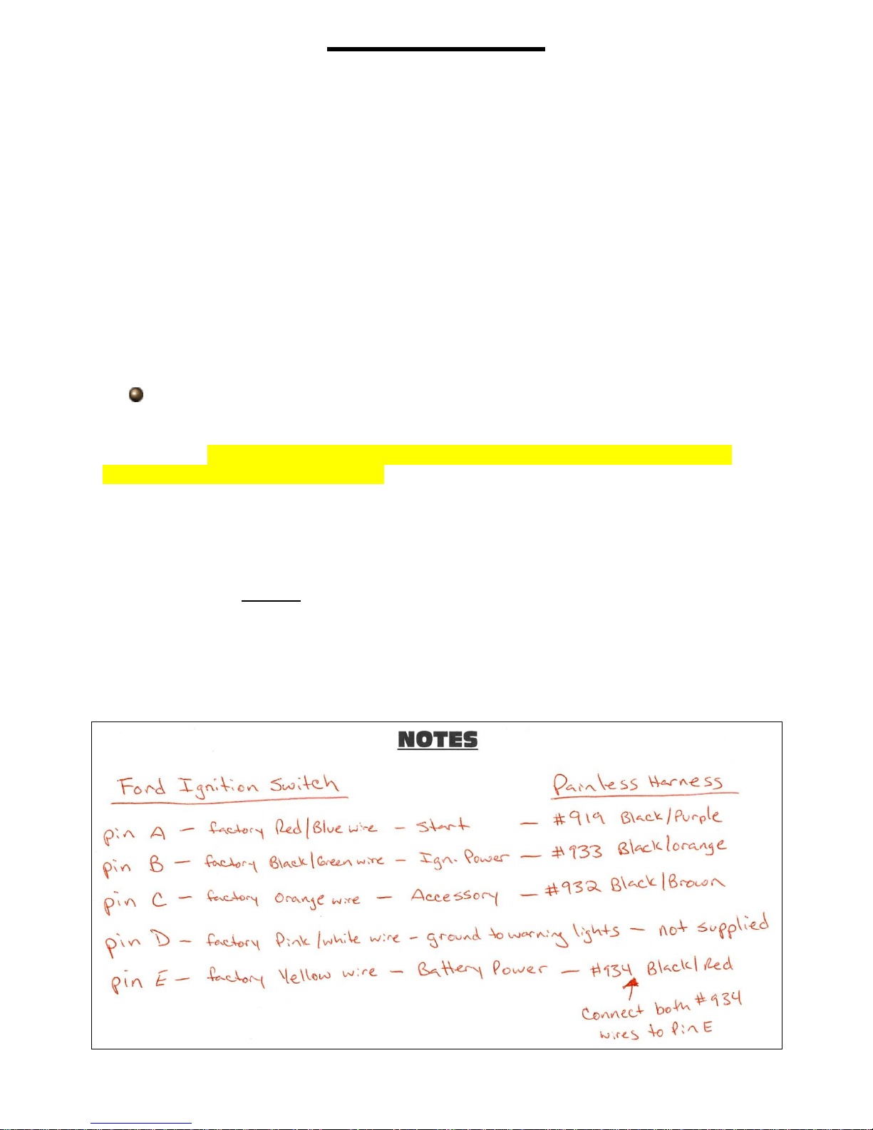
As you read through the installation manual prior to actual installation, use the
blank areas titled NOTES in each section and in the back of the manual to list
components you are connecting to on your vehicle, factory or manufacturer wires that
are coming from the component, then list their function/ power requirement. You can
then use the text in the manual and the wire index in the back of the manual to identify
the wire and circuit number in the Painless harness that will connect to that requirement.
For example, a dash mounted 60’s-70’s Ford ignition switch:
6

Planning connections beforehand will give you a better understanding of what
needs to be routed, if any additional wires may need to be added, and how to make the
best use of any extra circuits provided in the Painless harness.
CONTENTS OF THE PAINLESS WIRE HARNESS KIT
Refer to the Contents Figure (below) to take inventory. See that you have
everything you’re intended to have in this kit. If you find that anything is missing or
damaged, please contact the dealer where you obtained the kit or Painless
Performance at (800) 423-9696.
The Painless Wire Harness Kit should contain the following:
Power Supply Harness Harness, with the fuse block pre-installed
Output supply harness
3 rolled wires: Red, Black/Yellow, and Black/Red
Parts Kits: (1) insulated loose piece terminals kit (1) un-insulated terminal kit
3 bag kits: Alternator bag, heat shrink bag, a bag w/ zip ties and other parts
This manual: parts #1 and #2
CONTENT FIGURE- All of the parts in the Painless kit
7

You may be wondering… “Why two harnesses in this kit instead of just one
grouped together like most harnesses?”
You will notice one harness has a fuse block pre-installed. This will be known in
this manual as the FUSE BLOCK HARNESS. This harness contains all of the power
wires to components like the headlight switch, turn signal switch, brake switch etc. and
also supplies power to the fuse block from the battery. This harness has extra length
built in to allow the fuse block to be mounted up to 10’ away from major components like
the headlight switch and the ignition switch.
The secondary harness, or COMPONENT OUTPUT HARNESS, contains wires
from individual switches and sending units to the components they operate. As an
example: all the wires from the turn signal switch to the turn indicators, oil/temp/fuel
sending units to the gauges, and headlight switch out to the exterior lights. Since the
majority of this harness involves connections made to components of the dash, we are
given a common reference point since most dashes are slightly forward of the center of
the vehicle. This allows this secondary harness to have shorter lengths than the fuse
block harness but still provide ample length for just about any install. These shorter
lengths result in less waste when you route and cut these wires to length.
SMALL PARTS
Included with the Painless harness are parts kits containing miscellaneous
terminals, fuses, screws, and nuts. Many of the terminals are non-insulated and will
require heat shrink to be applied after the terminal has been properly crimped. Heat
shrink has been supplied.
These non-insulated terminals follow the same “old-school” traditional feel of this
nostalgia harness; colored insulated terminals would seem out of place. When crimping
these terminals, take notice to the split in the terminal. Make sure the smooth side of the
jaw on the crimper goes towards this split.
One small bag kit, labeled ALTERNATOR, contains
all of the components for an inline fuse installation and
alternator connections. This fuse is to isolate the battery
from the alternator and Painless harness. These parts
include the base with cover, fuse, mounting screws and ring
terminals.
“Umbrella” style zip ties have been provided for you
to attach the Painless harness to the inner fender, core
support, and/or frame. These zip ties fit into ¼” holes left
behind by factory plastic retainer loops or those created with
a drill by the installer.
8
Remember, as the zip ties are installed and the harness is routed, wrap the tie
around the harness and LOOSELY tie the harness. Make sure you leave enough room
to pull and push the harness as you make your connections. Only when all connections
have been made will you tighten the zip ties.
TOOLS NEEDED
In addition to your regular hand tools, you will need, at least, the following tools:
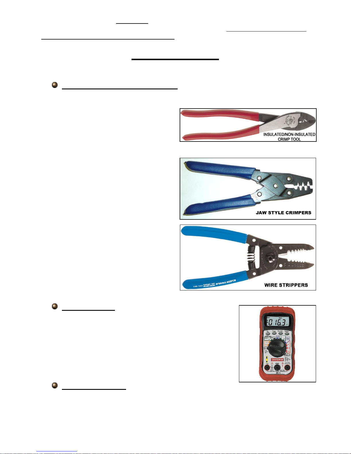
Wire Crimping and Stripping Tools:
This style of hand crimper can be purchased from just about any local auto parts store,
home improvement store or can also be
purchased online. You will need this style
of crimper to crimp the heat shrinkable and
non-heat shrinkable insulated terminals
included in the small parts kit.
Another style of crimpers are “Jaw
Crimpers” or “Roll Over Crimpers”. These
crimpers will crimp factory style, uninsulated terminals. These types of
terminals are provided in the kit for
connections to an HEI distributor,
headlights and factory style alternator. If
none can be found locally, these crimpers
can be found using Painless part # 70900.
A good set of wire strippers are required to
strip wire properly. This style of wire
stripper is ideal for this harness install
because of its ability to properly strip wire
gauges 10 to 20.These are available from
just about any local auto part store,
electrical supply shop, home improvement
store or can be purchased online.
Volt/Ohm Meter:
A Volt/Ohm meter is always a good tool to have on hand when
installing any type of electrical components into any vehicle.
Most basic units provide the two functions required to diagnose
electrical issues seen during a harness install. These two
functions are the ability to read DC Voltage and electrical
continuity or Ohms. They can be purchased from any home
improvement store, local hardware store and electrical supply
shop and online.
Electric Drill & Bits:
A drill and bits are needed in order to use the screws provided with the kit for the MIDI
fuse holder and the fuse block mounting.
9
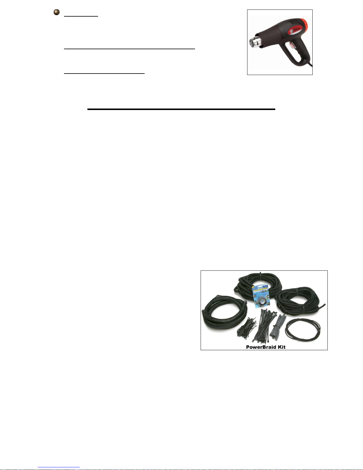
Heat Gun:
Very useful to shrink the heat-shrinkable terminals found in the
parts kit.
Small (10 amp or less) Battery Charger
See TESTING THE SYSTEM located on page 145.
Factory Wire Schematic
This isn’t absolutely necessary; however, having one handy is
good practice with any electrical job.
PRE-INSTALLATION GUIDELINES
The installation of your wire harness mainly consists of two parts:
• The physical routing and securing of the wire harness, wires, and groups.
• The proper connection of the individual circuits.
These two major tasks are not separate steps, but are combined. That is, you will
route some wires and make some connections, route more wires and make more
connections. Harness routing will depend greatly on mounting locations of things such
as gauges, shifters, lighting lenses/headlights, etc. Harness routing also depends a
great deal on fuse block mounting location and to the extent you want to secure and
conceal the harness. This aspect will be more prominent in the ENGINE SECTION
wiring, where much of the harness is usually visible.
The best pre-installation practice is to become familiar with the harness by
locating each of the harness sections. A good way to do this is by laying out the wire
harness on the floor and identifying each of the section labels found on the harness as
you read through the manual. The wire index in the back of the second manual will help
to quickly identify each wire in these sections.
During the install, wires should be
bundled into groups. Use nylon ties, split loom,
or tape. Exposed wires of the engine
compartment and wires running to the rear of
the vehicles may need some sort of wiring loom
or covering. Painless offers Power Braid Kit part
#70920 and ClassicBraid #70970 to fill this
need. These kits include everything you will
need to add extra protection to your new
harness.
10
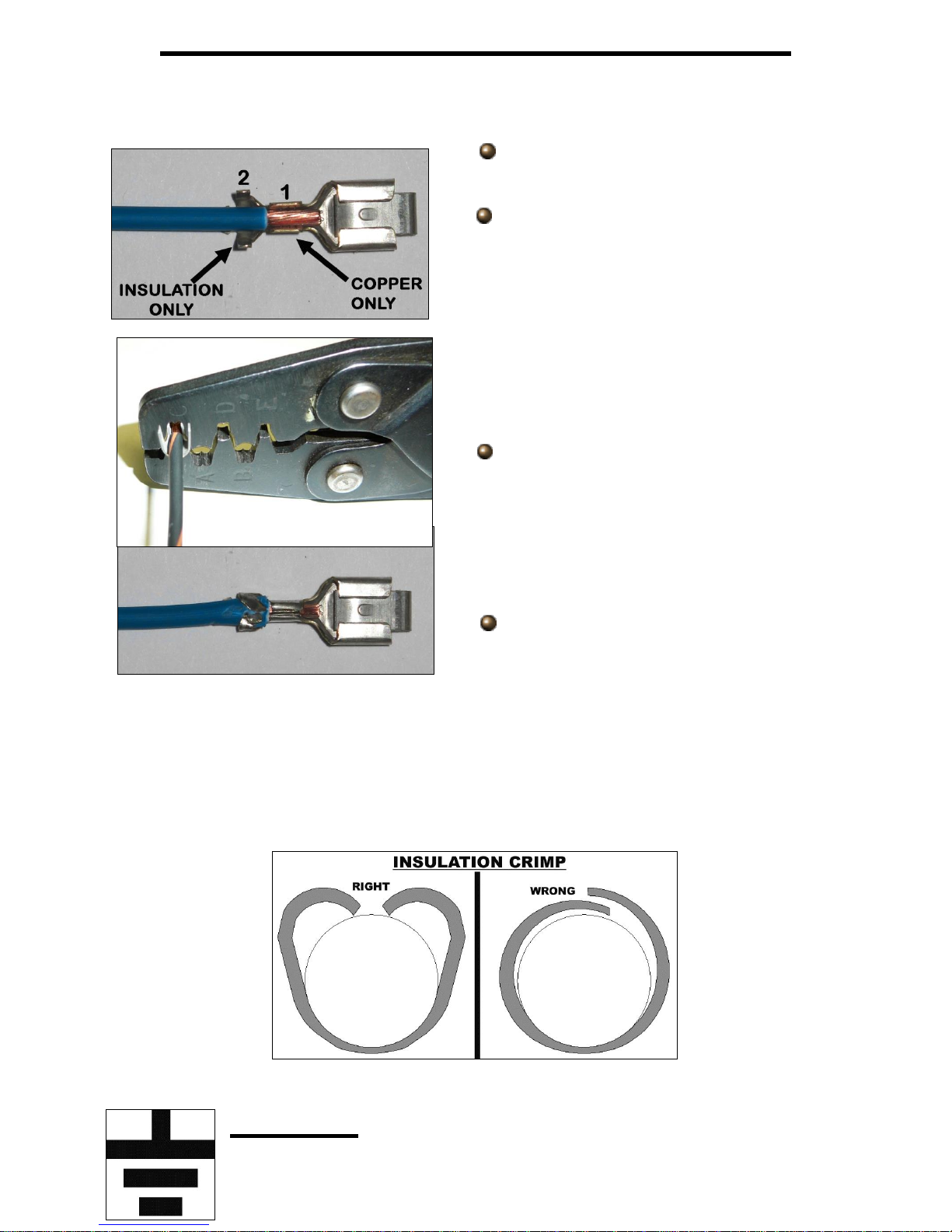
INSTALLING FACTORY STYLE TERMINALS
In the parts kit you will see different non-insulated male and female terminals.
These terminals are for factory style connections and require roll over crimpers.
Strip about ¼” of insulation off of the
wire.
Insert the wire into the terminal. There
are 2 terminal straps on the terminal. For
instructional purposes, we will label them 1 and
2. Strap 1 crimps the exposed copper stands of
the wire, while strap 2 crimps the wire
insulation. Make sure your strip length is long
enough to ensure only copper strands are
crimped by Strap 1, but make sure it is short
enough that only insulation is crimper by Strap
2. The photo to the left best demonstrates this.
Using the appropriate jaw on the
crimpers, crimp Strap 1. The appropriate jaw
depends on the wire gauge as well as the
terminal stiffness. If you are unsure which jaw
to use, you can always start with the biggest
and work your way down until you get a tight
crimp.
With Strap 1 crimped you can move
onto crimping the insulation strap, Strap 2.
Place Strap 2 into the appropriate jaw of the
crimpers. This jaw will be larger than the one
used to crimp the first strap. Crimp down on Strap 2 making sure the strap folds
downward into the wire, and not overlapping itself, refer to the drawing below.
Overlapping could cause problems with the terminal fitting into the factory
connector.
Grounds
11
Throughout this instruction manual and when looking at the Painless harness you
will see the word GROUND, maybe you’ve seen the ground symbol on wire diagrams?
What exactly is a ground and why do you need it?
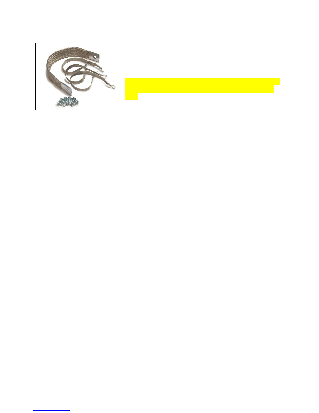
You’ve probably noticed the large cable coming
from the negative side of your battery going down to the
sub frame or to the engine. This cable allows voltage to
get back to the battery through the metal of the sub
frame and all the other metal pieces bolted to the frame.
It is also important to have ground cables going from the
sub frame to the engine and from the sub frame to the
body. Painless offers part # 40140, seen in the photo, to
supply proper grounds back to the battery.
A ground is simply the common path voltage takes back to the battery. A ground,
or chassis ground as it is often called, is any bare metal surface found on the vehicle
which is in turn connected back to the frame/negative side of the battery through
mounting points and ground straps. They are needed in order for the voltage current to
have some place to go.
There are two ways components are grounded in vehicles: through mounting and
through wire connection.
Some grounds are supplied though the mounting of the metal housings in which bulbs
are installed, like turn signal or tail light housings. Components with plastic housings or
non conductive housings, like headlights which are glass, get their grounds through
wires from the chassis harness.
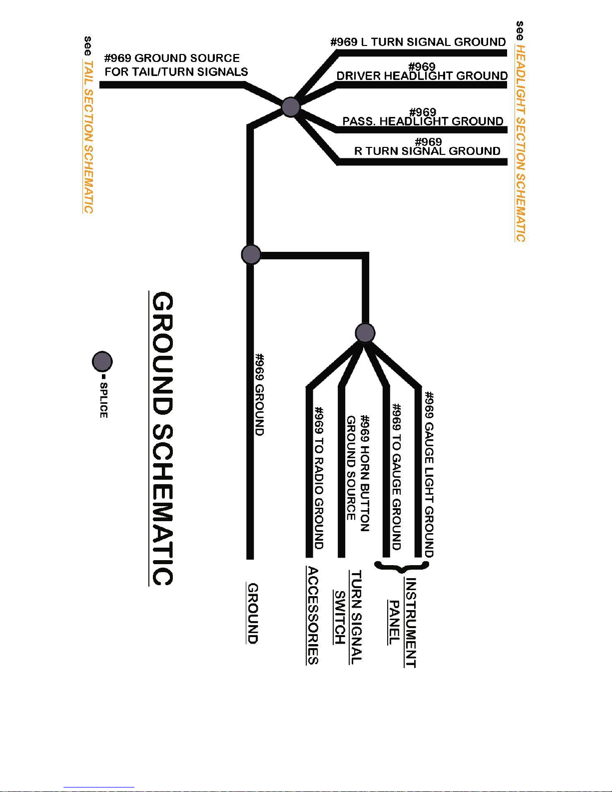
To help avoid grounding problems, all the ground wires in the Painless harness
are connected together through a series of splices. All of these splices connect to a
large 10 gauge wire found in the COMPONENT OUTPUT HARNESS, see the Ground
Schematic on page14.
On light housings that ground through the mounting and for the harness ground
wire connection point make sure that all mounting points are clean by removing all dirt,
corrosion, or paint. This is especially important for cars that have recently been painted
as paint build up will cause grounding issues. 80 grit or courser sandpaper should be all
that’s needed to properly clean grounding points.
Why are clean grounds important?
As an example we will use a front turn signal that also functions as a park light.
Follow the red line from right to left in the diagrams on the next page. This red line
indicates the path electrical current takes when everything is properly grounded and as
represented in the second diagram, when the ground is bad; notice which bulbs
illuminate when good and bad grounds are present.
In our park light example with a good ground source, current travels from the
headlight switch to the park light bulb. Since the bulb is properly grounded, current
12
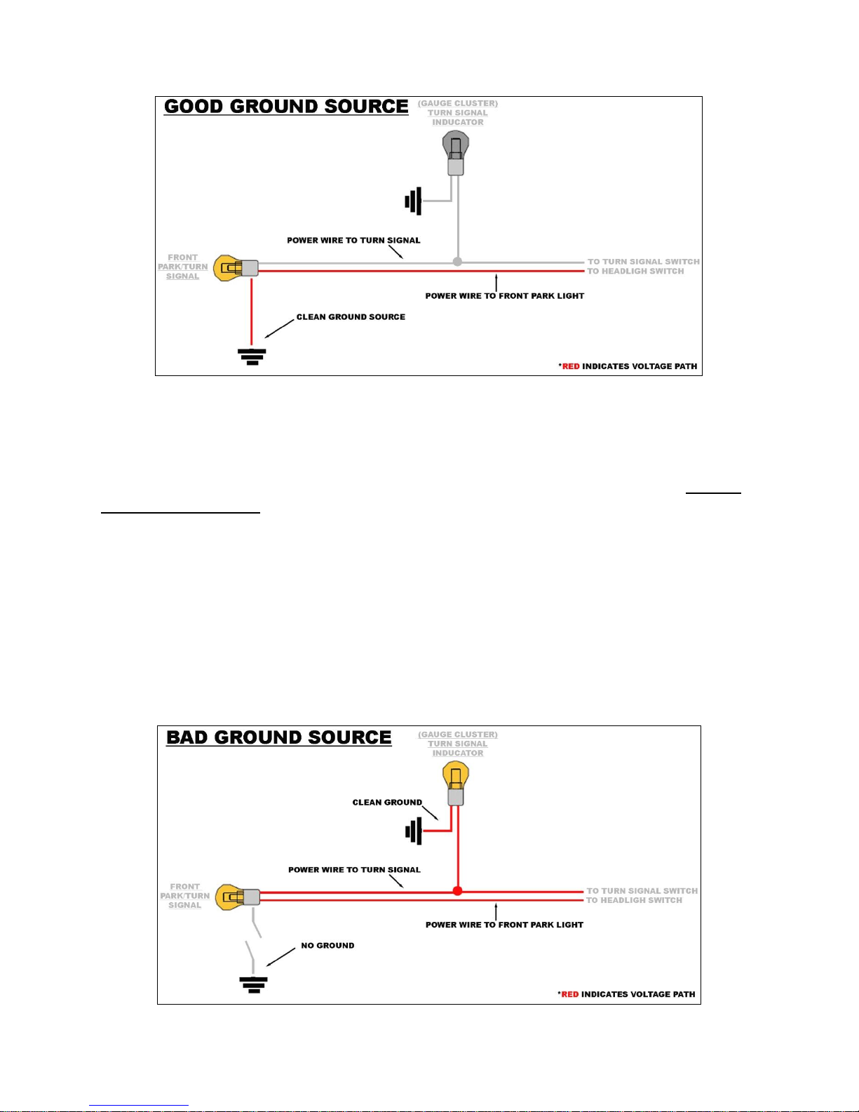
passes cleanly through the bulb causing it to illuminate and the current exits the bulb
through the ground source back to the battery. The ground allows everything to work
properly without any issues.
When a ground isn’t connected or is contaminated with dirt, corrosion, or paint,
the voltage will find the easiest path to ground, which is represented in the diagram
below.
Current travels from the headlight switch to the park light bulb, but wait; there is
no ground at the bulb. Since the ground it would normally use is not there, the current
will find another way to get to ground and back to the battery. When this happens,
things that should not have power receive power coming from the park light bulb. Since
the turn signal wire also goes to the bulb, the current will travel out of the bulb through
the turn signal wire. Notice in the diagram that a bad ground at the front park light can
cause issues on the interior of the vehicle at the turn signal indicator on the dash. In this
case, the turn signal indicator light is illuminated when it shouldn’t be. Also, since this
one power source which was only supposed to power 1 bulb is not powering 2 bulbs,
both bulbs may be dimmer than they would have been if everything was grounded
properly. This is one of the problems with diagnosing a bad ground; they can cause
issues throughout the entire vehicle.
13
14
FUSE BLOCK
The Painless harness contains an 8 circuit fuse block that uses modern ATC
blade style fuses. This fuse block allows the convenience of having both flashers (turn
signal and hazard), as well as the horn relay, to be mounted in one location.
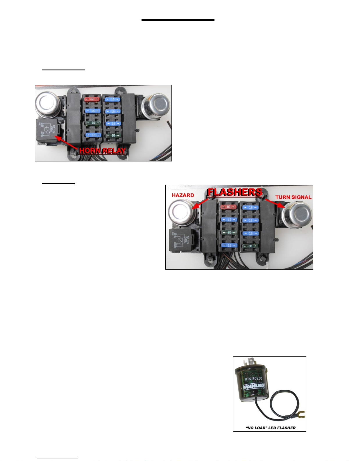
Horn Relay
On the fuse block you will find a horn
relay, which replaces the factory core
support/firewall mounted horn relay found
on older vehicles. The fuse block mounted
horn relay uses a standard 30 amp SPST
relay and is ground activated from a wire in
the Turn Signal Switch group of wires of the
fuse block harness. Replacement relays for
the horn relay can be found at any auto
parts store or by ordering Painless part
number #80131.
Flashers
The two flashers simply switch
power off and on going to the turn
signal switch and hazard switch. The
flasher found next to the horn relay is
the hazard flasher. The flasher on the
side of the fuse block by itself is the
turn flasher.
How a flasher functions is
simple. Power is switched off and on
according to heat built in the resistance wire inside the flasher. As soon as power is
drawn through the flasher, as when the turn signal or hazard switch is activated, the
resistance wire heats up and makes contact with the output side of the flasher. This
contact passes power through the flasher, into the switch and to the turn signal lamp(s).
Once this contact has been made, the resistance wire is no longer resisting any voltage,
so it begins to cool; this cooling causes the flasher to lose contact.
This loss of contact means that there is no longer any voltage going to the
switch, causing the turn signal light to turn off. Once contact is lost, the resistance wire
begins heating up and the entire process starts over again until the turn signal switch or
hazard switch is disengaged.
Some L.E.D. turn signals do not draw enough
voltage to activate a typical thermal flasher. If you are using
L.E.D. turn signals, and your turn signals do not work
properly and you are certain everything is connected
properly, a no load flasher will be required; Painless part
number #80230.
15
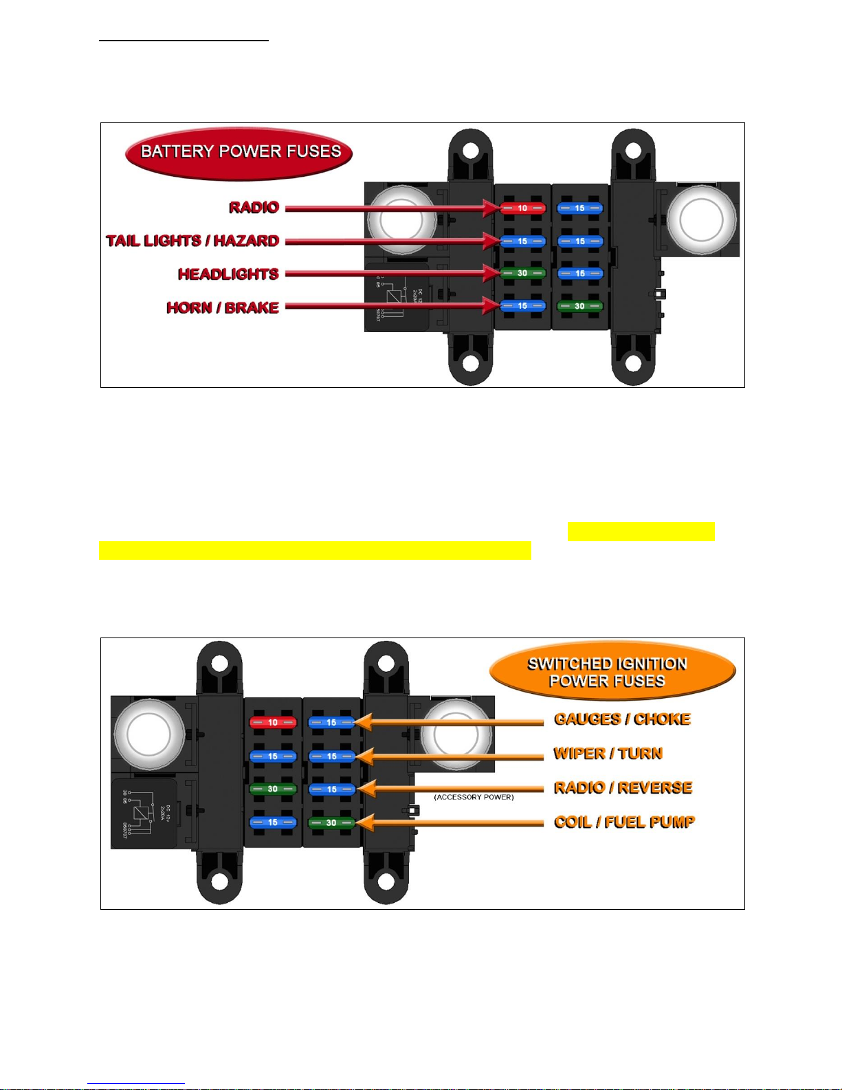
Fuse Identification
The following two diagrams and information will detail each fuse and which
components/circuits each fuse powers.
The drawing above shows all the battery power fuses. These fuses are powered
by a wire that comes from the large power splice, seen on page 53. All of these battery
power fuses fuses will have power at all times.
The drawing below shows all the switched ignition fuses. These fuses are
powered by wires coming from the ignition switch (wires #931, #932, and #933) and will
have power depending on what position the ignition switch is in. None of these fuses
should have power when the ignition is in the OFF position. The “RADIO / REVERSE”
fuse is powered by the wire intended to connect to the accessory terminal on the
ignition switch as noted in the drawing. The ignition switch section, page 79 of the
second manual, will go into further detail about power supplied to these fuses.
Fuse labels have been provided to allow labeling the fuse block for future
reference.
16
Relays and Switches
All ACCESSORY wires found in this harness can support up to 15 amps.
Components requiring more amperage will need to be connected to a relay. An
ACCESSORY wire can be used as a 12 volt activation source or 12 volt source for
ground activation in these circumstances. Take a look at Painless part #’s 30107 &
30108 to fill your relay needs.
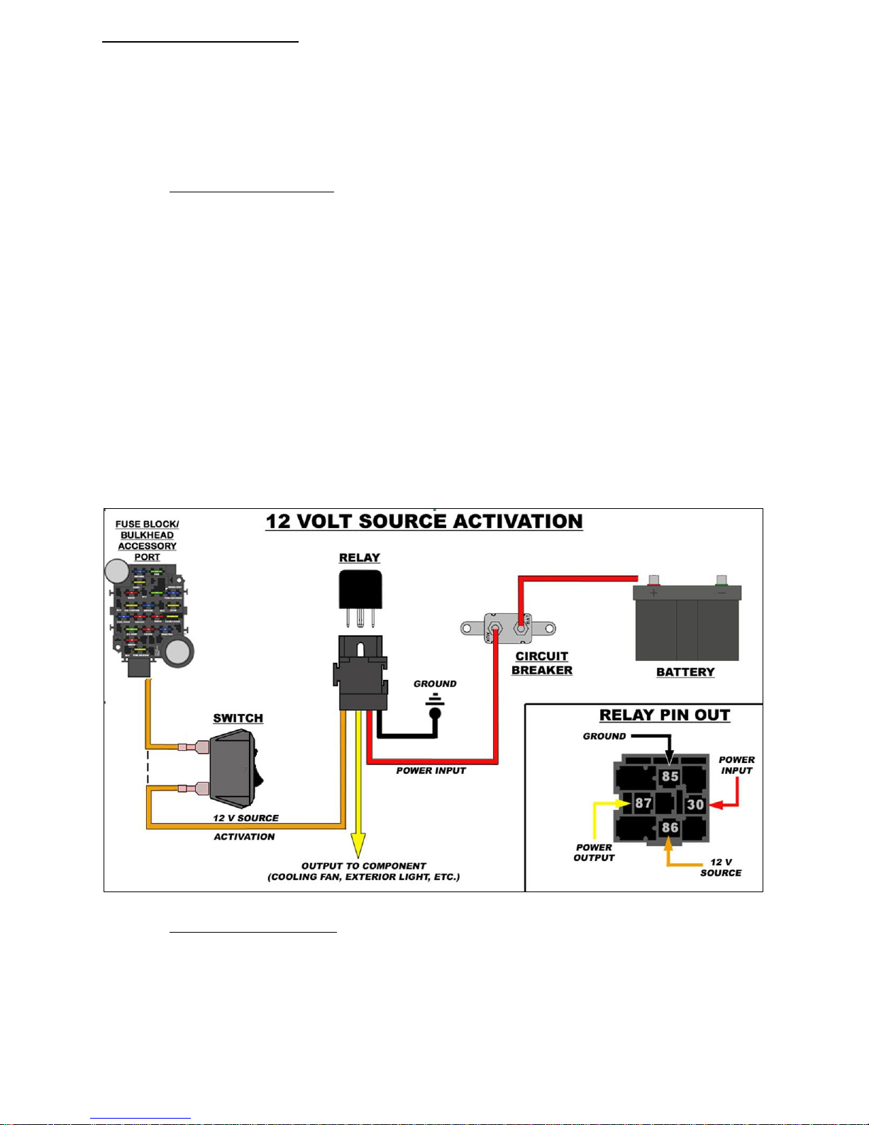
A 12 volt activated relay is constantly grounded and will send power out of the
output side of the relay to the component being powered when 12 volts is applied to the
relay, as the name implies. The 12 volt source can be wired directly to the relay or
interrupted by a switch, as shown in the 12 VOLT SOURCE ACTIVATION drawing.
Wiring directly to the relay, as indicated by the dashed line, would be used in the
case of wiring a water pump relay, or any other high amperage component you
would want to run continuously while the key is in the on position. In these cases,
make certain the 12 volt wire you are using is an Ignition Switched 12 volt wire and
not a battery constant hot.
The 12 volt activation wire can also be wired to a switch to offer the user OFF/ON
capabilities. These are the situations a battery constant power source would be
used. This would allow a component to be turned OFF or ON without the key in the
ON position. However, unless a lighted switch is being used, a ground activated
relay may work better to avoid running power through the switch.
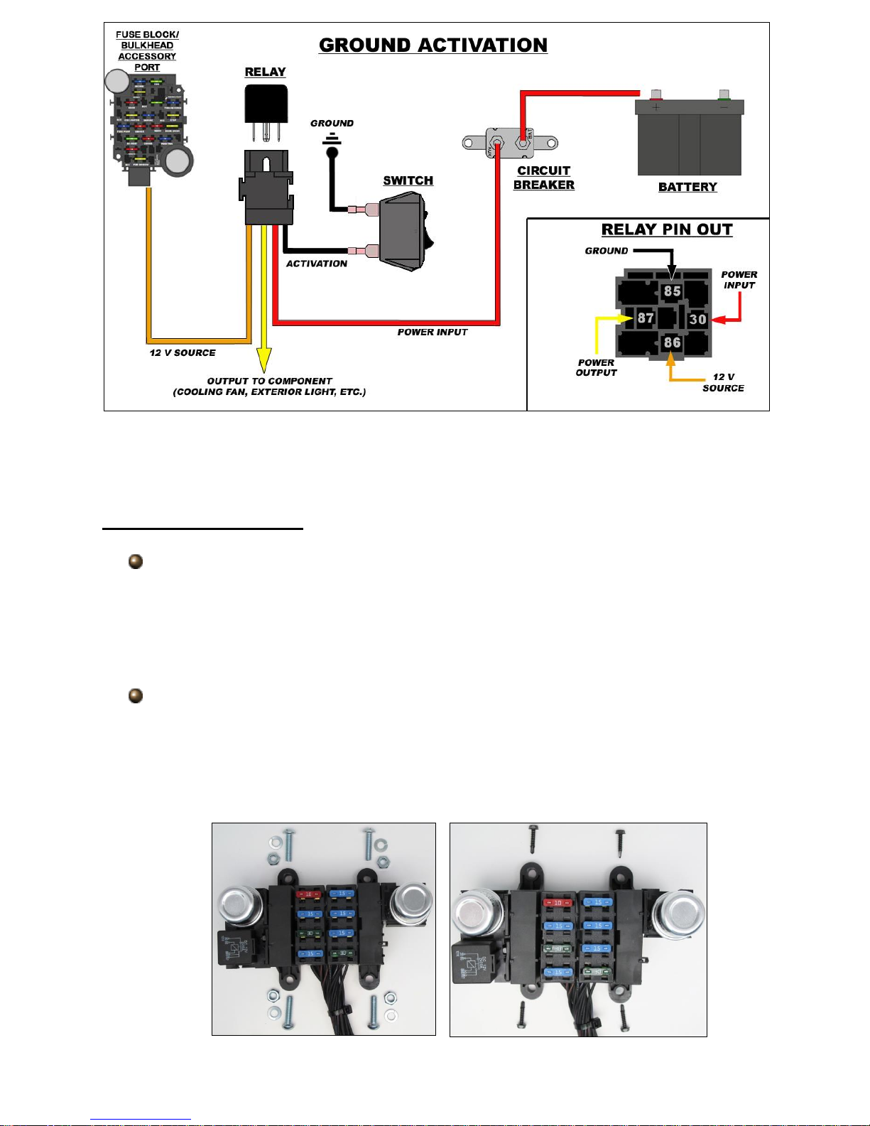
A ground activated relay is just the opposite of the 12 volt activated relay, 12
volts (battery constant or switched) is supplied uninterrupted and the ground wire is
switched. The Horn Relay pre-wired in the Painless harness is a Ground Activated
Relay. Another example of this method is a thermostat operated fan relay. In this case
however, a thermostatic switch would replace the switch in the drawing below. Like
mentioned before, ground activation method is best used when a component is
operated by an unlit switch from the interior of the vehicle.
17
In the event that a toggle/rocker switch is being used without a relay, make sure
the amperage of the component you are powering does not exceed the capabilities of
the switch. Switch failure will occur.
Fuse Block Mounting
Locate the harness with the fuse block pre-installed.
To begin mounting the fuse block, you will need to find a suitable location that will
allow easy access in the event you have to replace a fuse, and also allow enough
length for the wires to reach things like the ignition switch, headlight switch, etc. Make
sure this area in out of the elements and in an area that will not get wet.
Mount the fuse block to the mounting location in one of the following 2 ways:
1) Drilling holes using a ¼” drill bit and using the four bolts, nuts and washers
supplied
2) Using the four self tapping screws and a ¼” nut driver on a drill.
18
19
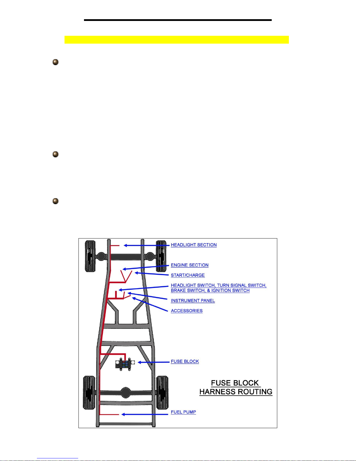
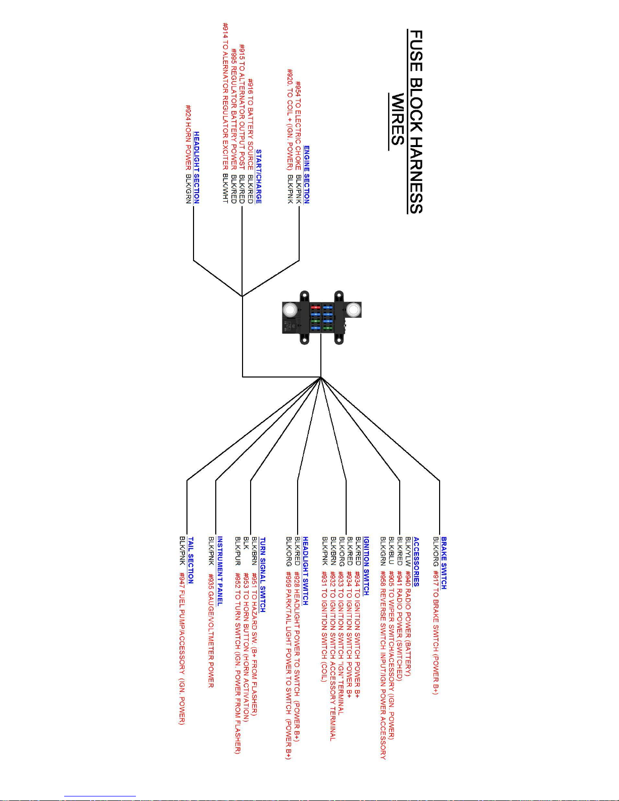
FUSE BLOCK HARNESS ROUTING
Loosely route all of the following wire groups to their designated connection
points. NO CONNECTIONS OR CUTTING WILL TAKE PLACE AT THIS TIME. A
complete layout of the Fuse Block Harness can be found on the previous page.
Route the 3 sections intended for engine compartment connection towards the
front of the vehicle. These sections are labeled “ENGINE SECTION”,
START/CHARGE, and HEADLIGHT SECTION”.
Multiple grommets have been provided to allow pass through of the firewall/floor
board. Use the grommet that best fits an existing hole or one created by you, the
installer.
If you are using a hydraulic brake switch mounted on or near the master cylinder,
the wire labeled “BRAKE SWITCH” will also be grouped and routed with these
wires.
Route the wires intended for dash mounted components/switches towards their
connection points on the dash at this time. These will be groups labeled “TURN
SIGNAL SWITCH”, “HEADLIGHT SWITCH”, “IGNITION SWITCH”,
“ACCESSORIES”, “INSTRUMENT PANEL”, AND “BRAKE SWITCH” (if it wasn’t
already routed to the engine compartment)
A single wire labeled “TAIL SECTION” is a power wire intended to connect to an
electric fuel pump or wire can also be used for something else, can be routed at
this time to its connection point. See page 95 of the second manual for more
information on this wire.
20
21
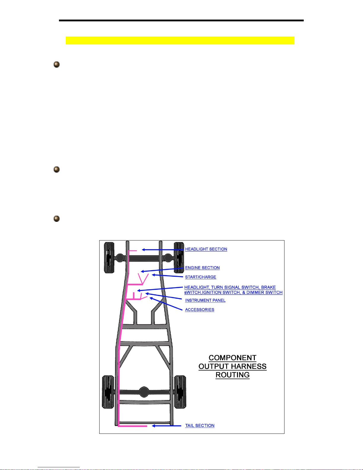
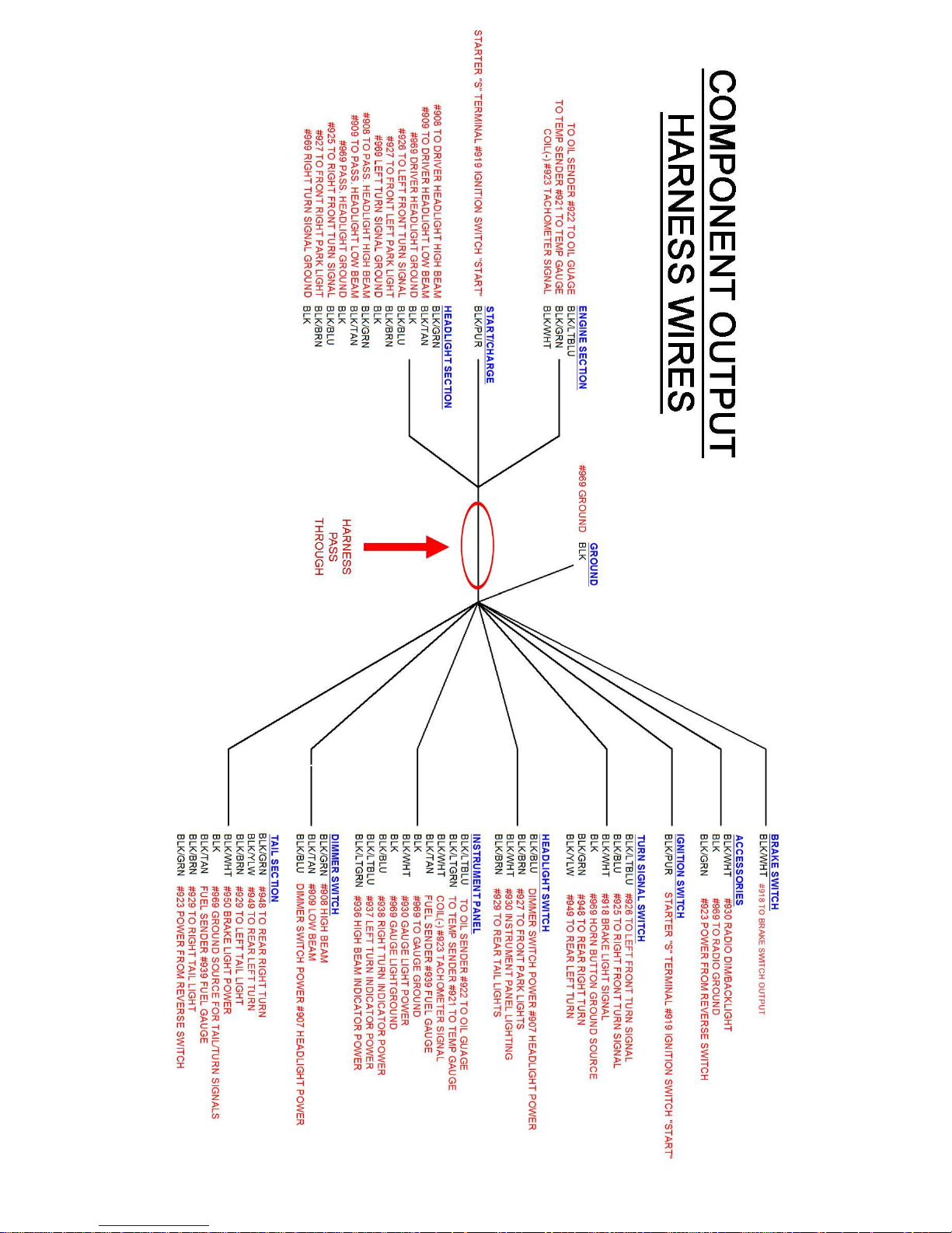
COMPONENT OUTPUT HARNESS ROUTING
Loosely route all of the following wire groups to their designated connection
points. NO CONNECTIONS OR CUTTING WILL TAKE PLACE AT THIS TIME. A
complete layout of the Component Output Harness can be found on the previous page.
On the Component Output harness, locate the area seen circled in red in the
schematic on the previous page. This area will be the portion of the Component
Output Harness that passes through the firewall/floor board towards the front of
the vehicle.
At this time route the following groups of wires towards their locations in the front
of the vehicle: “ENGINE SECTION”, START/CHARGE, and HEADLIGHT
SECTION”
If you are using a hydraulic brake switch mounted on or near the master cylinder,
the wire labeled “BRAKE SWITCH” will also be grouped and routed with these
wires.
Route the wires intended for dash mounted components/switches towards their
connection points on the dash at this time. These will be groups labeled “TURN
SIGNAL SWITCH”, “HEADLIGHT SWITCH”, “IGNITION SWITCH”,
“ACCESSORIES”, “INSTRUMENT PANEL”, AND “BRAKE SWITCH” (if it wasn’t
already routed to the engine compartment)
Route the large bundle of wires labeled “TAIL SECTION” to the rear of the
vehicle.
22
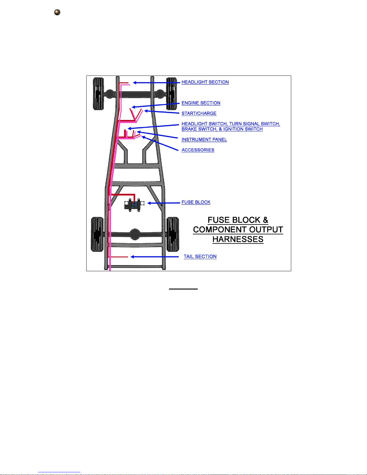
With both harnesses now routed you can begin using the small 4” zip ties
provided in the kit to tie the two harnesses together to create one harness. The
drawing below shows that if routed correctly both harnesses should be close , if
not side by side or one top of each other, making tying them together rather
easy. If your harnesses are routed on different sides of the vehicle, tie the
harnesses together where they meet at common connection points, such as the
dash mounted switches.
NOTES
23
HEADLIGHT SECTION CONNECTIONS
The HEADLIGHT SECTION of this Painless Harness includes all power and
ground wires needed to properly hook up both driver and passenger side headlights,
and left and right front turn & park/marker lights. There is also a power wire from the
fuse block mounted horn relay to power a horn. All wires in the Headlight Section can
be seen in the Headlight Section Schematic on page 30.
Left/Driver Side Headlamp
Your first connection in the Headlight Section will be the Left/Driver side
Headlamp. Three wires make up the connection to the Left Headlamp, they are:
Black/Green: 14 gauge wire, printed [HEADLIGHT SECTION] #908 TO DRIVER
HEADLIGHT HIGH BEAM, this wire will provide power to the high beam filament of the
head lamp. This wire goes into a splice with a wire going to the right headlamp and also
to a wire going to the high beam indicator in the dash and to the dimmer switch. This
wire will have power when the dimmer switch is in the high beam position and the
headlight switch is in the headlight ON position.
Black/Tan: 14 gauge wire, printed [HEADLIGHT SECTION] #909 TO DRIVER
HEADLIGHT LOW BEAM, this wire will provide power to the low beam filament of the
head lamp. This wire goes into a splice with a wire going to the right headlamp and also
to a wire going to the dimmer switch. This wire will have power when the dimmer switch
is in the low beam position and the headlight switch is in the headlight ON position.
Black: 14 gauge wire, printed [HEADLIGHT SECTION] #969 DRIVER HEADLIGHT
GROUND , this wire provides a ground source for the headlamp. This wire is tied into
the integrated ground circuit and can be seen in the Ground Schematic on page 14.
24
The connection of these three wires will depend on the style headlights you are
using in your application…
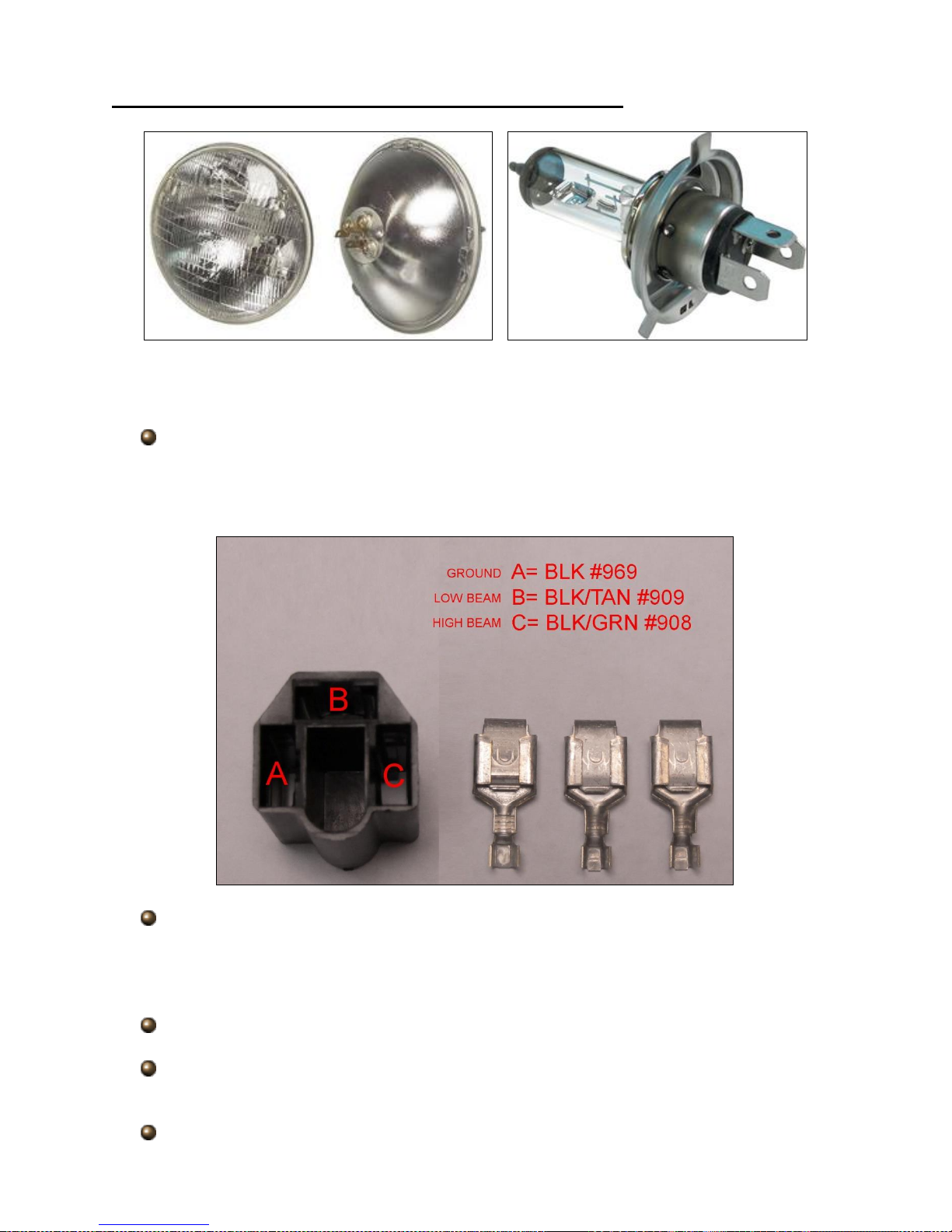
3 prong, Sealed Beam/ Sealed Beam Halogen/ H4 halogen
Connectors and terminals have been provided in the parts kit to allow proper
connection to these 3 prong headlights.
Locate the terminals and connector seen in the photo below. Please be aware
these terminals look just like smaller narrower terminals provided in the kit; you
will need the larger terminals for this connection. These terminals will be in the
same compartment as the connectors.
Route the 3 wires for left/driver side headlamp connection to the back of the
headlamp. Removing the headlamp may be necessary and is recommended to
ensure the terminals of the headlamp are not damaged during connection; they
are easily bent if the connector is not installed correctly.
Cut the 3 wires to length and strip ¼” of insulation from all 3 wires.
Using a set of roll over crimpers, as shown on page 11, crimp a terminal onto
each wire.
Insert all three wires in the connector according to photo above.
25
Plug the connector onto the prongs of the headlamp. Make sure the connector is
inserted straight onto the prongs as these prongs will easily bend making a
proper connection difficult.
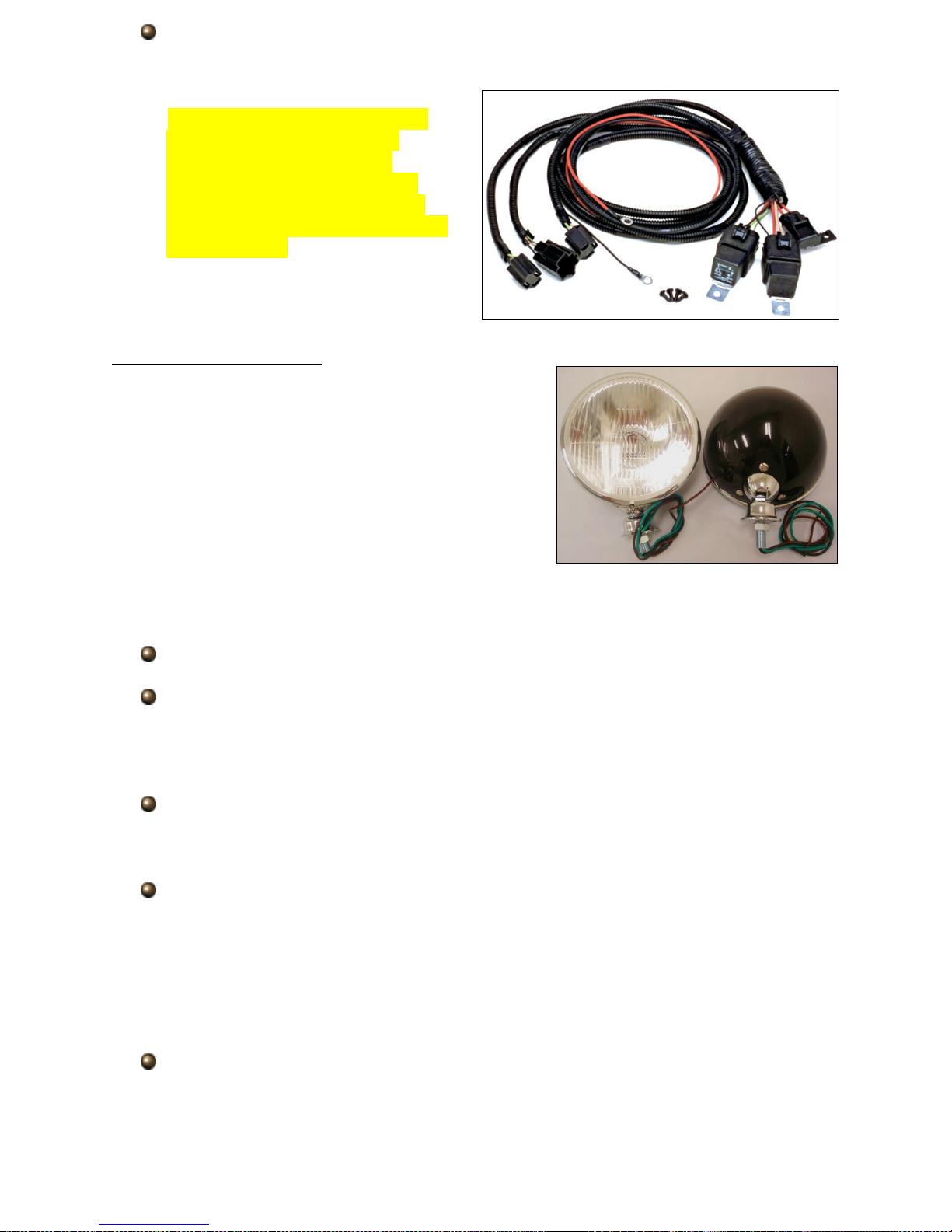
If halogen bulbs are being used
Painless recommends using
Painless part # 30815. This
headlight relay kit is needed to
avoid overloading the headlight
switch with the higher demands of
halogen bulbs.
Headlights with Pigtails
In order to make the appropriate connections
consult the manufactures instructions of the
headlights you are using to identify each wires
function. If you do not have instructions, or know
the manufacturer of the lights on your vehicle, you
can test a light using your vehicles battery.
On units that have 3 wires, in almost all
cases there will be a black wire, this is typically a
ground, while the other two colored wires are obviously the power for the high and low
beams. Units with 5 or 6 wires also have turn/park light features.
Touch one of the colored wires to the positive side of the battery.
With the colored wire touching the positive side, now touch the black wire, or both
black wires if your lamp also has turn/park, to the negative side. You may see a
couple sparks upon connecting to the negative side but this is normal. The light
should now be on, take notice to how bright the light is.
Remove both wires from the battery and repeat this process with the other
colored wire(s). First to the positive side, and then the ground(s) to the negative
side.
Whichever wire on the positive side on the battery made the light(s) brighter is
the high beam power wire or turn signal if your lamps have this option. Write this
down in the notes section at the back of this manual for future reference.
In some cases headlamps will have a Green, Brown or Tan, and Black wire
coming from them, like shown in the photo above. This is a common GM style color
code meaning: Black = ground, Brown or Tan= low beam, Green= high beam.
Connection of the #908, #909, & #969 wires of the Painless harness will be made
using the nickel plated splices provided in the parts kit along with pieces of heat
shrink.
26
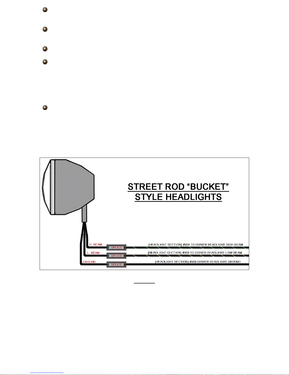
Each wire, coming from the headlight bucket as well as the Painless Harness will
be cut to length and have ¼” of insulation stripped from them.
Connect the splice to each of the 3 wires on the Painless harness, taking the split
on the splice into consideration as shown on page 8.
With the splice crimped, slide a piece of heat shrink onto each wire.
Insert the wires from the headlight bucket into the splice that corresponds with
the wires function:
High Beam wire to the Painless Black/Green wire printed #908
Low Beam wire to the Painless Black/Tan wire printed #909
Ground wire to the Painless Black wire printed #969
With the wires now crimped, slide the heat shrink over the splice and apply heat
with a heat gun* to shrink it down and make a weather resistant connection.
*Some may opt to use a small soldering torch or even a cigarette lighter to
accomplish this. This is not advised as it tends to overheat the heat shrink
causing it to bubble or crack. Use caution to prevent overheating if using any kind
of flame.
NOTES:
27

“Left Turn/Park Light”
The Left Turn/Park Light of the
Painless harness consists of 3 wires,
These wires are:
Black/Brown: 18 gauge wire, printed
[HEADLIGHT SECTION] #927 TO
FRONT LEFT PARK LIGHT, is the power
source for the park light. This wire is
spliced to the other #927 wire in the Head
Light Section and also with a #927 wire
going to the Headlight Switch. This wire
will have power anytime the headlight switch is in the Park/Tail Lights ON or Headlights
ON position.
Black/Light Blue: 18 gauge wire, printed [HEADLIGHT SECTION] #926 TO LEFT
FRONT TURN SIGNAL, this wire is the turn signal power. This wire goes into a splice
with the Black/Light Blue wires going to the left turn indicator light and to the wire
coming from the turn signal switch. This wire will have interrupted switched power from
the turn signal flasher any time the left turn signal is activated and the ignition is in the
ON position and interrupted battery power from the hazard flasher any time the hazard
switch is in the ON position.
Black: 18 gauge wire, printed [HEADLIGHT SECTION] #969 LEFT TURN SIGNAL
GROUND, this wire provides a ground source for the turn/park lamp. This wire is tied
into the integrated ground circuit and can be seen in the Ground Schematic on page 14.
If your light has a dual filament bulb and only 2 wires, you will not connect the
black #969 wire. Your light socket grounds though the mounting of the lens/bucket. If
this is the case, #969 can be removed from the harness or connected to the frame or
any other clean ground source.
If your light has a single filament bulb, your lens will only act as a turn signal.
#927 will not have a connection point; check your local laws to see if front park lights
are required, you could be in violation of the law without them. If you can run without the
front park lights, both #927 wires, along with the other wire going to the headlight switch
splice to these can be removed from the Painless harness
The #926, #927, & #926 will be connected to the wires coming from the Turn
/Park light with splices and heat shrink. If you are unsure of which wires is the
park light and turn signal, follow the instructions given on page 25 for testing the
function of each wire. The brighter of the two functions (park and turn signal) will
be the turn signal function. If your lens or bucket only has 2 wires and is a dual
filament bulb, the testing will have to be done with the lens/ bucket mounted to
the vehicle for proper grounding.
NOTES
28
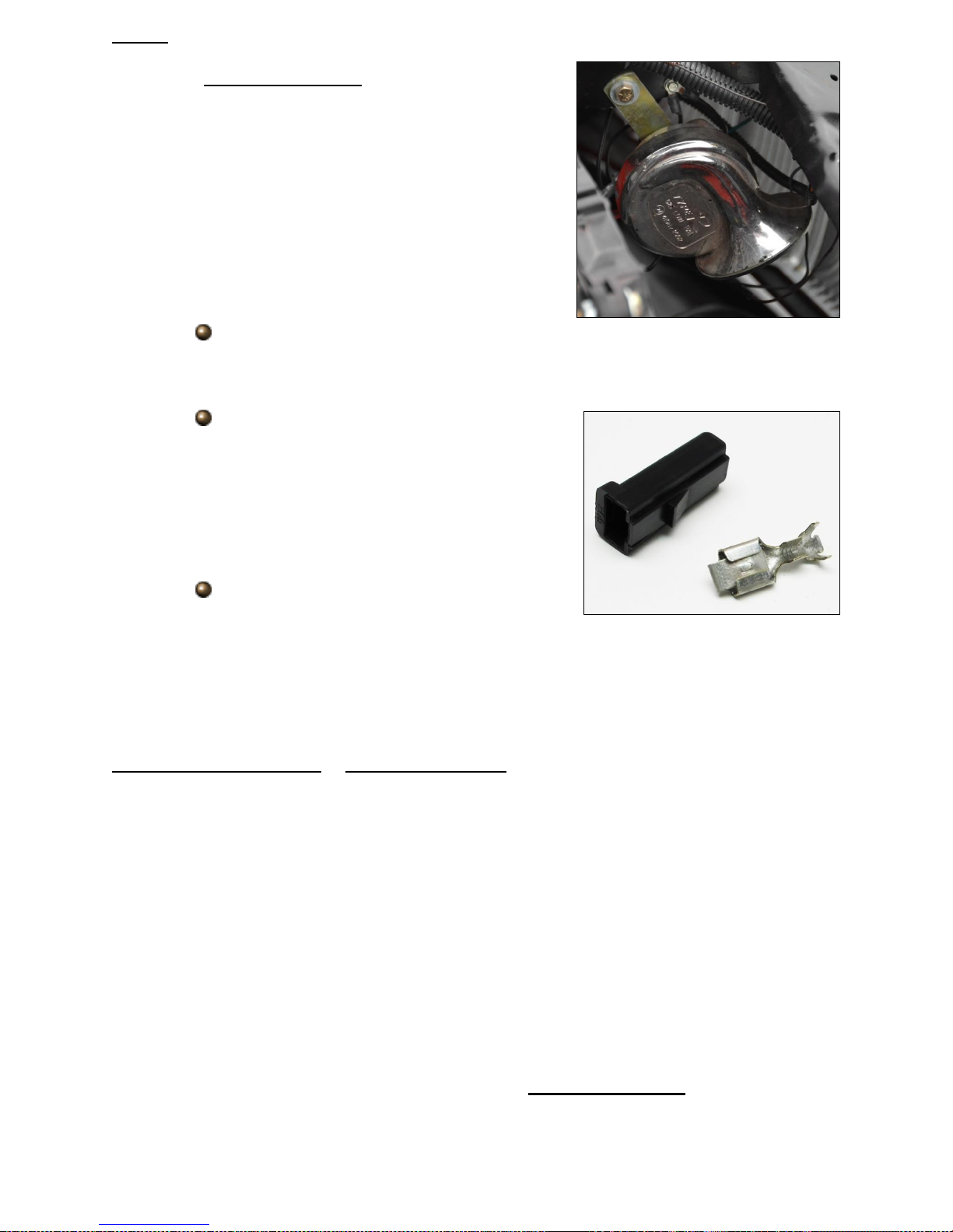
“Horn”
The Headlight Section has a single wire
dedicated for connection to a horn. *Most horns
ground through their mounting and only require a
power connection. This wire is:
Black/Green: 16 gauge wire, printed [HEADLIGHT
SECTION] #924 HORN POWER, this is a power wire
that comes from the fuse block mounted horn relay
which is ground activated by the horn button on the
steering column. This wire will only have power when
the horn button is pressed.
Route the #924 wire to the horn. If you have to pass this wire through any
metal surfaces, you will find small grommets in the parts kit to protect the
wire.
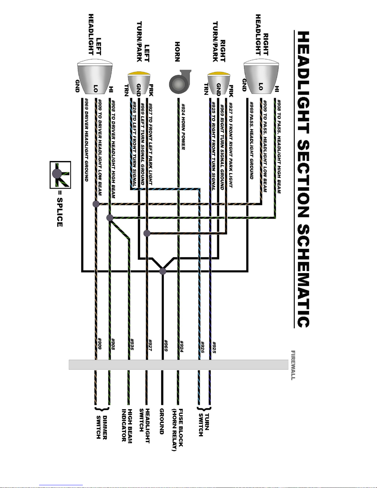
If you have a tab on the horn, locate the
terminal and connector, seen to the right,
provided in the parts kit.
Ring terminals and heat shrink have been
provided for those with “screw” or “post &
nut” connections.
If your horn has a wire to connect to, then
a splice and heat shrink will be needed.
*If your horn requires a ground wire, use a piece of scrap wire that was cut from
the any of the black #969 ground wires on the driver side headlight or turn/park light
connections to connect the ground on the horn. Using a ring terminal from the parts kit,
attach the other end of the ground wire to a chassis ground source on the vehicle.
“Right Turn/Park Light” & “Right Headlamp”
The connections mentioned above all connect in the same manner as those on
the left/driver side. The only difference you will find is the Turn signal wire for the right
turn signal has a different color stripe that one used for the left turn signal. The right
Turn signal will be:
Black/ Blue: 18 gauge wire, printed [HEADLIGHT SECTION] #925 TO RIGHT FRONT
TURN SIGNAL, this wire is the turn signal power. This wire goes into a splice with the
Black/ Blue wires going to the right turn indicator light and to the wire coming from the
turn signal switch. This wire will have interrupted switched power from the turn signal
flasher any time the left turn signal is activated and the ignition is in the ON position and
interrupted battery power from the hazard flasher any time the hazard switch is in the
ON position.
This concludes all of the connections in the Headlight Section of the engine
harness. Go back and inspect the harness layout and once satisfied it is free of moving
parts and sharp edges tighten any loose zip ties.
29
30
 Loading...