

Page 1

TubeHead
Model 9305
Assembly and Using Manual
If you love vacuum tubes, here’s a device that’s
got your name on it. The TubeHead is a low-cost,
two-channel vacuum tube pre-amplifier with a
twist. The twist is that this circuit is designed
to be adjustable from crisp solid-state
transparency to an exaggerated caricature of tube
amp warmth. In between these extremes, you’ll
find tonal coloring options than you’ve never had
before and sounds that mimic every tube amp you
ever heard. This circuit is so versatile that you
may use it in place of compressors, limiters and
sustainers even though, technically, it is none of
these.
(c) 1993 PAiA Electronics, Inc.
Portions of this document are excerpted from
an article in the December 1993 issue of
Electronic Musician magazine, copyright 1993,
and are reprinted by permission of the Publisher.
TubeHead 1
Page 2

ASSEMBLING THE TubeHead
Before beginning assembly, go through the manual.
Look at the drawings. Feel the parts. You’re
naturally eager to plunge right in, but take a few
deep breaths first.
Notice that each step in the manual is marked with
a checkoff box like this:
DESIGNATION VALUE COLOR CODE
( ) R27 100 ohm brown-black-brown
Checking off each step as you do it may seem
silly and ritualistic, but it greatly decreases the
chance of omitting a step and also provides
some gratification and reward as each step is
completed.
Numbered figures are printed in the Illustrations
Supplement in the center of this manual. These pages
may be removed for easy reference during assembly.
THE CIRCUIT BOARD
The TubeHead is built on a single-sided circuit
board. Before beginning assembly, clean oxidation
from the copper side of the circuit board using
scouring cleanser and water. The copper should be
bright and shiny before beginning assembly.
Once you begin putting parts on the circuit board,
it’s a good idea to continue until all the parts
are mounted. Stopping overnight may allow the
copper to oxidize and make soldering more difficult.
TOOLS
You’ll need a minimum of tools to assemble the kit
- a small pair of diagonal wire cutters and pliers,
screwdriver, sharp knife, ruler, soldering iron and
solder.
Modern electronic components are small (in case you
hadn’t noticed) and values marked on the part are
often difficult to see. Another handy tool for
your bench will be a good magnifying glass. Also
2 TubeHead
Page 3

use the magnifier to examine each solder joint as
it is made to make sure that it doesn’t have any of
the problems described in the SOLDERING section
which follows.
SOLDERING
Select a soldering iron with a small tip and a
power rating not more than 35 watts. Soldering
guns are completely unacceptable for assembling
solid state equipment because the large magnetic
field they generate can damage components.
Use only rosin core solder (acid core solder is for
plumbing, not electronics work). A proper solder
joint has just enough solder to cover the soldering
pad and about 1/16-inch of lead passing through it.
There are two improper connections to beware of:
Using too little solder will sometimes result in a
connection which appears to be soldered when
actually there is a layer of flux insulating the
component lead from the solder bead. This
situation can be cured by reheating the joint and
applying more solder. If too much solder is used
on a joint there is the danger that a conducting
bridge of excess solder will flow between adjacent
circuit board conductors forming a short circuit.
Accidental bridges can be cleaned off by holding
the board upside down and flowing the excess solder
off onto a clean, hot soldering iron.
Use care when mounting all components. Never force
a component into place.
TubeHead 3
Page 4
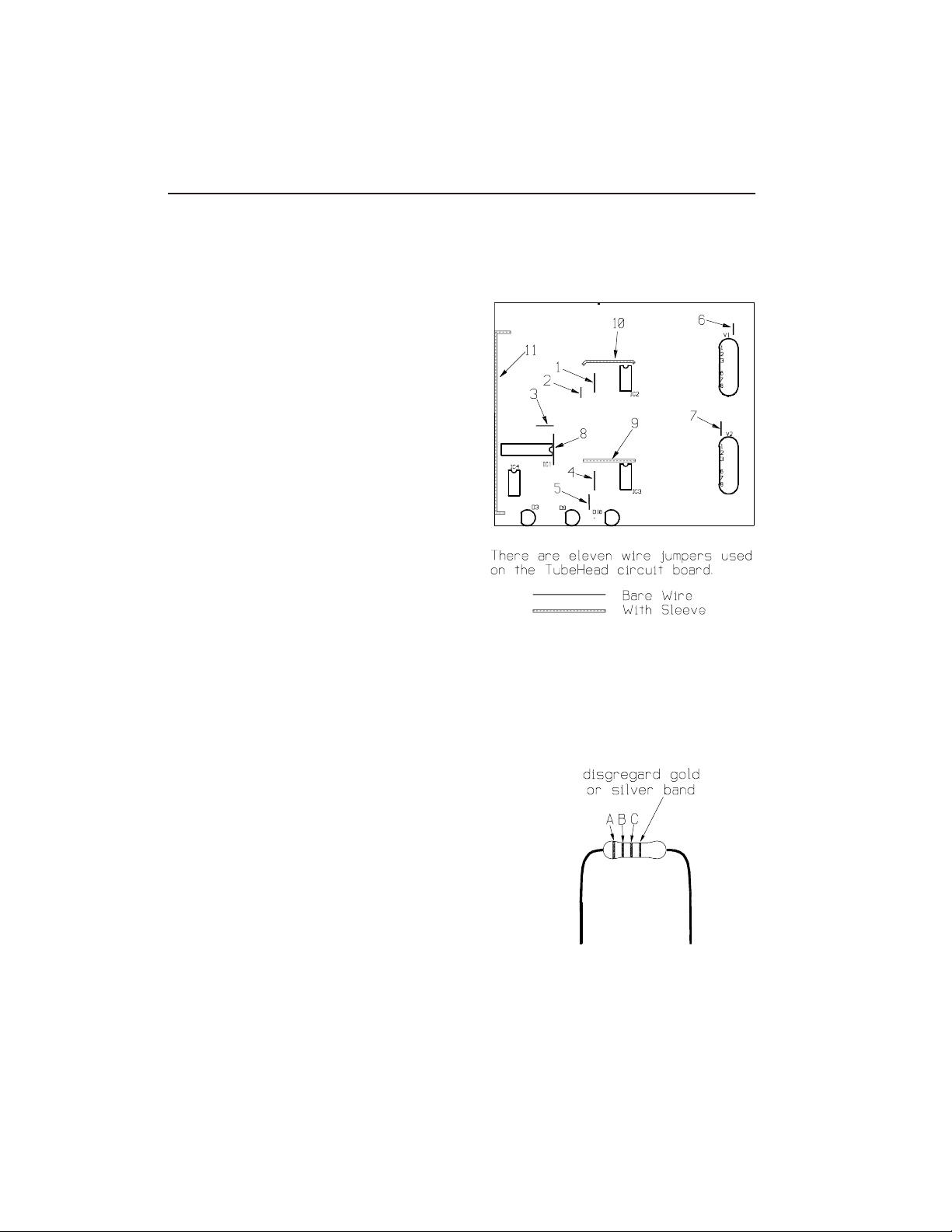
WIRE JUMPERS
Assembly begins by forming and installing the
eleven wire jumpers indicated by bold lines on the
circuit board parts placement designators and the
illustration to the right. For each jumper,
cut a length of the bare wire supplied by
measuring it against the distance between the
circuit board holes and adding about 1/2". Bend
1/4" of each end down and push through the circuit
board holes. Press the jumper fully against the
board and solder both ends. Trim off excess wire
flush with the solder joint.
Notice that three of the jumpers will be covered
with the insulating sleeving provided. Cut a
piece of sleeving slightly shorter than the
distance between the holes and slip it over the
jumper before bending the wire ends down and
placing.
( ) As outlined above, form and install the
eleven wire jumpers used on the circuit
board.
RESISTORS
Solder each resistor in place following the
parts placement designators printed on the circuit
board and the assembly drawing Fig 1. Note that
resistors are nonpolarized and may be mounted with
either lead in either of the corresponding holes.
Before mounting each resistor, bend its leads so
that they are at a right angle to the body of the
part. Put the leads through the holes and then
push the resistor firmly into place. Cinch the
resistor in place by bending the leads on the
solder side of the board out to an angle of about
45 degrees. Solder both ends of each resistor in
place as you install it. Clip each lead flush
with the solder joint as the joint is made.
4 TubeHead
Page 5

DESIGNATION VALUE COLOR CODE A-B-C
( ) R1 100 ohm brown-black-brown
( ) R3 100 ohm brown-black-brown
( ) R4 33K orange-orange-orange
( ) R5 33K orange-orange-orange
( ) R12 22K red-red-orange
( ) R22 330 ohm orange-orange-brown
( ) R27 150K brown-green-yellow
( ) R28 8200 grey-red-red
( ) R29 1K brown-black-red
( ) R40 22K red-red-orange
( ) R50 330 orange-orange-brown
( ) R55 150K brown-green-yellow
( ) R56 8200 grey-red-red
listed below: 10K brown-black-orange
( ) R6 ( ) R30 ( ) R33
( ) R34 ( ) R61
listed below: 100K brown-black-yellow
( ) R9 ( ) R37 ( ) R62
( ) R63
listed below: 270K red-violet-yellow
( ) R10 ( ) R11 ( ) R38
( ) R39
listed below: 82K grey-red-orange
( ) R13 ( ) R14 ( ) R41
( ) R42
listed below: 470K yellow-violet-yellow
( ) R17 ( ) R25 ( ) R45
( ) R53
listed below: 47K yellow-violet-orange
( ) R19 ( ) R21 ( ) R26
( ) R47 ( ) R49 ( ) R54
TubeHead 5
Page 6
DESIGNATION VALUE COLOR CODE A-B-C
listed below: 2700 red-violet-red
( ) R31 ( ) R32 ( ) R59
( ) R60
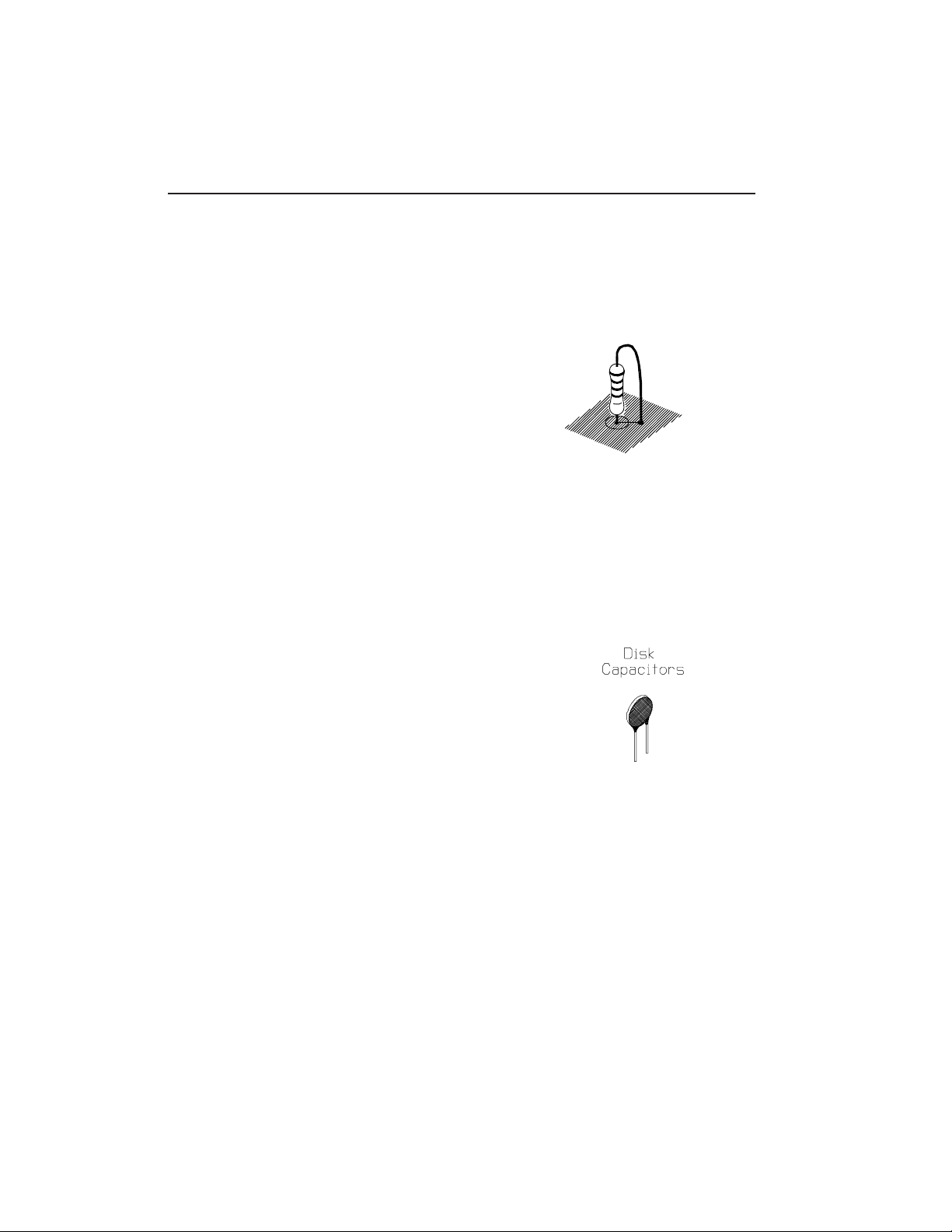
The following resistors are installed vertically
on the circuit board.
( ) R2 330 ohm orange-orange-brown
( ) R57 100 ohm brown-black-brown
( ) R58 100 ohm brown-black-brown
CERAMIC DISK CAPACITORS
Some of the capacitors used in the TubeHead are
non-polarized ceramic disks, either lead can go in
either of the holes on the circuit board. Leads
are already parallel to one another but still may
need to be bent slightly to match the spacing of
the circuit board holes. Like the resistors, push
the leads through the holes in the board and push
the part against the circuit board as far as it
wants to go. Don’t force it, it’s OK if it sits a
little off the board.
Capacitors are often marked with obscure codes
that indicate their values. The 1, 2 or 3 digit
number that specifies value may be preceded or
followed by letters indicating such things as
tolerance. If you get confused about which
capacitors are which, it may help to group them by
same type and check them against quantities on the
packing list at the end of this manual.
DESIGNATION VALUE MARKING
( ) C7 220 pF 221
( ) C11 .01 uF 103
( ) C14 20 pF 20
( ) C16 5 pF 5
( ) C20 .05 uF 503
( ) C21 .01 uF 103
( ) C24 20 pF 20
( ) C26 5 pF 5
6 TubeHead
Page 7
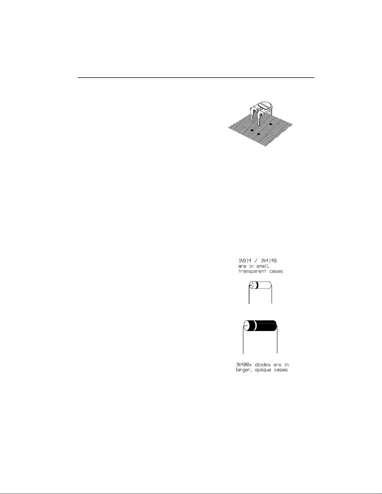
TRIMMER POTENTIOMETERS
Mount the two trimmer potentiometers by inserting
their three pins into the holes provided. Press
them down until the “shoulders” of the solder pins
are resting on the surface of the circuit board.
Solder all three pins on each part
DESIGNATION VALUE
( ) R23 100K
( ) R51 100K
DIODES
Two types of diodes are used in the TubeHead, five
1N4148 silicon signal diodes in small transparent
glass cases and two 1N400x power diodes in larger
opaque cases.
Unlike the previous components, diodes are
polarized and must be installed so that the lead
on the banded end of the part corresponds to the
banded end of the designator on the circuit board.
Bend the leads so they are at right angles to the
body of the part and insert them through the holes
provided in the circuit board.
Diodes are also somewhat heat sensitive so the
soldering operation should be done as quickly as
possible.
DESIGNATION VALUE
( ) D1 1N4001, 1N4002 or 1N4003
( ) D2 “ “ “
listed below: 1N4148 or 1N914
( ) D4 ( ) D5 ( ) D6
( ) D7 ( ) D8
ELECTROLYTIC CAPACITORS
TubeHead 7
Page 8
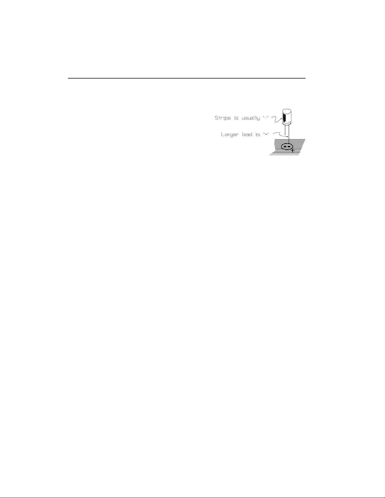
The remaining capacitors are electrolytic types.
Like the diodes, electrolytic capacitors are
polarized and the leads are not interchangeable.
Leads are marked “+” and/or “-” and the “+” lead
must go through the “+” hole in the circuit board.
Frequently the positive lead of the capacitor is
significantly longer than the negative lead.
Usually the Negative lead of the capacitor is
marked rather than the positive. It naturally goes
through the hole not marked “+”.
Capacitors supplied with specific kits may have a
higher Voltage (V) rating than the minimum
specified below.
DESIGNATION VALUE
( ) C1 100 uF /25v.
( ) C2 1000 uF /16v.
( ) C3 100 uF /25v.
( ) C4 1000 uF /16v.
( ) C17 2.2 uF /25v.
( ) C27 2.2 uF /25v.
listed below: 33 uF /25v.
( ) C5 ( ) C6 ( ) C8
( ) C9 ( ) C10 ( ) C19
( ) C29
listed below: 1 uF /50v.
( ) C12 ( ) C13 ( ) C15
( ) C18 ( ) C22 ( ) C23
( ) C25 ( ) C28
INTEGRATED CIRCUITS
Of all the parts, the ICs are the most easily
damaged and should be treated with some respect.
In particular, they may be destroyed by discharges
of static electricity. Modern ICs are not nearly
as sensitive to this kind of damage as were
8 TubeHead
Page 9
earlier versions, but it is still good practice to
handle these parts as little as possible. Also
good practice: don’t wear nylon during assembly.
Don’t shuffle around on the carpet immediately
before assembly (or if you do, touch a lamp or
something to make sure you’re discharged). Don’t
be intimidated. It’s rare for parts to be damaged
this way.
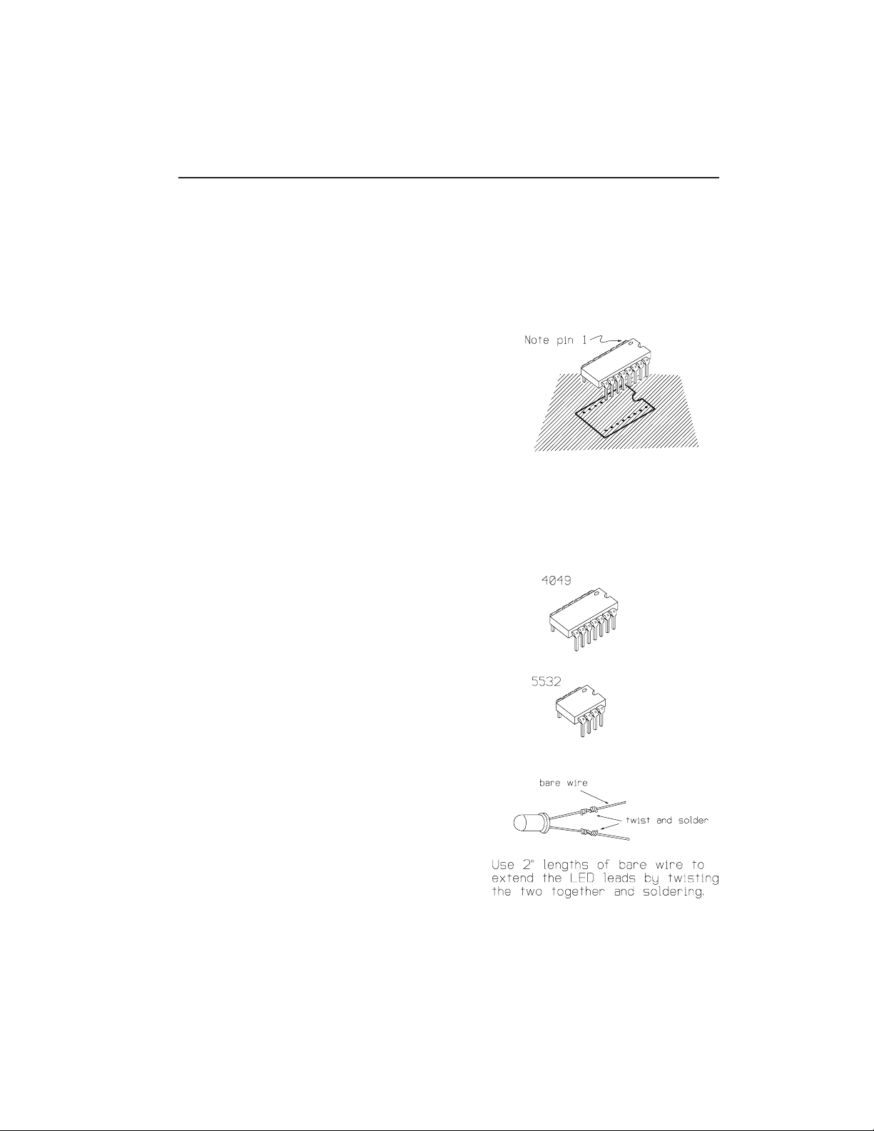
ICs are polarized in one or both of two ways; A
dot formed into the case of the IC corresponding
to pin 1 or a semicircular notch that indicates
the end of the package with pin 1. Take care that
this polarizing indicator corresponds to the
similar indicator on the circuit board graphics.
The pins of the ICs may be splayed somewhat and
not match the holes in the circuit board exactly.
Carefully re-form the leads if necessary
so that they are at right angles to the part.
Solder each IC in place as it is installed by
initially soldering two pins in diagonal corners
of the pattern. Make sure that the part is seated
firmly against the pc board by pressing it down
while remelting the solder joint at first one
corner, then the other. Finally, solder the
remaining connections.
DESIGNATION PART NO. DESCRIPTION
( ) IC1 4049 Hex inverting buffer
( ) IC2 5532 Dual low noise op amp
( ) IC3 5532 “
( ) IC4 5532 “
LEDs
When the TubeHead is installed in its case, the
three LEDs will engage the holes in the front
panel and be supported by their leads. Using six
2" lengths of the bare wire, extend the leads of
the LEDs as shown.
TubeHead 9
Page 10
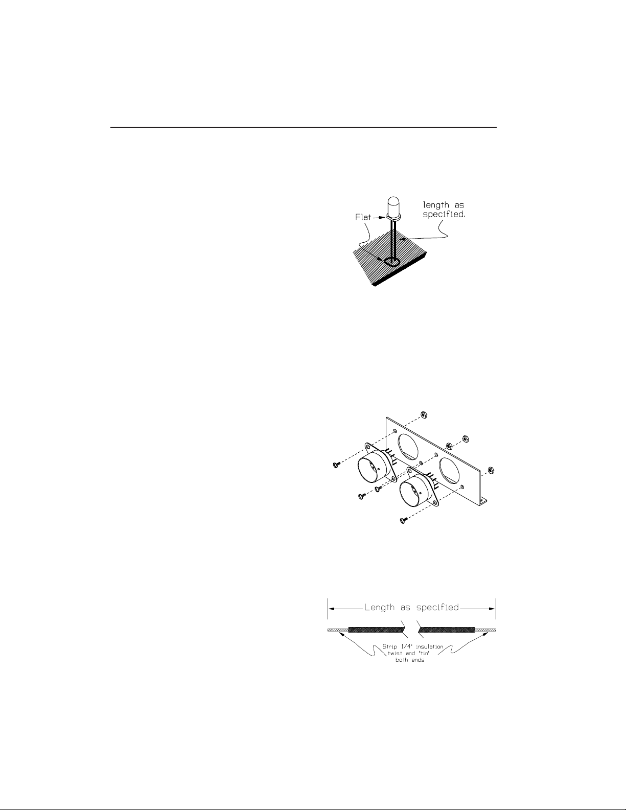
Note that the LEDs are polarized by the flat in
the collar at the base of part. When properly
installed, this flat will align with the
corresponding flat in the LED symbol printed on
the circuit board.
Push the two leads through the holes provided in
the circuit board and space the LED above the
board by the distance given in the step. Solder
both leads and check the spacing from the board to
the LED before trimming the leads off flush with
the solder joint.
DESIGNATION SPACING
( ) D3 1-1/4"
( ) D9 1-1/8"
( ) D10 1"
TUBE SOCKETS
( ) Attach the tube sockets to the aluminum
mounting bracket with four 4-40 X 1/4"
machine screws and four 4-40 nuts as shown in
the illustration. Notice that the sockets
mount from the “front” side (the mounting tab
that will attach the bracket to the circuit
board bends toward the “back”). Also note
that the sockets are polarized by the open
space between lugs 1 and 9 and that this
space should be to the left when the bracket
is viewed from the rear with the mounting
tab down (see fig 2). When you’re satisfied
that the sockets are properly oriented, fully
tighten the hardware. The bracket will attach
to the circuit board later.
Pieces of the single stranded insulated wire
provided with the kit are used to make connections
to tube’s filaments
( ) Cut two 3-1/4" lengths of the #22 insulated
wire and prepare both ends of both pieces by
stripping off 1/4" of insulation. Twist the
exposed wire strands together and “tin” them
by melting a little solder into the strands.
10 TubeHead
Page 11

( ) Form the two wires from the above step into a
“twisted pair” and solder one end of the pair
to lug #4 and lug #5 of the socket V2 (see
fig 3). On the other end of this pair,
connect the wires to lug #4 and lug #5 of V1
but DO NOT SOLDER these two connections yet.
The filament wires are interchangeable;
either can attach to either lug.
( ) In a similar manner, form a 6-1/2" twisted
pair and connect one end to lugs #4 and #5 of
the socket for V1. Solder the two wires
connected to each of these lugs. The free
end of this pair will attach to circuit board
points in later steps.
Now we’ll solder lengths of the bare wire to the
tube socket lugs. In later steps these wires will
have insulation slipped over them and then connect
to the circuit board.
( ) Cut twelve (12) 1-3/4" lengths of bare wire
and solder one piece to each of the tube
socket lugs 1, 2, 3, 6, 7 and 8. Notice that
there will be no wire connected to lug 9 of
either socket.
The sockets and bracket can be temporarily
attached to the circuit board. This is the time to
connect the bare wires from the tube sockets to
the appropriate circuit board holes. These
connections are made on a “one-to-one” basis with
the wire coming from lug #1 of the tube to the
hole marked #1 on the circuit board graphic for
that tube. With the exception of lug #8, the
wires will each have a length of insulated
sleeving slid over them. Cut the length of
sleeving as specified in the step, slide it over
the wire and then push the wire through the
appropriate hole in the circuit board.
TubeHead 11
Page 12

The sleeving lengths are identical for each tube.
Do not solder any of these connections yet.
WIRE NUMBER SLEEVE LENGTH
( ) 1 7/8"
( ) 2 1"
( ) 3 1"
( ) 6 1/2"
( ) 7 3/8"
( ) Temporarily attach the tube bracket to the
circuit board using two 4-40 X 1/2" machine
screws and two #4 machine nuts as shown in
fig 2. When the completed circuit board is
mounted in the case, this same hardware and
spacers will be used so do not fully tighten
these screws yet.
( ) Verify that the wires from the tube
properly engage the holes in the circuit
board and solder all twelve connections.
There will be a good bit of excess wire on
each connection which should be cut off flush
with the solder joint as the joint is
soldered.
( ) Connect the free end of the twisted pair
coming from lugs #4 and #5 of V1 to the two
holes designated “12VAC” on the circuit
board. The wires are interchangeable.
Solder both connections and clip any excess
wire off flush with the joint.
FLYING WIRES
We’re now ready to begin soldering lengths of wire
to the lettered points on the circuit board which
in later steps will be connected to front panel
controls, jacks and the power switch.
( ) Cut a 6" length of single stranded wire and
prepare the ends by stripping 1/4" of
insulation and twisting and tinning the
exposed wire strands. Push one end of this
wire through the circuit board hole marked
“A” and solder in place.
12 TubeHead
Page 13
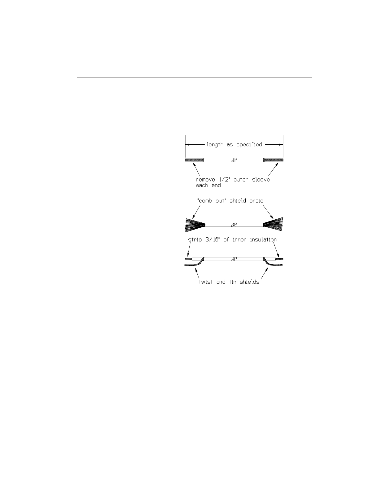
SHIELDED CABLE
RG-174/U coaxial cable will be used to make
shielded connections between the circuit board and
Jacks and Potentiometers. Each of these pieces of
co-ax should be prepared in the same way:
Cut a section of co-ax to the
length specified and strip 1/2"
of the outer insulation at each
end to expose the braided shield
beneath it.
Unbraid the shield by “combing”
it with the dull edge of a knife
blade or a ball-point pen. This
will expose the separately
insulated inner
conductor.
On each end, pull the strands
of shield to one side and twist
them together. Tin these pigtails
by melting a small amount of
solder into them.
On each end, strip about 3/16" of
the insulation from the inner
conductor and twist and tin the
exposed strands.
Using the specified lengths of co-ax prepared as
above, solder the inner conductor and shield to
the circuit board points listed in the following
steps (see fig 4).
PC POINT LENGTH
( ) “B” (center) 4-1/2"
( ) “C” (shield)
( ) “I” (center) 4-3/4"
( ) “J” (shield)
( ) “F” (center) 9-3/4"
( ) “H” (shield)
( ) “M” (center) 9-1/2"
( ) “N” (shield)
( ) “2” (center) 7-1/4"
( ) “SG” (shield)
TubeHead 13
Page 14
For the following lengths of co-ax the shield makes
no connection to the circuit board. Prepare the
lengths as above, except that the shield will be
clipped off even with the outer insulation AT THE
END THAT CONNECTS TO THE CIRCUIT BOARD ONLY.
PC POINT LENGTH
( ) “1” (center) 4-3/4"
( ) “3” (center) 4-1/4"
( ) “4” (center) 5-3/4"
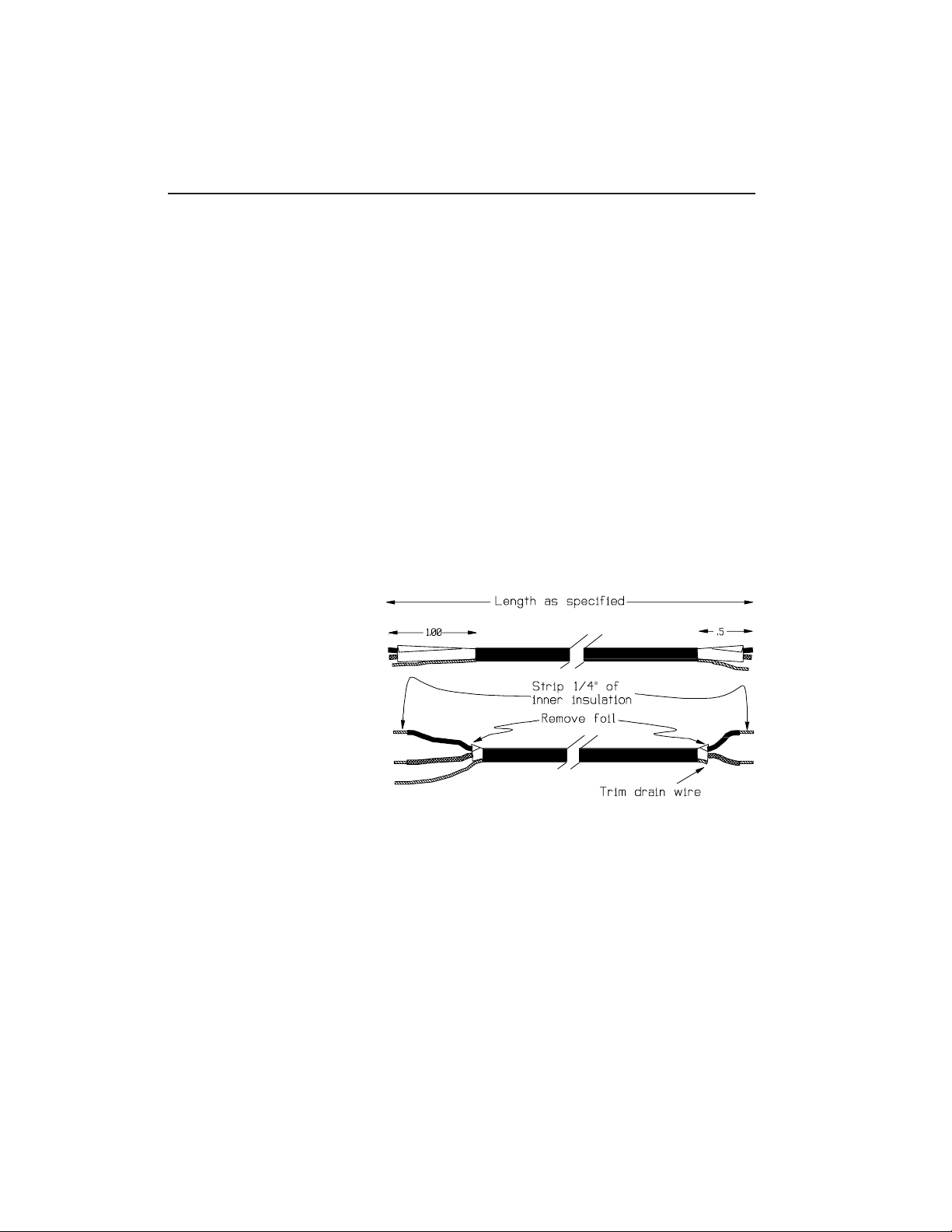
TWIN-AXIAL CABLE
Belden 9501 twin-ax will be used to make shielded
connections between the circuit board and the
Blend Pots. Make two cable sections by cutting
the length supplied into two equal lengths.
Prepare the ends of the two pieces as follows:
On one end of each cable,
remove 1/2" of the outer
insulating sleeve. Cut off the
exposed foil layer flush with
the outer insulation and cut
the uninsulated drain. Remove
1/4" of insulation from both
the red and black leads and
twist and tin the wires. Be
careful not to pull the wires
out of the cable when stripping
the ends.
On the other end of each cable,
strip 1" of the outer insulation,
remove the foil and remove 1/4" of
insulation from the red and black
leads before twisting and tinning.
On this end leave the drain wire
intact and tin its end.
Use the end with the drain wire cut off to make
these connections to the circuit board.
14 TubeHead
Page 15
CABLE 1 PC POINT
( ) red “E”
( ) black “D”
CABLE 2 PC POINT
( ) red “L”
( ) black “K”
We can now put the circuit board assembly aside
while we do some pre-wiring to the front panel
controls. This would be a good time to check your
work on the circuit board to this point. Make sure
polarized components are placed properly and be
critical of all your soldering joints.
PANEL CONTROLS
Because there will be limited space available in
the TubeHead case when the electronics are
installed, some point-to-point wiring will be done
on the pots before they’re installed in the case.
If you have the optional Rack Panel, it can be
used as a temporary fixture to hold the
potentiometers in place while soldering to them.
Using the flat washers and nuts supplied,
mount the 6 potentiometers to the rear of the
panel as shown in Fig 4. Note the orientation of
the panel (face down) and the pot’s solder lugs.
Hand-tighten the nuts so they will be easy to
remove when the pots are moved to the inside of
the case.
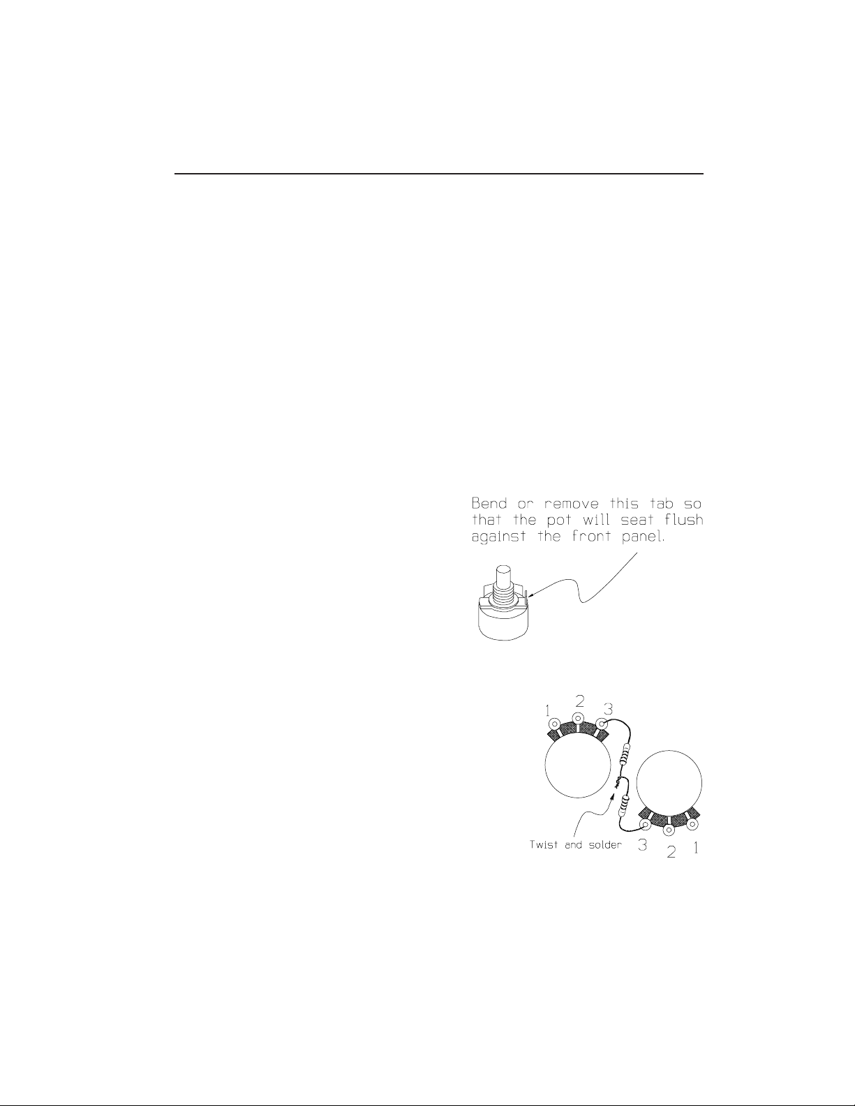
Four resistors (R7, R8, R35 and R36) mount on the
lugs of the pots.
( ) Locate the four 220 ohm (red-red-brown)
resistors and prepare them for mounting by
cutting their leads off to a length of 3/8".
Solder one end of each resistor to lug #3 of
potentiometers R15, R43, R18 and R46 as shown
in the illustration and fig 4.
( ) Twist the free leads of R7 and R35 together and solder.
( ) Twist the free leads of R8 and R36 together and solder.
TubeHead 15
Page 16

( ) Prepare a 3-1/4" length of the single
stranded insulated wire by stripping 1/4" of
insulation from both ends and tinning the
wire strands. Form a hook in one end of the
wire and slip it over the junction of R7 and
R35 from the above step. Crimp the hook
tightly over the resistor leads and remelt
the solder on the wires. Do not add more
solder to the joint unless absolutely
necessary.
( ) Connect the free end of the wire from above
to lug #2 of R20. Crimp the tinned end of
the wire over the lug to make a mechanical
connection but DO NOT SOLDER this connection.
( ) In the same manner as the above steps, use a
3-1/4" length of wire to make the connection
from the junction of R8 and R35 to lug #2 of
R48. DO NOT SOLDER THE connection at lug #2.
( ) Use a 2-1/2" length of wire to make the
connection between Lug #2 of R20 and Lug #2
of R48. DO NOT SOLDER either of these
connections.
( ) Prepare a 6" length of wire and connect one
end to lug #2 of R48. DO NOT SOLDER this
connection. The free end of this wire will
be connected in later steps.
Now we’re ready to begin connecting the ends of
co-ax and twin-ax cables originating at the
circuit board to the panel controls. In the
following steps individual solder lugs are
identified by part number and lug number. For
example, R15-1 means the lug labeled “1” of the
Potentiometer R15.
These connections should all be soldered as they
are made. Each step is followed by an instruction
such as (S2), which means that at that point there
will be two wires on the lug in question. If
there are not the number of wires specified at the
lug when you get ready to solder, recheck to see
what has gone wrong.
16 TubeHead
Page 17
These connections use the co-ax.
PC BOARD ORIGIN TO
( ) “B” (center) R15-2 (S1)
( ) “C” (shield) R15-1 (S1)
( ) “I” (center) R43-2 (S1)
( ) “J” (shield) R43-1 (S1)
( ) “F” (center) R18-2 (S1)
( ) “H” (shield) R18-1 (S1)
( ) “M” (center) R46-2 (S1)
( ) “N” (shield) R46-1 (S1)
These connection use the twin-ax.
( ) “D” (black) R20-1 (S1)
( ) “E” (red) R20-3 (S1)
( ) (drain) R20-2 (S3)
( ) “K” (black) R48-1 (S1)
( ) “L” (red) R48-3 (S1)
( ) (drain) R48-2 (S4)
We’re just about ready to start moving things into
the case, but first we’ll do a little prep work
involving the case bottom.
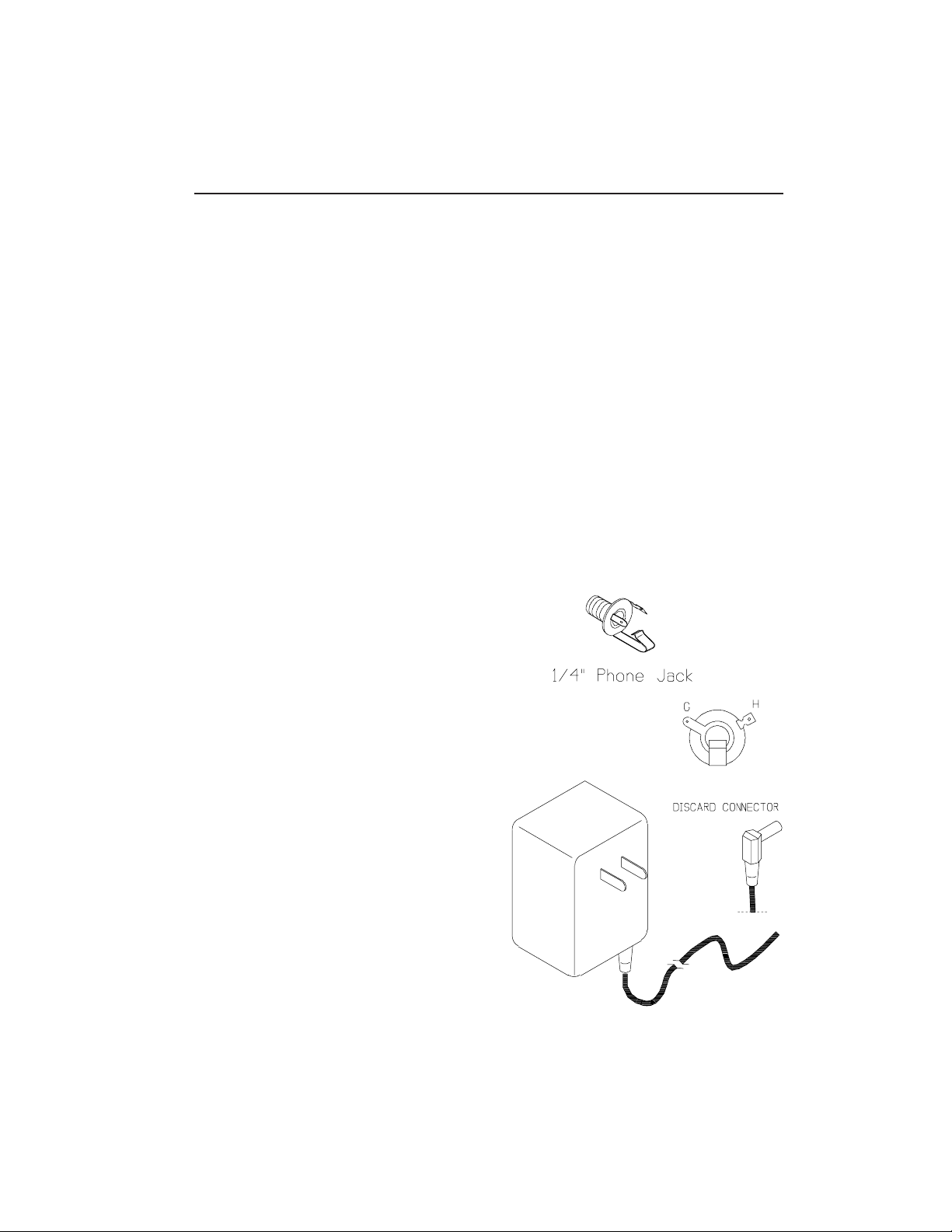
( ) Locate the four 1/4" Phone jacks and mount
them to the rear apron of the case using the
nuts and washers supplied with them (see
fig 5.) Orient the jacks so that their
solder lugs are easily accessible from the
open top of the case as shown in fig 4 before
fully tightening the hardware.
Locate the Wall Mount
Transformer (PWR1). If this
part has a connector
on the end of its cable,
remove and discard it as
shown.
( ) Install the rubber grommet in the power
supply cord hole as shown in Fig 5.
A pen point or small screwdriver may
be helpful in deforming the grommet
into the hole.
TubeHead 17
Page 18
( ) Pass the Transformer cord through the grommet
from the outside of the case and put a knot
in the cord 7" from the end. Separate the
two wires from the loose end back to the
knot.
( ) Cut one of the two wires from the transformer
to a length of 2" from the knot. Strip 3/16"
of insulation from ends of both wires and
twist and tin the exposed wire strands.
We can now begin installing the electronics in the
case. Carefully remove the assembly of pots and
fixed resistors from their temporary position on
the rack panel.
( ) Attach the Case to the Front Panel by passing
the shafts of the six potentiometers through
the matching holes in both parts and secure
them with one of the washers and the nut
provided with each pot (see fig 6.) Some
adjustment of the relative position of Case
and Panel will be necessary in later steps so
only finger-tighten the hardware at this
time. The TubeHead circuit board may be laid
in the case during this step, but do not use
any hardware to mount it yet.
( ) Connect the shorter wire of the Transformer
to circuit board point “G” and solder.
The Tubes fit tightly in their sockets. It will
be easier to insert them now than when the circuit
board is completely installed. Be careful of
orientation and cover the tubes with their shields
to prevent damage during final assembly.
While placing the circuit board in its final
position, also align the three LEDs so that they
engage the holes provided for them in the Case and
Panel. Adjust the relative positions of these
parts as necessary.
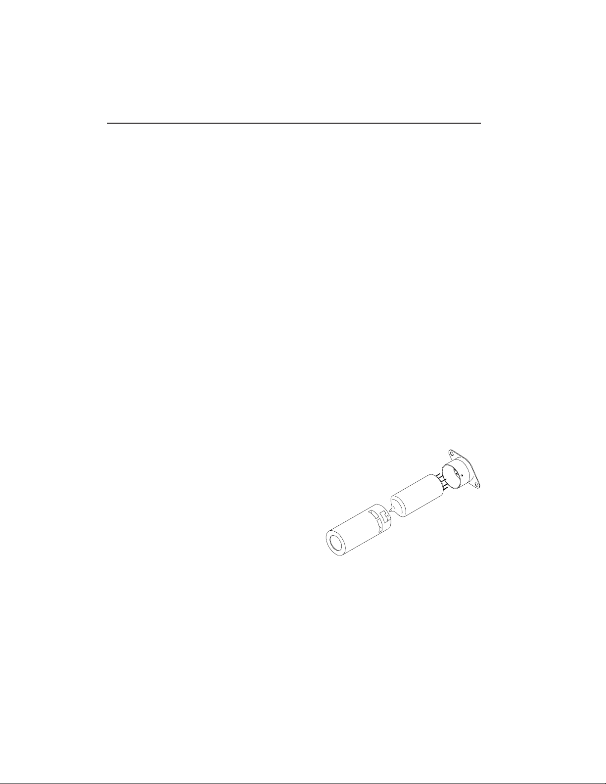
( ) Mount the TubeHead circuit board and Tube
Mounting Bracket to the case bottom using
four 4-40 X 1/2" machine screws, four #4 X
3/16" spacers and four #4 nuts as shown in
18 TubeHead
Page 19

fig 6. Two of the screws and nuts required
in this step are presently being used to
secure the Tube Mounting Bracket. The two
screws and spacers that do not mount the
bracket should be installed first because
their position toward the center of the board
will make them difficult to access later.
( ) Install the Power Switch (S1) in the location
shown in fig 5 by passing its shaft through
the matching holes in Case and Panel and
securing it with the nut provided. Now that
the case and Panel are fully aligned, make
any adjustment in the pot locations to center
them in the panel graphics and fully tighten
all of the panel hardware.
( ) Connect the free wire from the Transformer to
lug #1 of the Power Switch and solder.
( ) Connect the free end of the wire originating
at circuit board point “A” to lug #2 of the
Power Switch and solder.
( ) Prepare three 2" lengths of insulated wire
and use them to connect together the “G” lugs
of Phone Jacks J1-J4 as shown in fig 4. DO
NOT SOLDER these connections.
( ) Connect the free end of the wire originating
at lug #2 of R48 to lug “G” of J2. DO NOT
SOLDER.
In the final wiring steps the lengths of co-ax
originating at the circuit board will be connected
to the “G” and “H” lugs of the Phone Jacks.
PC POINT ORIGIN DESTINATION
( ) “1” (center) J1-H (S1)
( ) (shield) J1-G (S3)
( ) “2” (center) J2-H (S1)
( ) (shield) J2-G (S3)
( ) “3” (center) J3-H (S1)
( ) (shield) J3-G (S2)
( ) “4” (center) J4-H (S1)
( ) (shield) J4-G (S3)
TubeHead 19
Page 20

THIS COMPLETES THE ELECTRONIC ASSEMBLY OF THE TubeHead.
Before plugging the unit in and testing it, take a break
then come back and check your work completely.
TESTING IT
After rechecking your work, it’s time for the all important
smoke test. If anything unfortunate is going to happen,
this is the most likely time.
Plug the wall-mount transformer into a 120VAC outlet and
toggle the TubeHead to “ON.” The LED to the right of the
Power Switch should light and if it doesn’t, you should
immediately unplug the unit from the wall and find out why.
The problem could be nothing more than a dead wall outlet.
improperly placed components or solder bridges on the
circuit board may be the cause. Check the orientation of
the Integrated Circuits.
When the LED lights. Let the unit idle for a few minutes
while you check for parts that may be getting hot (other
than the tube, of course) or any unusual smell, smoke, etc.
Observe the tube filaments to make sure they’re glowing - if
not, check solder connection on the tube socket
and the twisted pair that connects the filament circuit to
the power supply.
If nothing seems out of place after a few minutes, plug a
low impedance, line level source in the Channel 1 Input (J1)
and the corresponding output (J2) to an amplifier. Set the
Channel 1 DRIVE, BLEND and OUTPUT controls to midrange and
confirm that the signals flows through the unit. Change the
settings of the controls and observe that each effects the
sound. Note that at some point in the rotation of the DRIVE
control the clip 1 LED comes on.
Disconnect the source and amp from Channel 1 and connect it
to Channel 2. Confirm that this Channel behaves the same
way Channel 1 did.
20 TubeHead
Page 21

() When you’re satisfied that
everything is working properly,
complete assembly by installing
the Case Top as shown in fig 6.
Four #4 self-tap screws secure
the front edge and side panels
of the top. The “L” bracket that
fastens fastens the rear edge of
the top is attached to the rear
apron of the Case Bottom using a
#4 X 1/4" Machine Screw and #4 Nut.
USING THE TUBEHEAD
Each channel has three controls. The DRIVE control sets how
hard the tube is driven and consequently how much it
squeezes the signal. The circuitry is arranged so that with
DRIVE set to minimum, the tube begins its non-linear
response at about 0dBm referenced to 600 ohms. With DRIVE
at maximum, non-linearity onset occurs at about 50 mV.
input.
The BLEND control sets the relative amounts of Clean and
Tube sound in the output. With the control fully CCW (the
“pre” setting) only the clean signal appears in the output.
Turning the control fully CW (to the “post” setting)
makes the output consist only of tube sound. You may find
that you always work with this control set all the way to
“post” and adjust the coloration of the signal with the
DRIVE control, but it’s also handy to be able to turn down
the heat by mixing in a little dry signal.
The final control for each channel is OUTPUT level. After
setting the coloration of the signal using the DRIVE and
BLEND controls, set output LEVEL as needed for best balance
and lowest overall noise in the signal path.
A few words about the CLIP LEDs is in order. These
indicators light when the first OpAmp gain stage is
clipping, they are not meant to indicate distortion in the
tube. If the CLIP indicator for a channel comes on, you
will want to reduce the DRIVE until it goes off.
Overloading the tube produces the effect we’re after,
overdriving the OpAmps does not.
TubeHead 21
Page 22
Nominal input impedance of the TubeHead is about 20k ohms,
consistent with most audio gear like Synths, Effects
Processors, Mixers, EQs and so on. 20k is a little low for
a proper match with high impedance sources like guitar
pickups, but a few minor changes will take care of the
incompatibility. If you want to use the TubeHead as an
instrument pickup preamp, remove R26 and C14 entirely and
change R21 to a value of 680k ohms and R12 to a value of
100k ohms.
The TubeHead is an ideal companion for the PAiA Phantom
Power Preamp, adding warmth and personality to even high-end
condenser microphones. Oh yeah, and CDs. Did we mention
that the TubeHead makes them sound almost musical?
Well, you probably get the idea - anytime you want to add a
little something extra to that sound your working ith,
reach for your TubeHead.
22 TubeHead
Page 23

WHY TUBES SOUND SO GOOD
All amplifiers distort if you drive them hard enough, but
tubes and transistors distort differently. Engineers use
transfer curves to show the relationship of an amplifiers
output signal to its input. In the figures below the
input (entering from the bottom) “reflects” off the curve to
produce the output at the right.
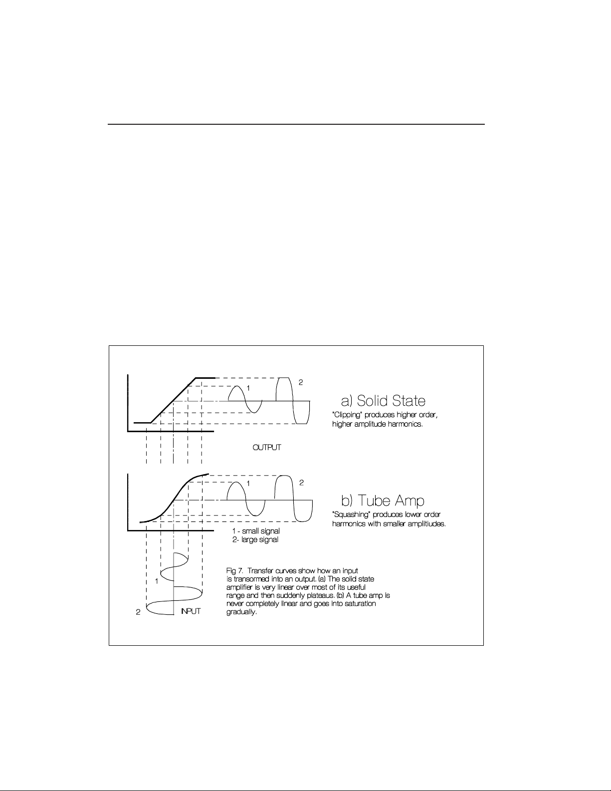
Fig 7a, the transfer curve of a typical transistor amp,
shows that everything is linear until you suddenly run out
of headroom, at which point the signal clips. This drastic
clipping produces high-amplitude odd order harmonics which
are not particularly pleasing.
Fig 7b, a tube transfer curve, is linear only for very small
signals. The curve’s ends, which bend over gradually rather
than suddenly reaching a plateau, “squash” the signal at
higher levels rather than clipping it. This produces a more
rounded waveform that’s responsible for much of the
characteristic “tube Sound”
The TubeHead exaggerates the naturally soft curve common to
all tubes, resulting in almost a caricature of a tube amp.
Running the 12AX7 at low supply voltages and plate currents
puts the tube way down in a nonlinear region of its
operating range. This region is generally considered so
uninteresting that it doesn’t even show up in reference
books, but it’s great for tube-sound amplifiers.
The two cascaded tube stages complement one another; one
rounds the upper end of the transfer curve while the other
rounds the bottom, providing a symmetrical transfer
curve. Trimmers on the circuit board are used to set
this symmetry.
TubeHead 23
Page 24

DESIGN ANALYSIS
Power from the 12 VAC transformer is
positive half-wave rectified by D1 and
filtered by C1, C2 and R1 for a +15V
supply rail. A -15V supply is provided by
D2, C3, C4 and R3.
Most tube circuits operate at high
voltages, frequently hundreds of Volts,
and components for these voltages can
be
expensive and difficult to find. But we get
a little break here because the trick that
we use to make a tube really SOUND
LIKE a tube is to “starve” it with low plate
voltage.
Even the 45 Volts used in the TubeHead
is higher than you typically find in solid
state circuitry. Rather than use an exotic
multiwinding power transformer, the
tube’s plate supply is produced by a
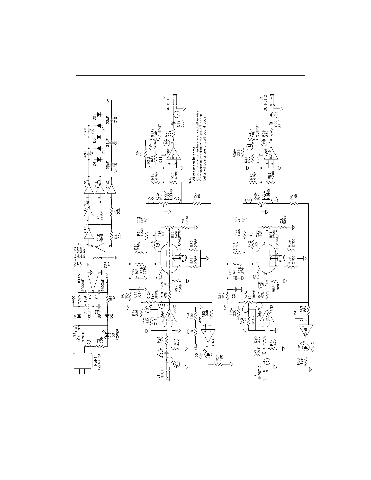
voltage multiplier. As shown in the
schematic,
fig 8; C7, R4 and R5 together with three of
the six inverters in IC1 form a 60 kHz., 15V
p-p square wave oscillator. The remaining three buffers in IC1 are wired in
parallel to provide greater output current
to drive the network of diodes (D4-D8)
and
capacitors (C5, C6, C8-C10) that multiply
the 15V square wave up to 45VDC.
You will quickly notice that the two
channel Tubehead clearly consists of two
identical preamp/tube/final amp sections.
We’ll talk about the channel built around
V1 and IC2, but everything said about this
section applies to the V2, IC3 section as
well.
The signal path begins with an adjustable gain stage built around one of the
two low noise OpAmps in a 5532 (IC2:A).
Input signals are capacitively coupled by
C17 and appear across R26. When the
24 TubeHead
DRIVE control R15 is fully CCW The
ratio of R12 to R21 sets the minimum voltage
gain to 1/2 (a 2:1 attenuation). At the CW end,
the ratio of R15 to R7 (more or less) sets the
maximum voltage gain to 25. Capacitor C14
rolls off the high frequency response at a
corner frequency of about 30 kHz. An OpAmp
wired as a comparator (IC4:A) turns on LED
D9 when the output of the gain stage approaches its clipping point.
The output of the gain stage is coupled by
R19 and C18 to R27, the grid resistor of the
first tube stage. Two tube stages are used to
optimize the symmetry of the output waveform.
A single tube stage would compress the tops
of waveforms, but leave the bottoms unchanged. With two stages, the first can
squeeze the top of the signal, invert it and
send it to the second stage to squeeze what
was
originally the bottom.
Both tube stages are contained within V2, a
12AX7 Dual Triode. The output of the first tube
stage appears across the plate load resistor
R10 and is coupled by R14 and C15 to the
SYMMETRY trimmer R23, which sets the
amount of signal applied to the grid of the
second stage. The output f the second stage
appears across plate load resistor R11.
A final output buffer stage built around OpAmp
IC2:B converts the relatively high impedance
output of the tubes to a more reasonable
lower impedance consistent with contemporary audio processing gear. It’s operation is
very similar to that of the circuitry around IC2:A.
IC2:B also provides for mixing the dry signal
(pre-tube) with post-tube processed signal
using the BLEND pot R20. At the CW end of
the rotation of the BLEND pot, the final
amplifier is fed exclusively with the output of
the tube. At the CCW end, it’s fed by the
buffered input signal from the first gain stage.
At intermediate settings of R20 a mix of the dry
signal and the tube output drive the final
buffer. The relative values of R37 and R61
compensate for the addition gain of the tubes
so that overall level is fairly constant as
BLEND is varied from “pre” to “post”.
Page 25
TubeHead 25
Page 26

TubeHead
Packing List
2 .01 Ceramic Disk Capacitor
1 .05 “ “ “
2 20pF “ “ “
1 220pF “ “ “
2 5pF “ “ “
2 100uF / 25V Electrolytic Capacitor
2 1000 / 16V “ “
8 1uF/ 50V “ “
2 2.2uF/25V “ “
7 33uF / 25V “ “
5 1N4148 Signal Diodes
2 1N4001 Power Diodes
3 Red LED
1 4049 CMOS Hex Inverting Buffer
3 5532 Dual Low-Noise OpAmp
4 1/4" O.C. Phone jack
2 100k Horizontal Trimmer Pot
6 10k Panel Mount Potentiometer
4 100 ohm all fixed resistors are
4 100k 1/4W, 5%, values in ohms
5 10k
2 150k
11k
4 220
2 22k
4 2700
4 270k
3 330
2 33k
4 470k
6 47k
2 8200
4 82k
1 SPST Toggle Switch
1 12V 500mA AC Transformer
2 12AX7
2 9 Pin Tube Sockets
6 Set Screw Knobs
1 9305 Circuit Board
1 Tube Mounting Bracket
2 4-40 X 1/2" Machine Screws
4 4-40 X 1/4" Machine Screws
6 #4 machine nuts
48" #22 stranded wire
52" RG-174/U co-ax
14" Twin-axial cable
42" Bare Wire
18" Small Insulated Sleeving
TubeHead Rack Case
Packing List
1 Rack panel
1 case top
1 case bottom
4 3/16" spacers
2 4-40 X 1/2" Machine Screws
2 4-40 X 1/4" Machine Screws
3 #4 X 1/4" machine nuts
1 “L” Bracket
4 #4 X 1/4" Self Tap screws
1 1/4" Rubber Grommet
26 TubeHead
Page 27

NOTES
TubeHead 27
Page 28

28 TubeHead
PAiA Electronics, Inc.
3200 Teakwood Ln.
Edmond, OK 73013
fax (405) 340-6378
phn (405) 340-6300
 Loading...