

U5136G
Intelligent Linking Batteries
User Guide

PAG Ltd.
565 Kingston Road
London SW20 8SA
United Kingdom
E: sales@paguk.com
T: +44 (0)20 8543 3131
www.paguk.com
Disclaimer
The information contained in this document is correct at the time
of publication. PAG Ltd. reserves the right to change
specifications or product details without notification. Changes to
product details will be incorporated in the next version of the
document. PAG updates documents on a regular basis.
Trademarks
All PAG registered trademarks are the property of PAG Ltd.
All third party trademarks are acknowledged as such.
Patents Apply: paguk.com/patents
Copyright © 2020 PAG Ltd. All rights reserved

Contents
Section Page
1 Introduction 4
2 Specification 5
3 Charging 6
4 Discharging 9
5 Storage 11
A User Guide for Mini PAGlink Gold Mount
Intelligent Linking Batteries.
Please read the important safety information and
instructions before using your battery.
6 Battery Linking Features 12
7 Run-Time, Capacity & Data 14
8 Battery Outputs 16
9 Battery Protection Features 17
10 Safety Information 18
11 Servicing 19
12 Recycling 20
13 Guarantee 21
14 Air Transport 22
3

1. Introduction
1.1 Models covered by these instructions:
Model No. Name Capacity Mount
7141 MPL50 50Wh Gold Mount
7241 MPL99 99Wh Gold Mount
1.2 Mini PAGlink Gold Mount batteries are designed to be compatible
with the Gold Mount battery plate (Anton/Bauer).
1.3 They feature all the benefits of PAGlink intelligent linking technology
combined with a reduced form factor and increased durability.
1.4 They are available in 2 flight-friendly capacities: 50Wh and 99Wh.
Batteries can be linked to create greater capacities on location,
allowing you to travel with all the power you need.
1.5 The unique PAGlink technology allows up to 8 batteries to be linked
for charge or discharge, regardless of their rated capacity or their
state-of-charge. Both the MPL50G and MPL99G can be linked with
Gold Mount PL94 and PL150 batteries, for charge or discharge.
1.6 The batteries can be used as a single power source for smaller
camcorders and their accessories. In this application they replace a
multitude of incompatible batteries. However, they can also be used
to power larger cameras and other production equipment, such as
monitors.
Display
Display
Button
Battery Lock
& Release
Button
PAGlink
Contacts
1/4” Bush
D-Tap Output
MPL50G Front
1/4” Bush
USB (2A)
Output
Unit
4

USB (2A)
Output
Unit
Output Unit
Release Slider
MPL50G Back
Main
Battery
Contacts
1. Introduction
1.7 The batteries feature built-in D-Tap outputs (12V) and a replaceable
USB output unit (5V 2A) that can be swapped for Lemo, Hirose or DTap output units, already available for the Gold Mount PowerHub.
1.8 These smaller, lighter batteries allow you to control the capacity and
weight of your power source to suit the application: 1 battery is ideal
for handheld applications, 2 or more linked batteries provide longer
run-time or an increased current draw of up to 12A, ideal for
powering multiple accessories. Current is delivered using superior,
high-current pin contacts.
1.9 PAGlink allows seamless hot-swapping for continuous power, or the
ability to add another battery just to keep shooting, which means no
more time-wasting camera reboots.
1.10 Simultaneous discharge from linked batteries means no dead weight
on your camera. Sharing the current load extends overall battery life
to provide a better return on investment. Both the MPL50 and MPL99
batteries are guaranteed for 2 years.
1.11 The PAGlink technology will automatically select the most suitable
batteries for discharge, according to their charge status. Batteries do
not discharge into each other. The system ensures that the maximum
linked output is kept to a safe level.
1.12 The intelligent PAGlink batteries manage their own charging safely
and efficiently, and can be charged, whilst linked, using other
5

1. Introduction
reputable manufacturer’s Li-Ion chargers. They are compatible with
PAGlink and Anton/Bauer chargers for maximum versatility and
economic integration.
1.13 Batteries in any state of charge can be linked for charging, in
multiples of 8 or fewer. During charging, the least-charged batteries
are given priority. When the batteries reach a similar state of charge,
they will charge simultaneously. The charge status of each battery is
shown on its individual display.
1.14 The batteries feature an ergonomic design and a ‘soft-touch’ coated
protective band for safer handling and increased durability.
1.15 1/4” bush inserts have been incorporated to enable the mounting
of accessories to individual or linked batteries.
1.16 The battery display provides remaining run-time, on-load, in 1 minute
increments, for the total of all linked batteries. It shows remaining
capacity for each individual battery in 1% increments, at any time.
It also provides useful data, such as the number of charge/discharge
cycles, to assist with battery management.
1.17 When linked, Mini PAGlink batteries form a network that allows them
to communicate with each other and report to the camera as one
battery.
1.18 They will automatically detect and adapt to the camera data
system that allows Anton Bauer Gold Mount batteries to provide
capacity information in the camera viewfinder/LCD.
1.19 The batteries feature a fully-serviceable, modular construction that
allows authorised replacement of the cell-pack whilst maintaining
conformity with UN standards and IATA air transport regulations.
1.20 The battery firmware can be updated easily by the customer, via
external contacts, using an update tool provided by PAG.
1.21 PAG’s patented intelligent battery linking technology remains far in
advance of any other camera battery system available today.
1.22 PAG Li-Ion batteries are tested by Intertek Group plc to UN 38.3
standard in compliance with IATA Air Transport regulations.
Patents Apply: paguk.com/patents
6

2. Specification
2.1 Cell Technology:
Premium-grade Lithium-Ion sealed rechargeable cylindrical cells.
2.2 Capacity:
Model 7141: 50 Watt-hours (nominal 3.5 Ampere-hours).
Model 7241: 99 Watt-hours (nominal 6.7 Ampere-hours).
2.3 Voltage:
14.8V nominal.
2.4 Output Current:
The rated maximum continuous output current for an individual 50Wh
battery is 8A, and for a 99Wh battery it is 10A. Two or more linked
batteries of any rated capacity, in a similar state of charge, will
deliver an increased continuous current of up to 12A.
2.5 Fixed D-Tap Outputs:
12V (unregulated), designed for powering camera accessories.
Model 7141 MPL50G features 1 built-in D-Tap output.
Model 7241 MPL99G features 2 built-in D-Tap outputs.
2.6 Removable USB Output:
Each battery incorporates 1 removable USB Output Unit, 5V regulated,
2A continuous, 3A peak. The unit can be removed and replaced with a
Hirose (4-pin), Lemo (2-pin), D-Tap or a 2.1mm DC output unit. These
are available individually from PAG or its resellers. They are the same
interchangeable output units available for the Gold Mount PAGlink
PowerHub Model 9712.
2.7 Temperature Range:
Charging:
0°C to +45°C Optimum +10 to +40°C
+32°F to +113°F Optimum +50°F to +104°F
Discharging:
-20°C to +50°C Optimum +10°C to +40°C
-4°F to +122°F Optimum +50°F to +104°F
Storage:
-10°C to +40°C Optimum 0°C to +20°C
+14°F to +104°F Optimum +32°F to +68°F
2.8 Overall Dimensions (L x W x H):
Model 7141 MPL50G: 109mm (4.3”) x 87mm (3.4”) x 43mm (1.7”)
Model 7241 MPL99G: 109mm (4.3”) x 87mm (3.4”) x 60mm (2.3”)
2.9 Weight:
Model 7141 MPL50G: 360g (12.7oz) approx.
Model 7241 MPL99G: 590g (21oz) approx.
7

3. Charging
3.1 IMPORTANT: READ THE CHARGER HANDBOOK BEFORE ATTEMPTING TO
CHARGE THE BATTERY.
3.2 NOTE: The battery is put into ‘ship mode’ prior to transit.
It can be activated by connecting it to a charger that is poweredup, or by linking it to a battery that is already active.
3.3 Mini PAGlink batteries can be charged individually or linked, regardless
of their capacity or state of charge. They can also be charged when
linked to PAGlink Gold Mount batteries Models PL94 (9306) and
PL150 (9313).
3.4 The least-charged batteries are given priority until all the batteries are
in a similar state-of-charge. They will then be fully-charged simultaneously. Up to 8 batteries can be linked for charging on each
position. The following PAGlink chargers can be used:
9707A PAGlink PL16 Charger 2-positions, 8 batteries on each
9711A PAGlink PL16+ Charger 4-positions, 4 batteries on each
9713 PAGlink Micro Charger 1-position, 8 batteries in total
Some Anton Bauer Gold Mount Li-Ion chargers may also be suitable.
The number of linked batteries that can be charged on each position
is dependent on the charger model and firmware version.
3.5 Charge Times: From fully-discharged to fully-charged:
Capacity PL16 Times Micro Charger Times
50Wh 01:15 02:00
100Wh 01:30 04:00
200Wh 03:00 08:00
300Wh 04:45 12:00
400Wh 06:00 16:00
600Wh 09:00 24:00
800Wh 12:00 -
1600Wh 24:00 -
3.6 Mini PAGlink batteries display their individual status during
charging on their built-in display.
3.7 The batteries incorporate a temperature sensor which will
inhibit charging if their temperature is below 0°C. See
Specification for the charging temperature range.
8

4. Discharging
4.1 Mini PAGlink batteries can be discharged individually or linked. They
can also be discharged linked to PAGlink Gold Mount batteries Models
9306 PL94T and 9313 PL150T. The batteries can be in any state of
charge. The maximum number of PAGlink batteries that may be linked
has been limited to 8. If more than 8 batteries are linked, the
management system will shut-down the supply, and no current will
flow.
4.2 Linking batteries for discharge provides a number of benefits:
The combined capacity extends the run-time of your camera set-up.
Two linked 50Wh batteries will provide 100Wh; a 50Wh and a 94Wh
battery linked will provide 144Wh; a 50Wh and a 150Wh battery will
provide 200Wh.
Where total continuous consumption is above 8A, two or more
batteries, of any rated capacity, should be linked. This will increase
the maximum continuous discharge current to 12A, provided the
batteries are in a similar state of charge. Sharing the current load
across multiple batteries prolongs individual battery life and provides
a better return on investment.
4.3 Linked batteries form a network which allows communication between
batteries, ensuring that a safe protocol is followed under all circumstances.
4.4 The PAGlink management system elects the battery with one or more
connected to its front contacts to be the ‘master’ and ensures that
this battery is always active (but not necessarily delivering current).
The system makes the most efficient use of the power available, and
prevents a transfer of charge between batteries. As discharge
progresses, batteries are electronically added to or subtracted from
the bus bar to deliver the current required. The linked batteries
discharge simultaneously rather than sequentially. Their individual
state of charge and the total run-time can be viewed via their
displays. As long as the ‘master’ remains connected, batteries may be
added or hot-swapped in order to achieve continuous running.
4.5 The batteries incorporate a precision, fixed, end-of-discharge cutoff,
set to 12.5V, as measured by the battery. This cutoff will only
operate if the battery capacity is less than 5%, eliminating unwanted
operation due to high current and low battery temperature.
4.6 The batteries incorporate a current limit of 8A for an individual
battery and 12A for linked batteries. Consumption above this for
more than 5 seconds will trigger the over-current protection, turning
the battery output off. It can be recovered by simply removing it
from the load and pressing the display button, provided the battery
still retains some charge.
4.7 The batteries may be discharged within the temperature range -20°C
to +50°C, but for optimum performance, +10°C to +40°C is
recommended. The operating time will be shorter in conditions of
low temperature, and discharging will be electronically inhibited if
the battery temperature is below -20°C.
9

4. Discharging
4.8 When the battery has been discharged at a high rate it will become
warm, and it is advisable to let it cool before charging.
4.9 When not in use, batteries should be kept in an unlinked state to
ensure a lower self-discharge rate.
10

5.1 For the short term, batteries can be left stacked on a charger until
required; the charger will keep them topped-up ready for use.
5.2 For long-term storage, batteries should be in a half-charged state
(between 20% and 80%), and not linked.
5.3 After a long period of inactivity, a Mini PAGlink battery will auto-
matically enter Ship Mode, which greatly reduces its rate of selfdischarge. It can be reactivated by connecting it to a charger that is
powered-up, or by linking it to a battery that is already active.
5.4 Batteries should be stored in a cool, dry place at a temperature
between 0°C and +20°C. Long-term storage outside of this temperature range may reduce the battery’s life. Maintenance charging is not
required during long term storage.
5.5 After storage it is advisable to fully-charge batteries before use.
5. Storage
11

6. Battery Linking Features
6.1 Linking Batteries:
UNLOCKED
LOCKED
PRESS
RELEASE
BUTTON
To link batteries, align the gold studs of one battery with the claws
on the front of another. Slide the battery across until you hear a click
and the locking indicator is visible on the front battery’s release
button.
12
To unlink batteries, hold down the front battery’s release button and
slide the battery to the left.

6. Battery Linking Features
6.2 Mini PAGlink batteries can be discharged and charged individually or
linked, combining their capacities. Two 50Wh batteries will provide
100Wh when linked, 3 will provide 150Wh, etc.
Mini PAGlink batteries can also be linked to PAGlink PL94 and PL150
batteries. A 50Wh MPL50G and a 94WhPL94 battery linked will
provide 144Wh; an MPL50G and a PL150 will provide 200Wh.
Batteries of any rated capacity, in any state of charge, can be linked
for charge or discharge.
Linking batteries increases the maximum continuous current draw
capability to 12A, provided the batteries linked are in a similar state
of charge. See Specification for the batteries’ individual current draw
capability.
The maximum number of PAGlink batteries that may be linked has
been limited to 8. If more than 8 batteries are linked, the management system will shut-down the supply, and no current will flow.
Linked batteries form a network which allows communication between
batteries, ensuring that a safe protocol is followed under all
circumstances. The PAGlink management system elects the battery
with one or more connected to its front contacts to be the ‘master’
and ensures that this battery is always active (but not necessarily
delivering current). The system makes the most efficient use of the
energy available, and prevents a transfer of charge between batteries.
As discharge progresses, batteries are electronically added to or
subtracted from the bus bar to deliver the current required.
DIGITAL BATTERY
COMMUNICATION
MASTER
BATTERY
OUTPUT
BUS BAR
The status of individual batteries and total run-time can be viewed
via the battery displays. As long as the ‘master’ remains connected,
batteries may be added to or removed from the stack (hot-swapped)
in order to achieve continuous running.
NOTE: When not in use, batteries should be kept in an unlinked
state to ensure a lower self-discharge rate.
13

7. Run-Time, Capacity & Data
7.1 The Battery Display:
The battery is able to display a numeric run-time prediction against
load, and charge status as a percentage.
When connected to a camera that is turned-on,
two presses of the battery’s display button will
show a predicted run-time against the given
load, expressed in hours and minutes. When
batteries are linked the run-time displayed
relates to the total for the connected
batteries.
A single button press of the display, off or
on-load, shows a percentage figure of
available capacity. When the batteries are
linked this figure still relates to the battery’s
individual capacity.
When individual battery capacity drops below
5% the display will indicate that the battery
should be charged, as shown.
When the battery is fully charged the display
will indicate 100%.
7.2 Display Data Output:
Data stored in the battery’s microprocessor can be revealed using the
battery display:
Press display button
x3 in 1 sec intervals &
hold for data mode
Release to see 1st
menu item: ‘Pd’
(voltage)
Press without holding
for 2nd menu item
Press twice
without holding
for 3rd menu item
Press & hold for
3 seconds to see
voltage reading
Press & hold for temperature in degrees
celsius
Press & hold for
number of charge/
discharge cycles
14

7. Run-Time, Capacity & Data
7.4 PAGlink Battery Reader
The PAGlink Battery Reader (Model 9647A) is an accessory that can be
used to display data stored in the battery’s microprocessor. When
connected to the battery contacts it will provide information that is
beneficial for managing your batteries:
Press x3without
holding for software
version
After selecting to view the software version number, the battery will
enter Ship Mode automatically. Ship Mode reduces battery selfdischarge and can be used when you are going to store or ship your
batteries. To exit Ship Mode, link the battery to another active battery
or connect it to a charger that is powered-up.
7.3 In-Viewfinder Battery Status
Battery status can be shown as a percentage of available capacity in
the viewfinder/LCD of cameras designed to accept this data. Different
data standards are used by camera and battery manufacturers. PAGlink
Gold Mount batteries automatically adjust the data output standard to
support the system that allows Anton Bauer batteries to display
capacity information in the viewfinder/LCD. When the batteries are
linked, the data displayed is for the combined capacity available.
Press & hold for
version number...
...which appears in
2 parts indicating
version 2.0
Reader Menu:
1. State of charge as a percentage
2. Available capacity in ampere-hours
3. Cell temperature in degrees Celsius
4. Number of charge/discharge cycles
5. Voltage
6. Full capacity in ampere-hours
7. Date of birth (manufacture)
8. Software version
9. Serial number
15

8. Battery Outputs
8.1 Mini PAGlink batteries feature built-in D-Tap outputs (unregulated)
designed for powering 12V camera accessories. They also incorporate
a USB output unit, regulated at 5V (2A), which is interchangeable
with other output unit types: Hirose (4-pin), Lemo (2-pin) & D-Tap.
REAR OF BATTERY
OUTPUT UNIT
SLIDE
LEFT
To remove the USB output unit, push the release slider on the rear of
the battery to the left. When the unit is protruding from the battery
case it can be pulled-out easily. To fit a different output unit type,
align the locator at the top of the output unit with locator in the
port, and push-in the unit until a click indicates that it is secured.
8.2 Output Units for Mini PAGlink batteries:
D-Tap
Model 9712D
Hirose (4-pin)
Model 9712H
Lemo (2-pin)
Model 9712L
USB (5V 2A)
Model 9712U
16

9.1 Over-charge Protection
Charging will be inhibited if the battery voltage exceeds a pre-set
level.
9.2 Over-discharge Protection
When the battery voltage reaches 12.5V, discharging is inhibited.
9.3 Over-current Protection
If a single 50Wh battery is subjected to a current greater than 8A
(10A for a 99Wh battery), but less than 15A, the output will be
turned off after 5 seconds. If the current is greater than 15A, the
output will be turned off immediately. In either case, the battery
display will be inoperative and there will be no voltage available at
the terminals. The battery can be reset by removing it from the load
and pressing the display button.
9.4 Thermal Protection
Software protection inhibits charging if the battery temperature is
below 0°C. Return the battery to the charger when the battery
temperature rises above 0°C.
Software protection inhibits discharging if the battery temperature
falls to -20°C, or if it rises to +70°C. The output can be restored
when the battery temperature becomes within the specified range
by pressing the display button.
A thermal fuse is incorporated within the battery construction as a
‘backstop’ protection device, and this cannot be reset. In the unlikely
event of this fuse operating, please contact PAG or your dealer.
9. Battery Protection Features
9.5 Construction
The battery cases consist of high-impact ABS injection mouldings,
designed to protect the cells from impact damage. The battery has
been drop-tested.
The circuits are coated, making them resistant to electrolyte and
ensuring the operation of the electronic safety systems in the event
of damage to the battery.
Internal wiring is rated for high current and high temperature, and is
double-insulated for added safety and protection.
17

10. Safety Information
10.1 PLEASE READ THESE IMPORTANT SAFETY INSTRUCTIONS BEFORE
USING THE BATTERY AND RETAIN THEM FOR FUTURE REFERENCE.
When used correctly, Lithium-Ion batteries are a rugged and safe
method of storing power. However, incorrect treatment of the battery
could present a hazard. In the interest of safety, and the protection
of our environment, please read and observe the following health and
safety information.
WARNING:
Do not drop, throw, puncture, crush or incinerate the battery. Severe
mechanical abuse of the battery could result in damage to the cells,
and short-circuit internal to the battery. Li-Ion cells can deliver
power at very high rates. Arcing, excessive heat and the liberation of
combustible gas could result, with the potential for personal injury
or ignition of adjacent flammable materials.
Do not short-circuit the battery.
Keep the battery away from fires, strong sunlight and excessively
hot environments.
Avoid getting the battery wet and do not use it if it has been
immersed in water.
Do not attempt to disassemble the battery. Refer faults to authorised
service personnel.
Do not continue to use the battery if there is any change in the
appearance of the casing.
CAUTION:
The battery electrolyte is an alkaline solution, which can cause
chemical burns to human tissue. Leakage can occur as a result of
severe damage to the battery. Wear protective gloves when handling
all contaminated materials. In the event of contact with the skin,
flood copiously with clean water. If significant amounts of electrolyte
are involved, or if any has touched the eyes, seek immediate medical
attention.
ELECTRIC SHOCK: This symbol appears where the information relates to the risk of electric shock.
WARNING: This symbol appears where the information
relates to an issue of personal safety.
18
11. Servicing
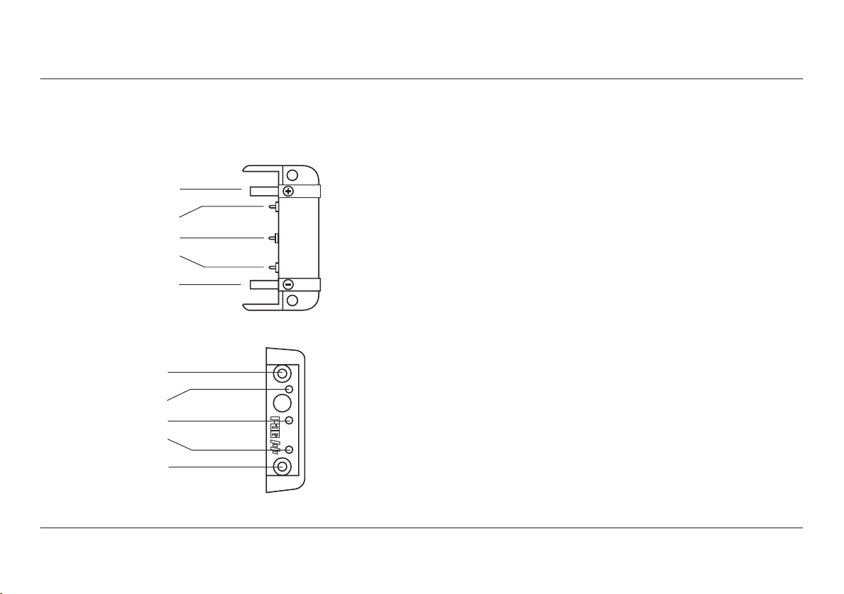
11.1 The following assemblies are separate to the battery case and can be
replaced by customers in the event of damage:
Front Contact Assembly:
Positive
Link Detect
PAGlink Comms
Reserved
Negative
Rear Contact Assembly:
Positive
Viewfinder Data
PAGlink Comms
Talk
Negative
Parts and instructions can be obtained from PAG Ltd. or an authorised
PAG service centre.
11.2 Customers should not attempt to open the battery case for repair or
any other purpose, unless authorised by PAG Ltd. Unauthorised
servicing invalidates the battery guarantee and its air safety status
(IATA).
If a fault develops, please contact a PAG service centre to receive a
fault diagnosis. Batteries that require further analysis must be
returned to your nearest PAG service centre. Li-Ion batteries are
classified as dangerous goods and cannot be returned without prior
contact. A consultation will be provided, followed by an estimate,
prior to any repair.
Authorised PAG Service Centres:
The Americas: PAG America (a division of Carr Distribution Group)
18 Center Street, Ramsey, NJ 07446, USA
Tel: +1 631 300 8215, Email: sales@pagamerica.com
Europe & Middle East: Aspectra B.V.
Spoorhaven 78, 2651 AV, Berkel en Rodenrijs, Netherlands
Tel: +31 (10) 5140680, Email: info@aspectra.nl
UK & RoW: PAG Ltd.
565 Kingston Road, Raynes Park, London SW20 8SA, UK
Tel: +44 (0)20 8543 3131, Email: support@paguk.com
19

12. Recycling
12.1 Do not dispose of batteries or cells in a charged condition.
Expired batteries should be disposed of in accordance with the
appropriate regulations or legislation.
PAG offers a recycling service for its expired batteries in the UK.
They can be returned to PAG Ltd. only by prior arrangement. They
must be in a discharged state, and clearly marked ”FOR RECYCLING”.
Please do not attempt to return Li-Ion batteries for recycling
without first contacting an authorised PAG Service Centre.
20

13. Guarantee
13.1 Notwithstanding any provision of any agreement the following guarantee
is exclusive: PAG Limited guarantees each Mini PAGlink MPL50G battery
it manufactures to be free of defects in material and workmanship, under
normal use and service, from the date of purchase, for the period
indicated below:
MPL50G Model 7141
MPL99G Model 7241
This guarantee extends only to the original purchaser. This guarantee
shall not apply to fuses or any product or parts which have been
subject to misuse, neglect, accident or abnormal conditions of
operation.
In the event of failure of a product covered by this guarantee, PAG
Limited will repair and calibrate equipment returned to an authorised
Service Facility within the period of the guarantee, provided the
guarantor’s examination discloses to its satisfaction the product was
defective.
The guarantor may, at its option, replace the product in lieu of repair.
With regard to any equipment returned within this period, said repairs
or replacements will be made without charge. If the failure has been
caused by misuse, neglect, accident or abnormal conditions of
operation, repairs will be billed at a nominal cost. In such a case, an
estimate will be submitted before work is started, if requested.
The foregoing guarantee is in lieu of all other guarantees, express or
implied, including but not limited to any implied guarantee or
merchantability, fitness or adequacy for any particular purpose or use.
PAG Limited shall not be liable for any special, incidental, or
consequential damages, whether in contract, tort, or otherwise.
21

14. Air Transport
14.1 Compliance with IATA Dangerous Good Regulations
All PAG Li-Ion batteries comply with the International Air Transport
Association (IATA) Dangerous Goods Regulations, January 2019,
Section 2.3.5.9, which state that Li-Ion batteries must be tested in
accordance with the UN Manual of Tests and Criteria, Part III,
subsection 38.3, and manufactured by a company that has been
approved to an internationally recognised quality standard such as
ISO 9001:2015.
PAG Li-Ion batteries are independently tested and approved by
Intertek Group PLC to comply with UN Standard 38.3.
PAG has been assessed and approved by QAS International to the
standard ISO 9001:2015
14.2 Advice for Travelling by Air with Li-Ion Batteries
Since the interpretation and application of regulations may vary with
each state and each operator, PAG advises that you contact both
prior to travelling.
Li-Ion batteries cannot be transported in the hold unless attached to a
camera. Spare Li-Ion batteries MUST be carried in your hand luggage.
You can carry-on up to 20 spare Li-Ion batteries, including power
banks, that have capacities of 100Wh or less.
In addition, you can fly with 2 Li-Ion batteries that have capacities
greater than 100Wh, but less than 160Wh.
You cannot fly with Li-Ion batteries that have capacities greater than
160Wh. These are forbidden from passenger aircraft.
You cannot fly with Li-Ion batteries that the manufacturer deems to
be damaged. These are forbidden from passenger aircraft.
Batteries do not need to be discharged to 30% state of charge for
transport as personal luggage, this is a requirement of cargo
shipments only.
It is advisable to keep the batteries in separate plastic bags and to
bring with you copies of the UN test certificate and UN test report.
22
 Loading...