

PACSystems RX3i, RX7i User Manual
PACSystems™ RX3i
GFK-2419M Ethernet Network Interface Unit
March 2009
The PACSystems RX3i Ethernet NIU, IC695NIU001,
makes it possible to use PACSystems RX3i and Series
90-30 I/O remotely on an Ethernet network. Once set up
by configuration, data exchange is completely automatic.
System control can be provided by any GE Fanuc master
device capable of exchanging Ethernet Global Data. The
Ethernet NIU automatically provides the controller with
status information in each exchange. The application
program logic in the controller can monitor this status data,
and issue appropriate commands to the Ethernet NIU.
An RX3i Ethernet NIU station consists of:
▪ an RX3i Universal Backplane (IC695CHS0xx)
▪ an RX3i power supply (IC695PSxxxx)
▪ the RX3i Ethernet NIU (IC695NIU001)
▪ one or more RX3i Ethernet modules (IC695ETM001)
▪ proprietary application software
▪ PACSystems RX7i and RX3i controllers can send
selected COMMREQs to the RX3i ENIU via Ethernet
Global Data. The ENIU executes the COMMREQs and
returns the results to the controller.
▪ During EGD configuration, RX3i Ethernet interfaces are
identified by their Backplane/Slot location.
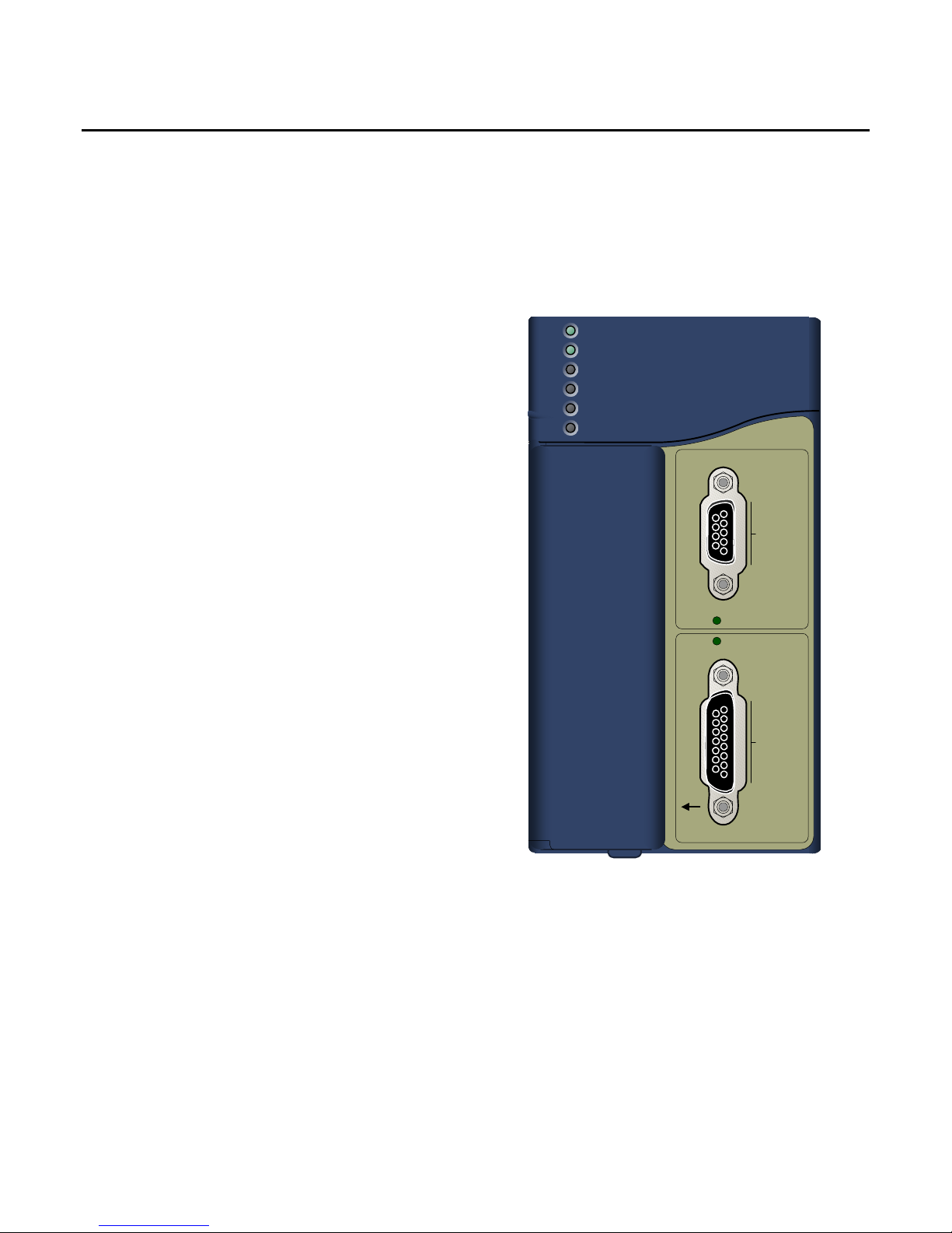
NIU OK
NIU SCANNING I/O
OUTPUTS ENABLED
I/O FORCE
BATTERY
SYSTEM
FAULT
RESET
RUN I/O
STOP
RUN OUTPUT DISABLE
ENABLE
IC695NIU001
NIU001
COM 1
▪ Optional Series 90-30 expansion backplanes.
▪ PACSystems RX3i and/or Series 90-30 modules, as
appropriate for the application.
The Ethernet NIU is compatible with the same types of
modules, backplanes, and other equipment as a
PACSystems RX3i CPU. For a list of compatible products,
see the PACSystems RX3i Hardware and Installation
Manual, GFK-2314.
This module requires Machine Edition Logic Developer
software, version 5.51 or later.
COM1 ACTIVE
COM1 ACTIVE
Ethernet NIU Features
▪
20Kbytes of optional local logic. Supports all
languages except C programming.
▪ 10 Mbytes of built-in flash memory for local user data
storage.
▪ Battery-backed calendar clock.
▪ In-system upgradeable firmware.
▪ Two serial ports: an RS-485 serial port and an
RS-232 serial port.
▪ Supports Ethernet communications via the backplane-
based Ethernet Interface module (IC695ETM001)
▪ Data exchange using Ethernet Global Data (EGD)
▪ TCP/IP communication services using SRTP
▪ Comprehensive station management and diagnostic
tools
▪ Supports operation with redundant controllers
COM 2
BATT
Ethernet Global Data Features
The Ethernet NIU communicates with its controller via
Ethernet Global Data exchanges. One exchange is used to
send outputs to the ENIU and another exchange is used to
send inputs back to the controller. The ENIU supports
receiving outputs from redundant controllers. By sending the
EGD exchange to a group address both controllers can
receive the inputs. Up to 1300 bytes of outputs can be sent to
a set of ENIUs from a controller. Each ENIU can send up to
1300 bytes of inputs to the controller.
A typical system might consist of a controller with five ENIUs.
The controller sends 1300 bytes of outputs and each ENIU

2 RX3i Ethernet NIU
T
C
GFK-2419M
sends 100 bytes of inputs to the controller. This typical
system would have its I/O updates occur in less than 25
milliseconds. If the controller scan time is greater than 25
milliseconds, the update occurs at the controller’s scan
rate. This performance timing is a guideline, not a
guarantee, and assumes that there is no other traffic on
the Ethernet link to the I/O. More performance data for
other system configurations can be found in the Ethernet
NIU Manual, GFK-2196A or later.
ENIU COMMREQ Feature
The ENIU supports selected COMMREQs that are sent to
it by a “C” block application in a PACSystems Rx7i or RX3i
controller. Ladder code is written in the RX7i or RX3i to
interface to the “C” block which results in COMMREQ
commands being sent via a EGD Exchange to the ENIU.
The ENIU executes the COMMREQ and sends the results
back to the RX7i or RX3i via another EGD exchange.
The following COMMREQs are supported:
▪ Modbus Master – function codes 1, 2, 3, 4, 5, 6, 7, 15,
16, 17
▪ Genius – enable/disable outputs, switch BSM, clear
fault, clear all faults, assign monitor, read diagnostic
▪ PROFIBUS Master – Commreqs 1, 2, 4, 5, 6
▪ Motion (DSM314/DSM324) – load parameters
▪ High Speed Counter – Data command
▪ DeviceNet Master – Commreqs 1, 4, 5, 6, 7, 9
▪ Analog Module – HART Protocol Commreqs
Operation, Protection, and Module
Status
Operation of this module can be controlled by the threeposition RUN/STOP switch or remotely by an attached
programmer and programming software. Program and
configuration data can be locked through software
passwords. The status of the NIU is indicated by the eight
NIU LEDs on the front of the module. (See “LED
Operation”).
Battery
A three-cell lithium battery pack (IC698ACC701) is
installed as show below. The battery maintains data
memory when power is removed and operates the
calendar clock. Program and initial values are always
loaded from flash when the ENIU powers up. When
replacing the battery, be sure to install a new battery
before disconnecting the old one. If a new battery is
installed when no battery is currently installed, the new
battery must be installed while the CPU has power.
Otherwise, the CPU may not power up. If that happens,
remove the battery, power-cycle the
CPU, then reinstall the battery.
Disposal of lithium batteries
must be done in accordance with
federal, state, and local
regulations. Be sure to consult
with the appropriate regulatory
agencies before disposing of
batteries.
To avoid loss of RAM memory
contents, routine maintenance
procedures should include
scheduled replacement of the NIU’s
lithium battery pack. For information
on estimating battery life, refer to
the PACSystems NIU Reference
Manual, GFK-2222.
RESE
A
B
Installation
It is the responsibility of the OEM, system integrator, or end
user to properly install the control system equipment for safe
and reliable operation. Installation should not be attempted
without referring to the PACSystems RX3i Hardware and
Installation Manual, GFK-2314.
1. Make sure that backplane power is off.
2. Install the NIU module in backplane 0. The NIU requires
two slots and can use any slots except the highest
numbered (rightmost) slot. It is recommended that the
ENIU be located in slots 2 and 3. For more information
about choosing a slot for the ENIU, see below.
3. Turn on power. The module should power up. When the
NIU has successfully completed initialization, the NIU OK
LED stays on and the NIU SCANNING I/O and EN LEDs
are off.
4. To save battery life, do not connect the battery for the first
time until the ENIU is installed in the backplane and the
backplane powered on. The battery may then be
attached to either of the two terminals in the battery
compartment. Once that is done, the ENIU may be
powered down and normal battery back up operation will
begin.
Backplane Locations for the ENIU
1. The A/C Power Supply (IC695PSAx40) for the RX3i is a
doublewide module whose connector is left-justified as
viewed when installed in a backplane. It cannot be
located in slot 11 of a 12-slot backplane or slot 15 of a
16-slot backplane. No latch mechanism is provided for
the last (rightmost) slot in a backplane, so it is not

RX3i Ethernet NIU 3
GFK-2419M
possible to place the power supply in the second to
last slot.
2. The RX3i ENIU (IC695NIU001) is a doublewide
module whose connector is right justified as viewed
when installed in a backplane. The ENIU is
referenced for configuration and application logic by
the leftmost slot occupied by the entire module, not by
the slot the physical connector is located in. For
example, if the ENIU has its physical connector
inserted in slot 3, the module occupies slots 2 and 3
and the ENIU is referenced as being located in slot 2.
▪ The ENIU may be located in slot 0 with its
connector in slot 1.
▪ The ENIU cannot be located in slot 11 of a 12-
slot backplane or in slot 15 of a 16-slot
backplane, because its connector cannot be
installed in the slot reserved for an expansion
module.
3. When migrating a Series 90-30 ENIU system to a
PACSystems RX3i ENIU, maintaining the slot 1
location of the ENIU means that only a singlewide
power supply may be used in slot 0. Either DC power
supply can be used (IC695PSD040 or
IC695PSD140). Therefore, if the application must
maintain a slot 1 ENIU and uses an AC power-supply,
the RX3i system must have the RX3i AC powersupply located in a slot to the right of the RX3i ENIU
in slot 1.
Locating the ENIU in a Slot Other than 1
Before deciding to place the ENIU in a slot other than slot
1, it is important to consider the possible application
migration issues that could arise, as explained below.
Application Program
For Service Request #15 (Read Last-Logged Fault Table
Entry) and Service Request #20 (Read Fault Tables), the
location of ENIU faults is not the standard 0.1 location, but
the slot the ENIU is located in (see above). Logic that
decodes fault table entries retrieved by these service
requests may need updating.
COMMREQs directed to the ENIU (e.g. those directed to
the serial ports of the ENIU) will need to be updated with
the correct ENIU slot reference.
Fault Tables
Faults logged for the ENIU in the fault table will not in the
standard 0.1 (backplane.slot) location, but will reflect the
ENIUs actual slot.
Series 90 Controllers
Remote Series 90 controllers that use SRTP Channels
COMMREQs expect the ENIU to be in slot 1 or slot 2. To
support communications with Series 90 SRTP clients such as
Series 90 controllers using SRTP Channels, the RX3i
internally redirects incoming SRTP requests destined for
{backplane 0, slot 1} to {backplane 0, slot 2}, provided that the
ENIU is located in backplane 0 slot 2 (and the remote client
has not issued an SRTP Destination service on the
connection to discover the backplane and slot of the ENIU).
This special redirection permits Series 90-30 applications that
expect the power supply to be located leftmost and the ENIU
to be located to the right of the power supply to function.
Attempts to establish channels with ENIUs in slots other than
1 or 2 will fail if initiated from Series 90 controllers.
HMI and External Communication Devices
All external communication devices that interact with the ENIU
should be checked for compatibility with ENIU slot locations
other than slot 1. Problems may arise with, but are not limited
to, initial connection sequences and fault reporting. Machine
Edition View users should select “GE SRTP” as their
communications driver – it can communicate with an ENIU in
any slot.
Programmer Connection
The programmer can communicate with the NIU via serial port
1, serial port 2, or the backplane-based Ethernet interface.
Connecting a programmer via an Ethernet TCP/IP network
requires a CAT5 standard Ethernet cable with RJ-45
connectors.
Before connecting the programmer and ENIU to the Ethernet
TCP/IP network, set the IP address using the Initial IP
Address software tool. After setting the IP address, connect
the RX3i and the computer running the programming software
to the Ethernet Interface. For detailed information on
programmer connection via Ethernet TCP/IP, refer to the
TCP/IP Ethernet Communications for PACSystems User’s
Manual, GFK-2224.
Hardware Configuration
The slot location of the ENIU must be updated in the
hardware configuration to reflect the ENIU’s true location.
4 RX3i Ethernet NIU
GFK-2419M
Firmware Upgrades
The ENIU uses non-volatile flash memory for storing the
operating system firmware. This allows firmware to be
updated without disassembling the module or replacing
EPROMs.
To install a firmware upgrade, connect WinLoader to the
NIU RS-232 or RS-485 serial port. When connecting
directly to the NIU, there is no need to specify the
Backplane/Slot location. For upgrades to Intelligent Option
modules (the IC695ETM001, for example), which are
performed indirectly via the NIU serial port, you must
specify a backplane/slot location.
Serial Ports
The NIU has two independent, on-board serial ports,
accessed by connectors on the front of the module. These
ports provide serial interfaces to external devices.
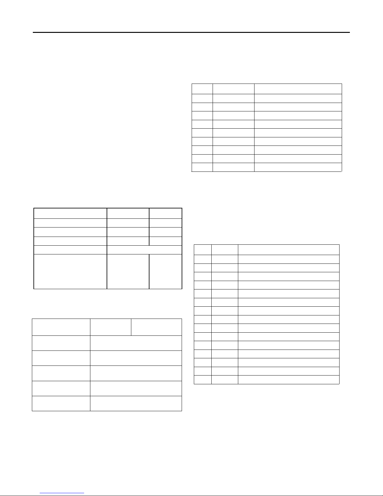
Protocols Supported
Protocol Port 1 Port 2
RTU (slave) Yes Yes
SNP Slave Yes Yes
Serial I/O * Yes Yes
Firmware Upgrade ENIU in STOP/No I/O mode
Message Mode
(C Runtime Library
Functions:
serial read, serial write,
sscanf, sprintf)
* Modbus Master is supported in application code in Serial
I/O mode.
Serial Port Baud Rates
Protocol
Modbus RTU Slave
protocol
Message 1200, 2400, 4800, 9600, 19.2K,
Firmware Upgrade
via Winloader
SNP Slave 1200, 2400, 4800, 9600, 19.2K,
Serial I/O 1200, 2400, 4800, 9600, 19.2K,
Port 1
Port 1 (COM1) is RS-232 compatible. It has a 9-pin,
female, D-sub connector with a standard pin out. This is a
DCE (data communications equipment) port that allows a
Yes Yes
Port 1
(RS-232)
1200, 2400, 4800, 9600, 19.2K,
38.4K, 57.6K, 115.2K
38.4K, 57.6K, 115.2K
2400, 4800, 9600, 19.2K, 38.4K,
57.6K, 115.2K
38.4K, 57.6K, 115.2K
38.4K, 57.6K, 115.2K
Port 2
(RS-485)
simple straight-through cable to connect with a standard ATstyle RS-232 port. The COM1 Active LED provides the status
of serial port activity.
Port 1 RS-232 Signals
Pin Signal Description
1* NC No Connection
2 TXD Transmit Data
3 RXD Receive Data
4 DSR Data Set Ready
5 0V Signal Ground
6 DTR Data Terminal Ready
7 CTS Clear To Send
8 RTS Request to Send
9 NC No Connection
* Pin 1 is at the bottom right of the connector as viewed from the
front of the module.
Port 2
Port 2 (COM2) is RS-485 compatible. Port 2 has a 15-pin,
female D-sub connector. This port supports the RS-485 to
RS-232 adapter (IC690ACC901). This is a DCE port. The
COM2 Active LED provides the status of serial port activity.
Port 2 RS-485 Signals
Pin Signal Description
1* Shield Cable Shield
2 NC No Connection
3 NC No Connection
4 NC No Connection
5 +5VDC Logic Power**
6 RTS(A) Differential Request to Send
7 0V Signal Ground
8 CTS(B‘) Differential Clear To Send
9*** RT Resistor Termination
10** RD(A‘) Differential Receive Data
11 RD(B‘) Differential Receive Data
12 SD(A) Differential Send Data
13 SD(B) Differential Send Data
14 RTS(B) Differential Request To Send
15 CTS(A’) Differential Clear To Send
* Pin 1 is at the bottom right of the connector as viewed from
the front of the module.
** Pin 5 provides isolated +5VDC power (300mA maximum)
for powering external options.
*** Termination resistance for the RD A’ signal should be
connected on units at the end of the line. To make this
termination, connect a jumper between pins 9 and 10
inside the 15-pin D-shell.
 Loading...