

Page 1
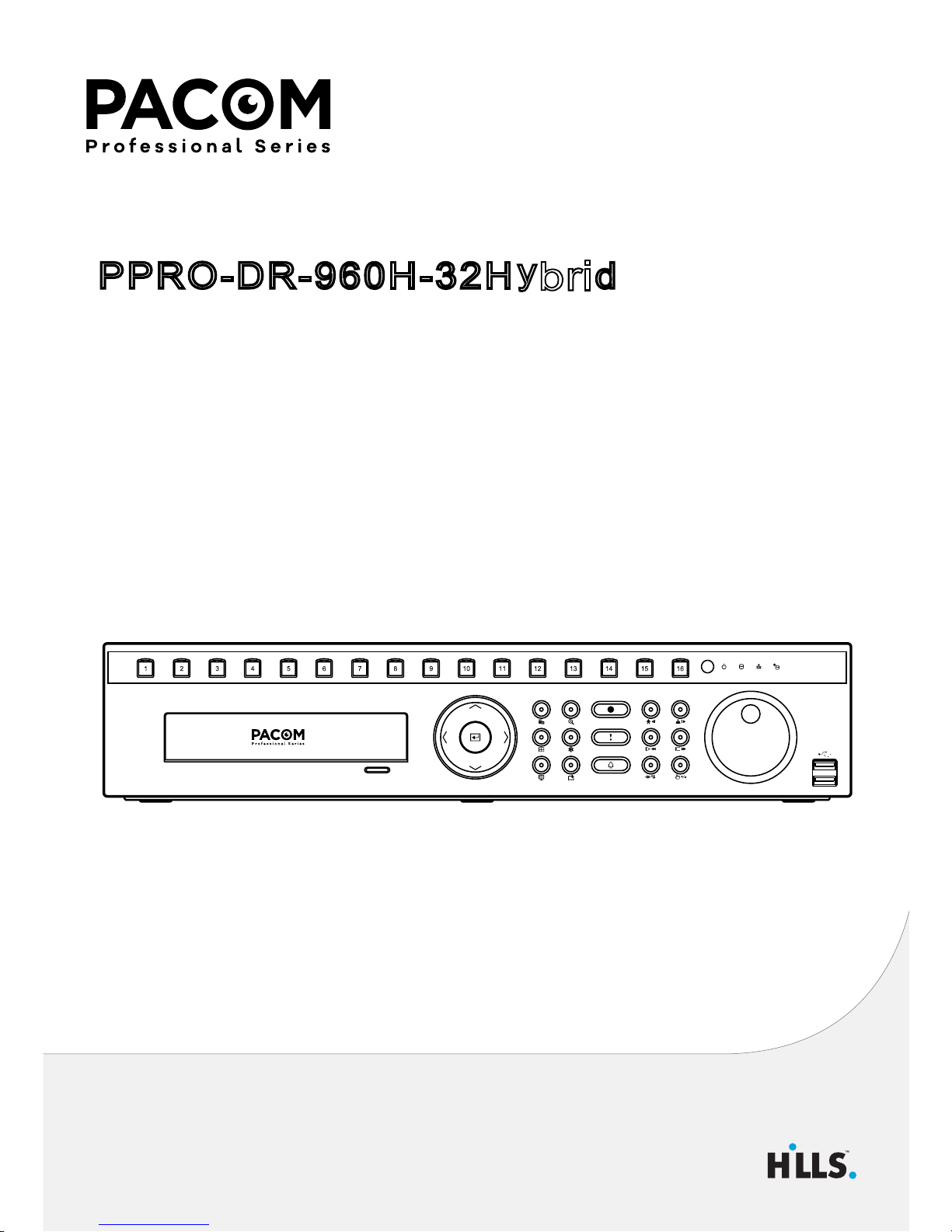
PPRO-DR-960H-32H
y
d
(S55942)
32 Channel Hybrid Network Video Recorder
Quick Guide
Hybrid Network Video Recorder
ri
b
Page 2

2
Safety Precautions
Important Safeguards
1. Read Instructions
All the safety and operating instructions should be read before the
appliance is operated.
2. Retain Instructions
The safety and operating instructions should be retained for future
reference.
3. Cleaning
Unplug this equipment from the wall outlet before cleaning it. Do not use
liquid aerosol cleaners. Use a damp soft cloth for cleaning.
4. Attachments
Never add any attachments and/or equipment without the approval of the
manufacturer as such additions may result in the risk of re, electric shock or
other personal injury.
5. Water and/or Moisture
Do not use this equipment near water or in contact with water.
6. Ventilation
Place this equipment only in an upright position. This equipment has an
open-frame Switching Mode Power Supply (SMPS), which can cause a re
or electric shock if anything is inserted through the ventilation holes on the
side of the equipment.
7. Accessories
Do not place this equipment on an unstable cart, stand or table. The
equipment may fall, causing serious injury to a child or adult, and serious
damage to the equipment. Wall or shelf mounting should follow the
manufacturer’s instructions, and should use a mounting kit approved by
the manufacturer.
This equipment and cart combination should be moved with care. Quick
stops, excessive force, and uneven surfaces may cause the equipment and
cart combination to overturn.
8. Power Sources
This equipment should be operated only from the type of power source
indicated on the marking label. If you are not sure of the type of power,
please consult your equipment dealer or local power company.
please consult your equipment dealer or local power company.
You may want to install a UPS (Uninterruptible Power Supply) system for
safe operation in order to prevent damage caused by an unexpected power
stoppage. Any questions concerning UPS, consult your UPS retailer.
9. Power Cords
Operator or installer must remove power and TNT connections before
handling the equipment.
10. Lightning
For added protection for this equipment during a lightning storm, or when
it is left unattended and unused for long periods of time, unplug it from the
wall outlet and disconnect the antenna or cable system. This will prevent
damage to the equipment due to lightning and power-line surges.
11. Overloading
Do not overload wall outlets and extension cords as this can result in the risk
of re or electric shock.
12. Objects and Liquids
Never push objects of any kind through openings of this equipment as they
may touch dangerous voltage points or short out parts that could result in a
re or electric shock. Never spill liquid of any kind on the equipment.
13. Servicing
Do not attempt to service this equipment yourself. Refer all servicing to
qualied service personnel.
14. Damage requiring Service
Unplug this equipment from the wall outlet and refer servicing to qualied
service personnel under the following conditions:
A. When the power-supply cord or the plug has been damaged.
B. If liquid is spilled, or objects have fallen into the equipment.
C. If the equipment has been exposed to rain or water.
D. If the equipment does not operate normally by following the operating
instructions, adjust only those controls that are covered by the operating
instructions as an improper adjustment of other controls may result in
damage and will often require extensive work by a qualied technician to
restore the equipment to its normal operation.
E. If the equipment has been dropped, or the cabinet damaged.
F. When the equipment exhibits a distinct change in performance - this
indicates a need for service.
15. Replacement Parts
When replacement parts are required, be sure the service technician has
used replacement parts specied by the manufacturer or that have the
same characteristics as the original part. Unauthorized substitutions may
result in re, electric shock or other hazards.
16. Safety Check
Upon completion of any service or repairs to this equipment, ask the service
technician to perform safety checks to determine that the equipment is in
proper operating condition.
17. Field Installation
This installation should be made by a qualied service person and should
conform to all local codes.
18. Correct Batteries
Warning: Risk of explosion if battery is replaced by an incorrect type.
Replace only with the same or equivalent type. Dispose of used batteries
according to the instructions. The battery shall not be exposed to excessive
heat such as sunshine, re or the like.
19. Tmra
A manufacturer’s maximum recommended ambient temperature (Tmra)
for the equipment must be specied so that the customer and installer may
determine a suitable maximum operating environment for the equipment.
20. Elevated Operating Ambient Temperature
If installed in a closed or multi-unit rack assembly, the operating ambient
temperature of the rack environment may be greater than room ambient.
Therefore, consideration should be given to installing the equipment in an
environment compatible with the manufacturer’s maximum rated ambient
temperature (Tmra).
21. Reduced Air Flow
Installation of the equipment in the rack should be such that the amount of
airow required for safe operation of the equipment is not compromised.
22. Mechanical Loading
Mounting of the equipment in the rack should be such that a hazardous
condition is not caused by uneven mechanical loading.
23. Circuit Overloading
Consideration should be given to connection of the equipment to supply
circuit and the eect that overloading of circuits might have on over current
protection and supply wiring. Appropriate consideration of equipment
nameplate ratings should be used when addressing this concern.
24. Reliable Earthing (Grounding)
Reliable grounding of rack mounted equipment should be maintained.
Particular attention should be given to supply connections other than direct
connections to the branch circuit (e.g., use of power strips).
Page 3
3
CAUTION
RISK OF ELECTRIC SHOCK
DO NOT OPEN
CAUTION:
TO REDUCE THE RISK OF ELECTRIC SHOCK,
DO NOT REMOVE COVER (OR BACK).
NO USER-SERVICEABLE PARTS INSIDE.
REFER SERVICING TO QUALIFIED SERVICE PERSONNEL.
The lightning ash with arrowhead symbol, within an equilateral triangle, is intended to alert the user to the presence of uninsulated "dangerous
voltage" within the product’s enclosure that may be of sucient magnitude to constitute a risk of electric shock.
The exclamation point within an equilateral triangle is intended to alert the user to the presence of important operating and maintenance
(servicing) instructions in the literature accompanying the appliance.
Symbol Publication Description
IEC60417, No.5032 Alternating current
FCC Compliance Statement
THIS EQUIPMENT HAS BEEN TESTED AND FOUND TO COMPLY WITH THE LIMITS FOR A CLASS A DIGITAL DEVICE, PURSUANT TO PART 15 OF THE FCC RULES. THESE
LIMITS ARE DESIGNED TO PROVIDE REASONABLE PROTECTION AGAINST HARMFUL INTERFERENCE WHEN THE EQUIPMENT IS OPERATED IN A COMMERCIAL
ENVIRONMENT. THIS EQUIPMENT GENERATES, USES, AND CAN RADIATE RADIO FREQUENCY ENERGY AND IF NOT INSTALLED AND USED IN ACCORDANCE WITH
THE INSTRUCTION MANUAL, MAY CAUSE HARMFUL INTERFERENCE TO RADIO COMMUNICATIONS. OPERATION OF THIS EQUIPMENT IN A RESIDENTIAL AREA IS
LIKELY TO CAUSE HARMFUL INTERFERENCE, IN WHICH CASE USERS WILL BE REQUIRED TO CORRECT THE INTERFERENCE AT THEIR OWN EXPENSE.
WARNING
: CHANGES OR MODIFICATIONS NOT EXPRESSLY APPROVED BY THE PARTY RESPONSIBLE FOR COMPLIANCE COULD VOID THE USER’S AUTHORITY
TO OPERATE THE EQUIPMENT. THIS CLASS OF DIGITAL APPARATUS MEETS ALL REQUIREMENTS OF THE CANADIAN INTERFERENCE CAUSING EQUIPMENT
REGULATIONS.
WEEE (Waste Electrical & Electronic Equipment)
Correct Disposal of This Product
(Applicable in the European Union and other European countries with separate collection systems)
This marking shown on the product or its literature, indicates that it should not be disposed with other household wastes at the end of its
working life. To prevent possible harm to the environment or human health from uncontrolled waste disposal, please separate this from other
types of wastes and recycle it responsibly to promote the sustainable reuse of material resources.
Household users should contact either the retailer where they purchased this product, or their local government oce, for details of where and
how they can take this item for environmentally safe recycling.
Business users should contact their supplier and check the terms and conditions of the purchase contract. This product should not be mixed
with other commercial wastes for disposal.
Copyright
© 2016 Pacic Communications
Pacic Communications reserves all rights concerning this operation manual.
Use or duplication of this operation manual in part or whole without the prior consent of Pacic Communications is strictly prohibited.
Contents of this operation manual are subject to change without prior notice for reasons such as functionality enhancements.
The information in this manual is believed to be accurate as of the date of publication even though explanations of some functions may not be included. We
are not responsible for any problems resulting from the use thereof. The information contained herein is subject to change without notice. Revisions or new
editions to this publication may be issued to incorporate such changes.
This product contains software built partially on open-source content. Codes for the corresponding open-source content are available for download. For more
information, refer to the software CD (OpenSourceGuide\OpenSourceGuide.pdf) or the open source guide accompanying this operation manual.
Page 4
4
Accessories
Upon unpackaging the product, check the contents inside to ensure that all the following accessories are included.
Item
Network Video Recorder Power Cable Quick Guide Rack-mount Kit
Operation Manual and RASplusIP Program CD Optical USB Mouse IR Remote Control Multi audio cable
Assembly Screws for Adding Hard Disk Drives SATA2 Cables
Overview
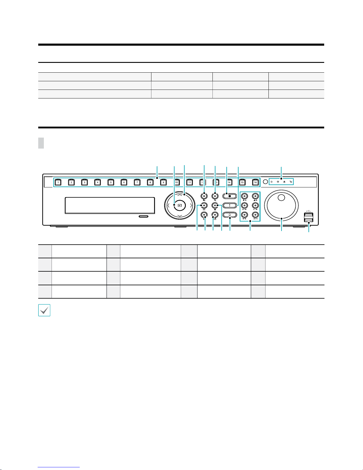
Front Panel
1
2 3
4 5 6 7
8
90!
@
# $
%
^
1
Camera Buttons
2
Enter Button
3
Arrow Buttons
4
Menu Button
5
Zoom Button
6
PTZ Button
7
Panic Recording
Button
8
LEDs
9
Display Button
0
Status Button
!
Bookmark Button
@
Freeze Button
#
Alarm Button
$
Playback Control
Buttons
%
Jog Dial, Shuttle
Ring
^
USB Ports
For more details on USB ports and LEDs of the front panel, refer to the operation manual.
Page 5
5
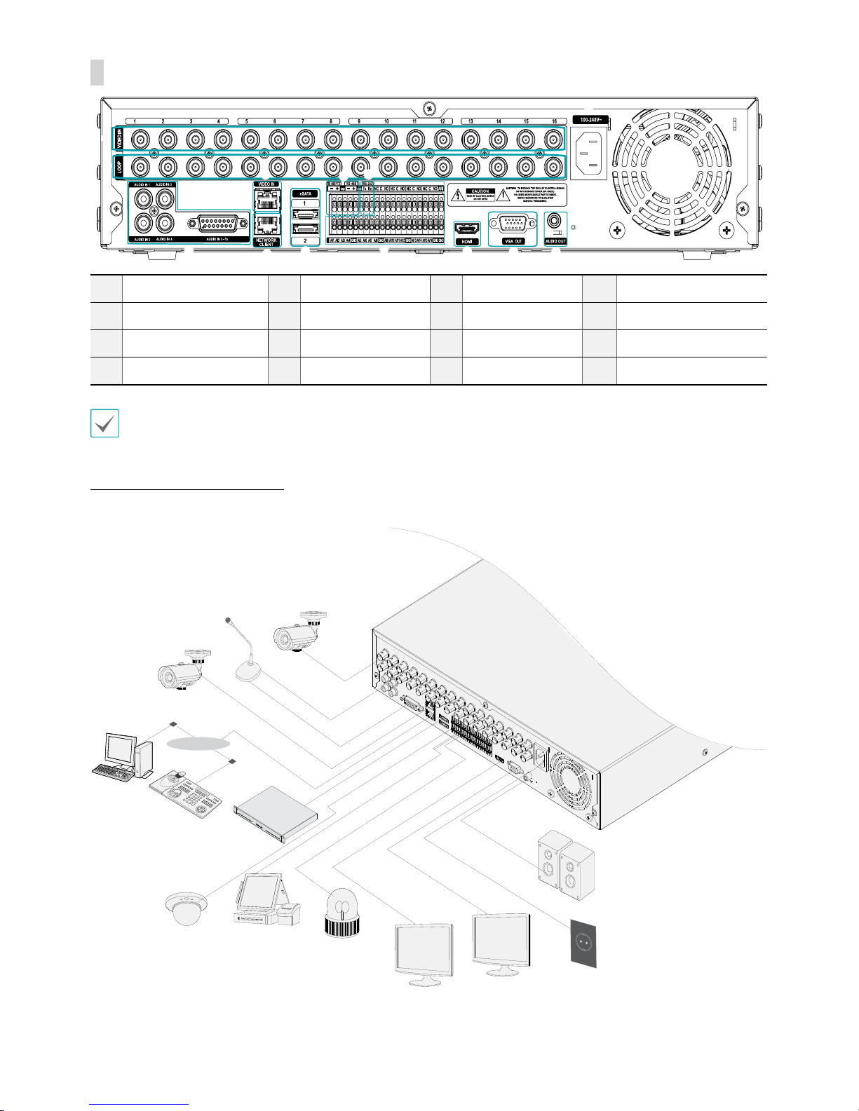
Rear Panel
1
2
3
4
5
6
7 8
9
0
!
@
#
1
Video Input
2
Video Loop Through
3
Audio In
4
Video In Port
5
Network Port
6
eSATA Ports
7
RS-485 Port
8
RS-232 Port
9
Alarm Connection Ports
0
HDMI Out Port
!
VGA Out Port
@
Audio Out Port
#
Power In Port
For more details on rear panel connections, refer to the operation manual.
Connections on the Rear Panel
Speaker
VGA Monitor
HDMI Monitor
Network
Camera
RASplusIp
Remote
Monitoring
Keyboard
Sensor
Alarm
Power
POS
eSATA
Storage Device
Network
Analog
Camera
Microphone
Page 6
6
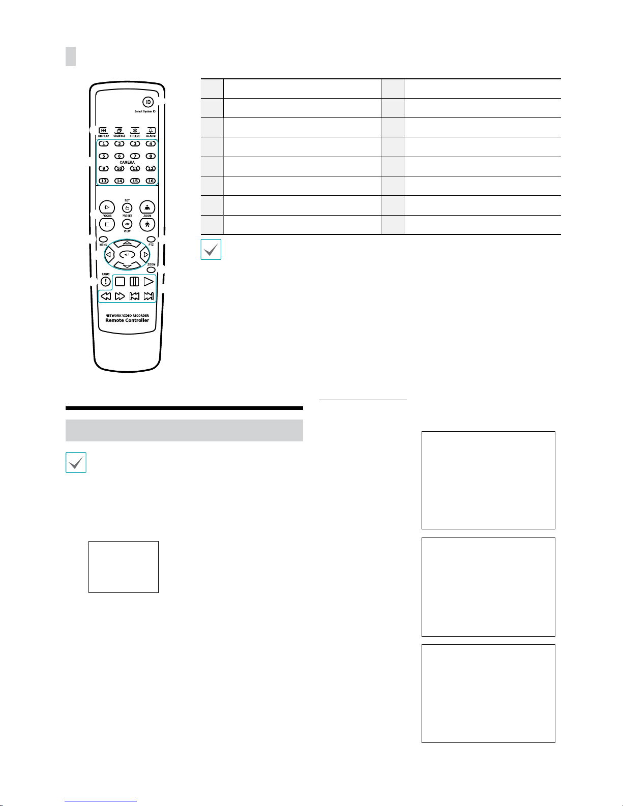
Remote Control
@
!
#
$
%
^
3
1
2 4
5
6
7
8
9
0
1
ID Button
2
Display Button
3
Sequence Buttons
4
Freeze Button
5
Alarm Button
6
Camera Buttons
7
Focus near/far Button
8
Preset set/view Button
9
Zoom in/out Button
0
Menu Button
!
PTZ Button
@
Arrow Button
#
Enter Button
$
Zoom Button
%
Panic Buttons
^
Playback Buttons
For more details on remote control buttons, refer to the operation manual.
Getting Started
Setup Wizard
• Setup Wizard only appears during initial booting.
When you login as an administrator account after
initial booting, you can use Wizard to go to Live menu
and select Wizard.
• For more details on Setup Wizard, refer to the
operation manual.
1
Select a system language.
Quick Setup Wizard
● Start the Quick Setup Wizard
● Date/Time Setup
The new date and time
settings will only be
applied after clicking
Next.
● Record Method
Setup
● Record Video
Quality Setup
Higher recording quality
uses up more disk space.
● Finish the Quick Setup Wizard
Page 7
7
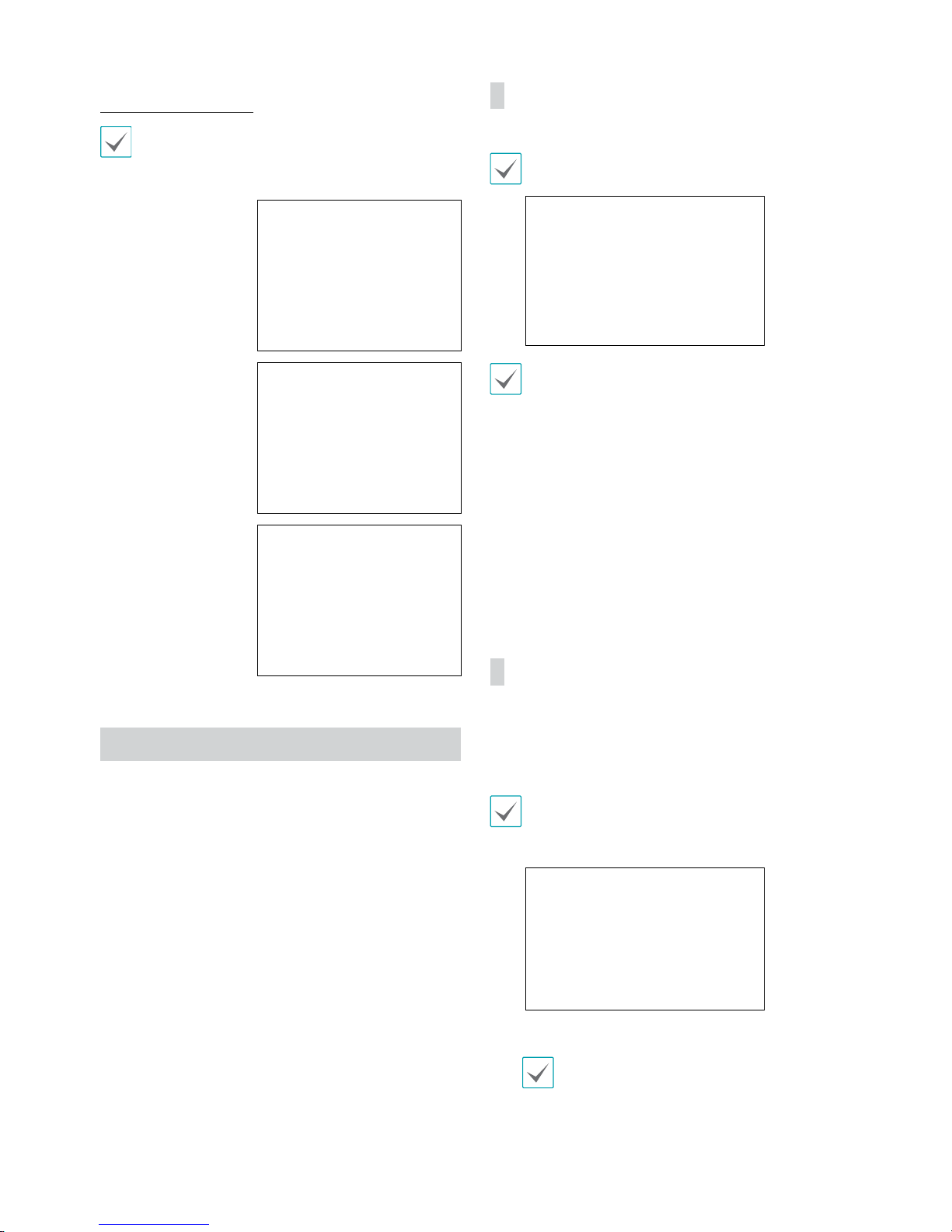
Network Setup Wizard
After exiting from Quick Wizard, the network with
Network Wizard will start automatically.
● Start the Network Setup Wizard
● Internet
Connection
● LAN Setup
This test must be
performed before
proceeding to the next
step.
● FEN Setup
Enter the NVR name
registered on the FEN
server in the Device
Name eld, and click
the Check to check its
availability.
● Finish the Network Setup Wizard
Camera Registration
Once Network Setup Wizard is complete, 16-channel analog
cameras are automatically registered and click the Scan
button to scan for network cameras connected to NVR. By
deleting some or all of the 16 registered analog cameras,
you can register analog and/or network IP cameras, up to
32 cameras (User determines exact combination with a
maximum of 16 analog inputs).
Device Scan
Click the “Scan” button and the Device Scan screen
Some functions may not be supported for the third
party cameras depending on their protocol and moel.
Even if the network device uses a protocol
supported by the NVR, the device itself may not
be visible for scanning and registration by the
NVR. For more information about supported
network devices and models, contact your
retailer.
● Mode: Select the scan mode.
1
Mac Address:
Displays the last 6 digits of the camera’s
MAC address.
2 Address
: Indicates the camera’s searched IP address.
3 Model
: Indicates the network camera’s model or “analog”
if they are the analog cameras.
4 Name
: Indicates the camera’s name.
5 Status
: Identies the camera’s registration status
“registered” or “not registered.”
Advanced Setup: Video In IP Setup
If the camera is networked but not scanned, use this setup.
This setup allows you to change the network setting
of the NVR’s VIDEO IN port which is camera’s network
environment. Check the camera’s network setting rst
before you use this setup.
Make sure that this setting does not conict with
the WAN setting. For more information on the WAN
setting, refer to the operation manual.
1
Select Scan to commence scanning.
Only cameras that are connected to the NVR via
VIDEO IN ports can be scanned and registered.
2
Select a camera from the scan list and then select Add
Camera. The device login window will appear.
3
Enter a User ID and a Password for the selected
camera.
Page 8
8
Login
Conguring the NVR’s settings and accessing its searching
and other functions require an authorized user login.
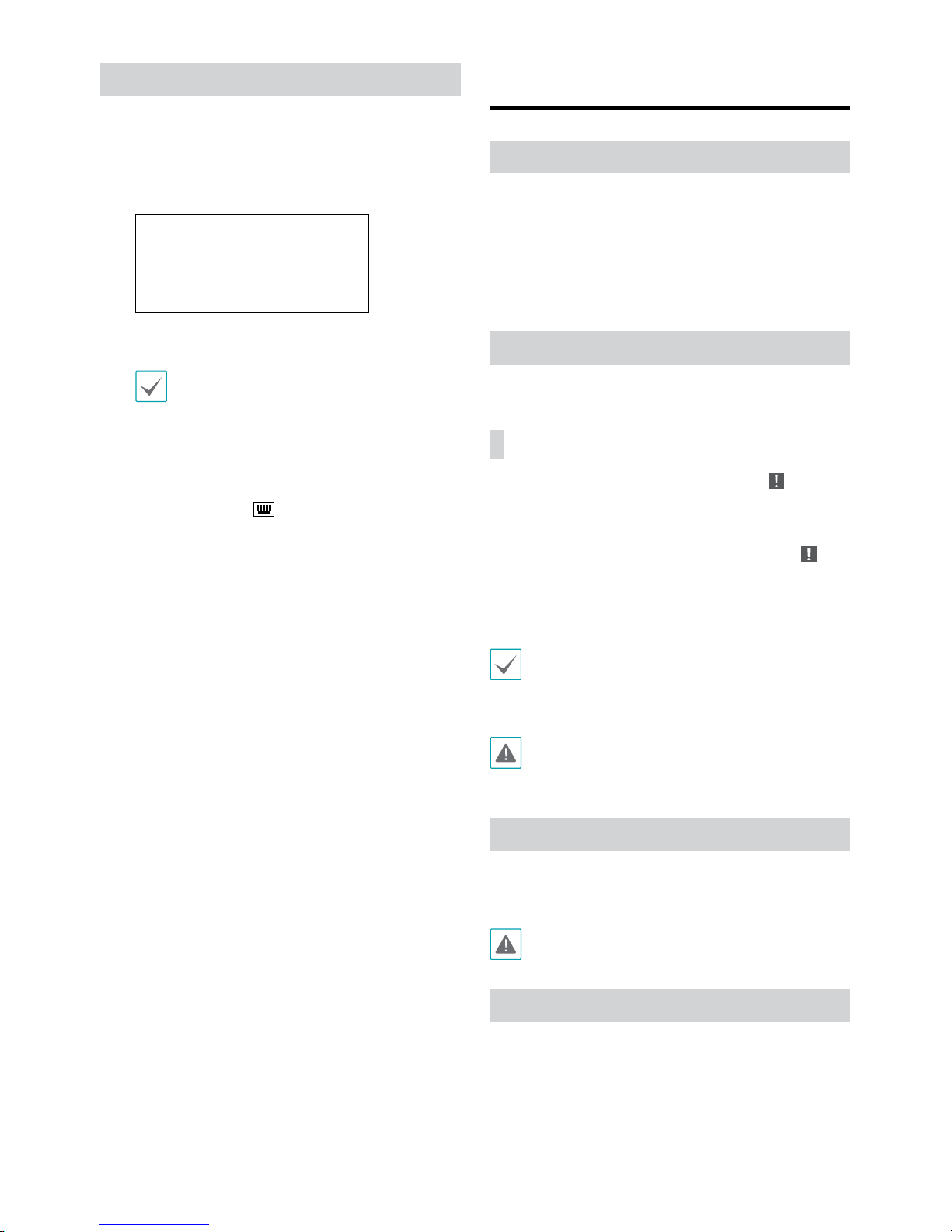
1
While in Live mode, right-click on the mouse and
select Login and either press the SETUP button on
the remote control.
2
Select a user, enter the password, and then select OK.
• There is no default password for the admin
account. Select admin and then OK without
entering a password to log in.
• Leaving the admin account unassigned with
a password poses a security risk. Please assign
a password at your earliest convenience. A
warning message will continue to be displayed
until a password is assigned.
• Click on the
button next to the password
eld using the mouse. This will bring up a
virtual keyboard you can use to assign a
password.
3
To log out, right-click on the mouse and select
Logout.
Basic Feature
Live Mode
Once Camera Registration is complete, the system will enter
Live Mode.
Press the Setup button while in Live mode to bring up
the Live menu on the top of the screen. Press Setup once
more to hide the menu. Use the Arrow buttons on the front
panel of the NVR or the remote control to select the menu
options.
Video Recording
Records the live video.
Refer to the Operation Manual for more information.
Panic Recording
Select Live or Search menu's Panic Recording icon or
press the Panic Recording button on the front panel or
the remote control to commence panic recording on all
registered cameras.
To stop Panic Recording, select the Panic Recording
icon
or press the Panic Recording button again. If the Panic
Recording Time option under Record Setup > General
has been congured, Panic Recording will automatically
terminate after the specied duration of time has elapsed.
• Panic Recording takes place irrespective of any
recording schedule set up by the user.
• Panic Recording video prole from Record Setup –
General applies to all Panic Recording videos.
Panic Recording will not take place if recording mode
is not set to Recycle and the HDD has reached 100%
of its capacity.
Audio Recording
If the Record Audio option under Record Setup > General
has been enabled the camera will record audio along with
video.
Check your local laws and regulations on making
audio recordings.
Video Recording Playback
You can play back video recordings by using a mouse or
remote control.
Page 9
9
All Channel Playback
1
Press the Menu button while in Live mode.
2
Select the Search Mode icon and then select Record
Table Search or Event Log Search.
3
The selected search mode will be initiated.
WebGuard
WebGuard is a program that allows you to view and search
video from remote locations over the Internet and can
be accessed on a regular web browser such as Internet
Explorer.
System requirements for running WebGuard are as follows:
Recommended
OS
Microsoft
®
Windows® XP (Service Pack 3),
Microsoft
®
Windows® Vista (Service Pack 1),
Microsoft
®
Windows® 7 (Home Premium,
Professional, Ultimate) or Microsoft
®
Windows®
8 (Pro, Enterprise)
CPU
Intel Pentium IV 2.4GHz or above
(Core 2 Duo E4600 recommended)
RAM 1GB or more
VGA
128MB or more (1280x1024, 24bpp or above)
Internet Explorer
Ver. 7.0 or above (32-Bit)
• WebGuard only works with Microsoft Internet
Explorer and will NOT work with other browsers.
• WebGuard does not work in Microsoft
®
Windows®
8 metro UI.
Setup WebGuard
1
Launch Internet Explorer and then enter the following
information in the address bar.
– http://IP Address:Port Number (NVR system’s IP
address and WebGuard port number congured
under Network > General (Default Value: 12088))
– Or http://FEN server address/FEN Name (FEN
Name: NVR name congured on the FEN server)
– Or http://www.dvronline.net (will be prompted to
enter NVR’s IP address or FEN name registered to
the FEN server upon login)
Contact your network administrator for the IP address
of the NVR you wish to connect to and the WebGuard
port number.
2
When prompted with the WebGuard login window,
select WEBWATCH or WEBSEARCH as the desired
mode. Enter the ID and password and click LOGIN
to sign in using the selected mode. If connecting by
entering http://www.dvronline.net, enter the NVR’s IP
address in the Device Address eld.
Selecting the Use DVRNS option on the login window
allows you to enter the NVR name registered to
the FEN server instead of its IP address. You will be
prompted to enter the FEN server’s address and port
number under Setup.
RASplusIP Program
System Requirements
Recommended Minimum
OS
Microsoft
®
Windows® 7 x86
(64bit) (Home Premium,
Professional, Ultimate)
Microsoft
®
Windows® 8 (pro,
Enterprise)
Microsoft
®
Windows® XP
Home SP3
CPU
Intel CoreTM i5-2550 3.30GHz
or better
Intel CoreTM 2 Duo E7200
2.53GHz or better
RAM 2GB or more
1.5GB or more
VGA
ATI RadeonTM HD 3650 or
NVIDIA GeForce 8400GS or
better (1280x1024, 32bpp or
better), multiple monitors
ATI RadeonTM HD 2400 or
NVIDIA GeForce FX5500 or
better (1024x768, 24bpp or
better)
HDD 6GB or more of available space 1GB or more of available space
LAN Gigabit Ethernet or better
10/100 Mbps Ethernet or
better
• RASplusIP program runs on 32-bit OS.
• On 64-bit versions of Microsoft
®
Windows® Vista
or later, RASplusIP installs and runs in 32-bit
compatibility mode.
Installation
Prior to installing the software, click on to the Windows
Start menu, open Control Panel, click on Power
Management, and set options for Turn o monitor and
Turn o hard disks as Never.
1
Please enter the software installation CD into the PC.
2
Browse to the Setup folder in the CD and run setup.
exe.
Page 10

10
On Microsoft® Windows® Vista or User
Account Control window may pop-up.
Click Allow and follow the instructions in
the installation window to proceed with the
installation.
3
When the installation window appears, click Next.
4
Select an installation path for the program, and click
Next.
5
When the install conrmation window appears, click
Next.
NET Framework and Visual C++ Runtime
Libraries will be installed automatically, and
it may take a few minutes. If NET Framework
and Visual C++ Runtime Libraries are already
installed on the system, this step will be
skipped automatically.
6
When the Installation Completed window appears,
click Close and nish the installation.
Start Program
When RASplusIP software is installed, RASplusIP and
RASplusIP Run as administrator shortcut icons will be
created on the desktop. Run RASplusIP software by doubleclicking on RASplusIP or RASplusIP Run as administrator
shortcut icon. If a removable eSATA HDD or SD (SDHC)
memory card are connected to the RASplusIP system, you
must double-click on RASplusIP Run as administrator.
Login
This program does not have a password set by default.
Leaving the admin account unassigned with a password
poses a security risk. Please assign a password at your
earliest convenience.
Once the program is running, you must login.
Enter a User ID and Password.
● Remember my ID on this computer: Remembers the ID
used to login.
● Restore last Live sessions: Restores the previous Live
session on the current Live panel.
• Default User ID is "admin" without a password.
• You can change User ID and Password in the User
menu.
Device Registration
To use the functions provided by RASplusIP, you must rst
register a device and add the device to a device group.
1
Select System > RASplusIP Setup > Device in the
menu at the top of the screen.
2
On the Site panel, click on All Devices, then click on
the
button at the bottom of the Site List panel on
the right. A Device Scan window will appear on the
screen.
3
After selecting a scan mode, click on Start Scan
button and the scan results will be displayed on the
list.
4
Click Add Devices at the bottom of the Device Scan
window.
5
When user authentication window appears, enter the
User ID and Password set up on each device, and then
select OK for remote access.
Page 11
11
6
Click Device Group on the Sites panel and click
at
the bottom. Add Device Group window will appear.
● Name: Enter a name for the device group.
● Location: Select an location for the subject device
group.
When you select a device from the device List on the
left, it will be added to the Selected Device List on
the right. Click OK to register the device group.
7
Make sure that the device has been added to the
device group correctly. Click Device Group on the
Sites panel and click on next to Device Group. When
you click on a registered device group, a list of devices
added the selected device group will be displayed on
the right.
To modify a device group that has been registered,
select a device group and click
on the bottom of
the Sites panel. Modify Device Group window will
appear. You can modify the selected device group
from this window.
Live Video Mode
1
In the Site List, make sure that the device has been
added to the device group.
2
In the panel tabs, click the Live tab. In the Site list,
select a zone you wish to connect to. Then, drag &
drop the selected site on the Live screen using your
mouse. The live video of the selected site will be
displayed on the screen.
Recorded Video Playback
1
In the Site List, make sure that the device has been
added to the device group.
2
In the panel tabs, click on the Play tab. In the Site list,
select a site you wish to connect to. Then, drag & drop
the selected site on the playback screen using your
mouse.
The recorded video of the selected site will be
displayed on the screen.
PDR-mobile
This service requires heavy data trac, and using a
Wi-Fi connection is recommended. Using wireless
internet (3G, LTE) may result in excessive data charges.
Android OS device
1
Open the Play Store(Google Play) on your Android
device.
2
In Play Store (Google Play), enter aPDR-mobile in the
search eld.
3
Install aPDR-mobile program and open it.
4
The start-up menu appears when pressing the Menu
button on your mobile device.
5
Register the device by pressing New Site and entering
the device (network camera) information.
– Description: Enter a name of the device to be used
in aPDR-mobile app.
– Use DVRNS: Select the check box. Deselect the
checkbox if FEN is not enabled on the device. If
the device is using an additional FEN server, press
Settings in the start-up menu and enter the FEN
server information. (Default site: dvrnames.net,
Default port number: 10088). For more details,
contact your FEN server administrator.
Page 12
12
– Address, Watch Port, Search Port: Enter the
device name used to register the device to FEN. If
FEN feature is not enabled on the device, deselect
DVRNS checkbox and enter the device's IP
address. For port number, using the default value is
recommended.
– User ID, Password: Enter the User ID and Password
used to login to the device. (Default value of User
ID: admin, No default value of password)
iOS device
1
Open the App Store on your device.
2
Enter iPDR-mobile in the search led of the App
Store.
3
Install iPDR-mobile program and open it.
4
Register the device by pressing + button and entering
the device (NVR) information.
– General: Enter a name of the device to be used in
iPDR-mobile app.
– Connection Info: Turn DVRNS ON and enter the
device name used to register the device to the
FEN. If FEN feature is not enabled on the device,
turn DVRNS OFF and enter the device's IP address.
For port number, using the default value is
recommended.
– Login Info: Enter the User ID and Password used
to login to the device. (Default value of User ID:
admin, No default value of password).
Specications
These product specications may change without prior
notice.
General
Exterior Dimensions
(W x H x D)
430mm x 88mm x 414.8mm
Weight (Main Unit) 5.9kg (with 1HDD)
Working Temperature 0°C – 40°C
Operating Humidity 0% – 90%
Power 100-240V~
Power Consumption 75W (with 6HDDs)
Certications FCC, CE, UL, CB, PSE
Video
Video In
32 cameras (Up to 16 BNC, Up to 32 IP
cameras)
Monitor Out
HDMI: 1 HDMI
VGA: 1 DB15
Video Resolution
1920 x 1200, 1920 x 1080, 1680 x 1050,
1600 x 1200
Recording Speed (IPS)
960ips @ Full HD
Playback Speed (IPS) 120ips @ Full HD
I/O
Alarm In
16 TTL, NC/NO programmable,
2.4V (NC) or 0.3V (NO) threshold, 5VDC
Alarm Out
4 relay outputs, NC/NO, 2A@125VAC,
1A@30VDC
Alarm Reset In 1 TTL, terminal block
Internal Buzzer 78dB at 10cm
Network Connection 10Mbps/100Mbps/1Gbps Ethernet
Audio In 16 lines, RCA
Audio Out 1 line, RCA
Tex t I n POS Interface, ATM Interface
Connector
Video In
Ethernet: 1 port, Composite: 16 BNC
Camera Power Out
Composite: 16 BNC
Monitor Out
HDMI: 1 HDMI
VGA: 1 DB15
Audio In 16 RCA connectors
Audio Out 1 RCA connector
Alarm Terminal block
Ethernet Port 1 RJ-45
eSATA Ports 2 eSATA ports
RS-232 Serial Port Terminal block, text insertion (POS/ATM)
RS-485 Serial Port
Terminal block, telemetry control, remote
control keyboard (programmable)
IR Remote Control Port
Remote Control
USB Ports 2 x USB 2.0 (5V, less than 0.5A)
Storage
Internal Storage 6 SATA2 bays (RAID)
External Storage 2 eSATA ports
Clip Copy Device
USB Storage Device (USB HDD, USB
Memory, etc.)
V1.1
Page 13

Proudly distributed by
 Loading...