

Page 1

Page 2

Page 3
Network Video Recorder
i
WARNING
RISK OF ELECTRIC SHOCK
DO NOT OPEN
WARNING: TO REDUCE THE RISK OF ELECTRIC SHOCK,
DO NOT REMOVE COVER (OR BACK).
NO USER-SERVICEABLE PARTS INSIDE.
REFER SERVICING TO QUALIFIED
SERVICE PERSONNEL.
The lightning flash with arrowhead symbol, within an equilateral triangle, is intended to alert
the user to the presence of uninsulated "dangerous voltage" within the product's enclosure
that may be of sufficient magnitude to constitute a risk of electric shock.
The exclamation point within an equilateral triangle is intended to alert the user to the
presence of important operating and maintenance (servicing) instructions in the literature
accompanying the appliance.
COMPLIANCE NOTICE OF FCC:
THIS EQUIPMENT HAS BEEN TESTED AND FOUND TO COMPLY WITH THE LIMITS FOR A CLASS A DIGITAL
DEVICE, PURSUANT TO PART 15 OF THE FCC RULES. THESE LIMITS ARE DESIGNED TO PROVIDE
REASONABLE PROTECTION AGAINST HARMFUL INTERFERENCE WHEN THE EQUIPMENT IS OPERATED IN
A COMMERCIAL ENVIRONMENT. THIS EQUIPMENT GENERATES, USES, AND CAN RADIATE RADIO
FREQUENCY ENERGY AND IF NOT INSTALLED AND USED IN ACCORDANCE WITH THE INSTRUCTION
MANUAL, MAY CAUSE HARMFUL INTERFERENCE TO RADIO COMMUNICATIONS. OPERATION OF THIS
EQUIPMENT IN A RESIDENTIAL AREA IS LIKELY TO CAUSE HARMFUL INTERFERENCE, IN WHICH CASE
USERS WILL BE REQUIRED TO CORRECT THE INTERFERENCE AT THEIR OWN EXPENSE.
WARNING: CHANGES OR MODIFICATIONS NOT EXPRESSLY APPROVED BY THE PARTY RESPONSIBLE
FOR COMPLIANCE COULD VOID THE USER’S AUTHORITY TO OPERATE THE EQUIPMENT.
THIS CLASS OF DIGITAL APPARATUS MEETS ALL REQUIREMENTS OF THE CANADIAN INTERFERENCE-
CAUSING EQUIPMENT REGULATIONS.
The information in this manual is believed to be accurate as of the date of publication. We are not responsible for any
problems resulting from the use thereof. The information contained herein is subject to change without notice. Revisions
or new editions to this publication may be issued to incorporate such changes.
The software included in this product contains some Open Sources. You may obtain the complete corresponding
source code from us. See the Open Source Guide on the software CD (OpenSourceGuide\OpenSourceGuide.pdf)
or as a printed document included along with the User's Manual.
Page 4

User’s Manual
ii
Important Safeguards
1. Read Instructions
All the safety and operating instructions should be read before the
appliance is operated.
2. Keep Instructions
The safety and operating instructions should be kept for future
reference.
3. Cleaning
Unplug this equipment from the wall outlet before cleaning it. Do
not use liquid aerosol cleaners. Use a damp soft cloth for cleaning.
4. Attachments
Never add any attachments and/or equipment without the approval
of the manufacturer as such additions may result in the risk of fire,
electric shock or other personal injury.
5. Water and/or Moisture
Do not use this equipment near water or in contact with water.
6. Accessories
Do not place this equipment on an unstable cart, stand or table. The
equipment may fall, causing serious injury to a child or adult, and
serious damage to the equipment. Wall or shelf mounting should
follow the manufacturer's instructions, and should use a mounting
kit approved by the manufacturer.
This equipment and cart combination should be moved with care.
Quick stops, excessive force, and uneven surfaces may cause the
equipment and cart combination to overturn.
7. Ventilation
Slots and openings in the cabinet and the back or bottom are provided
for ventilation, and to ensure reliable operation of the equipment and
to protect it from overheating. These openings must not be blocked
or covered. Do not block these openings or allow them to be blocked
by placing the equipment on a bed, sofa, rug, or bookcase. Ensure that
there is adequate ventilation and that the manufacturer’s instructions
have been adhered to.
8. Power Sources
This equipment should be operated only from the type of power source
indicated on the marking label. If you are not sure of the type of
power, please consult your equipment dealer or local power company.
9. Power Cords
Operator or installer must remove power and other connections before
handling the equipment.
10. Lightning
For added protection for this equipment during a lightning storm,
or when it is left unattended and unused for long periods of time,
unplug it from the wall outlet and disconnect the antenna or cable
system. This will prevent damage to the equipment due to lightning
and power-line surges.
11. Overloading
Do not overload wall outlets and extension cords as this can result
in the risk of fire or electric shock.
12. Objects and Liquids
Never push objects of any kind through openings of this equipment
as they may touch dangerous voltage points or short out parts that
could result in a fire or electric shock. Never spill liquid of any kind
on the equipment.
13. Servicing
Do not attempt to service this equipment yourself. Refer all servicing
to qualified service personnel.
14. Damage requiring Service
Unplug this equipment from the wall outlet and refer servicing to
qualified service personnel under the following conditions:
A. When the power-supply cord or the plug has been damaged.
B. If liquid is spilled, or objects have fallen into the equipment.
C. If the equipment has been exposed to rain or water.
D. If the equipment does not operate normally by following the
operating instructions, adjust only those controls that are covered
by the operating instructions as an improper adjustment of other
controls may result in damage and will often require extensive work
by a qualified technician to restore the equipment to its normal
operation.
E. If the equipment has been dropped, or the cabinet damaged.
F. When the equipment exhibits a distinct change in performance —
this indicates a need for service.
15. Replacement Parts
When replacement parts are required, be sure the service technician
has used replacement parts specified by the manufacturer or that have
the same characteristics as the original part. Unauthorized substitutions
may result in fire, electric shock or other hazards.
16. Safety Check
Upon completion of any service or repairs to this equipment, ask
the service technician to perform safety checks to determine that the
equipment is in proper operating condition.
17. Field Installation
This installation should be made by a qualified service person and
should conform to all local codes.
18. Telnet Communication Cable
Caution: To reduce the risk of fire, use only No. 26 AWG or larger
telecommunication line cord.
19. Danger of explosion if battery is incorrectly replaced. Replace
only with same or equivalent type recommended by manufacturer.
Discard used batteries according to the manufacturer’s instruction.
WEEE (Waste Electrical & Electronic Equipment)
Correct Disposal of This Product
(Applicable in the European Union and other European countries with separate collection systems)
This marking shown on the product or its literature, indicates that it should not be disposed with other household wastes at the
end of its working life. To prevent possible harm to the environment or human health from uncontrolled waste disposal, please
separate this from other types of wastes and recycle it responsibly to promote the sustainable reuse of material resources.
Household users should contact either the retailer where they purchased this product, or their local government office, for
details of where and how they can take this item for environmentally safe recycling.
Business users should contact their supplier and check the terms and conditions of the purchase contract. This product should
not be mixed with other commercial wastes for disposal.
Page 5

Network Video Recorder
iii
Table of Contents
Chapter 1 — Introduction ............................................................................................ 1
1.1 Features ............................................................................................................ 1
1.2 System Diagram ................................................................................................ 2
1.3 Rear Panel ........................................................................................................ 2
1.4 Front Panel ........................................................................................................ 3
1.5 Upgrade ............................................................................................................. 3
Remote Upgrade ............................................................................................... 4
1.6 Tuning On/Off the System ................................................................................. 7
Chapter 2 — Getting Started ....................................................................................... 9
2.1 Connecting ........................................................................................................ 9
2.2 System Setting ................................................................................................ 10
2.3 Registering Devices ........................................................................................ 13
2.4 Live Video Monitoring ...................................................................................... 17
2.5 Recording ........................................................................................................ 17
2.6 Playing Recorded Video .................................................................................. 18
Chapter 3 — System Overview ................................................................................. 19
3.1 Service Manager ............................................................................................. 19
Menu ............................................................................................................... 19
Status Display ................................................................................................. 20
Service Database Backup/Restore ................................................................. 21
Cascade .......................................................................................................... 22
3.2 Setup ............................................................................................................... 24
Service ............................................................................................................ 24
Device ............................................................................................................. 25
User ................................................................................................................. 27
Recording Schedule ........................................................................................ 27
Event Management ......................................................................................... 28
3.3 Client ............................................................................................................... 29
Menu ............................................................................................................... 31
Site List ........................................................................................................... 32
Panel ............................................................................................................... 33
Menu – Preference Settings ........................................................................... 34
Chapter 4 — Live Video Monitoring .......................................................................... 41
4.1 Monitoring Video ............................................................................................. 41
Layout Monitoring ........................................................................................... 43
Layout Sequence Monitoring .......................................................................... 44
Camera Sequence Monitoring ........................................................................ 47
4.2 Map Monitoring ............................................................................................... 48
4.3 Controlling Cameras ....................................................................................... 50
PTZ Control ..................................................................................................... 51
Zoom Control .................................................................................................. 52
Image Effect .................................................................................................... 53
Text-In Viewer ................................................................................................. 53
Page 6

User’s Manual
iv
4.4 Controlling Maps ............................................................................................. 53
Chapter 5 — Recording ............................................................................................. 57
5.1 Setting up Recording Schedule ...................................................................... 57
Setting up Time-Lapse Recording .................................................................. 59
Setting up Event-Based Recording ................................................................. 61
Managing Schedule ........................................................................................ 65
Setting up Instant Recording ........................................................................... 66
Chapter 6 — Recorded Video Playback & Exportation ............................................. 69
6.1 Playing back Recorded Video ......................................................................... 69
Snapshot on Motion Event .............................................................................. 73
Object/Motion Search ..................................................................................... 73
Zoom Control .................................................................................................. 74
Image Effect .................................................................................................... 75
6.2 Exporting Recorded Video .............................................................................. 75
Exporting as a Self-Player File ........................................................................ 75
Exporting as an AVI File ................................................................................. 78
Chapter 7 — Event Handling ..................................................................................... 81
7.1 Handling a Monitoring Event ........................................................................... 81
Monitoring Video ............................................................................................. 81
Playing Video .................................................................................................. 82
7.2 Handling Event Recorded Video ..................................................................... 83
Chapter 8 — Device Status Monitoring ..................................................................... 85
8.1 Health Monitoring ............................................................................................ 85
8.2 Device Check .................................................................................................. 86
8.3 Status Monitoring ............................................................................................ 87
Chapter 9 — Log Search ........................................................................................... 89
Chapter 10 — Streaming ........................................................................................... 91
Chapter 11 — Device Management .......................................................................... 93
11.1 Registering Devices ...................................................................................... 94
11.2 Managing Devices ......................................................................................... 98
Editing Device Information .............................................................................. 99
Changing Device’s Setting Remotely ........................................................... 102
Upgrading Device’s Software ........................................................................ 103
Checking Device Status ................................................................................ 103
Editing Input/Output Device Information ....................................................... 104
11.3 Remote Setup of ONVIF
TM
Conformance Protocol Devices ....................... 104
Chapter 12 — User Management ........................................................................... 111
Chapter 13 — Storage Management ...................................................................... 113
Chapter 14 — Event Management .......................................................................... 115
Page 7

Network Video Recorder
v
14.1 Setting up Event Management Schedule .................................................... 115
Managing Schedule ...................................................................................... 122
14.2 Managing Events ........................................................................................ 123
Live Popup .................................................................................................... 123
Event Acknowledgement .............................................................................. 124
Chapter 15 — Map Editor ........................................................................................ 127
15.1 Registering Map .......................................................................................... 127
15.2 Setting up Map ............................................................................................ 128
Chapter 16 — Controlling With a Network Keyboard .............................................. 131
16.1 Registering .................................................................................................. 131
16.2 Connecting .................................................................................................. 132
16.3 Operating..................................................................................................... 132
16.4 Network Keyboard Buttons ......................................................................... 134
Chapter 17 — Remote Monitoring ........................................................................... 137
17.1 Installation ................................................................................................... 137
17.2 Uninstall ....................................................................................................... 139
Appendix .................................................................................................................. 141
Schedule Setup Examples of Event Recording Mode ........................................ 141
OSD Information.................................................................................................. 143
Network Disconnection Log ................................................................................ 143
Troubleshooting................................................................................................... 144
Specification ............................................................................................................ 147
Index ........................................................................................................................ 149
Page 8

User’s Manual
vi
Page 9

Network Video Recorder
1
Chapter 1 — Introduction
1.1 Features
This network video recorder (NVR) provides monitoring of video from network video transmitters, network
cameras and DVRs, recording of monitoring video (DVR excluded) and playback of video recorded in the
NVR system or DVR.
Remote monitoring of live images
Remote monitoring of live images in multiple Client systems through a streaming service (the number
of channels that can be streamed equals the number of channels that can be recorded)
Up to 20 simultaneous connections to the NVR system
Software upgrades and multiple systems setup remotely (supported only for devices which provide the
functions)
Display of system log information (supported only for devices which use the SiRiS protocol)
Map monitoring of live images
Centralized system operation and management and event handling
Enhanced security using the SSL function
Two-way audio communication and audio broadcasting
Enhanced security by setting up different authorities for each user group
Controlling with a network keyboard
Text-in and alarm function via TCP networking
Intuitive GUI
The following are supported only for network cameras and network video transmitters:
− Recording of video and playback of the recorded video
− Instant Recording of monitored images
− Audio recording
− Stable recording using proprietary video database file system
The following are supported only for DVRs:
− Playback of video recorded in DVRs
− Remote control of panic recording
Number of devices that can be registered and channels that can be recorded and streamed:
− Registration: Maximum of 1,024 devices including devices which do not use the SiRiS protocol (The
devices which do not use the SiRiS protocol can be registered up to the maximum number of available
recording channels. For example, if the NVR system is a 16-channel model, up to 16 devices that do
not use the SiRiS protocol can be registered.)
− Recording (not supported for DVRs): Maximum of 16 (16-channel model) /32 (32-channel model) channels
− Streaming (not supported for DVRs): The number of channels that can be streamed equals the number
of channels that can be recorded.
NOTES:
In this document, the “remote system” refers to a network video transmitter or DVR which cameras are
connected to or a network camera. The “client system” refers to a PC running the Client program to
connect to the NVR system remotely.
If the device is a four-channel network video transmitter which uses the SiRiS protocol, all four cameras
are counted even if some of the four cameras are disabled, and four channels per network video transmitter
are deducted from the number of channels available for recording and streaming.
This document covers the 16- and 32-channel network video recorders. For simplicity, the illustrations
and descriptions in this document refer to the 32-channel model. Refer to Appendix (p. 141) for the
system specifications of each model.
Page 10
User’s Manual
2
NOTES:
This product includes software developed by the OpenSSL Project for use in the OpenSSL Toolkit
(http://www.openssl.org/).
The software included in this product contains some Open Sources. You may obtain the complete
corresponding source code from us. See the Open Source Guide on the software CD (OpenSourceGuide\
OpenSourceGuide.pdf) or as a printed document included along with this document.
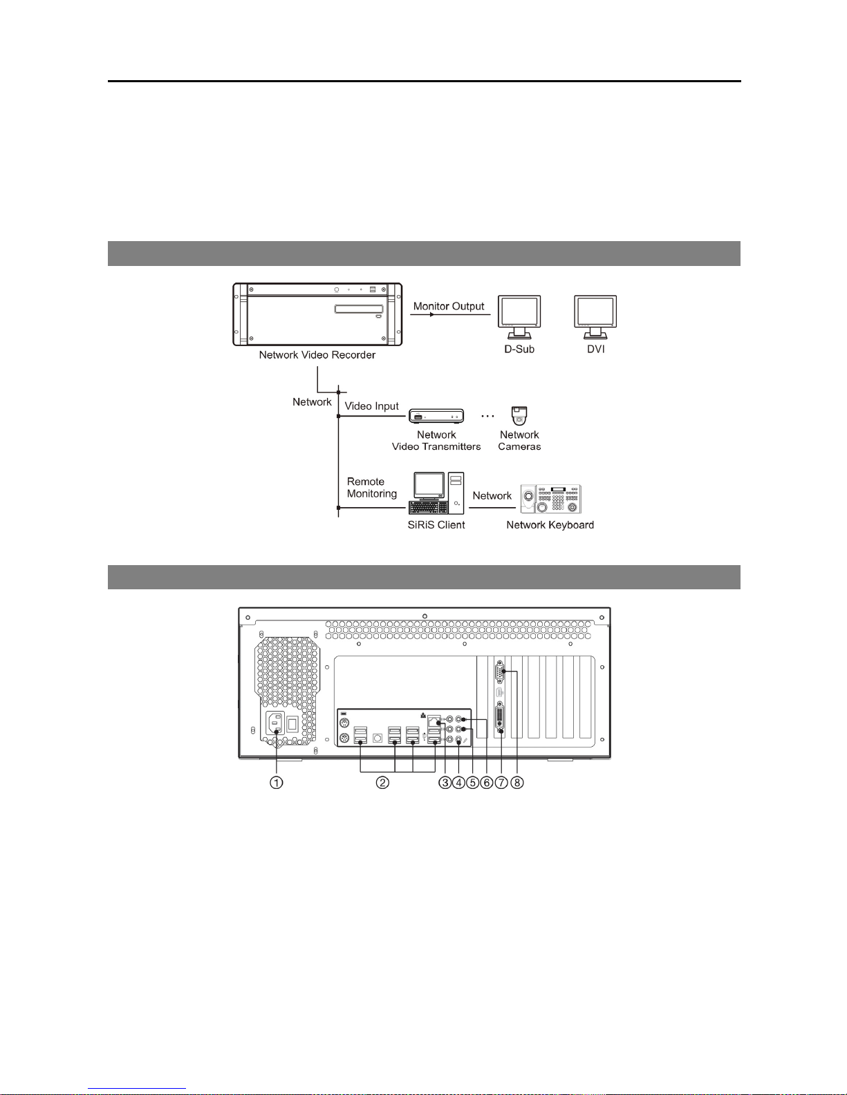
1.2 System Diagram
1.3 Rear Panel
① Power In: Connect a power cord.
② USB Port: Connect USB devices.
③ Network (RJ-45): Connect a Cat5 cable with an RJ-45 jack. Refer to 2.2 System Setting (p. 10) for
details about network setting.
④ Audio In (mic): Connect a microphone. This is for two-way audio communication.
⑤ Audio Out (Line out): Connect a speaker.
⑥ Audio In (Line in): Connect a line-in device. This is for two-way audio communication.
Page 11
Network Video Recorder
3
⑦ DVI: Connect a PC monitor. Connect a monitor before turning on the system. Video might not be
displayed on the monitor when connecting a monitor after turning on the system. Refer to 3.3 Client,
Menu – Preference Settings, Screen Format (p. 35) for details about the monitor setting.
⑧ D-Sub: Connect a PC monitor. Connect a monitor before turning on the system. Video might not be
displayed on the monitor when connecting a monitor after turning on the system. Refer to 3.3 Client,
Menu – Preference Settings, Screen Format (p. 35) for details about the monitor setting.
NOTE: The location of DVI and D-Sub connectors is subject to change without notice.
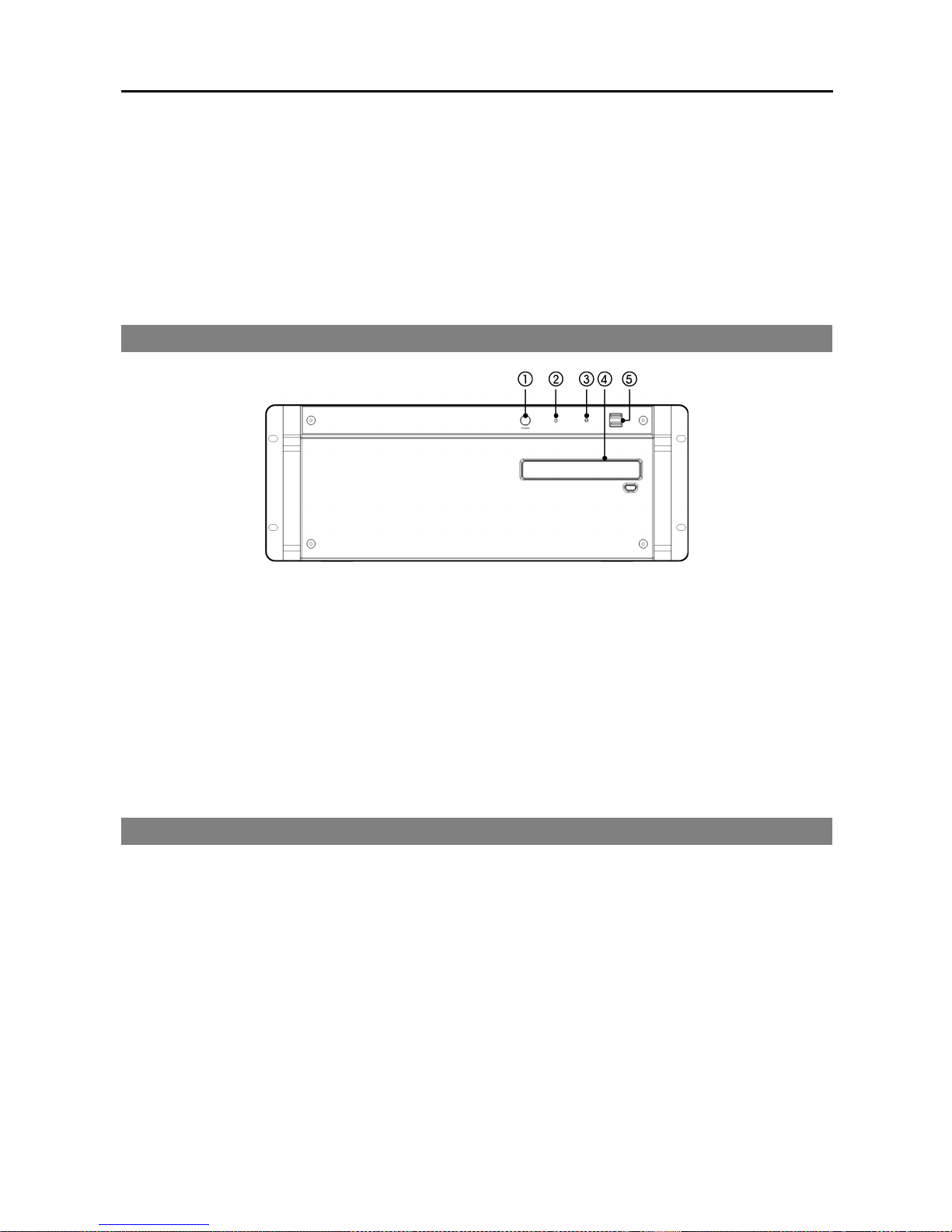
1.4 Front Panel
① Power Button: Turns on or off the system.
② Power LED: Is lit when the unit is turned on.
③ HDD LED: Flickers when the unit accesses to the hard disk drive.
④ DVD RW: Used to save the recorded data on the CD-RW or DVD RW media.
⑤ USB Port: Connects the USB devices.
NOTE: Windows may not operate properly when using the USB connectors on the front panel of the unit,
depending on the model type of the USB device. In this case, connect the USB device after Windows boots
properly or use the USB connectors located on the rear panel.
1.5 Upgrade
You can upgrade the NVR system by using a USB flash drive as follows:
NOTE: Upgrading by using a USB flash drive is supported for the users belonging to the default user group
(Administrators).
1. Connect a USB flash drive containing the upgrade package file to the NVR while the SiRiS Client program
is running.
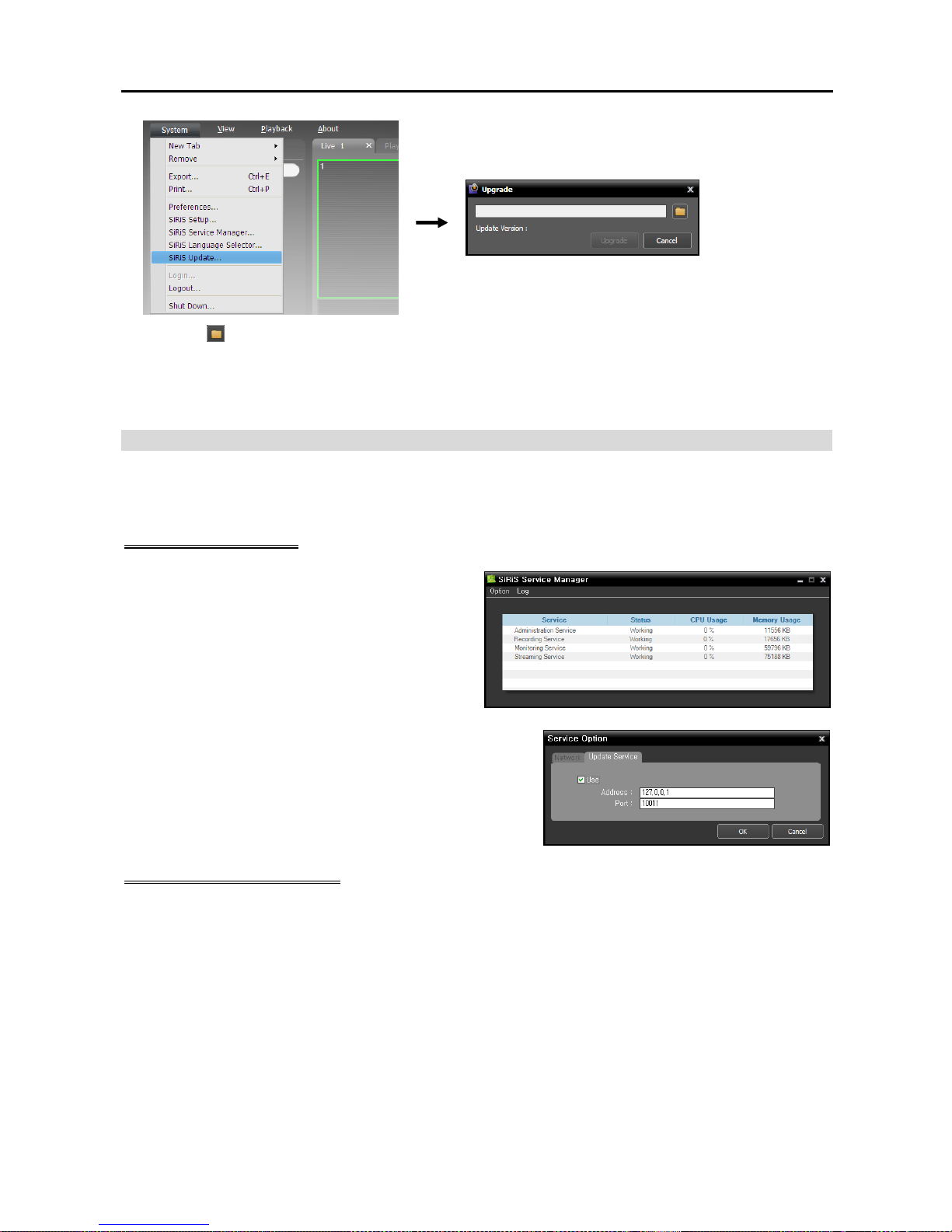
2. Click SiRiS Update under the System Menu in the NVR system. The following window appears.
Page 12
User’s Manual
4
Click the button and select a Standard.conf file. The folder path and software version of the selected
file is displayed. → Click the Upgrade button. → The SiRiS Client program closes and the NVR system
enters Windows mode. → The NVR system starts upgrading. When upgrade is complete, the SiRiS
program runs automatically.
Remote Upgrade
You can upgrade the NVR system remotely by using the installation file of the software version to upgrade
if an update service is running.
Update Service Setup
1. Run the Service Manager program in the NVR
system. Refer to 3.1 Service Manager (p. 19)
for details about running the Service Manager
program. Select the Administration Service in
the service list.
2. Click Option menu and select Update Package and then
select Update Service tab. Check the Use box and enter
the IP address and port number of the update server.
Update Service Installation
System Requirements
Operating System: Microsoft® Windows® XP 32-bit/Vista (Home Standard, Business, Ultimate, Enterprise),
Microsoft
®
Windows® 7 (Home Premium, Professional, Ultimate), Microsoft® Windows® 8 (Pro, Enterprise),
Microsoft
®
Windows® Server 2003/2008
CPU: Intel Core II Quad 8200 2.33 GHz/Intel Xeon 3.0 GHz or faster
RAM: 2GB or more
VGA: ATI Radeon
TM
HD 2400 or NVIDIA GeForce FX5500 (ATI recommended) (1024x768, 24bpp
or higher)
Hard Disk Drive: 5 GB or more free space for each service (for example, 10 GB or more free space when
installing administration and monitoring services)
LAN: Gigabit Ethernet or faster
Page 13
Network Video Recorder
5
NOTES:
The SiRiS program operates under 32 bit operating system. When you install it under 64 bit of Microsoft
®
Windows
®
Vista or later operating system, it is installed and operates in 32 bit compatibility mode.
Disable your PC’s Windows power saving function: Start menu → Power Options → set both Turn off the
display and Put the computer to sleep to Never (Power Options → Power Schemes tab → set both Turn
off monitor and Turn off hard disks to Never when using the Microsoft
®
Windows® XP operating system).
1. Insert the software CD in the update server.
2. Run the PNVRUpdateServiceSetup.exe file in the Setup folder of the software CD.
NOTE: The User Account Control window might appear when using the Microsoft® Windows® Vista or later
operating system. Click Allow and install the software following the instructions.
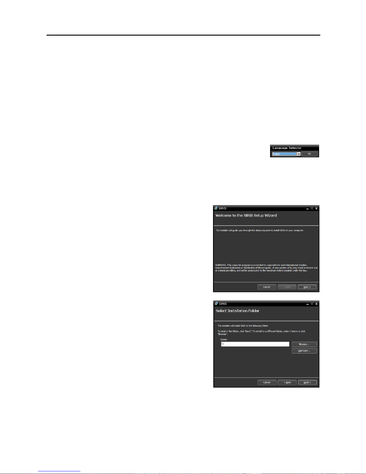
3. Select the language in which to run the program and then click OK.
NOTES:
To properly display the selected language, your PC’s operating system should be set to support the
selected language.
To change the SiRiS program’s language after the software has been installed, select Language Selector
in the SiRiS → Utility folder of the Start menu before running the SiRiS Setup program.
4. When the following screen appears, click Next.
5. Designate the folder path to install the service. Clicking the
Disk Cost… button shows the available and required disk
space for each hard disk drive for the installation. Then click
Next.
Page 14
User’s Manual
6
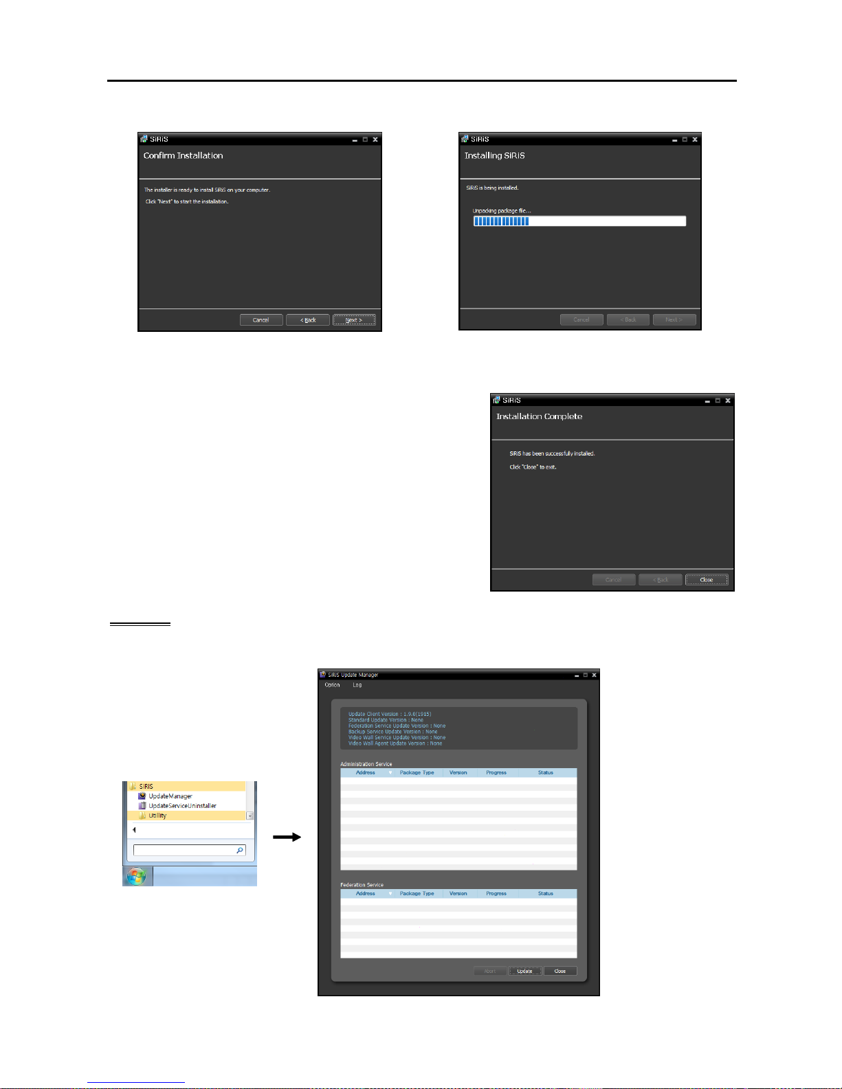
6. When the following screens appear, click Next.
NOTE: .NET Framework and the Visual C++ Runtime Libraries are installed automatically, and it may take
some time. This installation step will be skipped if the programs are already installed on your computer
.
7. When the following screen appears, click the Close button
to complete the installation.
Upgrade
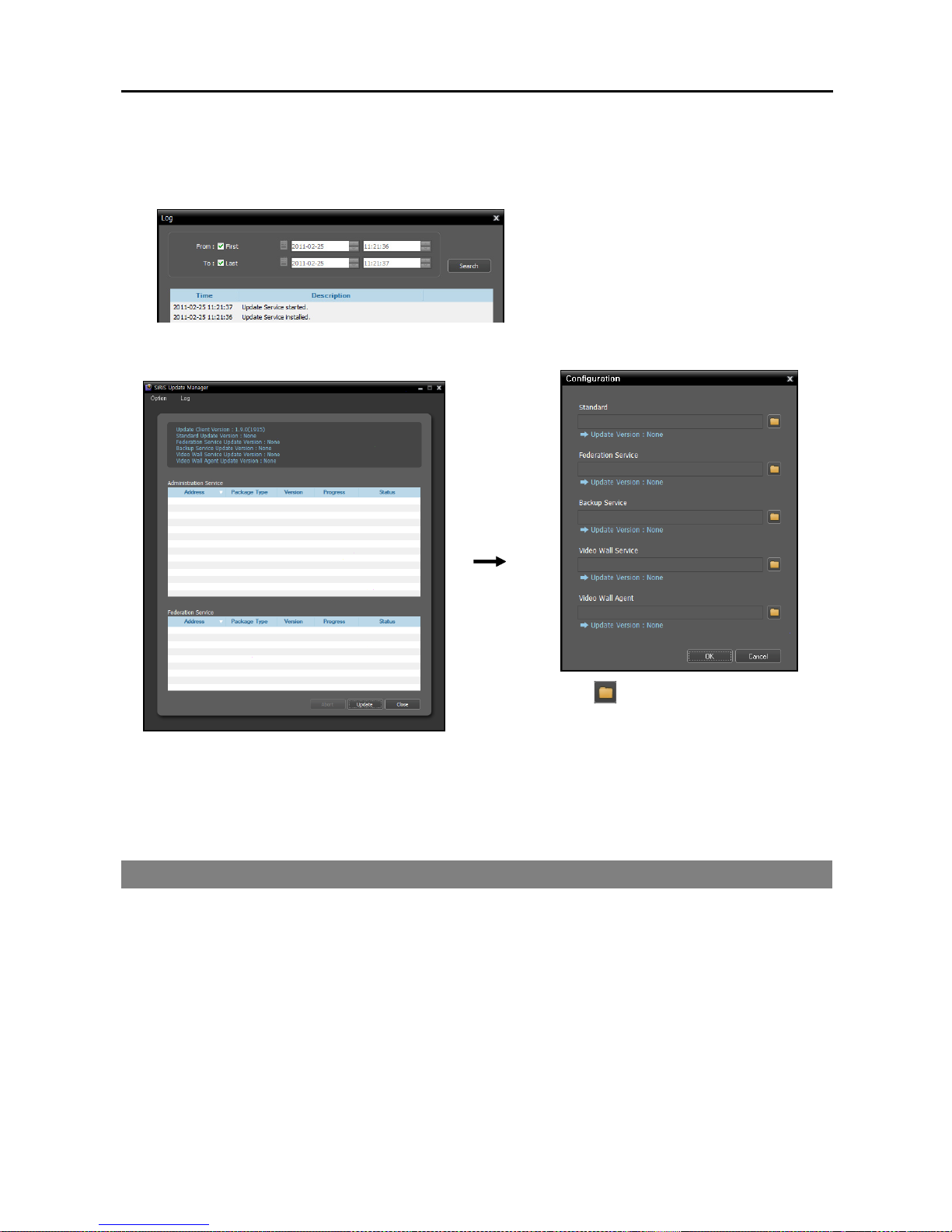
1. Go to the Start Menu in the update server → Click SiRiS → Run the Update Manager program.
Page 15
Network Video Recorder
7
Option: Designates the upgrade file or sets up the port number of the update server.
− Update Package: Designates the folder path of the upgrade installation file.
− Port Setup: Sets the port number of the update server.
Log: Selecting Show Log allows you to check and search the system log.
Setting up the time range of the log and clicking
the Search button displays the log information.
Selecting First displays from the oldest log
entries regardless of date. Selecting Last displays
to the newest log entries regardless of date.
2. Click the Option menu and select Update Package.
Click the button and designate the folder
path of the upgrade installation file. Click the
OK button.
3. Click the Update button at the bottom of the Update Manager screen. For a Client system with no
SiRiS service program installed, clicking the Update button upgrades the Client program. For the NVR
system connects to the update service periodically and automatically upgrades if necessary.
1.6 Tuning On/Off the System
Pressing the power button on the front panel turn on the system and the SiRiS program runs. Clicking
Shutdown under the System menu in the SiRiS Client program or pressing the power button on the front
panel while the system turns on will ask you to confirm turning off the system and the system turns off when
you confirm.
NOTE: Connect a monitor before turning on the system. Video might not be displayed on the monitor when
connecting a monitor after turning on the system.
Page 16

User’s Manual
8
Page 17
Network Video Recorder
9
Chapter 2 — Getting Started
2.1 Connecting
The SiRiS program runs automatically when the NVR system turns on. You are required to log in to the
NVR system as follows.
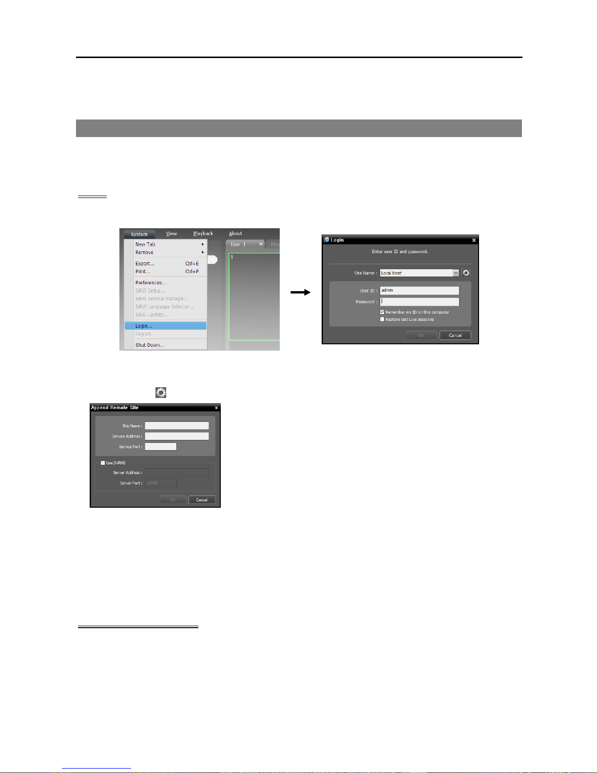
Login
Go to the System Menu at the top left corner of the screen and click Login.
Site Name: Select Local Host to connect to the current NVR system. If you want to connect to another
NVR system, add the NVR system to the list or modify information about the NVR system in the list
by clicking the
button at the right.
− Site Name, Service Address, Service Port: Designate the name
of the NVR system and enter the IP address and port number of the
NVR system (default: 11001). If the NVR system uses the DVRNS
function, check Use DVRNS and enter the IP address (domain
name) and port number of the DVRNS server that the NVR system
is registered. It allows you to enter the name instead of the IP address
of the NVR system when entering Service Address. The name you
enter should be the same as the name registered on the DVRNS
server. Refer to 2.2 System Setting, DVRNS (p. 12) for details
about the DVRNS function.
User ID, Password: Enter your user ID and password. The default user ID is admin and default password
is 12345678. You can change the user ID and password in the User menu. Refer to Chapter 12 —
User Management (p. 111) for details.
Remember my ID on this computer: Check the box if you want to save your ID for logging on.
Restore last Live sessions: Check the box if you want to restore the previous live monitoring sessions
in the current Live panels of the Client program.
Running SiRiS Program
You can run the SiRiS program as follows. Refer to Chapter 3 — System Overview (p. 19) for details
about each program.
Client Program: It runs automatically when the NVR system turns on.
Setup Program: Log in to the NVR system and click SiRiS Setup from the System menu at the top left
corner of the screen.
Page 18
User’s Manual
10
Service Manager Program: Log in to the NVR system and click SiRiS Service Manager from the System
menu at the top left corner of the screen.
2.2 System Setting
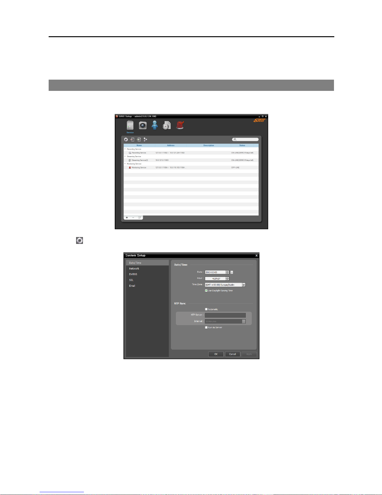
Run the Setup program and set up the NVR system.
Click the
(System Setup) button to display the system setup screen.
Page 19
Network Video Recorder
11
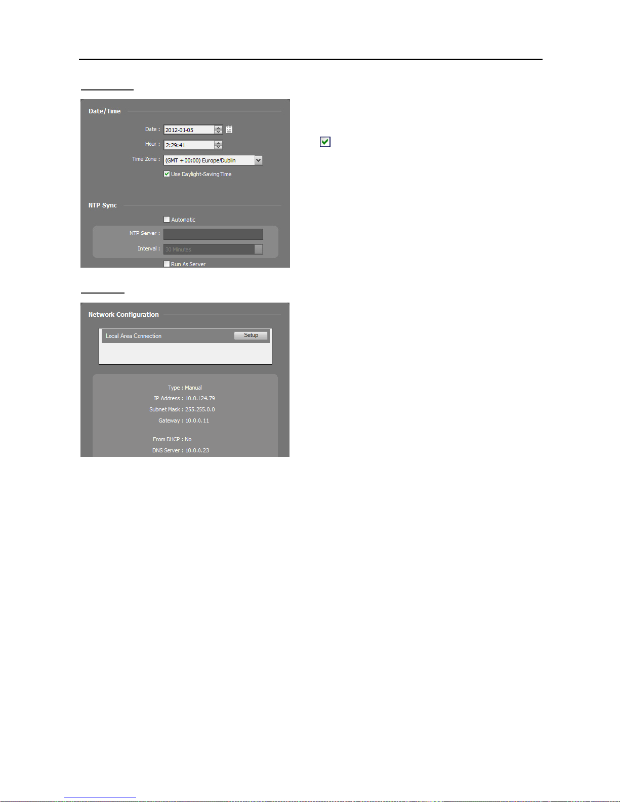
Date/Time
Date, Time, Time Zone: Displays the date, time
and time zone of the NVR system.
NTP Sync
− Automatic Sync: Automatically synchronizes
the time with a time server. Enter the IP address or
the domain name of the time server and set the time
interval for synchronization.
− Run as Server: Check the box to run the NVR
system as a time server.
Network
A list of network cards installed in the NVR system is
displayed. Selecting a network card displays the
network information of the selected network card and
clicking the Setup button allows you to change the
network settings. Ask your network provider for details
about the network connection type and connection
information for the NVR system or the IP address of the
DNS server.
Type: Select the type of NVR system’s network
configuration.
− Set Manually: Select when the system is using a
static IP address for network connection, and set up
LAN parameters manually.
− DHCP: Select when the system is networked via DHCP (Dynamic Host Configuration Protocol). Click
the Apply button, and network information is automatically assigned to the device. If the NVR system
is configured for a DHCP network, it is best to use the DVRNS function because the NVR system’s
IP address might change frequently. See DVRNS below for details about the DVRNS function.
DNS Server: Enter the IP address of the DNS server. If you set up the DNS server, the domain name
of the server can be used instead of the IP address during the DVRNS or time server setup. Ask your
Internet service provider for the IP Address of the DNS Server. When the NVR system is networked
via DHCP, selecting From DHCP automatically assigns the IP address of the DNS server. The assigned
IP address is displayed the next time it is connected.
NOTE: If the NVR system uses a NAT (Network Address Translation) device for network connection, it may
be necessary that you set up port forwarding of all service ports on the NAT device. You can check the
service ports in the Service Manager program (Option menu → Service Option).
Administration service port (default: 11001): You need to do port forwarding for the administration service
port for any of actions behind a NAT device.
Streaming service port (default: 11003):
− When all devices are registered in the streaming service, you do not need to do port forwarding for the
devices.
− When there are devices that are not registered in the streaming service, you need to do port forwarding
for watch ports of each device.
Page 20
User’s Manual
12
Recording service port (default: 11002): You need to do port forwarding for the recording service port to
see recorded data in the NVR system.
Monitoring service port (default: 11004): You need to do port forwarding for the monitoring service port
to receive event information from DVRs and IP products.
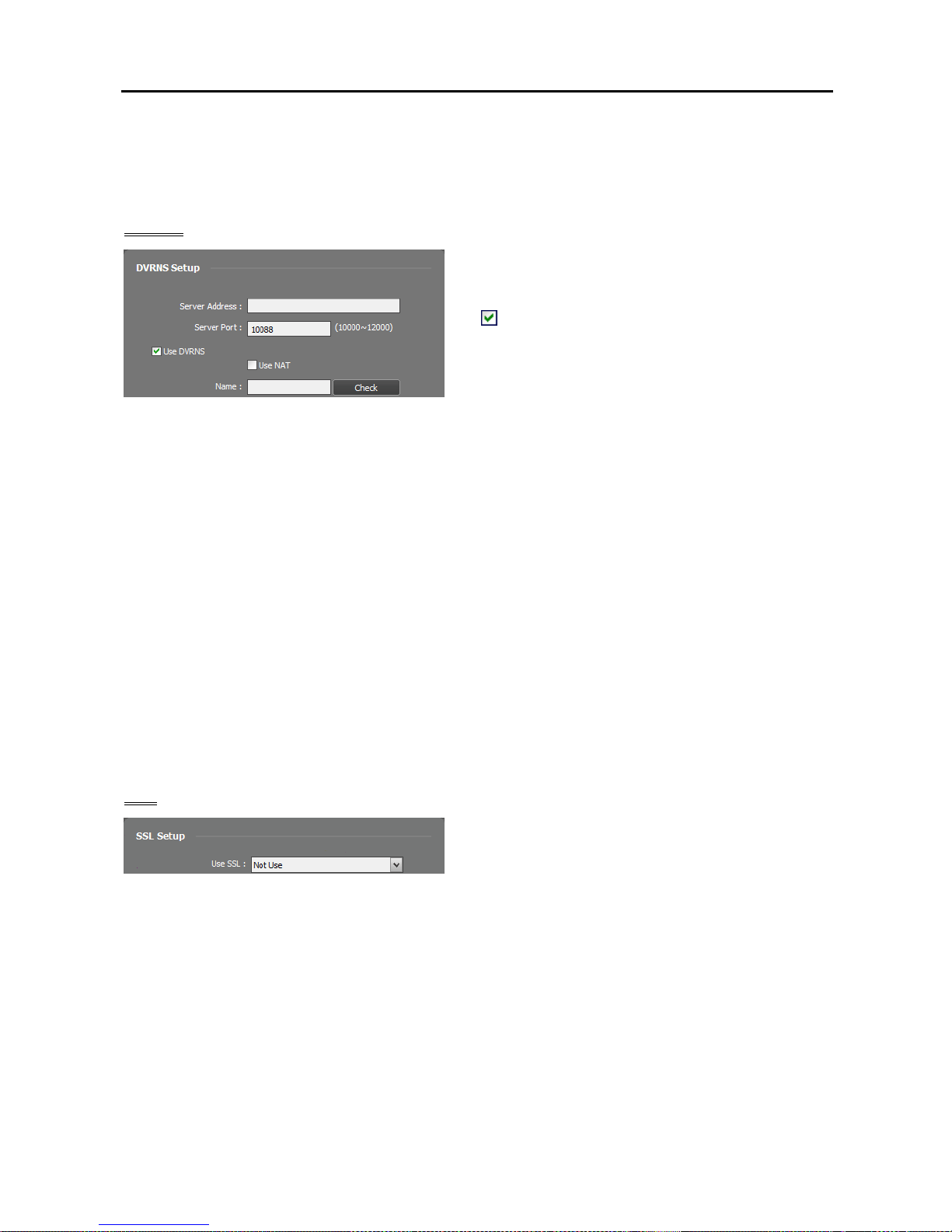
DVRNS
Server Address, Server Port: Enter the IP address
(domain name) and port number of the DVRNS server
to register the NVR system.
Use DVRNS: Allows you to enter the name
instead of the IP address of the NVR system by using
the DVRNS function when connecting to the NVR
system.
− Use NAT: Check the box when the NVR system uses a NAT (Network Address Translation) device
for network connection.
− Name: Enter the NVR system name to be registered on the DVRNS server. Check whether or not
the name is available by clicking the Check button.
NOTES:
The DVRNS (DVR Name Service) function allows the NVR system to use dynamic IP addresses for remote
connection. When using this function, you can access the NVR system remotely by using the NVR system
name instead of its IP address. For the DVRNS function to work properly, the NVR system should be
registered on the DVRNS server.
When LAN settings are changed, set up the DVRNS settings after saving your LAN changes by clicking
the OK button.
You will need to get the IP address or domain name of the DVRNS server from your network administrator.
You can use the domain name instead of IP address if you set up the DNS server during the IP Address
setup.
When using a NAT (Network Address Translation) device, refer to the NAT manufacturer’s instructions
for the proper network settings.
The NVR system name you entered in the Name field should be checked by clicking the Check button,
otherwise the DVRNS changes will not be saved. When entering no name or a name already registered
on the DVRNS server, an error message displays.
SSL
Use SSL: Allows you to enhance the security of data
transferred between services of the SiRiS program
by using the SSL (Secure Sockets Layer) protocol.
Using the SSL function might cause congestion in the
NVR system depending on the security level. Log in
the SiRiS program again after you change the setting.
When the setting is changed, all services that are
currently connected to the administration service
reconnect, and the SiRiS Setup and SiRiS Client
programs are logged out.
Page 21
Network Video Recorder
13
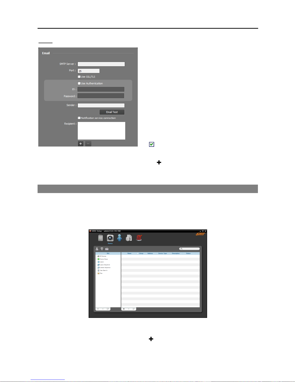
Email
Enter the SMTP server information. The NVR system
can send an email to preset Client users when an event
is detected or to specific recipients when any services
are disconnected from the administration service.
SMTP Server, Port: Enter the email address and port
number of the SMTP server. Select Use SSL/TLS if
the SMTP server requires SSL (Secure Sockets Layer)
authentication.
Use Authentication: Select and enter the ID and
password if the SMTP server requires user
authentication.
Sender: Enter the sender’s email address.
Email Test: Click the button to test if the SMTP server
information is correct.
Notification service connection: Sends an email
to the recipients below when any services are
disconnected from the administration service. Clicking
the
button at the bottom allows you to enter email
addresses of the recipients.
2.3 Registering Devices
You must register devices on the administration service and add the devices to a device group in order to
perform any operation.
Run the SiRiS Setup program.
1. Select the Device menu.
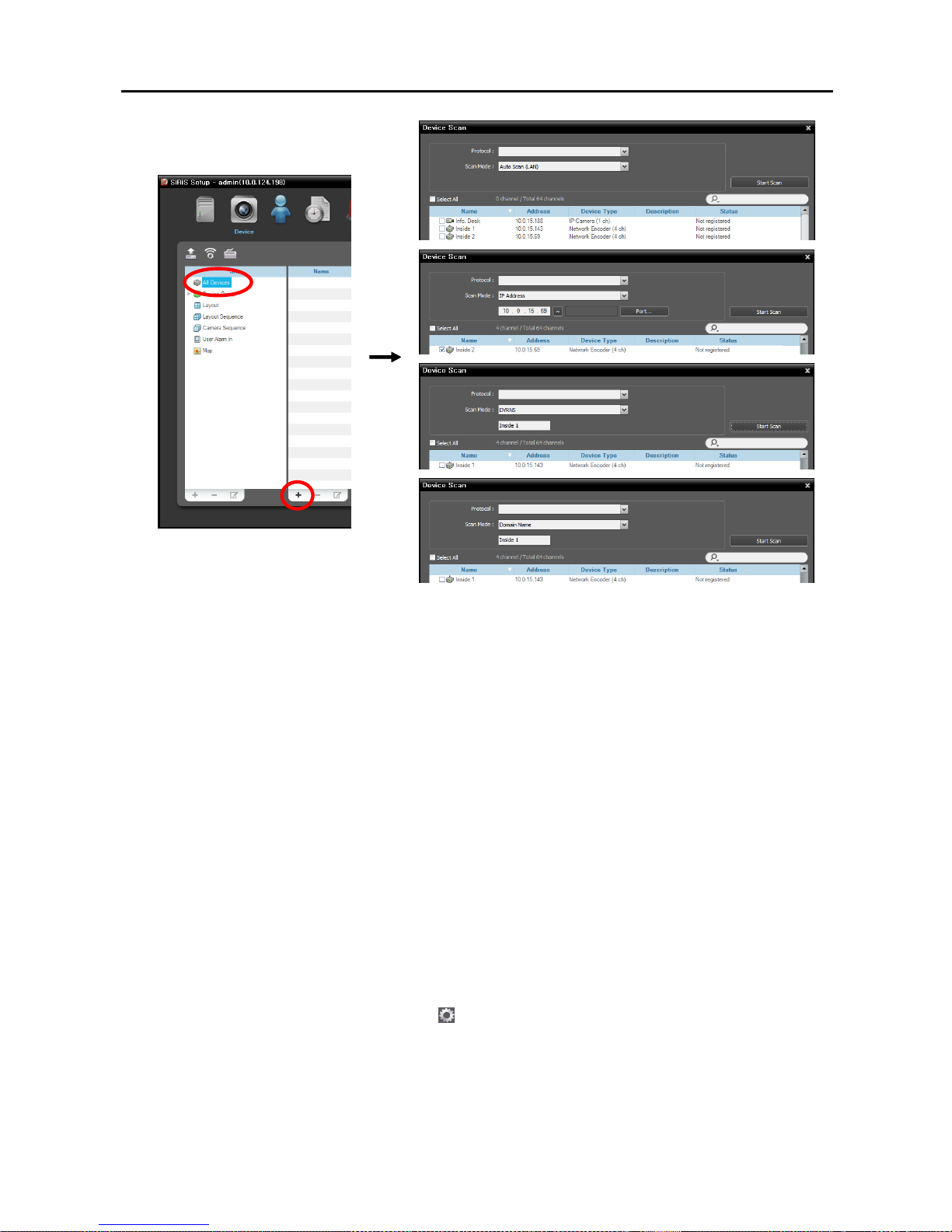
2. Click All Devices in the Site panel, and then the
button at the bottom of the Site List panel. The
Device Scan window appears.
Page 22
User’s Manual
14
Protocol: Select the protocol or manufacturer of the device to scan. Event related functions may not
be supported depending on the protocol that the device uses and device model (supported protocols:
SiRiS protocol, some versions of the Axis/Panasonic WV (DG)/ONVIF
TM
Conformance protocols),
and some other functions may not be supported depending on the settings of the device. Ask your
dealer or distributor for details.
Scan Mode: Select the scan mode. Clicking the Start Scan button displays the results in the list. If
the IP address range of the device is different from that of the NVR system, the SiRiS program considers
the IP address invalid. In this case, you must change the device’s IP address to register the device.
− Auto Scan (LAN): Lists devices in a LAN environment (supported only for the network video devices).
If the device uses the ONVIF
TM
Conformance protocol, this function is supported only when you have
checked the Disable WS-Discovery Windows Service (fdPHost, FDResPub) box during the
software installation in Microsoft
®
Windows® Vista or later operating systems. Also, if the device
uses the ONVIF
TM
Conformance protocol, it is recommended that the device not be networked via
DHCP (Dynamic Host Configuration Protocol). If the device is networked via DHCP, connection
to the device may not be made properly depending on changes in the external network environment.
− IP Address: Allows you to enter the IP address of a device. You can search more than one device
at a time by entering a range of IP addresses. It is recommended that the device not be networked
via DHCP (Dynamic Host Configuration Protocol). If the device is networked via DHCP, connection
to the device may not be made properly depending on changes in the external network environment.
− DVRNS: Allows you to enter the device name registered on a DVRNS server if the device uses the
DVR Name Service (DVRNS) function. Ensure the DVRNS server information on which the device
is registered is correct (Service menu →
(System Setup) button). If the DVRNS server information
is not correct, the device will not be found.
− Domain Name: Allows you to enter the device's domain name registered on a DNS server if the
device uses the Domain Name Service.
− Device Information File: Allows you to import an .xml file which has device connection information
and lists the devices. Ask your dealer or distributor for details about the .xml file.
Page 23
Network Video Recorder
15
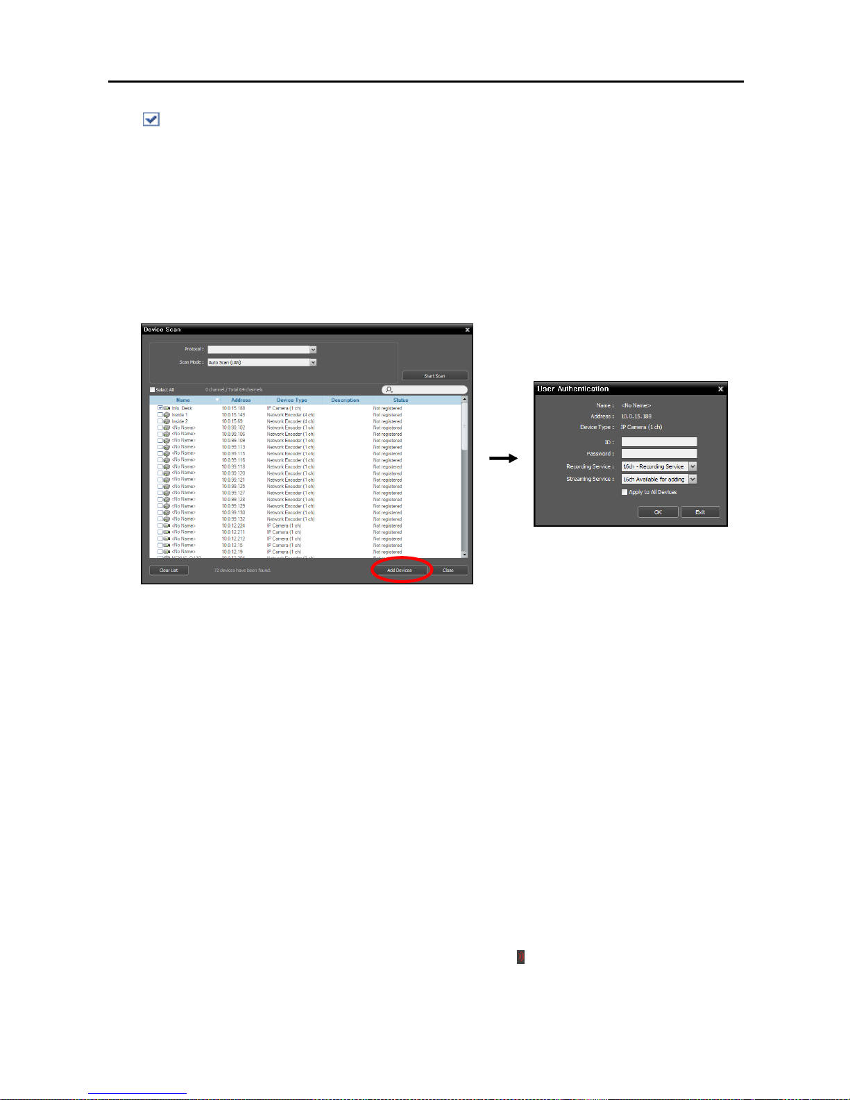
: Select the devices to register by checking the box beside each device name in the list. Selecting
the Select All box selects all devices in the list.
NOTES:
Camera models that are supported will require the selection of the manufacturer protocol (SiRiS protocol
for EVOnet) or the ONVIF
TM
Conformance protocol.
All camera models listed are supported by design and changes to their firmware/protocol/versions are subject
to change without notice and if communication cannot be achieved, please consult the supplier for assistance.
Please refer to the camera’s manufacturer’s manual to enable ONVIF
TM
Conformance protocol, as procedures
may differ for each model. Alternatively ask your supplier about supported models.
3. Click the Add Devices button at the bottom.
Name, Address, Device Type: Displays the name, IP address and type of the selected device. The
name will be updated automatically depending on the settings of the device.
ID, Password: Enter the user ID and password which you set in the device in order to connect to that
device remotely. The connection to the device is allowed only to the users under the Administrator
group of the device, and recording is allowed only to the admin and pacom users under the
Administrator group of the device.
Recording Service: Select a recording service (supported only for the network video devices). The
device is registered on the recording service and the recording service performs recording according
to a recording schedule. The channel number of the recording service indicates the maximum number
of cameras that can be registered, and the name indicates the name of a recording service, which was
set during the Service menu setup. When selecting the Do not record option, the SiRiS program treats
the device during the Schedule setup as though it was not registered and does not perform any of the
scheduled activities associated with the device. If you delete the device from the recording service
after some recording has been done, you cannot search or play back the previously recorded video
though you register the device again. You can check the list of devices registered on the recording
service on a Device Setup tab while setting up the recording service in the Service menu. Refer to
Chapter 13 — Storage Management (p. 113) for details.
Streaming Service: Select whether or not to use the streaming service for monitoring video from the
device. If the device uses the streaming service, the SiRiS program transmits video from the device
to the client system through the streaming service, and it allows multiple users to monitor video
simultaneously. When the device uses the streaming service,
icon is displayed beside the device
in the Site List of the SiRiS Client program. The number of channels that can be streamed equals
the number of channels that can be recorded. Refer to Chapter 10 — Streaming (p. 91) for details.
Page 24
User’s Manual
16
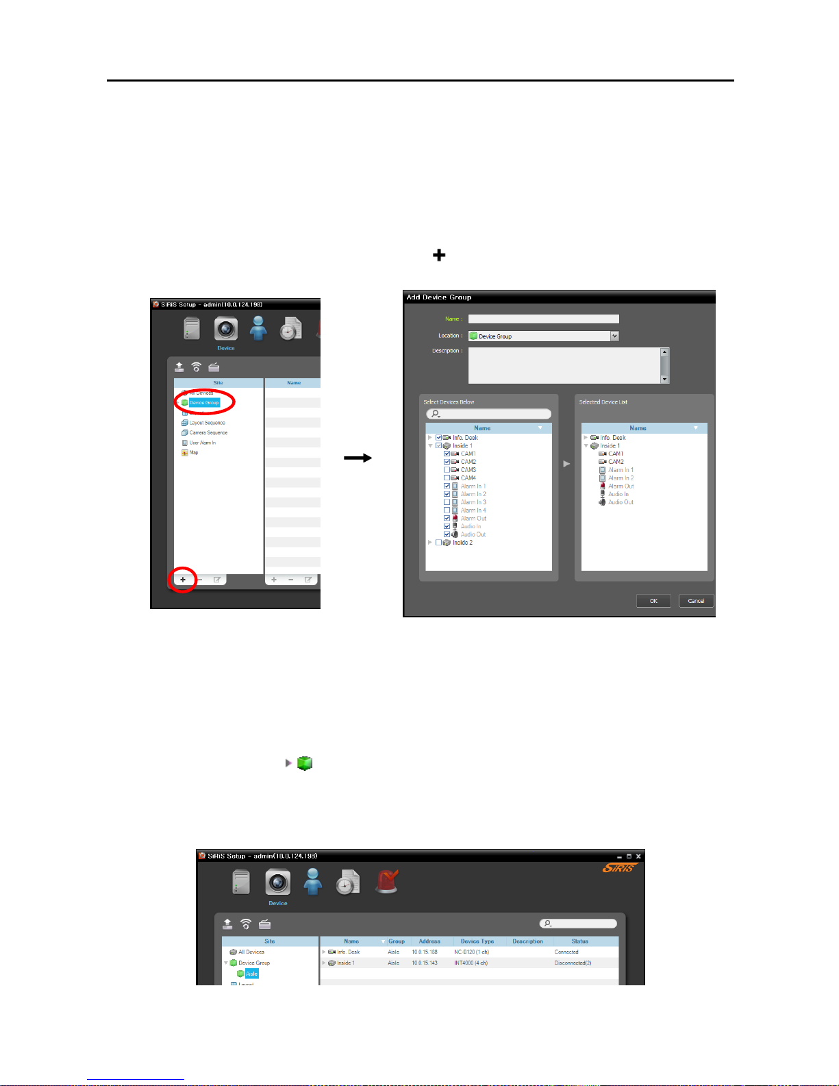
Apply to All Devices: Select to apply the same user ID and password to all selected devices if you
selected more than one device and the selected devises have the same user ID and password.
NOTES:
If the device is a DVR, it might be necessary to enter the DVR port numbers depending on the specifications
and version of the DVR.
When registering a four-channel network video transmitter which uses the SiRiS protocol, all four
cameras are automatically registered even if some of the four cameras are disabled.
4. Click Device Group in the Site panel, and then the
button at the bottom of the Site panel. The Add
Device Group window appears.
Name: Enter the device group name.
Location: Select an upper group to which the device group will belong.
Select Devices Below, Selected Device List: Check the box beside cameras in the left panel, and
the selected cameras are added to the right panel.
Clicking the OK button completes the device group registration.
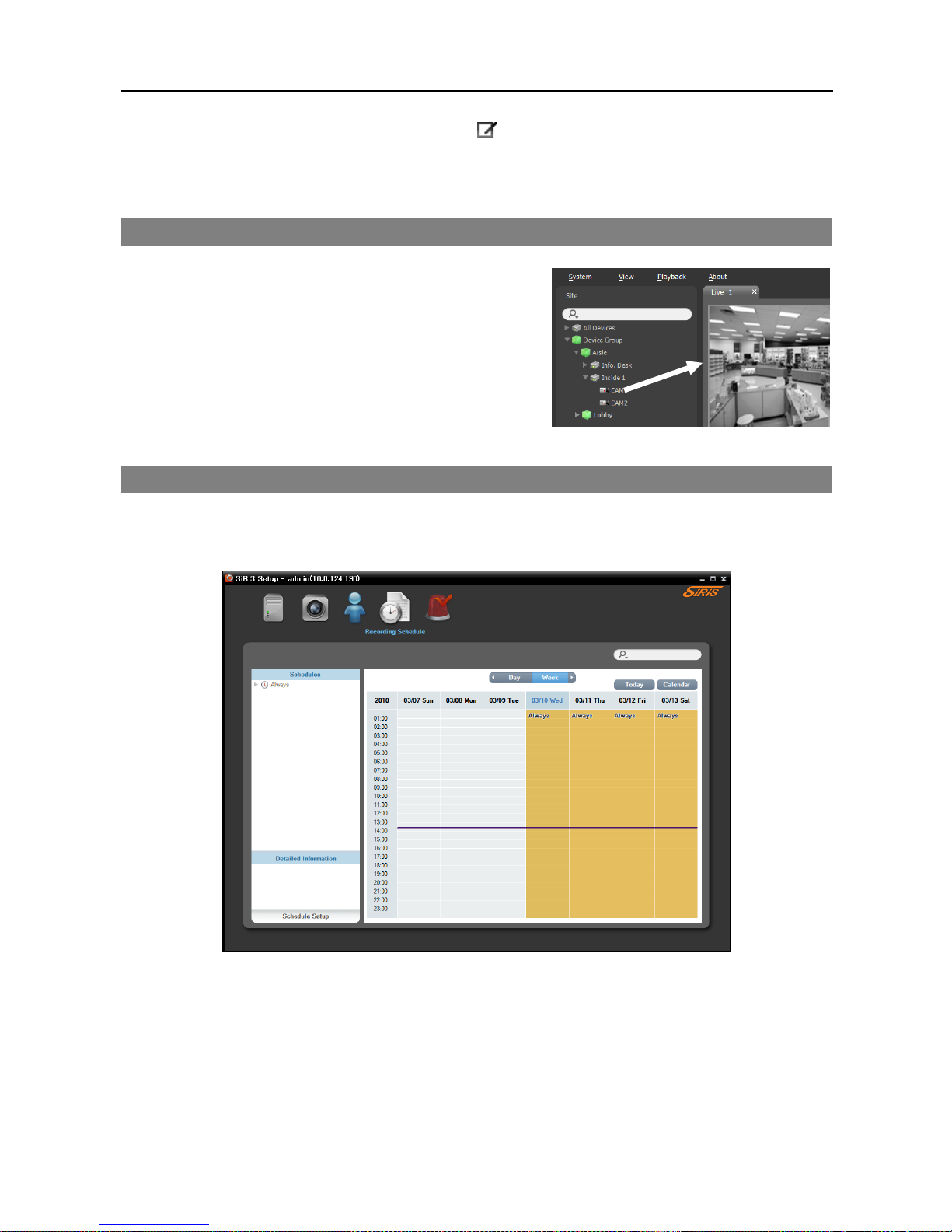
5. Check that the device was added to the device group correctly. Click Device Group in the Site panel
and then the arrow button (
) beside Device Group. Clicking the registered group displays the list
of devices added to the device group and connection status in the Site List panel. If the connection was not
made properly, the network disconnection log is displayed (only for devices registered on the recording
service). Refer to Appendix – Network Disconnection Log (p. 143) for details about the network
disconnection log.
Page 25
Network Video Recorder
17
Selecting the registered device group, and then the button at the bottom of the Site List panel displays
the Edit Device Group window and allows you to edit the selected device group. Refer to Chapter 11
— Device Management (p. 93) for details.
2.4 Live Video Monitoring
1. Check that the devices were added to a device group in the
Site list.
2. Click the Live tab on the tab panel → Select a site to connect
to from the Site list, and drag and drop it on the Live screen.
Live video from the selected site is displayed on the screen.
Refer to Chapter 4 — Live Video Monitoring (p. 41) for
details.
2.5 Recording
Run the Setup program. Select the Recording Schedule menu and set up the recording schedule following
the procedures below. Refer to 5.1 Setting up Recording Schedule (p. 57) for details.
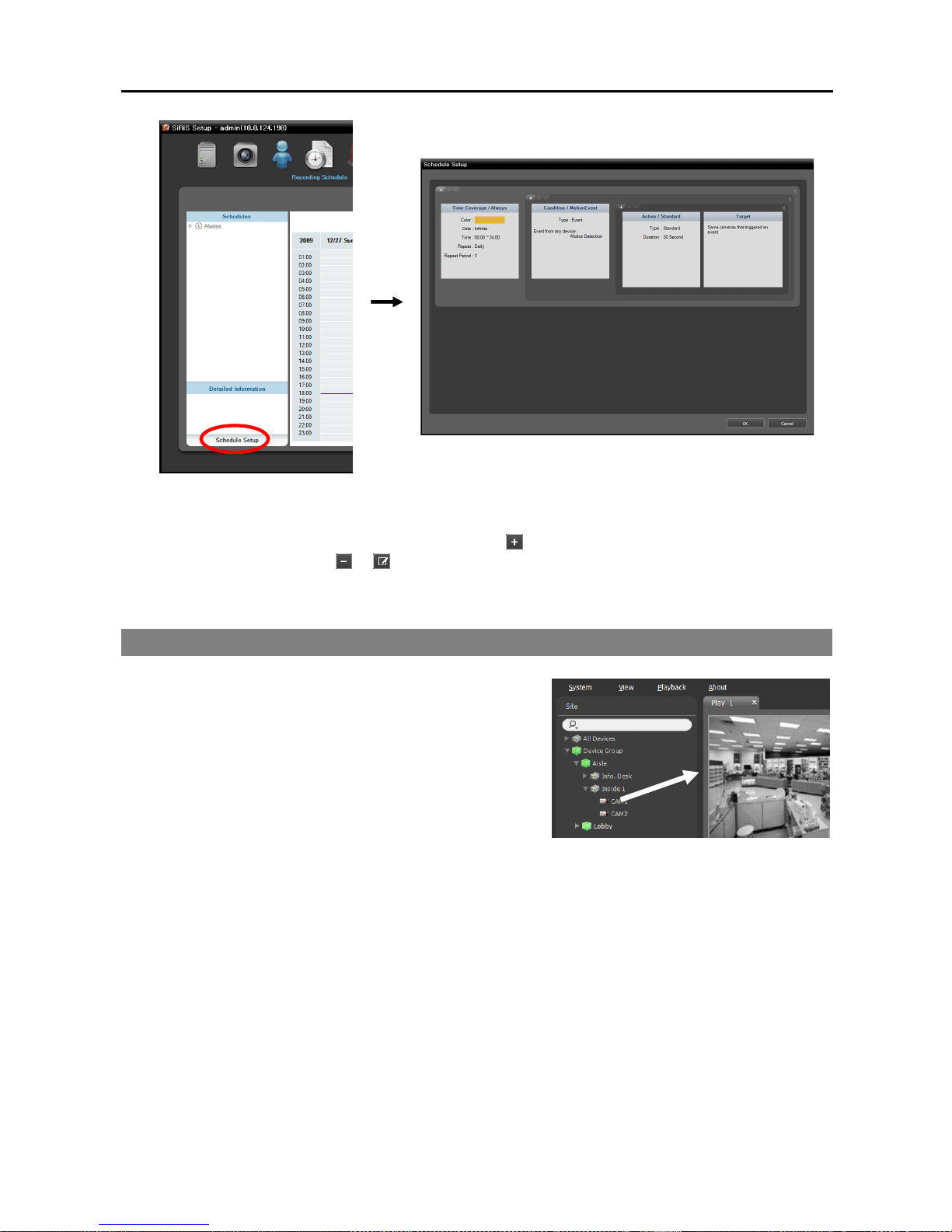
1. Click the Schedule Setup button at the bottom. The Schedule Setup window appears, and schedule
windows are displayed with the current settings for each Preset.
Page 26
User’s Manual
18
2. Double click anywhere in the empty space of each schedule window, and the Preset setup window appears.
3. Select a desired Preset from the Preset list, or click the
button to add a new Preset. Selecting a Preset
from the list and clicking the
or button deletes the selected Preset or allows you to edit the selected
Preset settings. Clicking the OK button applies the settings.
2.6 Playing Recorded Video
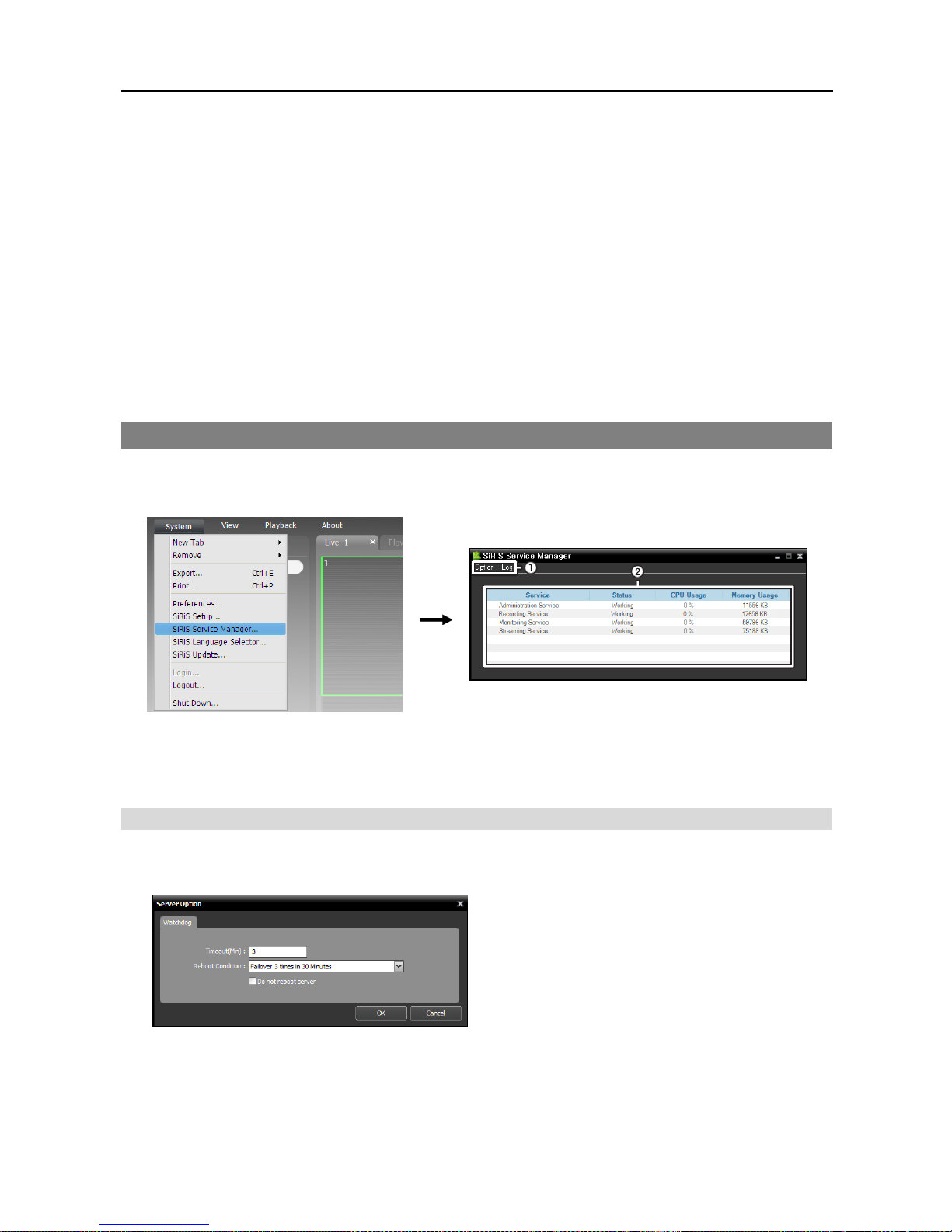
1. Check that the devices were added to a device group in the
Site list.
2. Click the Play or DVR Search tab on the tab panel → Select
a site to connect to from the Site list and drag and drop it
on the Play or DVR Search screen. Recorded video from
the selected site is displayed on the screen. Refer to
Chapter 6 — Recorded Video Playback & Exportation
(p. 69) for details.
Page 27
Network Video Recorder
19
Chapter 3 — System Overview
The NVR system consists of the following programs:
SiRiS Service Manager: Controls the operation of services or displays system log. Refer to 3.1 Service
Manager (p. 19) for details.
SiRiS Setup: Allows you to add service, devices and users, or set up recording schedules, event management
schedules and storage. Refer to 3.2 Setup (p. 24) for details.
SiRiS Client: Allows you to monitor video from registered cameras, play back recorded video from
storage, export recorded video and check the system log and devices’ status. Refer to 3.3 Client (p. 29)
for details. You can install and run the SiRiS Client program on a PC. Refer to Chapter 17 — Remote
Monitoring (p. 137) for details about installing the SiRiS Client program.
3.1 Service Manager
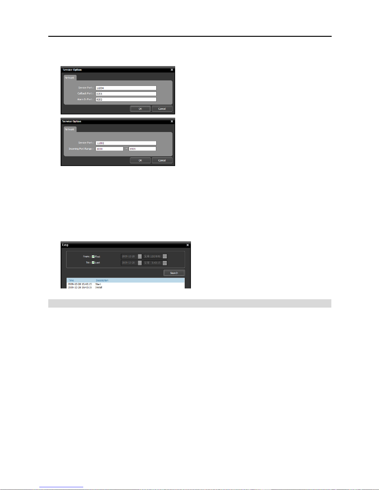
Log in to the NVR system. Refer to 2.1 Connecting, Login (p. 9) for details about the login. Go to the
System Menu → Click SiRiS Service Manager → Run the SiRiS Service Manager program.
① Menu: Allows you to control the operation of the services or display the system log.
② Status Display: Displays the status of services.
Menu
Option
− Server Option: You can change the Watchdog setting.
Timeout (Min.): Set up the waiting time to restart
services when services fail to operate. The service
checks the system status. When the services fail to
operate during the designated waiting time, the system
restarts services automatically.
Reboot Condition: Set up the reboot condition when
services fail to operate. Checking the Do Not Reboot
Server option allows the system to restart services
without rebooting.
NOTE: “Watchdog” in the SiRiS program is a function that periodically checks the operation of the current
server and restarts services automatically when services fail to operate during the predefined time.
Page 28
User’s Manual
20
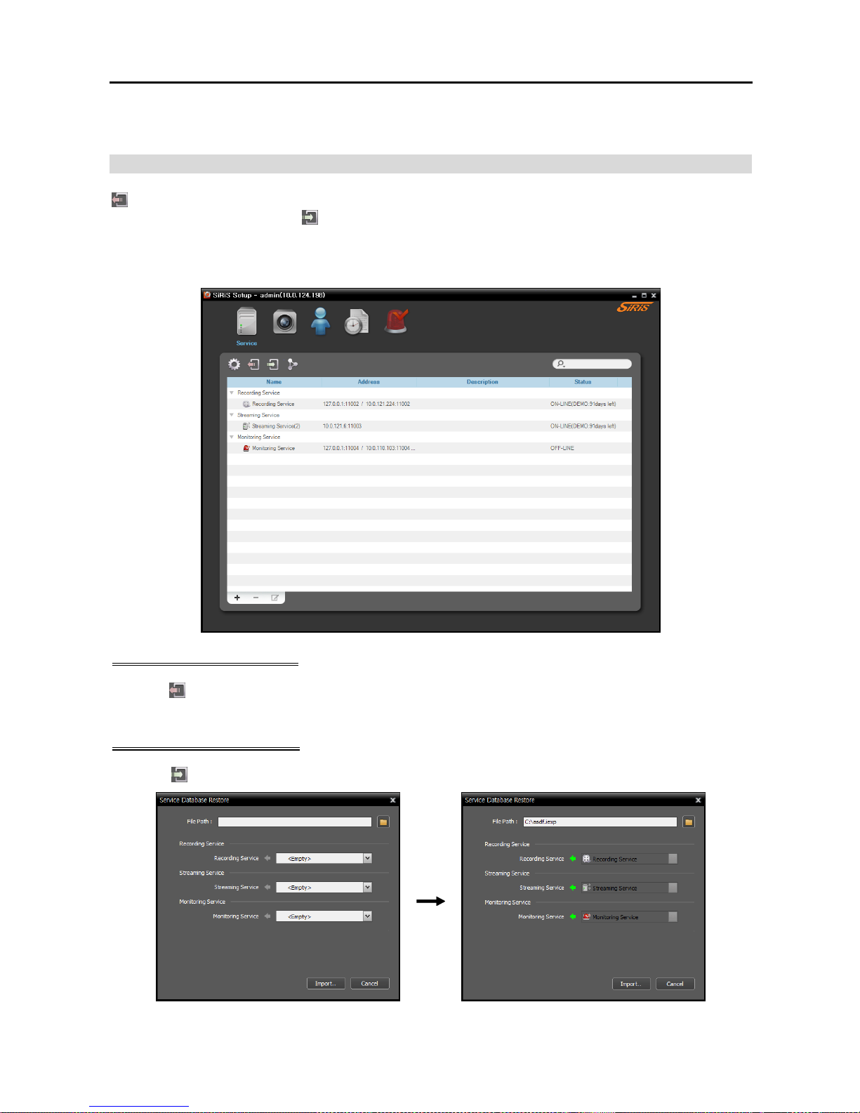
− Service Option: Selecting a service from the service list and Service Option allows you to set up
the information for connection to the selected service.
Service Port: Enter the port number for connection to
the selected service.
Callback Port: Enter the port number to receive a
callback message from the device (supported only for the
monitoring service). The port number you enter should
match the port number set on the device for remote
callback.
Alarm In Port: Set up the port number to receive text
strings for user alarm in event detection (supported only
for the monitoring service). Refer to Chapter 11 —
Device Management, User Alarm In Event Setup
(p. 94) for details about the user alarm in event.
RTP Incoming Port Range: Enter the port range if a
device which transmits images using the RTP protocol
is registered (supported only for recording or streaming
services). Port range settings must be changed if the
network firewall or local network allows only specific
UDP/RTP port numbers. The port numbers should not
conflict with the RTP port numbers of Client system or
port numbers of other streaming programs. If an RTP
port number conflicts with others, recording and streaming
may not be available.
Log: Selecting Show Log allows you to check and search the system log.
Setting up the time range of the log and clicking
the Search button displays the log information.
Selecting First displays from the oldest log entries
regardless of date. Selecting Last displays to the
newest log entries regardless of date.
Status Display
Service: Displays the list of services supported by the NVR system.
− Administration Service: Manages information of services, devices, users and schedules for operating
the SiRiS program. When the administration service is not working, the SiRiS program does not work.
− Recording Service: Records video transmitted from the network video device. When the recording
service is not working, the SiRiS program does work but the system will not record and playback of
previously recorded video will not be available.
− Monitoring Service: Notifies live events and callback events detected at the device registered in the
NVR system to the Client system.
− Streaming Service: Streams images from devices to multiple client systems simultaneously.
Status: Displays the working status of each service.
− Working: Indicates the service is working properly. You can operate the SiRiS Setup and SiRiS
Client program, and the system performs recording based on the recording schedule.
− Failed: Indicates the service failed to run because of an unknown problem. The system restarts the
services or reboots the system based on the Watchdog settings. Refer to Menu (p. 19) for details about
Watchdog settings.
CPU Usage: Displays the CPU usage of each service.
Page 29
Network Video Recorder
21
Memory Usage: Displays the memory usage of each service.
Service Database Backup/Restore
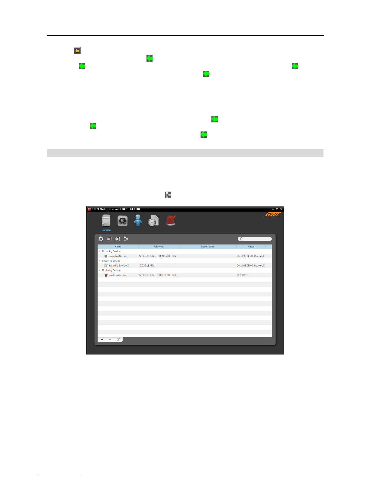
(Service Database Backup) button allows you to save the setting values related to services as an .iexp
file in the USB storage device.
(Service Database Restore) button allows you to apply the saved setting
values to the current NVR system.
Run the SiRiS Setup program.
Service Database Backup
Click the (Service Database Backup) button → Enter the name of the setup file to save the current setting
values → When saving is complete, the list of Services is displayed.
Service Database Restore
Click the (Service Database Restore) button.
Page 30
User’s Manual
22
Click the button at the top right corner and select a setup file to apply → Services of the current NVR
system are displayed to the left of the
icon. Services that are saved in the setup file are displayed to the
right of the icon. Select the service to apply from the drop-down menu to the right of the icon. If
there is only one service for a service type to the left of the
icon or the services in the setup file are the
services that were backed up from the current NVR system, the services in the setup file will be applied
automatically → Click the Import button at the bottom → The SiRiS Setup program restarts after applying
is complete.
NOTE: This is not supported in the following cases:
– When the software version of the services to the right of the
icon is later than that of the services to
the left of the
icon.
– When the type of the services to the left and right of the icon differs.
Cascade
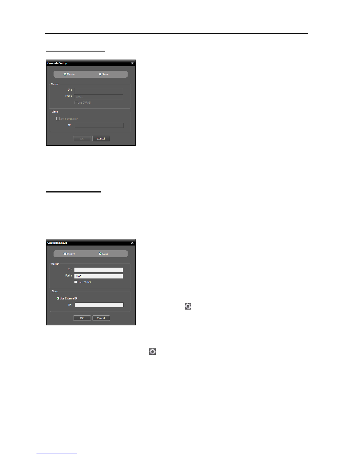
If you use more than one NVR system, you can run the NVR systems as a master or slave systems. It allows
you to watch video from all devices registered on the master and slave NVR systems and search all video
recorded in the master and slave NVR systems in the master NVR system.
Run the SiRiS Setup program → Click the (Cascade) button.
Page 31
Network Video Recorder
23
Master NVR System
Master, Slave: Select Master. It allows you to watch or search
video of this NVR system and slave NVR systems (maximum
7) registered on this NVR system. The NVR system runs as a
master NVR system by default and this setting will be used when
the NVR system has been run as a slave NVR system and you
want to change it back to a master NVR system.
1. Click the OK button in the bottom.
2. Enter the ID and password of the master NVR system.
3. The recording and streaming services of this NVR system, which
have been registered on the master NVR system, are restored to
this NVR system. When the recording and streaming services
are restored, devices which are not registered on the recording
service are deleted and device related settings such as device
groups and usage of the streaming service for monitoring video
from a device, etc. are all reset and you have to check all the
settings and set up again.
Slave NVR System
NOTE: When you change back the NVR system which has been run as a slave NVR system to a master
NVR system,
devices which are not registered on the recording service are deleted and device related settings
such as device groups and usage of the streaming service for monitoring video from a device, etc. are all
reset and you have to check all settings and set up again. If necessary, write down the current device related
settings and save it in a separate place before setting the slave NVR system.
Master, Slave: Select Slave. This NVR system is registered
on the master NVR system and it allows you to watch or search
video of this NVR system in the master NVR system.
− Master: Enter the IP address and port number of the master
NVR system. If the master NVR system uses the DVRNS
function, selecting Use DVRNS allows you to enter the master
NVR system’s name registered on the DVRNS server instead
of the IP address. You can check the name in the master NVR
system’s DVRNS setting (connect to the master NVR system
→ click the
(System Setup) button in the Service menu of
the SiRiS Setup program → click DVRNS).
− Slave: If this NVR system uses the DVRNS function, no settings are required. If this NVR system
does not use the DVRNS function, enter the external IP address of this NVR system. If the external
IP address is not correct, you may not watch or search video. If you want, you can change the DVRNS
settings of this NVR system (click the
(System Setup) button in the Service menu → click DVRNS).
1. Click the OK button in the bottom.
2. Enter the ID and password of the master NVR system.
3. The recording and streaming services of this NVR system are registered on the master NVR system.
The devices registered on the recording service are registered together.
4. This NVR system reboots.
Page 32
User’s Manual
24
3.2 Setup
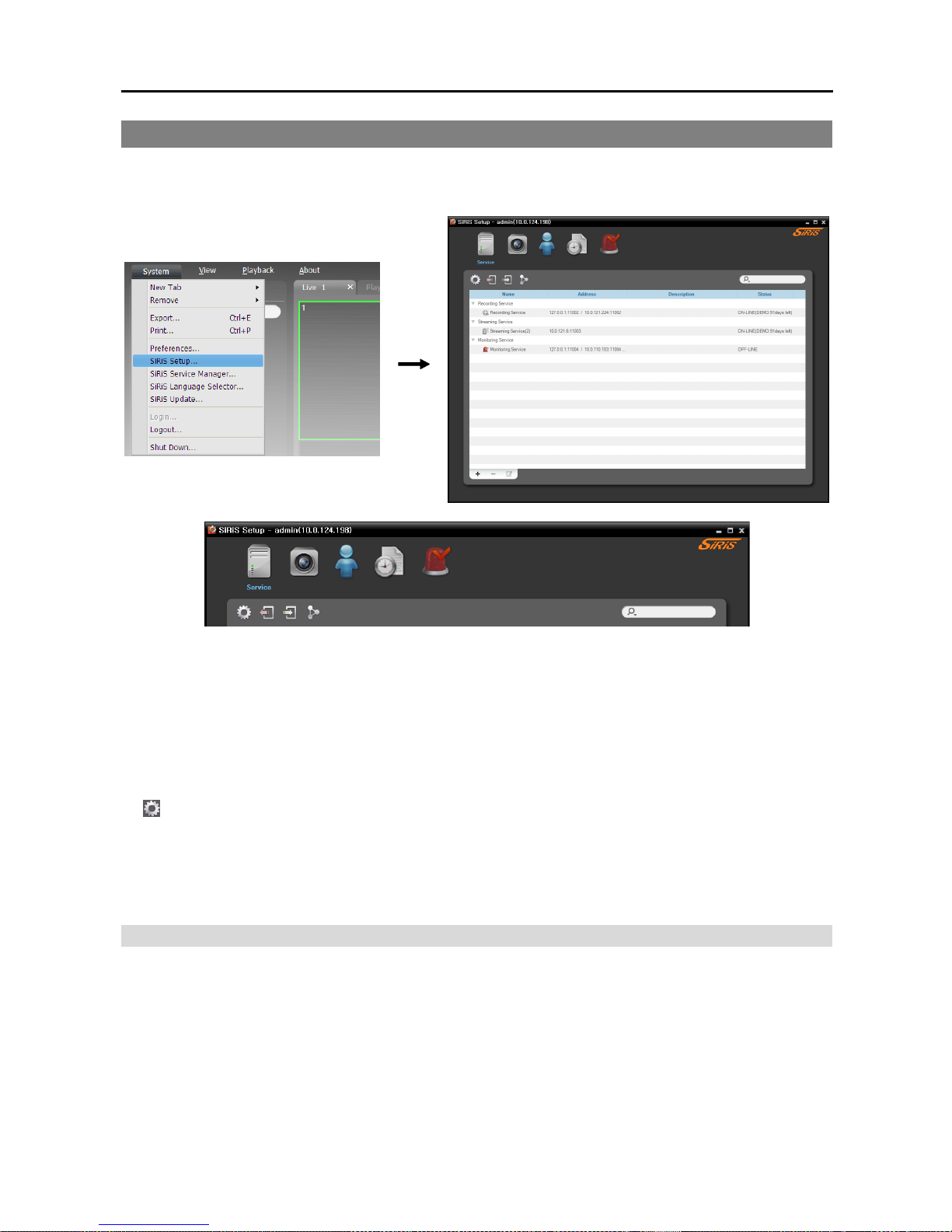
Log in to the NVR system. Refer to 2.1 Connecting, Login (p. 9) for details about the login. Go to the
System Menu → Click SiRiS Setup → Run the SiRiS Setup program.
Service: Allows you to register and manage services and storage. Refer to Service (p. 24) for details.
Device: Allows you to register and manage sites. Refer to Device (p. 25) for details.
User: Allows you to register and manage users or user groups. Refer to User (p. 27) for details.
Recording Schedule: Allows you to set up recording schedules. Refer to Recording Schedule (p. 27)
for details.
Event Management: Allows you to set up event management schedules. Refer to Event Management
(p. 28) for details.
(System Setup): Sets up the NVR system. Refer to 2.2 System Setting (p. 10) for details.
NOTE: An alert message is displayed at the bottom of the SiRiS Setup screen in the following cases:
– No storage is allocated to a recording service.
– Storage for recording is full.
Service
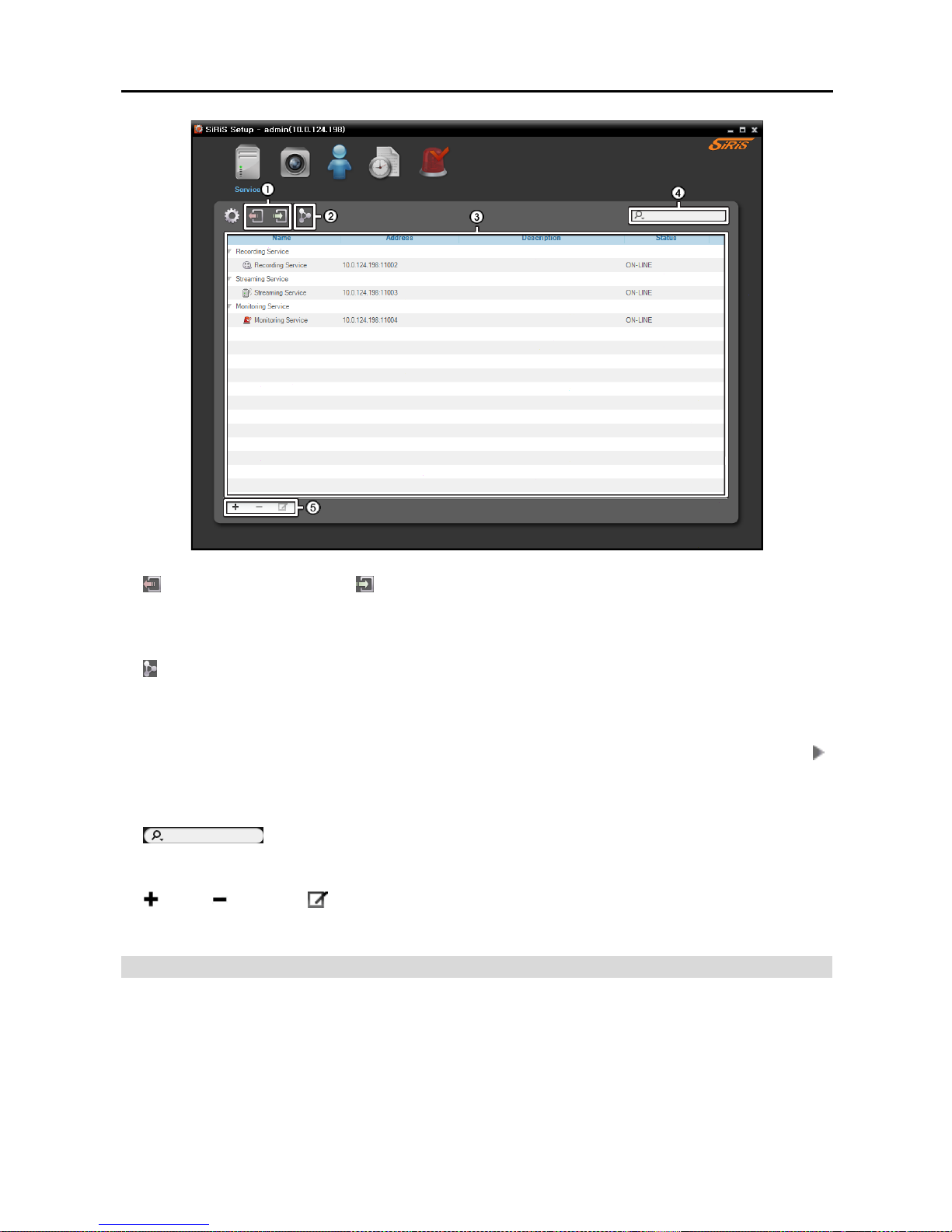
The Service menu allows you to register and manage services and storage.
Page 33
Network Video Recorder
25
①
(Service Database Backup), (Service Database Restore): It allows you to save the setting values
related to services as an .iexp file in the USB storage device. It also, allows you to apply the saved setting
values to the current NVR system. Refer to 3.1 Service Manager, Service Database Backup/Restore
(p. 21) for details.
②
(Cascade): If you use more than one NVR system, you can run the NVR systems as a master or slave
systems. It allows you to watch video from all devices registered on the master and slave NVR systems
and search all video recorded in the master and slave NVR systems in the master NVR system. Refer
to 3.1 Service Manager, Cascade (p. 22) for details.
③ Service List: Displays list of services supported in the SiRiS program. Clicking the arrow button (
)
beside each service displays the list and information about services registered in the SiRiS program.
− Address: Displays the IP address and port number.
− Status: Displays the connection status.
④
(Incremental Search): Allows you to search for a service registered in the NVR system.
Entering text that you want to search for causes the search results to be displayed. Search results are
displayed immediately as matching text is found. As you enter more text, the results narrow.
⑤
(Add), (Remove), (Edit): Allow you to add, remove and edit a service and storage. Refer
to Chapter 13 — Storage Management (p. 113) for details about adding storage for a recording.
Device
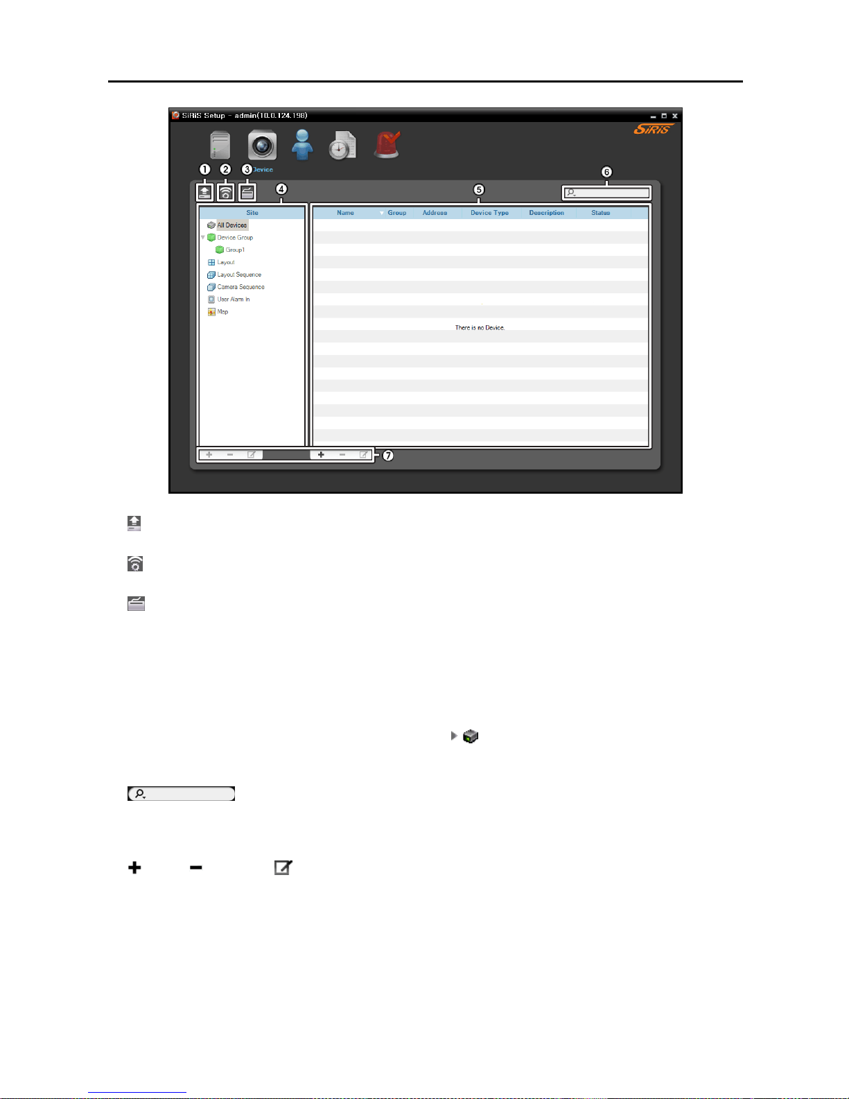
The Device menu allows you to register and manage sites.
Page 34
User’s Manual
26
①
(Multiple Firmware Upgrade): Allows you to upgrade software for several devices at the same time.
Refer to 11.2 Managing Devices, Upgrading Device’s Software (p. 103) for details.
②
(Multiple Remote Setup): Allows you to change settings of several devices at the same time using a
setup file. Refer to 11.2 Managing Devices, Changing Device’s Setting Remotely (p. 102) for details.
③
(Network Keyboard Setup): Allows you to add, remove and edit a network keyboard. You can control
the Client program with a network keyboard. Refer to Chapter 16 — Controlling With a Network
Keyboard (p. 131) for details.
④ Site Panel: Displays site group lists supported by the SiRiS program.
⑤ Site List Panel: Displays the list and information about sites registered in each group. If the connection
was not made properly, the network disconnection log is displayed (only for devices registered on the
recording service). Refer to Appendix – Network Disconnection Log (p. 143) for details about the
network disconnection log. Clicking the arrow button (
) beside each device name displays the status
of video in, alarm in/out and audio in/out supported by the device (Record: During Time-Lapse recording
or Event-Based recording, Panic: During Instant recording, Idle: Ready to record).
⑥
(Incremental Search): Allows you to search for a device or site registered in each group.
Selecting a group in the Site panel and entering text that you want to search for causes the search results
to be displayed. Search results are displayed immediately as matching text is found within the selected
group. As you enter more text, the results narrow.
⑦
(Add), (Remove), (Edit): Allow you to add, remove and edit a device or a site. You can also
delete sites from the group or to edit registration information by using the menu that is displayed when
selecting a site and clicking the right mouse button. If you select a device, you can connect to it and
change its settings or upgrade its software remotely. If you delete a device from All Devices and register
the device again, the NVR system considers the device as a new device (network video devices only).
Refer to Chapter 11 — Device Management (p. 93) for details about registering a device or device
group, or Chapter 4 — Live Video Monitoring (p. 41) for details about registering a layout or sequence.
Page 35
Network Video Recorder
27
NOTE: In this document, a “site” refers to a device group, layout or sequence registered on the administration
service.
User
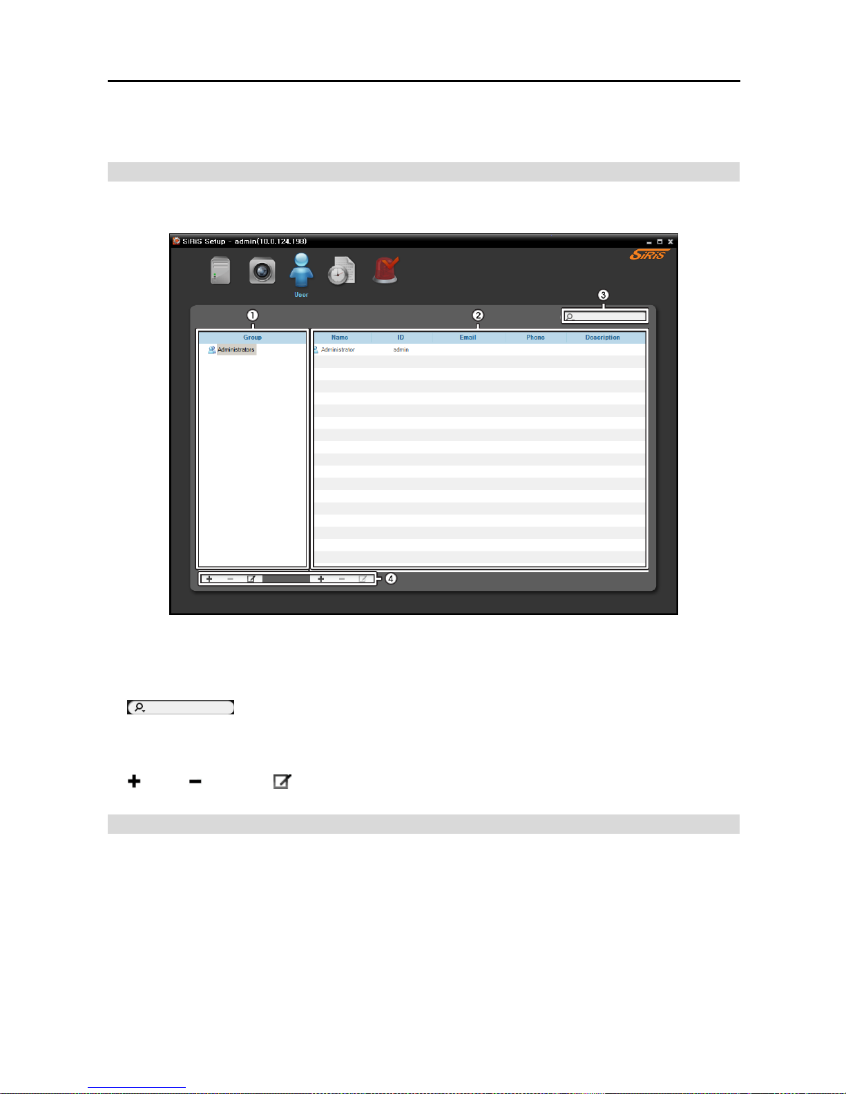
The User menu allows you to register and manage users or user groups.
① Group Panel: Displays a user group list. The Administrators group has authority to perform all functions,
and the authority settings cannot be edited.
② User List Panel: Displays the list and information about users registered in each group.
③
(Incremental Search): Allows you to search for a user registered in each group. Selecting
a group in the Group Panel and entering text that you want to search for causes the search results to be
displayed. Search results are displayed immediately as matching text is found within the selected group.
As you enter more text, the results narrow.
④
(Add), (Remove), (Edit): Allow you to add, remove and edit a user group or user.
Recording Schedule
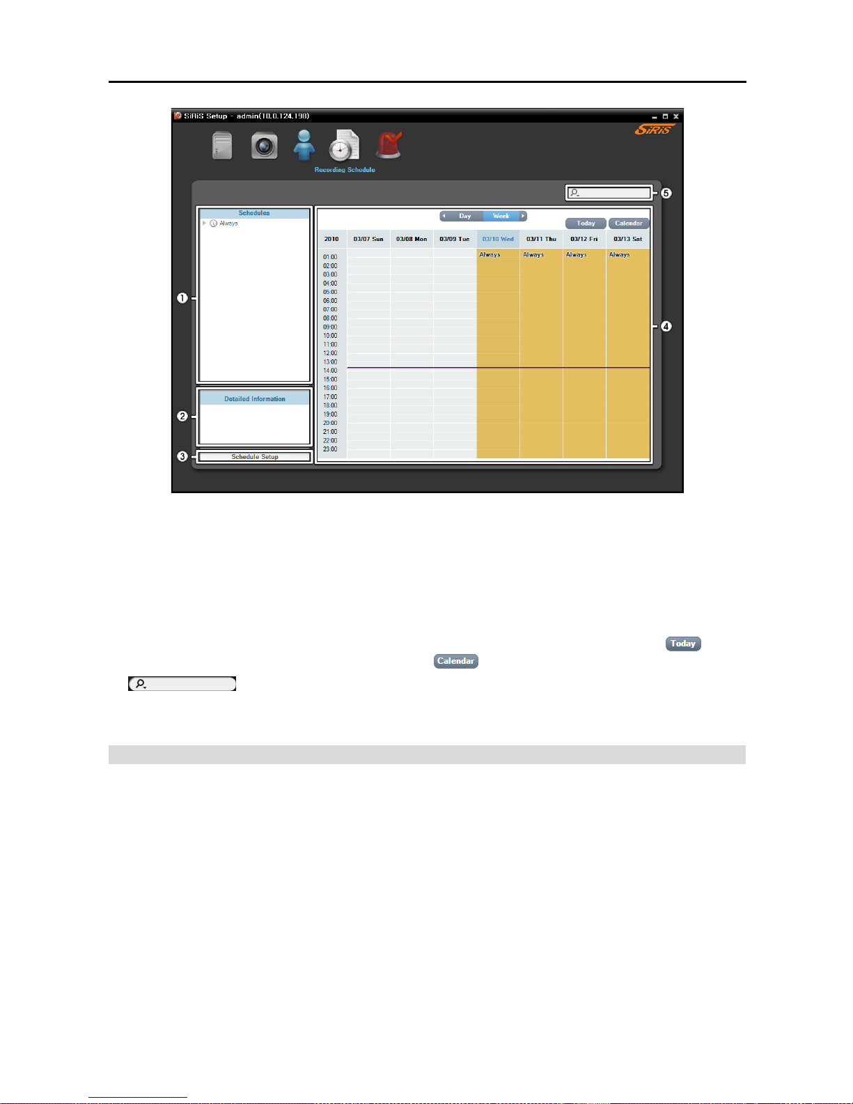
The Recording Schedule menu allows you to set up the schedule for recording.
Page 36
User’s Manual
28
① Schedule Panel: Displays a registered schedule list. The NVR system performs recording based on
the schedule.
② Detailed Information Panel: Displays setting values of the selected recording schedule.
③ Schedule Setup: Allows you to register recording schedules for Time-Lapse Recording or Event-Based
Recording or to set up recording settings for Instant Recording. Refer to 5.1 Setting up Recording
Schedule (p. 57) for details.
④ Schedule Table: Displays the current recording schedule by day or week. Clicking the
button
displays the today’s recording table. Clicking the
button displays a calendar.
⑤
(Incremental Search): Allows you to search for a registered schedule. Entering text
that you want to search for causes the search results to be displayed. Search results are displayed immediately
as matching text is found within the registered schedule. As you enter more text, the results narrow.
Event Management
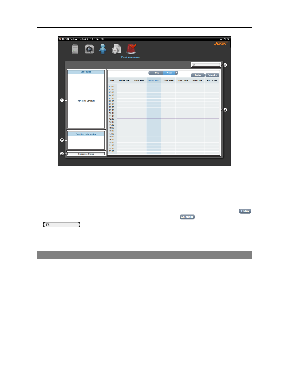
The Event Management menu allows you to set up event management schedules.
Page 37
Network Video Recorder
29
① Schedule Panel: Displays a registered schedule list. The NVR system manages events based on the
schedule.
② Detailed Information Panel: Displays setting values of the selected event management schedule.
③ Schedule Setup: Allows you to register event management schedules. Refer to 14.1 Setting up
Event Management Schedule (p. 115) for details.
④ Schedule Table: Displays the current event management schedule by day or week. Clicking the
button displays the today’s event management table. Clicking the button displays a calendar.
⑤
(Incremental Search): Allows you to search for a registered schedule. Entering text
that you want to search for causes the search results to be displayed. Search results are displayed immediately
as matching text is found within the registered schedule. As you enter more text, the results narrow.
3.3 Client
The SiRiS Client program runs automatically when the system turns on. You can also run the SiRiS Client
program remotely by running the Client program installation file in the enclosed software CD. Refer to
Chapter 17 — Remote Monitoring (p. 137) for details about running the SiRiS Client program remotely.
Page 38
User’s Manual
30
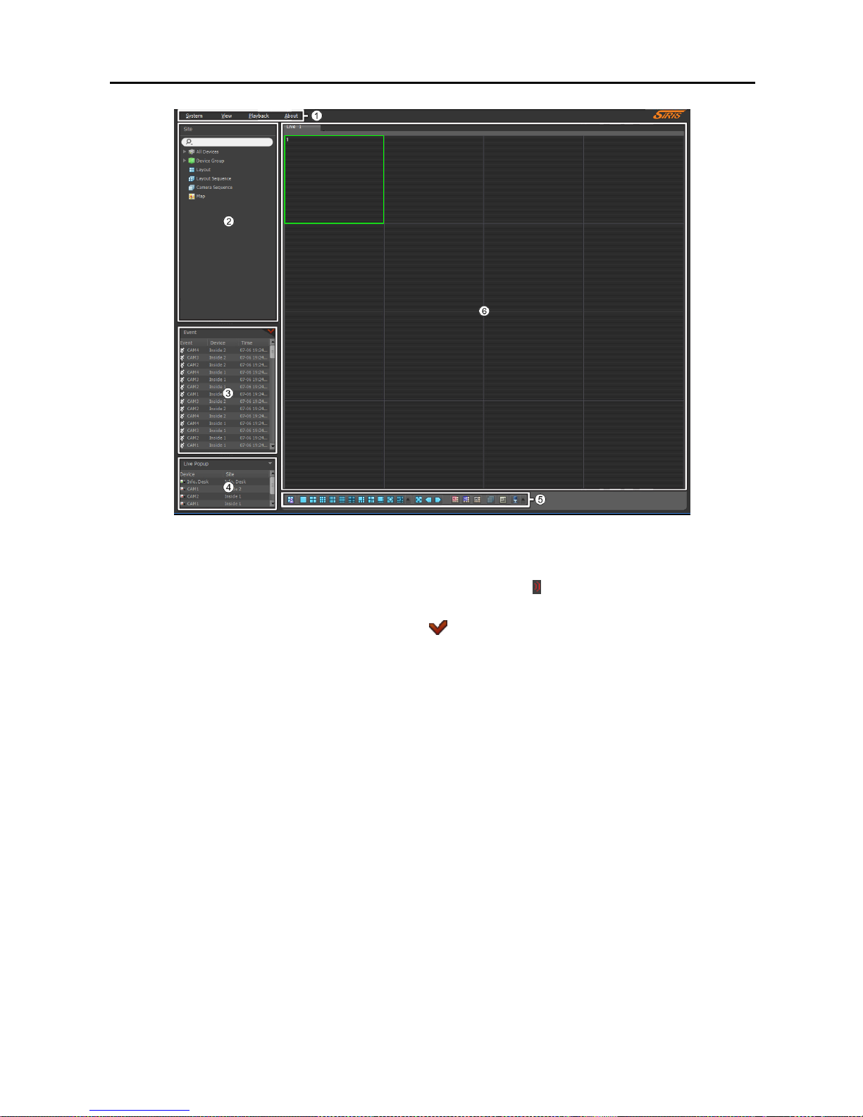
① Menu: Allows you to control the SiRiS Client program. Refer to Menu (p. 31) for details.
② Site List: Allows you to connect to the registered site by using the mouse drag and drop. Refer to Site
List (p. 32) for details. When the device uses the streaming service,
icon is displayed beside the device.
③ Instant Event List: Displays live and callback events from registered devices. Refer to Chapter 7 —
Event Handling (p. 81) for details. Clicking the
button displays the Event Manager panel. Refer
to 14.1 Setting up Event Management Schedule (p. 115) for details. Event related functions may
not be supported depending on the protocol that the device uses and device model (supported protocols:
SiRiS protocol, some versions of the Axis/Panasonic WV (DG)/ONVIF
TM
Conformance protocols). Ask
your dealer or distributor for details.
④ Live Popup List: Displays the list of live popup screens currently displayed on the monitor. Refer
to 14.2 Managing Events, Live Popup (p. 123) for details about the live popup screen.
⑤ Panel Toolbar/Timetable: Displays the toolbar or timetable depending on the panel. Refer to Chapter 4
— Live Video Monitoring (p. 41) or Chapter 6 — Recorded Video Playback & Exportation (p. 69)
for details.
⑥ Panel: Allows you to select which panel to use. Refer to Panel (p. 33) for details.
Page 39
Network Video Recorder
31
Menu
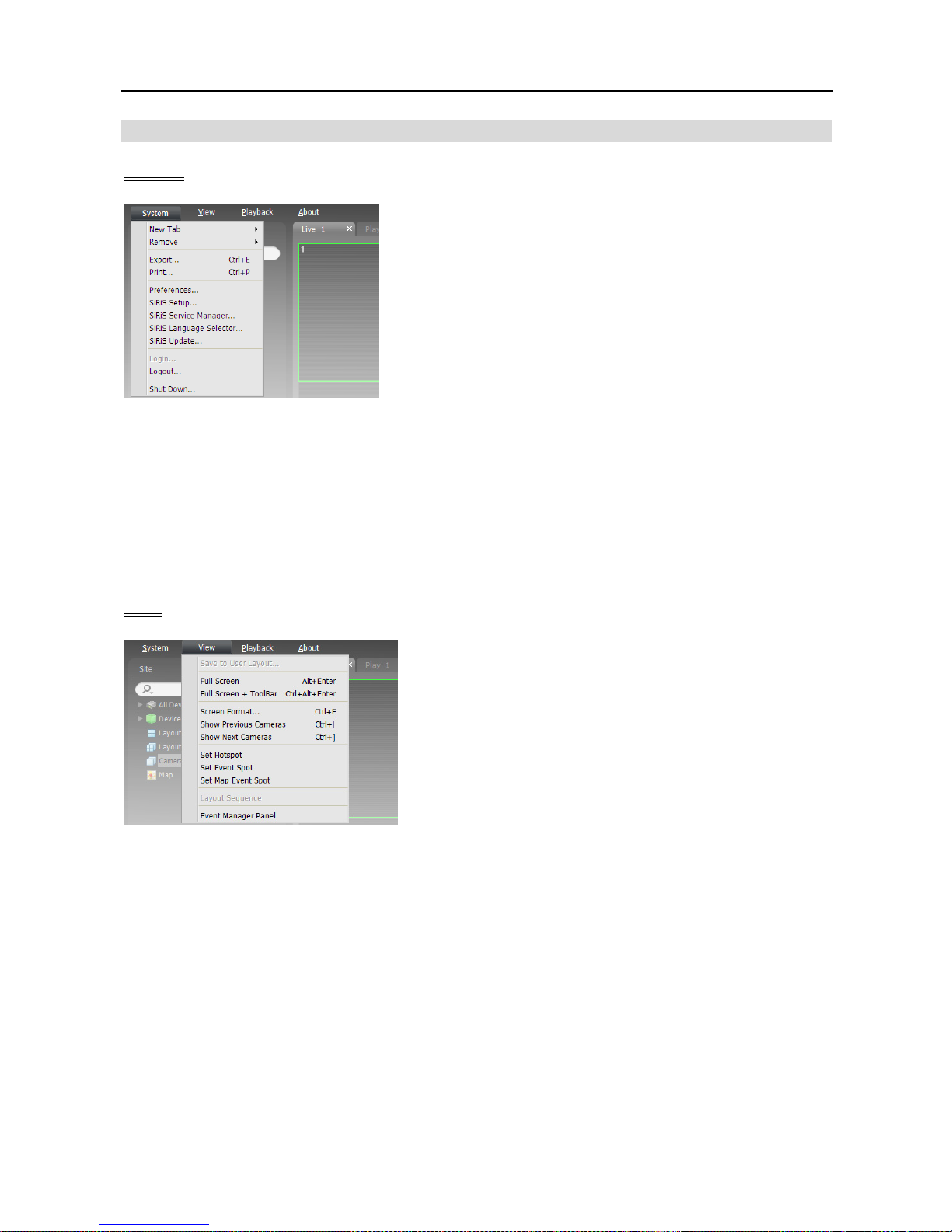
System
New Tab: Adds panels. A maximum of 12 panels are supported
for Live, Play, Backup Search, DVR Search and Map panels
altogether (no more than 2 of Map panels and no more than 4
of each for the other panels). One of each is supported for
Event, Event History, Report, Health and Status panels.
Remove: Removes selected devices or cameras or all cameras
from Live or Play screen.
Export, Print: Exports or prints images or lists displayed on
the panel on the selected tab (not supported for all panels).
Preference: Displays the Preference window allowing you to change the basic settings of the SiRiS
Client program. Refer to Menu – Preference Settings (p. 34) for details.
SiRiS Setup: Runs the SiRiS Setup program.
SiRiS Service Manager: Runs the SiRiS Service Manager program.
SiRiS Language Selector: Allows you to change the language in which to run the SiRiS program.
SiRiS Update: Allows you to upgrade the NVR system. Refer to 1.5 Upgrade (p. 3) for details.
Login, Logout, Exit: Logs in, logs out or exits the SiRiS Client program.
Shutdown: Turns off the NVR system.
View
Save to User Layout: Saves the current screen format.
Full Screen: Displays the selected Live or Play panel in
full-screen format.
Full Screen+Toolbar: Displays the selected Live or Play
panel in full-screen format with a panel toolbar.
Screen Format: Allows you to change the screen format.
Show Previous Cameras, Show Next Cameras: Moves
to the previous or next camera group.
Set Hotspot: Sets up a selected camera screen as a hotspot screen. Refer to 4.1 Monitoring Video,
Hotspot Setup (p. 42) for details.
Set Event Spot: Sets up a selected camera screen as an event spot screen. Refer to 4.1 Monitoring
Video, Event Spot Setup (p. 42) for details.
Set Map Event Spot: Sets up a selected camera screen as a map event spot screen. Refer to 4.1
Monitoring Video, Map Event Spot Setup (p. 43) for details.
Layout Sequence: Starts or stops the layout sequence. Refer to 4.1 Monitoring Video, Layout
Sequence Monitoring (p. 44) for details.
Event Manager Panel: Displays an event manager panel. Refer to Chapter 14 — Event Management
(p. 115) for details.
Page 40
User’s Manual
32
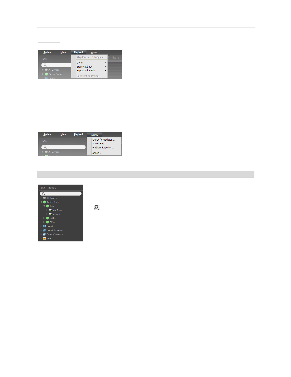
Playback
Play/Pause: Plays or pauses playback of recorded video.
Go To: Selects a specific point of video to be played. Refer
to 6.1 Playing back Recorded Video, Panel Toolbar
(p. 70) for details.
Step Playback: Moves the video forward or backward in the frame or time unit.
Export Video File: Exports recorded video as a self-player file (.exe) or an AVI file (.avi).
Snapshot on Motion: Displays snapshot of images recorded during the event-based recording (event
and pre-event) in the Play panel. Refer to 6.1 Playing back Recorded Video, Snapshot on Motion
Event (p. 73) for details.
About
Check for Updates: Displays available software upgrades.
SecretKey, ProblemReporter
: You will use them following
the directions of your dealer or distributor when your dealer
or distributor requests.
About: Displays the software version and copyright information.
Site List
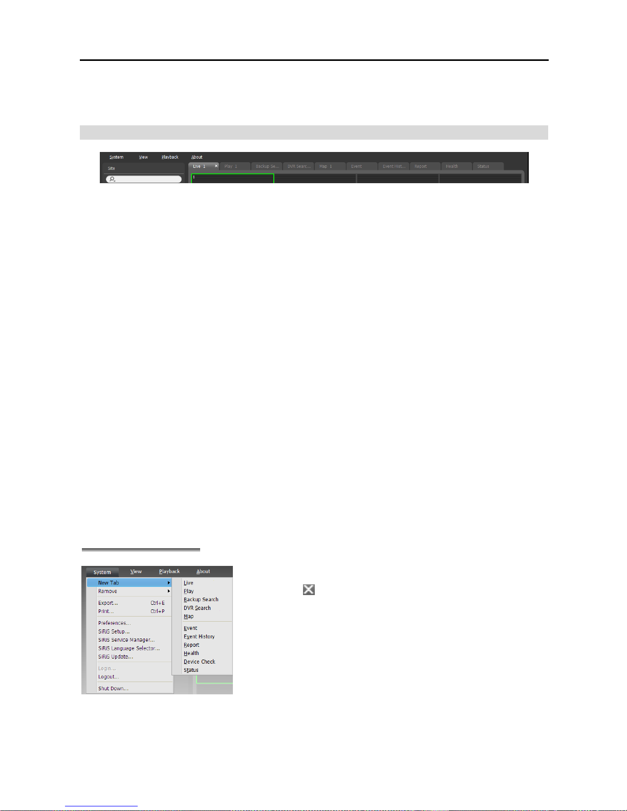
Displays the list of registered sites. The device name of the selected camera on
the screen is displayed at the top while monitoring video or playing back recorded
video.
(Incremental Search): Allows you to search for a registered device or site.
Entering text that you want to search for causes the search results to be displayed.
Search results are displayed immediately as matching text is found. As you
enter more text, the results narrow.
All Devices: Displays the list of devices registered on the NVR system. Clicking
a device in the list, and dragging and dropping it in the desired location on the
screen allows you to monitor video from the cameras connected to the device or
to play back recorded video from the cameras. This is supported only for the users
in the Administrator group.
Device Group: Displays the list of registered device groups. Clicking a device in the list, and dragging
and dropping it in the desired location on the screen allows you to monitor video from the cameras
connected to the device or to play back recorded video from the cameras. Refer to 4.1 Monitoring
Video (p. 41) or 6.1 Playing back Recorded Video (p. 69) for details.
Layout: Displays the list of registered layouts. Clicking a layout in the list, and dragging and dropping it
on the screen starts layout monitoring or playback. Refer to 4.1 Monitoring Video (p. 41) or 6.1
Playing back Recorded Video (p. 69) for details.
Layout Sequence: Displays the list of registered layout sequences. Clicking a layout sequence in the
list, and dragging and dropping it on the screen starts layout sequence monitoring. Refer to 4.1
Monitoring Video, Layout Sequence Monitoring (p. 44) for details.
Camera Sequence: Displays the list of registered camera sequences. Clicking a camera sequence in the
list, and dragging and dropping it in the desired location on the screen starts camera sequence monitoring.
Refer to 4.1 Monitoring Video, Camera Sequence Monitoring (p. 47) for details.
Page 41
Network Video Recorder
33
Map: Displays the list of registered maps. Clicking a map in the list, and dragging and dropping it in the
desired location on the screen starts map monitoring. Refer to 4.2 Map Monitoring (p. 48) for details.
Panel
Live: Displays live images. Refer to Chapter 4 — Live Video Monitoring (p. 41) for details.
Play: Allows you to play back the video recorded in the NVR system (supported only for the network
video devices). Refer to Chapter 6 — Recorded Video Playback & Exportation (p. 69) for details.
Backup Search: Allows you to play backed-up video from a backup server. (This is not supported yet.)
DVR Search: Allows you to play back video recorded in DVRs or SD (SDHC) memory cards inserted
to network cameras using the SiRiS protocol. Refer to Chapter 6 — Recorded Video Playback &
Exportation (p. 69) for details.
Map: Displays maps. Refer to 4.2 Map Monitoring (p. 48) for details.
Event: Displays the list of events recorded during Event recording. Double clicking an event in the event
list, or selecting an event in the event list and then clicking the right mouse button allows you to play back
event-recorded video and event-associated video in the play screen. Refer to Chapter 6 — Recorded
Video Playback & Exportation (p. 69) for details.
Event History: Displays log entries of events displayed on the Event Manager panel. Refer to Chapter 14
— Event Management (p. 115) for details.
Report: Displays log entries of the SiRiS program. Refer to Chapter 9 — Log Search (p. 89) for details.
Health: Displays the results of self-diagnostics for the devices. Refer to 8.1 Health Monitoring (p. 85)
for details.
Device Check: Displays the results of self-diagnostics for the devices registered on the administration
service (supported only for devices which use the SiRiS protocol). Refer to 8.2 Device Check (p. 86)
for details.
Status: Displays the status of a desired device in real-time (supported only for devices which use the
SiRiS protocol). Refer to 8.3 Status Monitoring (p. 87) for details.
NOTE: You can change the panel name by clicking the right mouse button on each panel tab.
Adding/Deleting Panel
Go to the System menu → Click New Tab → Select a panel to add.
Clicking the button beside each tab deletes the panel.
Page 42
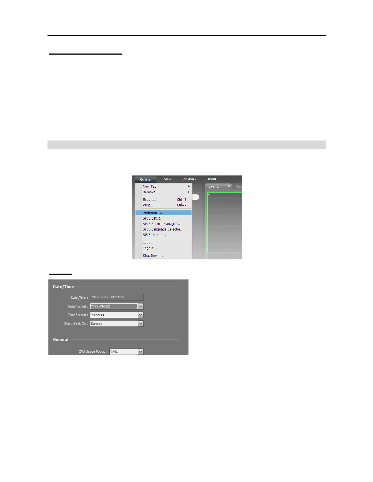
User’s Manual
34
Floating/Docking Panel
Clicking a panel tab causes it to fly out and dragging it floats the panel on the screen. Clicking the tab of
a floating panel, and dragging and dropping it to its original position docks the panel. You can change the
order of panel tabs by dragging and dropping with the mouse.
Maximizing a floating panel: Clicking the window maximize/restore button in the upper-right corner
of the floating panel maximizes or restores the window. Only one of each panel type can be maximized.
Displaying/hiding a site list in the floating panel: Clicking the right mouse button in the camera screen
of the panel and selecting the Remote Site Panel from the screen menu displays or hides a site list in
the floating panel. This is supported for not every panel.
Menu – Preference Settings
You can set the basic settings of the Client program to meet your preferences. Go to the System Menu →
Click Preference, and the Preference window appears.
System
Date/Time: Displays the current date and time.
Date Format, Time Format: Set up the system
date/time format.
Start Week On: Set up the day of the week to
start.
CPU Usage Popup: An alert message will pop
up when the CPU usage of the Client system
exceeds the assigned percentage.
Page 43
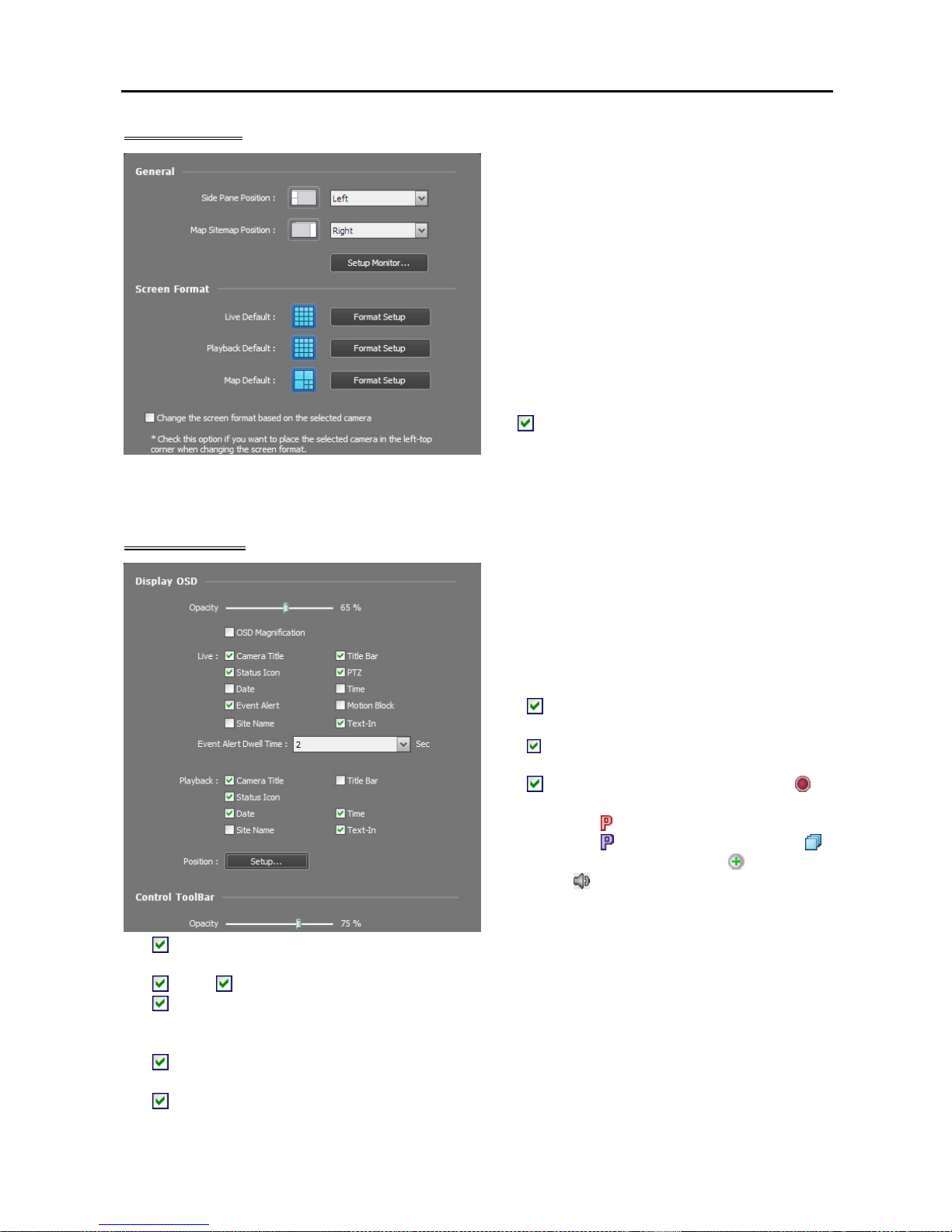
Network Video Recorder
35
Screen Format
Side Pane Position, Map Sitemap Position:
Set up the position of side panels and the position
of the root map list in the Map panel.
Monitor Setup…: Set up the monitor connected
to the NVR system. Do NOT update the device
driver of the display adaptor when setting up the
monitor. The system might not operate properly
when doing it.
Live Default, Playback Default Map Default:
The default screen formats for the Live, Play and
Map screens are displayed. Clicking the Format
Setup button allows you to change the default
screen format.
Change the screen format based on the
selected camera: Displays video from a camera
selected from the current screen format in the
first camera screen of the new screen format
when you change screen formats.
Screen Display
Display OSD: Sets up the OSD display setting
and information to be displayed on a camera
screen. The Opacity slide bar allows you to
adjust the opacity of OSD (On Screen Display),
OSD Magnification changes the OSD size
depending on the screen size. See below about
OSD information.
−
Camera Title: Displays the camera name
set in the SiRiS program.
−
Title Bar: Separates the title display area
from an image display area at the top.
−
Status Icon: Displays status OSD. (
(Red): During Time-Lapse or Event-Based
recording,
(Orange): During Instant
recording,
(Purple): In the PTZ mode,
:
In the camera sequence mode,
: In the zoom
mode,
: In the two-way audio
communication mode)
−
PTZ: Displays direction control buttons which is displayed on the camera screen when controlling
a PTZ camera.
−
Date, Time: Displays the date and time of the NVR system.
− Event Alert, Event Alert Dwell Time: Highlights the camera title bar in red when an event occurs in
the device. The alert will release after the event dwell time (sec.) from the time an event is detected or
when you select the camera screen if you set up the Event Alert Dwell Time setting to Manual Off.
−
Motion Block: Displays the area where motion is detected with red blocks when a motion detection
event occurs in the device (supported only for network video transmitters which use the SiRiS protocol).
−
Site Name: Displays the device name. This will be displayed only when the device name is different
from the camera title.
Page 44
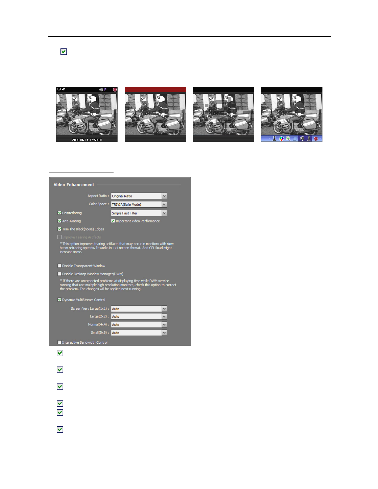
User’s Manual
36
− Text-In: Displays the text-in information on the screen when a text-in event occurs in the device
(single-screen format only). This feature is supported only for devices which use the SiRiS protocol.
Position: Allows you to change the position of the OSD.
Control Toolbar: Adjusts the opacity of the control toolbar on the camera screen.
Camera Title,
Status Icon, Date/Time
Event Alert Motion Block Control Toolbar
Video Enhancement
Aspect Ratio: Select the proper image aspect
ratio.
− Original Ratio: Fits images within the screen
size while maintaining their original ratio.
− Fit to Screen: Fits images to the screen size
regardless of the aspect ratio.
− Fit to Screen (Aspect Ratio): Fits images to
the screen size keeping the aspect ratio. This
might cause top and bottom or left and right
side of images to be cropped depending on the
screen size. This aspect ratio is not supported
and Original Ratio is applied for camera screens
that the following functions are activated: Image
Zoom, Hotspot, Event Spot, Draw Motion
Block, Draw Video Analytics.
− Actual Size (x1): Displays images in their
original size.
Color Space: Select the color space standard
to display video on the screen. The color quality
or display performance of video might be
affected depending on the color space standard
selected.
Deinterlacing: Enhances image display quality of interlaced video on the screen by eliminating
horizontal scan lines or noise in areas with motion. Select the desired deinterlace filter.
Anti-Aliasing: Enhances image display quality of video on the screen by eliminating stair-stepping
(aliasing) effects in the enlarged image.
Important Video Performance: Gives priority to display speed over the display quality on the screen
when displaying video.
Trim The Black (noise) Edges: Trims the black line (noise) displayed at the edge of the image.
Improve Tearing Artifact: Improves tearing artifact caused when the monitor’s scanning line retracing
speed is slow (1x1 screen format only). This might increase the CPU load.
Disable Transparent Window: Disables using a transparent window style and opacifies windows
including the control toolbar to correct the problem of transparent areas of the window flickering. The
change will be applied the next time the program is run.
Page 45
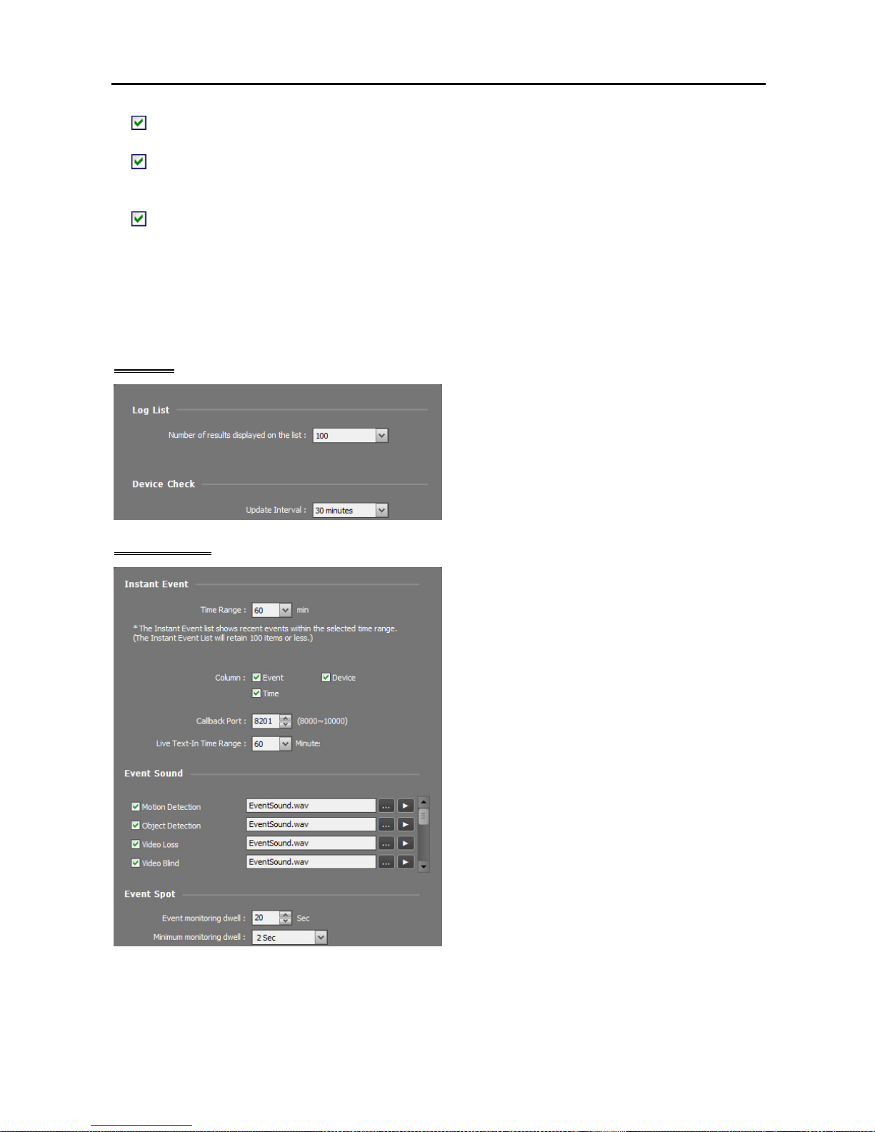
Network Video Recorder
37
Disable Desktop Window Manager (DWM): Disables Desktop Window Manager (DWM) that runs
Windows Aero. Disabling DWM is recommended if video often freezes when multiple monitors are used.
Dynamic Multistream Control: Allows you to use a different stream depending on the screen format
(supported only for devices in which more than one stream is used). Selecting Auto allows the SiRiS
program automatically to choose the proper stream based on the screen format.
Interactive Bandwidth Control: Controls the network bandwidth by automatically adjusting the
resolution and the frame rate of the device depending on a screen format (1x1 screen format: the maximum
resolution and frame rate supported by the device, Multi-screen format: the resolution and frame rate
decreased to an appropriate level for each screen format). This function enhances the network bandwidth
efficiency and decreases a drop in performance of the Client system which might be caused by the network
congestion. For this function to work, the device must be also set up to use the function. This function
works only for monitoring video.
Log List
Number of results displayed on the list: Set
up the number of log entries to be displayed at
once (in the case of Device Log, maximum
100 logs at once regardless of the setting).
Update Interval: Set up the status update
interval in the Device Check panel.
Instant Event
Time Range: Set up the length of time for an
event notification to be displayed in the Instant
Event List after notification of the event detection
(If the event list has 100 or fewer items, the event
list will remain on the Instant Event List even
if the length of time has expired).
Column: Select the information to be displayed
in Instant Event List.
Callback Port: Set up the port number to receive
a callback message from the device. This setting
will be used only when the monitoring service
does not run. The NVR system uses the callback
port of the monitoring service, which is set in the
Service Manager program when the monitoring
service runs. The port number you enter should
match the port number set on the device for
remote callback.
Live Text-In Time Range: Set up the length of time for a text-in data to be displayed when a text-in
event occurs. You can check the text-in data in the text-in viewer window within the time range since
the text-in event occurred. Refer to 4.3 Controlling Cameras, Text-In Viewer (p. 53) for details about
the text-in viewer window.
Page 46
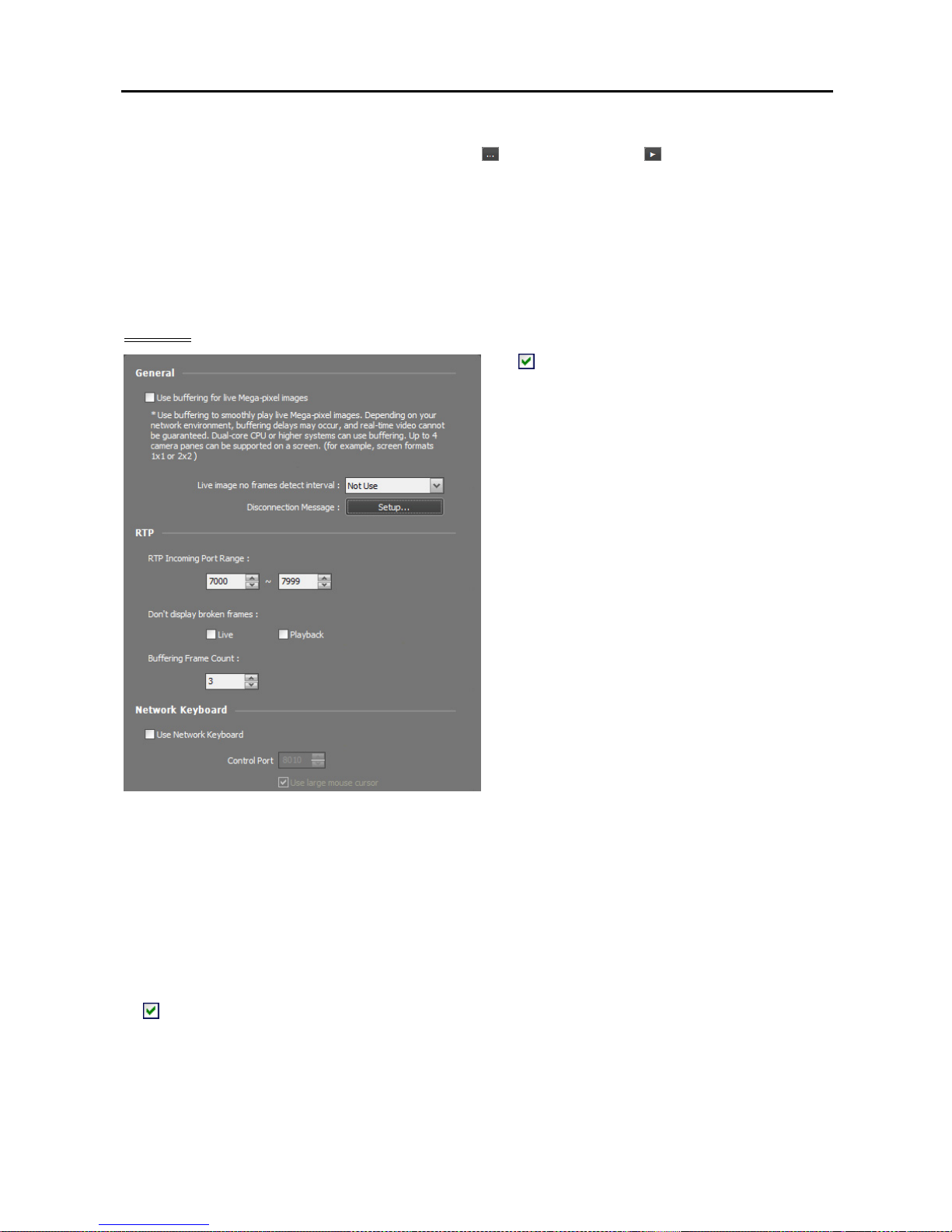
User’s Manual
38
Event Sound: Set up to sound by playing back an audio file when an event is detected. Select a desired
event and set up an audio file (.wav) by clicking the
button. Clicking the button allows you to test
the sound by playing back the selected audio file.
Event Spot: Video from the event-detected camera is displayed on the event spot screen when an event
is detected.
− Event monitoring dwell: Set up the duration for video to be displayed on the event spot screen.
− Minimum monitoring dwell: Set up the event monitoring dwell time for the current event when other
events are detected while event-detected video is displayed. Video from other events is displayed after
the preset time expires.
Network
Use buffering for live Mega-pixel images:
Displays images on the screen more smoothly
by using buffering when monitoring mega-pixel
video images (supported only for devices which
use the SiRiS protocol). Buffering may be
delayed or real-time monitoring may decrease
depending on the network environment. This
function is supported only in a dual-core CPU
or higher systems for up to four cameras in each
Live panel.
Live image no frames detect interval: Set
up the interval to check video frame transfer
from a device to the NVR system. A message
will be displayed on the camera screen when
no video frame is transferred during the period.
Disconnection Message: Allows you to
change the text of the screen message which is
displayed when a device is disconnected. Click
the Setup button, check the box beside each
message and change the text.
RTP Incoming Port Range: Set up the port range if a device which transmits images using the RTP
protocol is registered. Port range settings must be changed if the network firewall or local network allows
only specific UDP/RTP port numbers. The port numbers should not conflict with the RTP port number
of the NVR system or port numbers of other streaming programs. If an RTP port number conflicts with
others, monitoring may not be available.
Don’t display broken frames: It is possible that frames will be broken or lost when using the RTP protocol
depending on the network environment. Select whether or not to display the broken frames in Live or
Play panels.
Buffering Frame Count: Set up the number of buffering frames to use for the RTP protocol. The higher
the number is, the less the video stutter. The lower the number is, the higher the real-time monitoring.
Use Network Keyboard: Allows you to control the Client program by using a network keyboard.
Set up the port number that the Client program will use when it is controlled by a network keyboard.
Selecting Use large mouse cursor enlarges the mouse cursor size.
Page 47
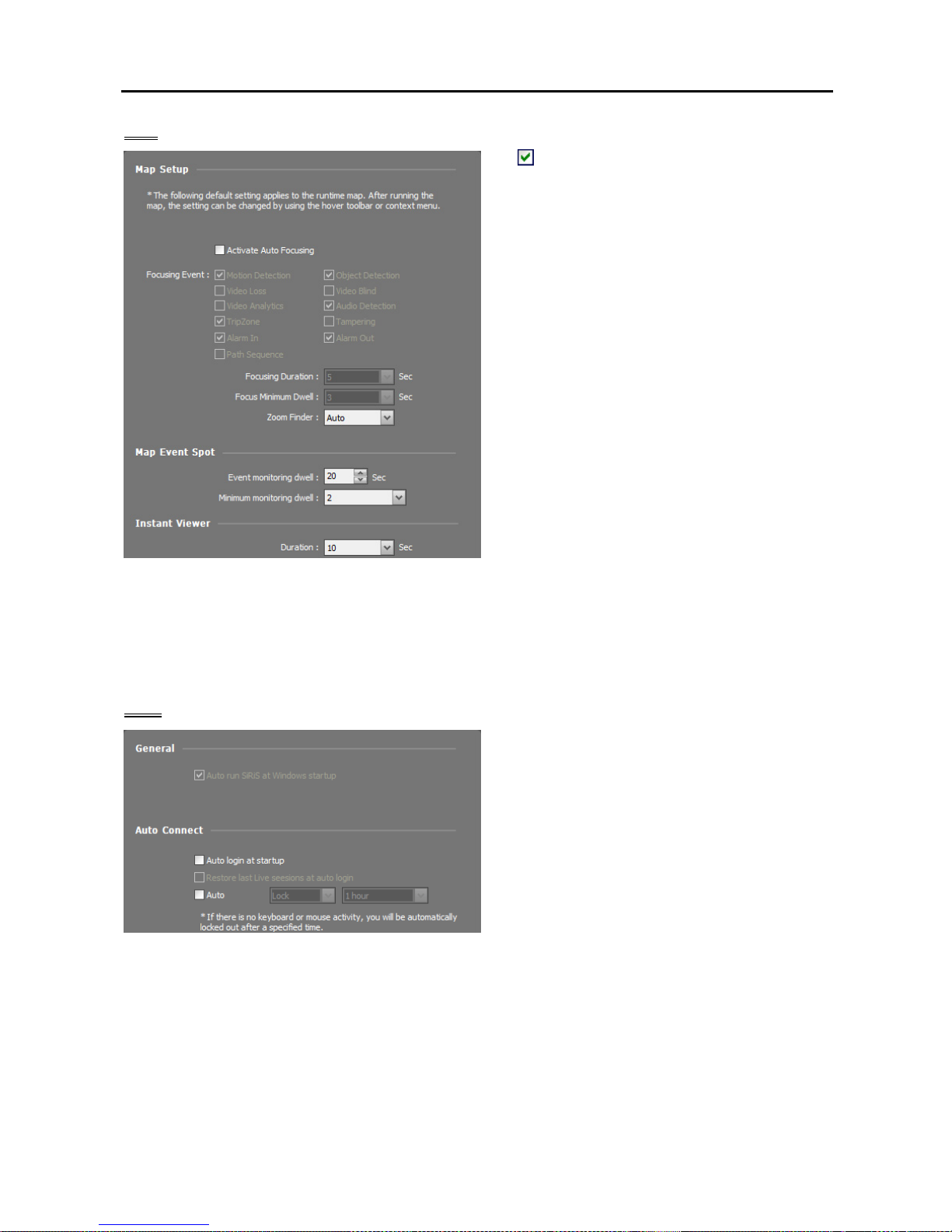
Network Video Recorder
39
Map
Activate Auto Focusing: Enlarges the area
where the event-detected device is placed when
an event is detected.
− Focusing Event: Select a desired event for
auto focusing.
− Focusing Duration: Set up the duration for
auto focusing to last.
− Focusing Minimum Dwell: Set up the duration
for auto focus to last for the first detected event
when events are detected in more than one
device consecutively. Auto focusing moves
to the later detected event after the preset time
expires.
Zoom Finder: Displays or hides the PIP screen.
The rectangle in the PIP screen indicates the
enlarged area. When set to Auto, the PIP screen
is displayed only while a canvas is enlarged.
Map Event Spot: Video from the event-detected
camera is displayed on the map event spot screen
when an event is detected.
− Event monitoring dwell: Set up the duration for video to be displayed on the map event spot screen.
− Minimum monitoring dwell: Set up the event monitoring dwell time for the current event when other
events are detected while event-detected video is displayed. Video from other events is displayed after
the preset time expires.
Instant Viewer: Set up the duration for the instant view to be displayed. Instant Viewer is displayed
when clicking a camera on a map.
User
Auto run SiRiS Client at Windows startup:
The Client program automatically runs when
logging onto Windows. This is supported in the
Client system.
Auto login at startup: The Client program
automatically logs in with the login information
from the previous connection when it starts.
Checking the Restore last Live sessions at
auto login box restores the previous live
monitoring sessions in the current Live panels.
Auto: The Client program automatically logs
out or the Client system is locked out depending
on the setting when there are no mouse or
keyboard inputs for the specified time.
Page 48

User’s Manual
40
Page 49
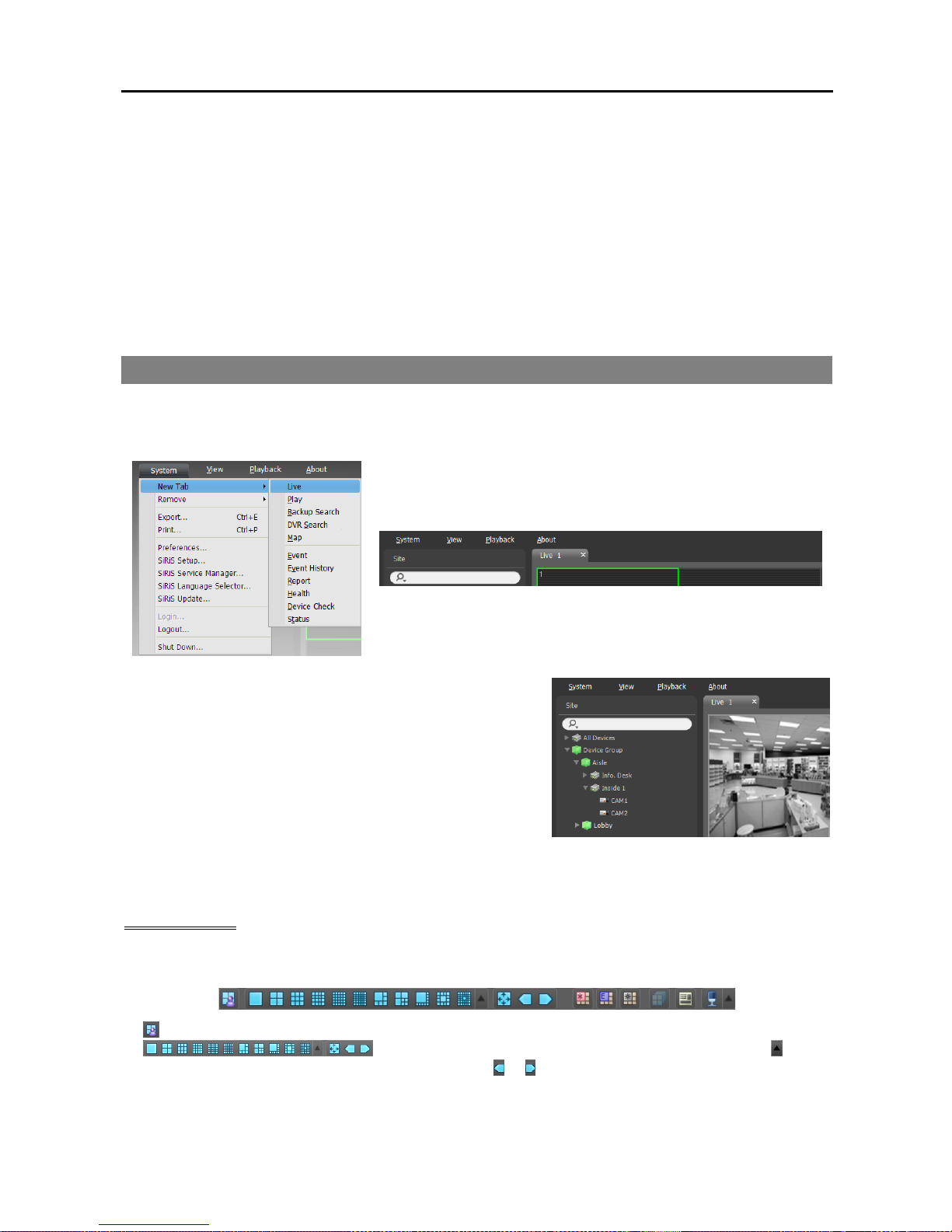
Network Video Recorder
41
Chapter 4 — Live Video Monitoring
You can monitor live video of each group. The Client system displays video from devices based on the
settings in the device on the Live screen.
First, check the following.
Devices should be added to a device group. Refer to Chapter 11 — Device Management (p. 93) for
details.
4.1 Monitoring Video
Live video monitoring is supported in the Live panel (maximum 4). If the Live tab is not on the tab panel,
go to the System menu, click New Tab, and then Live.
Click the Live tab on the tab panel → Select a camera, device
or device group from the Site list, and drag and drop it on the
Live screen. Live video from each camera is displayed on the
screen. You can move a camera screen to the desired location
on the Live screen without disconnecting the current connection
while monitoring video. Select a camera screen and drag and
drop it on the desired location.
NOTE: The system performance might seriously deteriorate when simultaneously monitoring or playing back
video with 1280x720 or higher resolution on more than one camera screen.
Panel Toolbar
The panel toolbar at the bottom allows you to control the Live panel.
(Save to User Layout): Saves the current screen format.
(Screen Format): Changes the screen format. Clicking the button
displays more available screen formats. Clicking the
or button moves to the previous or next camera
groups.
Page 50
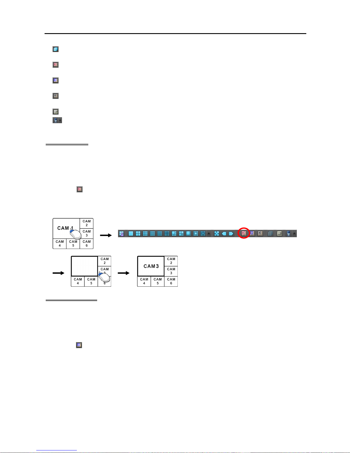
User’s Manual
42
(Layout Sequence): Starts or stops layout sequence. Refer to 4.1 Monitoring Video, Layout
Sequence Monitoring (p. 44) for details.
(Hotspot): Sets up a selected camera screen as a hotspot screen. Refer to Hotspot Setup (p. 42) for
details.
(Event Spot): Sets up a selected camera screen as an event spot screen. Refer to Event Spot Setup
(p. 42) for details.
(Map Event Spot): Sets up a selected camera screen as a map event spot screen. Refer to Map Event
Spot Setup (p. 43) for details.
(Export/Print Image): Allows you to export or print the images currently displayed on the screen.
(Audio Broadcast): Broadcasts audio to all devices in the current Live tab. Clicking an arrow button
allows you adjust the audio volume of the NVR system.
Hotspot Setup
NOTE: The “hotspot” in the SiRiS program is a predefined camera screen in which video from any camera
among those currently displayed can be monitored with emphasis. The hotspot screen is surrounded by a
red outline.
1. Select a camera screen to set up as a hotspot screen on the current monitoring screen.
2. Click the
(Hotspot) button on the toolbar at the bottom of the Live panel, and the current connection
in the selected camera screen is released. The hotspot screen is surrounded by a red outline.
3. Select any camera on the screen. Video from the selected camera is displayed on the hotspot screen, and
you can control the camera.
Event Spot Setup
NOTE: The “event spot” in the SiRiS program is a predefined camera screen in which video from a camera
which an event is detected among cameras currently displayed can be monitored with emphasis. The event
spot screen is surrounded by a blue outline.
1. Select a camera screen to set up as an event spot screen on the current monitoring screen.
2. Click the
(Event Spot) button on the toolbar at the bottom of the Live panel, and the current connection
in the selected camera screen is released. The event spot screen is surrounded by a blue outline.
3. When an event is detected, video from the event-detected is displayed on the event spot screen.
Page 51
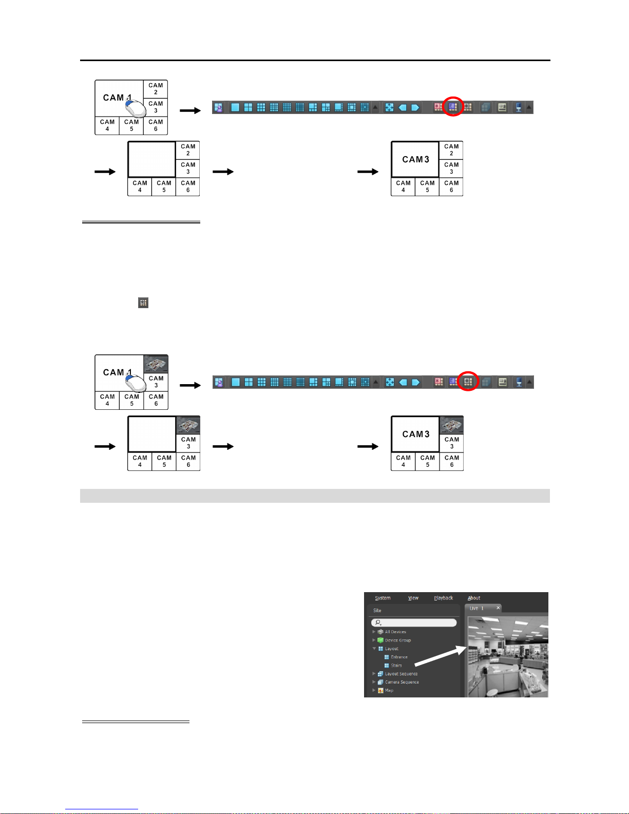
Network Video Recorder
43
CAM3:
An event is detected.
Map Event Spot Setup
NOTE: The “map event spot” in the SiRiS program is a predefined camera screen in which video from a camera
which an event is detected among cameras on a map can be monitored with emphasis. The map event spot
screen is surrounded by a gray outline.
1. Select a camera screen to set up as a map event spot screen on the current monitoring screen.
2. Click the
(Map Event Spot) button on the toolbar at the bottom of the Live panel, and the current
connection in the selected camera screen is released. The map event spot screen is surrounded by a gray
outline.
3. When an event is detected, video from the event-detected is displayed on the map event spot screen.
[Map] CAM3:
An event is detected.
Layout Monitoring
You can monitor video from multiple cameras in a predefined layout. A layout should be registered on the
NVR system for layout monitoring. Refer to the following explanation for details about layout registration.
NOTE: A “layout” in this document refers to a screen organization created by arranging specific cameras
in a specific screen format.
Select a desired layout from the Layout list, and drag and drop
it on the Live screen. Video from cameras added to the Layout
is displayed in the predefined screen format on the screen.
Registering Layouts
1. Go to the System menu, and click SiRiS Setup, and select the Device menu.
Page 52
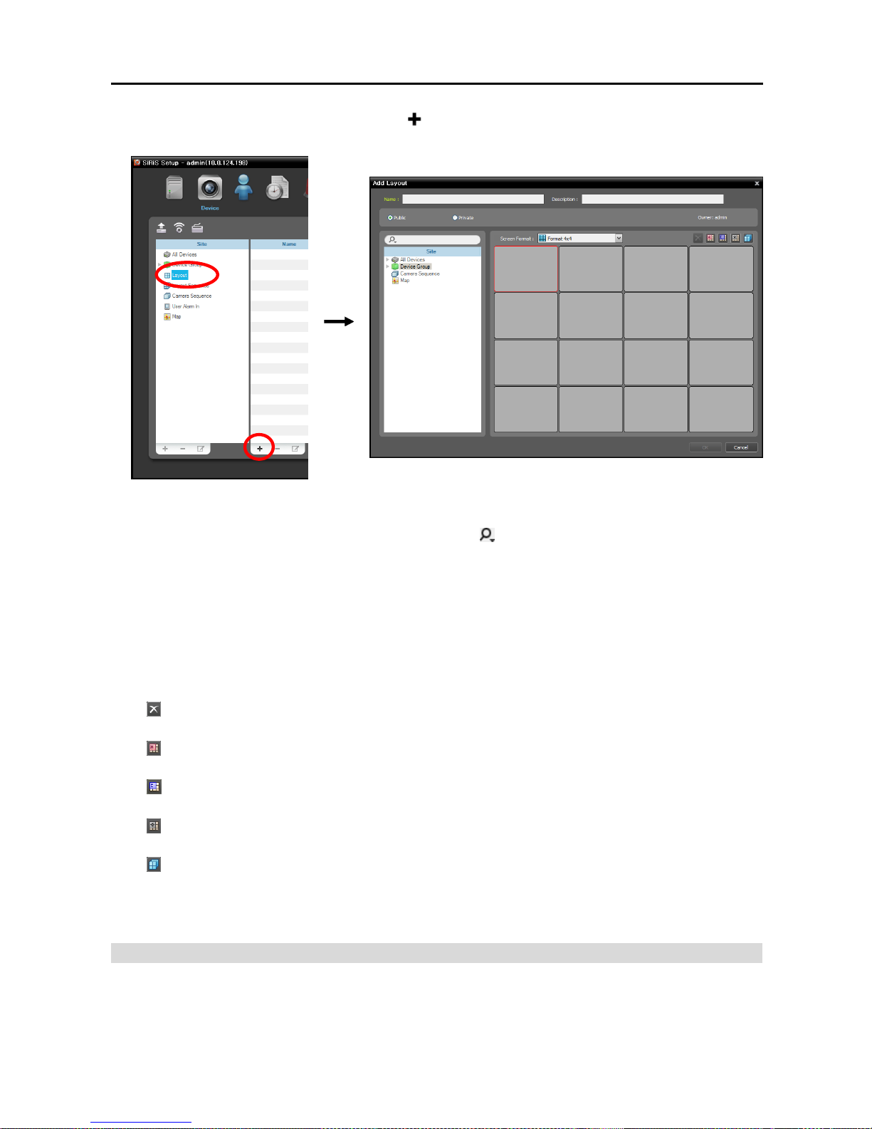
User’s Manual
44
2. Click Layout in the Site panel, and then the button at the bottom of the Site List panel on the right.
The Add Layout window appears.
Name: Enter the layout name.
Site: Displays a list of registered devices, cameras or camera sequences. You can search for a registered
device or camera sequence by entering text beside the icon. Entering text that you want to search
for causes the search results to be displayed. Search results are displayed immediately as matching
text is found. As you enter more text, the results narrow.
Public/Private: Displays the layout to all users (Public) or to a current user only (Private). The admin
user can see all layouts.
Owner: Displays the user ID of the person who created the layout.
Screen Format: Select a screen format for the layout to be registered. Select a device, a camera or
camera sequence to assign to the layout in the Site panel, and drag and drop it in the desired camera
screen of the layout screen.
(Remove): Selecting a camera screen in the layout screen and clicking this button deletes the camera
assigned to the camera screen from the layout screen.
(Hotspot): Selecting a camera screen in the layout screen and clicking this button sets up the camera
screen as a hotspot screen.
(Event Spot): Selecting a camera screen in the layout screen and clicking the button sets up the camera
screen as an event spot screen.
(Map Event Spot): Selecting a camera screen in the layout screen and clicking the button sets up
the camera screen as a map event spot screen.
(Camera Sequence): Selecting a camera screen in the layout screen and clicking this button allows
you to create a camera sequence and assigns the created camera sequence to the camera screen.
Clicking the OK button completes registration of the layout.
Layout Sequence Monitoring
You can monitor video from multiple cameras sequentially in more than one predefined layout. A layout
sequence should be registered on the NVR system for layout sequence monitoring. Refer to the following
for details about layout sequence registration.
Page 53
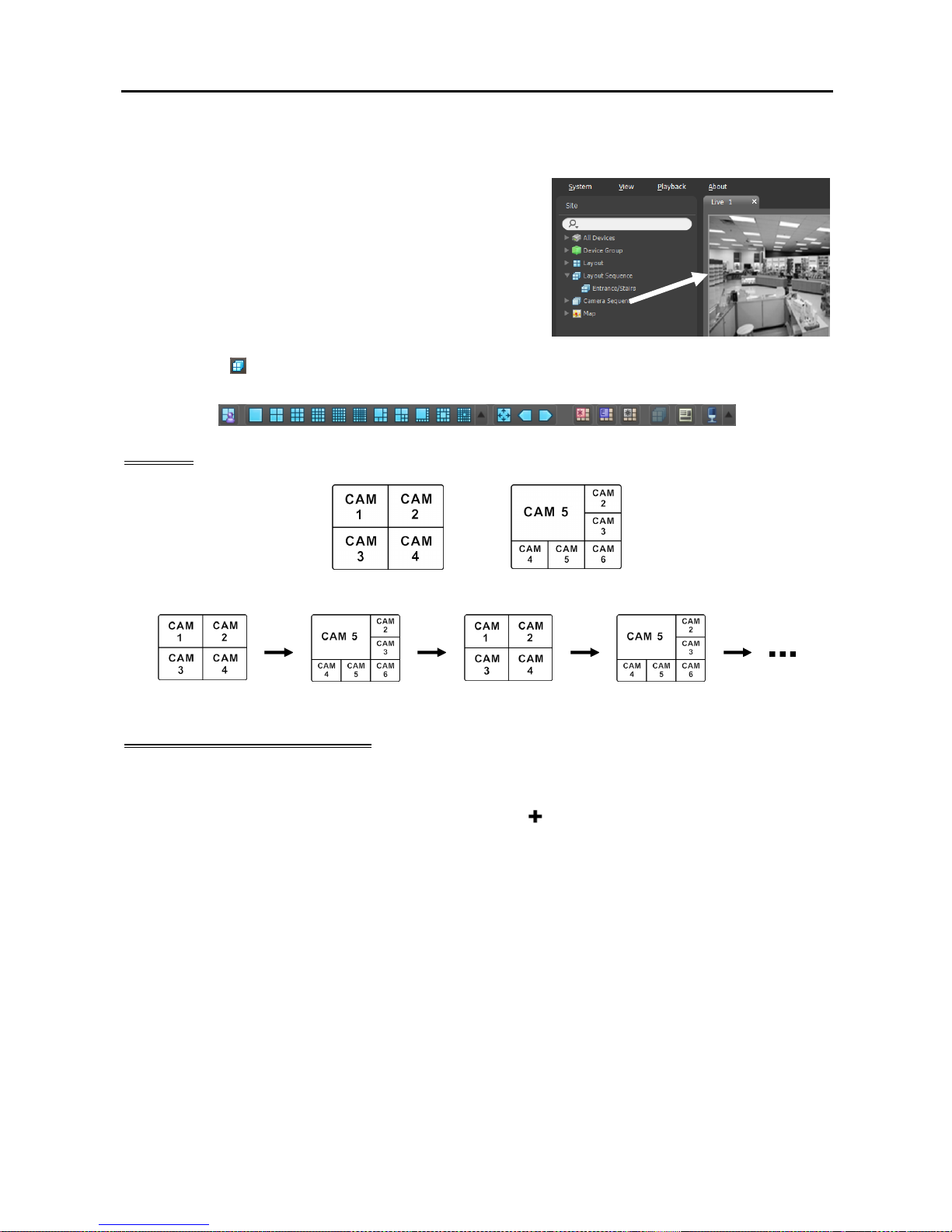
Network Video Recorder
45
NOTE: A “layout” in this document refers to a screen organization created by arranging specific cameras
in a specific screen format.
1. Select a desired layout sequence from the Layout Sequence
list, and drag and drop it on the Live screen. Video from
cameras added to the layout sequence is displayed in the
screen format for each layout sequentially.
2. Clicking the
(Layout Sequence) button of the toolbar at the bottom of the panel stops or starts the
layout sequence.
Example
Layout 1 Layout 2
Layout Sequence
Registering Layout Sequences
1. Go to the System menu, and click SiRiS Setup, and select the Device menu.
2. Click Layout Sequence in the Site panel, and then the
button at the bottom of the Site List panel
on the right. The Add Layout Sequence window appears.
3. If no layout to be sequenced is registered, click the Add Layout button. The Add Layout window appears.
Register layouts to sequence referring to Layout Monitoring (p. 43). At least two layouts must be
registered for sequencing.
Page 54
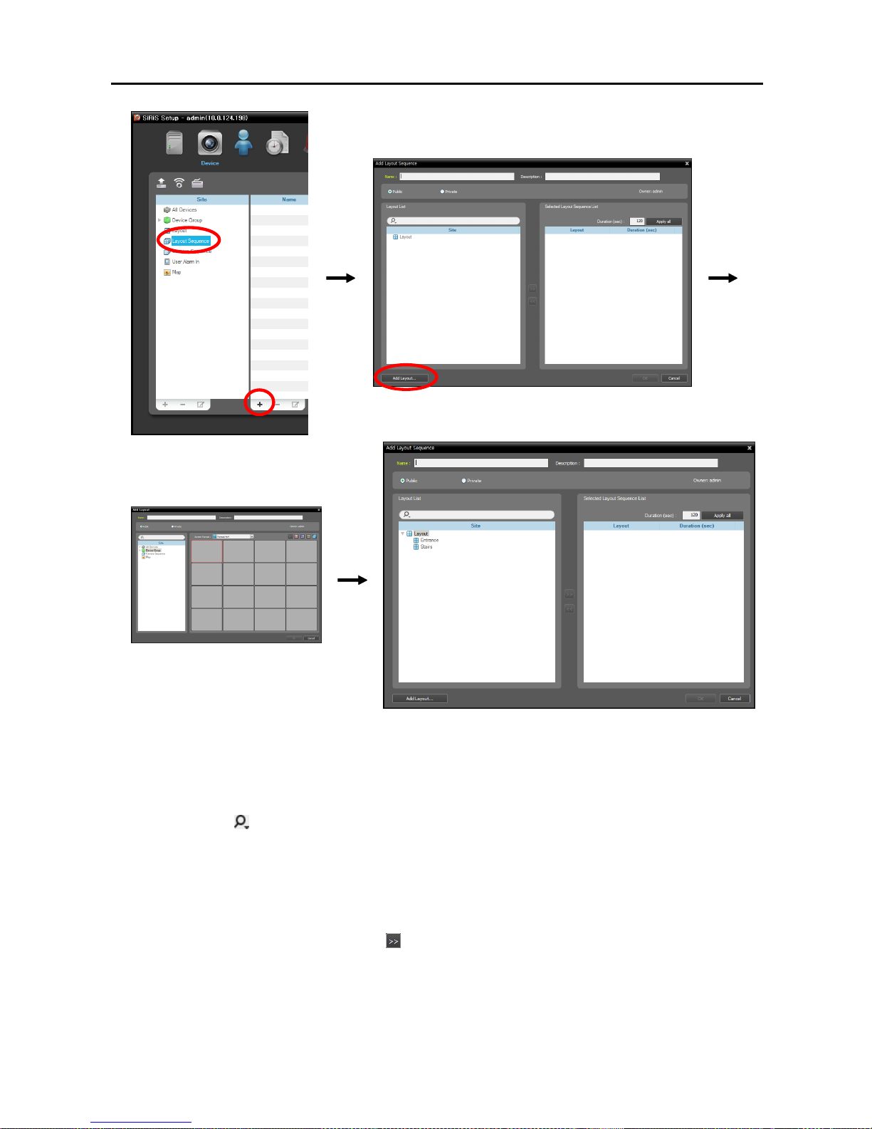
User’s Manual
46
Name: Enter the layout sequence name.
Public/Private: Displays the layout sequence to all users (Public) or to a current user only (Private).
The admin user can see all layout sequences.
Owner: Displays the user ID of the person who created the layout sequence.
Layout List: Displays a list of registered layouts. You can search for a registered layout by entering
text beside the icon. Entering text that you want to search for causes the search results to be displayed.
Search results are displayed immediately as matching text is found. As you enter more text, the results
narrow.
Selected Layout Sequence List: Displays the list of layouts registered for the layout sequence.
Duration (sec) displays the duration for each layout to be displayed on the screen. Clicking the Apply
all button applies the duration setting to all layouts in the list.
Select a layout from Layout List, click the button, and the selected layout is added to Selected Layout
Sequence List. Clicking the OK button completes registration of the layout sequence.
Page 55
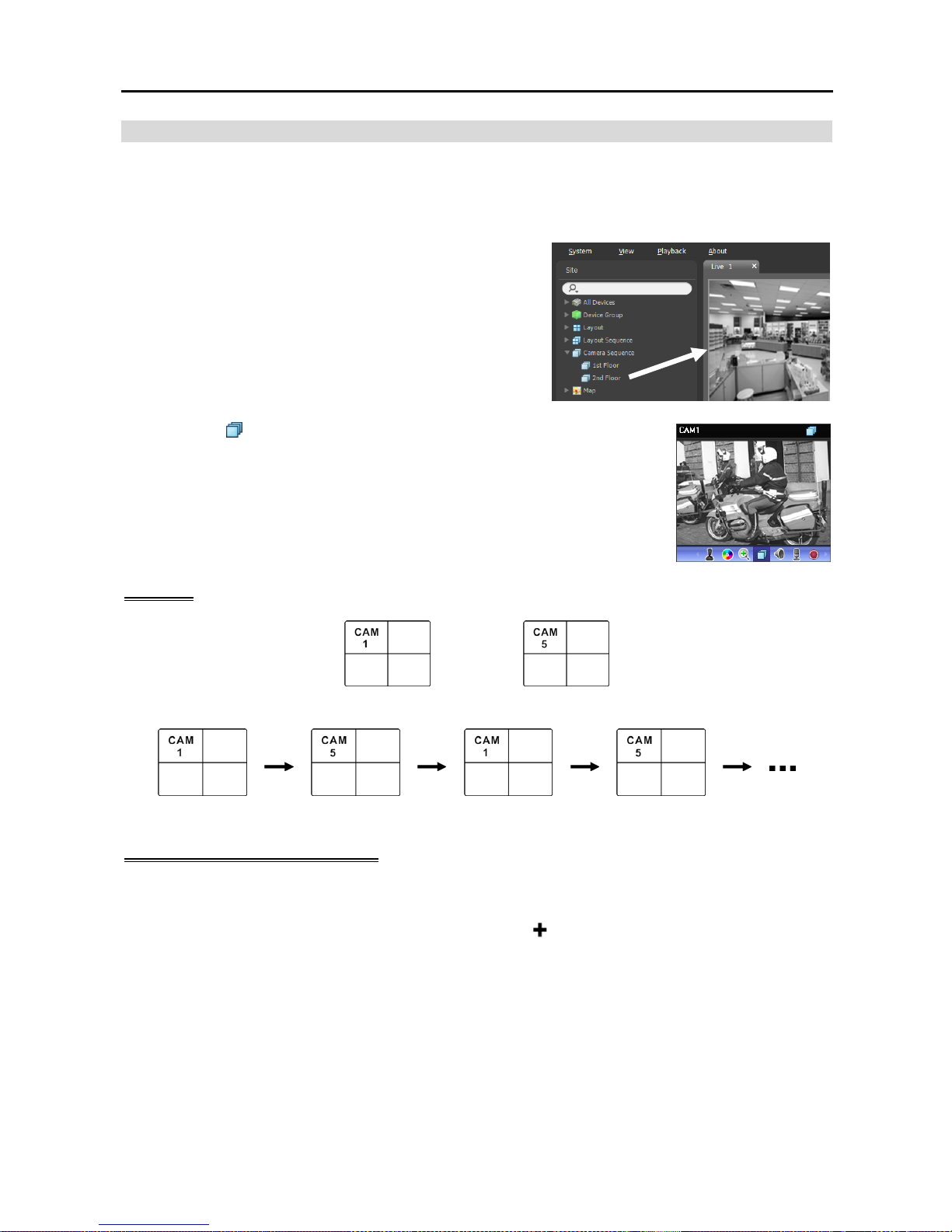
Network Video Recorder
47
Camera Sequence Monitoring
You can monitor video from multiple cameras in the same camera screen sequentially. A camera sequence
should be registered on the NVR system for camera sequence monitoring. Refer to the following for details
about camera sequence registration.
1. Select a desired camera sequence from the Camera
Sequence list, and drag and drop it on the Live screen.
Video from cameras added to the camera sequence is
displayed on the screen sequentially.
2. Clicking the
(Camera Sequence) button on the camera screen control toolbar
stops or starts the camera sequence.
Example
Camera 1 Camera 2
Camera Sequence
Registering Camera Sequences
1. Go to the System menu, and click SiRiS Setup, and select the Device menu.
2. Click Camera Sequence in the Site panel, and then the
button at the bottom of the Site List panel
on the right. The Add Camera Sequence window appears.
Page 56
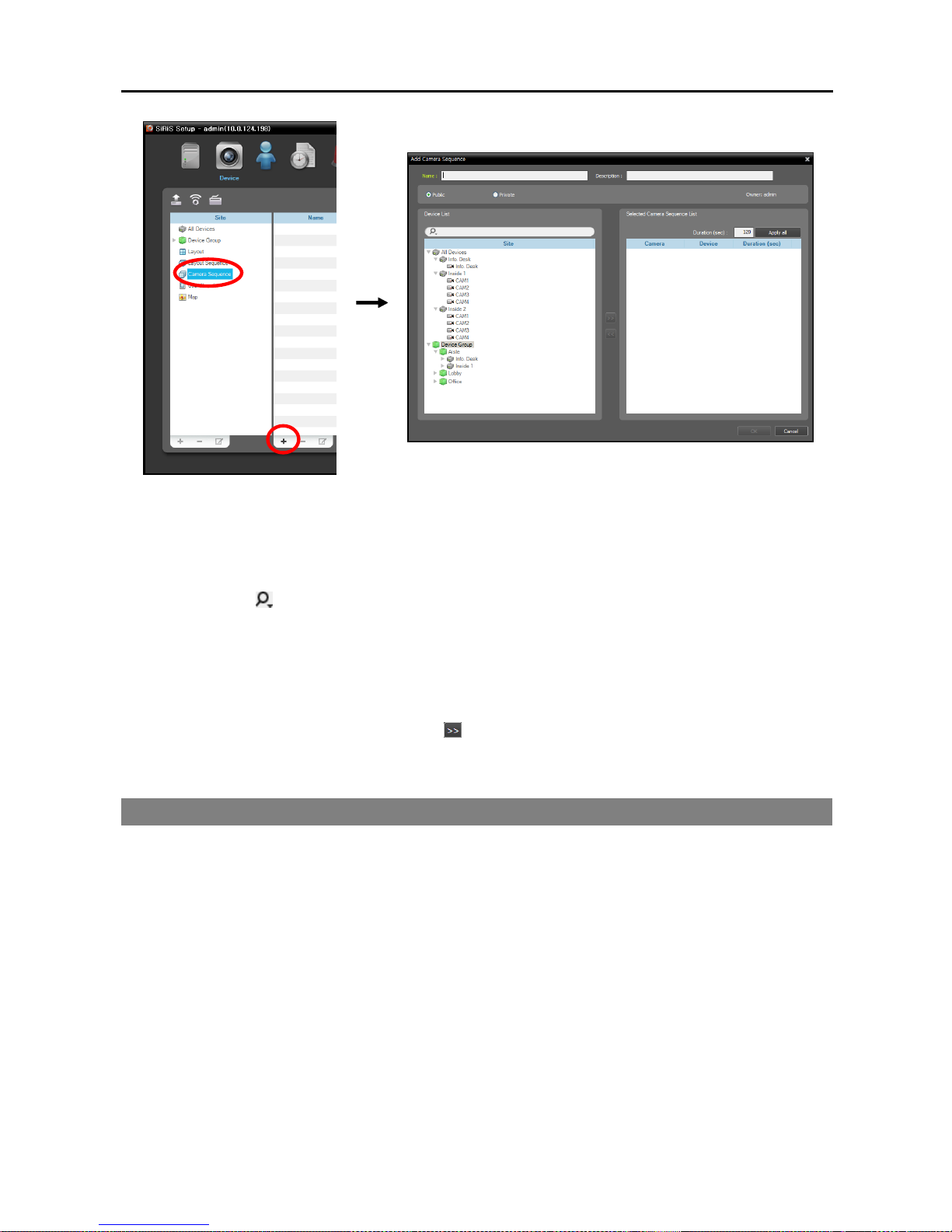
User’s Manual
48
Name: Enter the camera sequence name.
Public/Private: Displays the camera sequence to all users (Public) or to a current user only (Private).
The admin user can see all camera sequences.
Owner: Displays the user ID of the person who created the camera sequence.
Device List: Displays a list of registered devices. You can search for a registered device by entering
text beside the icon. Entering text that you want to search for causes the search results to be displayed.
Search results are displayed immediately as matching text is found. As you enter more text, the results
narrow.
Selected Camera Sequence List: Displays the list of cameras registered for the camera sequence.
Duration (sec) displays the duration for video from each camera to be displayed on the screen. Clicking
the Apply all button applies the duration setting to all cameras in the list.
Select a camera from Device List, click the button, and the selected camera is added to Selected
Camera Sequence List. Clicking the OK button completes registration of the camera sequence.
4.2 Map Monitoring
You can monitor video from cameras, event detection and input/output device status on a map for devices
registered on the NVR system. A map should be registered on the administration service for map monitoring.
Refer to Chapter 15 — Map Editor (p. 127) for details about map registration.
Map monitoring is supported in the Live panel (maximum 4) and Map panel. If the Live or Map tab is not
on the tab panel, go to the System menu, click New Tab, and then Live or Map.
Page 57
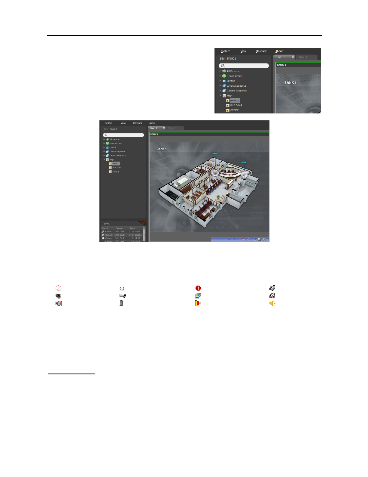
Network Video Recorder
49
Select a desired map from the Map list, and drag and drop it on
the Live screen. The selected map is displayed on the screen.
You can move a map to the desired location on the Live screen
without disconnecting the current connection while monitoring
video. Selecting an input/output device on the map, and dragging
and dropping it on the Live screen, Play panel or Device Status
panel allows you to monitor or play back video or to monitor
device status.
Hovering the mouse cursor over the input/output device on the map displays the event detection and status
of the input/output device. When the input/output device detects any event or is not working properly, the
following icons appear sequentially to the maximum of 4 at a time (some event icons may not be supported,
depending on the specifications and version of the device):
Unplugged Event-Off Irregular
Motion
Video Blind Video Loss Object Detection
Trip-Zone
Tampering Audio Detection Alarm-In
Alarm-Out
Event detection is displayed according to the event detection settings, and Irregular is based on the system
check settings on the device that the input/output device is connected.
Event detection and status are displayed in unique colors if you have set up status color during the map setup.
When more than one event or status is detected at the same time, the color reflecting each event detection
or status is displayed sequentially.
Path Sequence
You can monitor video from multiple cameras sequentially on a map in the same camera screen during map
monitoring. A path sequence should be set up for path sequence monitoring. Refer to 15.2 Setting up
Map, Path Sequence (p. 130) for details about the path sequence setup.
Page 58
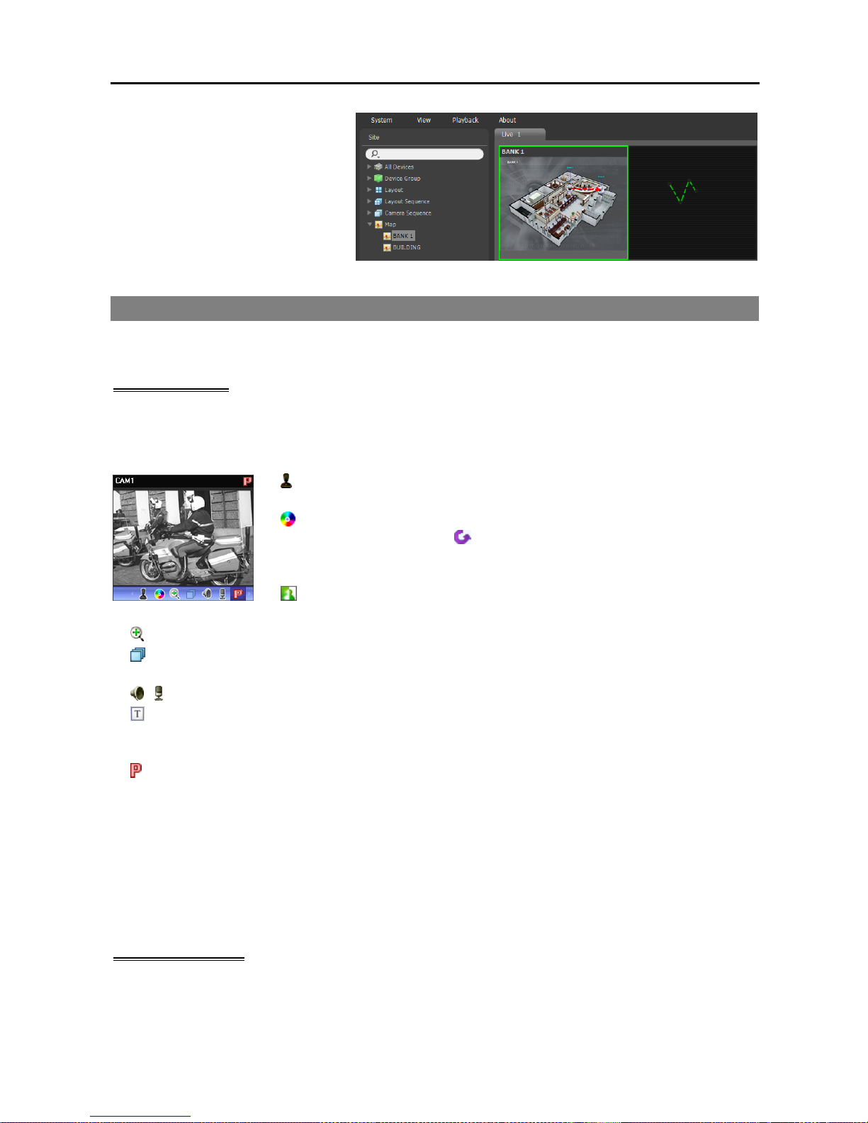
User’s Manual
50
Select a desired path of the path
sequence from the map, and drag and
drop it on the Live screen. Video from
the cameras associated to the path
sequence is displayed sequentially
during the preset duration period.
4.3 Controlling Cameras
A control toolbar and a screen menu are provided for controlling camera.
Control Toolbar
When selecting a camera screen and hovering the mouse cursor over the camera screen, the control toolbar
is displayed over that camera screen. The control toolbar allows you to control the selected camera. Hovering
the mouse cursor over a button displays a tooltip for the button.
(PTZ Control): Allows you to control PTZ for a camera that supports PTZ
control. Refer to PTZ Control (p. 51) for details.
(Color Control): Adjusts the brightness, contrast, saturation and hue of the
current video. Clicking the button cancels the adjustment and reloads the
original image. This change will be applied to both the video of the SiRiS
program and the device.
(Image Effect): Adjusts the image effect. Refer to Image Effect (p. 53)
for details.
(Image Zoom): Zooms in on the image. Refer to PTZ Control (p. 51) for details.
(Camera Sequence): Starts or stops camera sequence. Refer to 4.1 Monitoring Video, Camera
Sequence Monitoring (p. 47) for details.
/ (Listen/Talk): Receives audio from the device or sends audio to the device.
(Text-In Viewer): Pops up the text-in viewer window (supported only when a text-in event is detected).
The camera title bar is highlighted in blue when a text-in event is detected. Refer to Text-In Viewer (p. 53)
for details.
(Instant Recording): Starts or stops the Instant recording (supported only for devices registered on one
of recording services). During Instant recording, the Instant Recording OSD is displayed in the upperright corner of the camera screen and Time-Lapse recording or Event-Based recording stops. Recording
might be delayed depending on system congestion, and the recording OSD might be displayed later or
for longer than the scheduled time. Refer to 5.1 Setting up Recording Schedule, Setting up Instant
Recording (p. 66) for details.
NOTE: The instant recording is a function that allows you to manually record video which is currently being
monitored. You can record desired video with higher performance if the codec, resolution, frame rate and
quality have been set up at higher values for instant recording.
Live Screen Menu
The screen menu is displayed when selecting a camera screen and clicking the right mouse button. The
screen menu allows you to control the selected camera.
Page 59
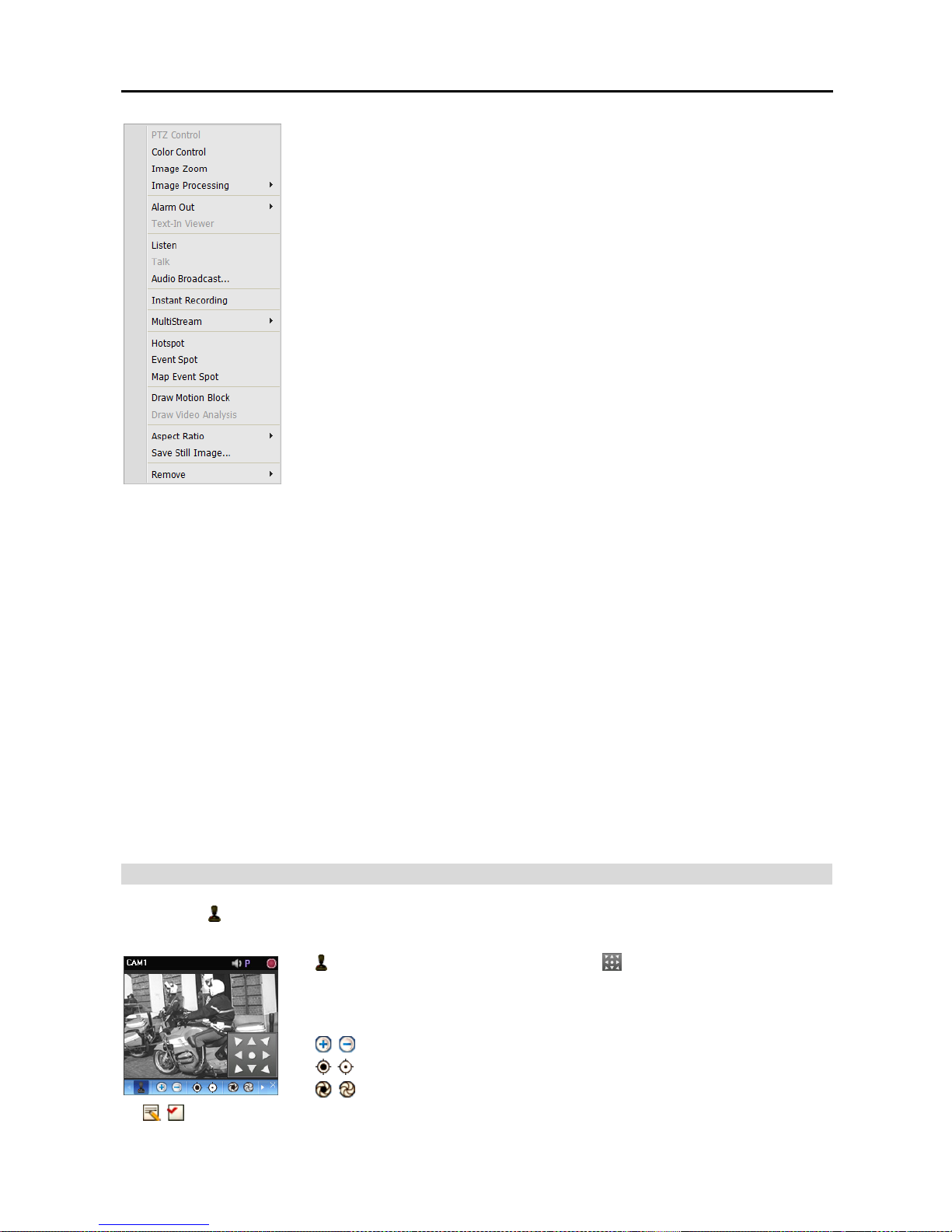
Network Video Recorder
51
PTZ Control, Color Control, Image Zoom, Listen, Talk, Instant Recording:
These function the same as clicking the individual buttons on the control
toolbar. Refer to Control Toolbar (p. 50) for details.
Image Processing: Adjusts the image effect. Refer to Image Effect (p. 53)
for details.
Text-In Viewer: Pops up the text-in viewer window (supported only when a
text-in event is detected). The camera title bar is highlighted in blue when a
text-in event is detected. Refer to Text-In Viewer (p. 53) for details.
Audio Broadcast: Broadcasts audio to all devices in the current Live tab.
Alarm Out: Activates or deactivates alarm out.
MultiStream: Allows you to choose the desired stream if the device is in the
multistream mode for live monitoring (supported only for devices which use
the SiRiS protocol).
Hotspot: Sets up a selected camera screen as a hotspot screen. Refer to
Hotspot Setup (p. 42) for details.
Event Spot: Sets up a selected camera screen as an event spot screen. Refer
to Event Spot Setup (p. 42) for details.
Map Event Spot: Sets up a selected camera screen as a map event spot screen. Refer to Map Event
Spot Setup (p. 43) for details.
Draw Motion Block: Displays the area where motion is detected with red blocks when a motion detection
event occurs for the selected camera (supported only for connection of network video transmitters which
use the SiRiS protocol).
Draw Video Analysis: This is not supported.
Aspect Ratio: Select the proper image aspect ratio.
− Fit to Screen: Displays images by fitting them to the screen size regardless of the aspect ratio.
− Fit to Screen (Aspect Ratio): Displays images by fitting them to the screen size keeping the aspect
ratio. This might cause top and bottom or left and right side of images to be cropped depending on the
screen size. This aspect ratio is not supported and Original Ratio is applied for camera screens that
the following functions are activated: Image Zoom, Hotspot, Event Spot, Draw Motion Block.
− Original Ratio: Displays images by fitting them within the screen size while maintaining their original ratio.
− Half Size (x0.5) to Quadruple Size (x4): Selecting the desired image size displays images in the selected
size. Options are enabled if the selected camera screen can display images in that size.
Save Still Image: Saves the current image on the screen as an image file at its original size.
Remove: Disconnects the current connection.
PTZ Control
Clicking the
(PTZ Control) button on the control toolbar displays the PTZ control toolbar and allows you
to control PTZ. Depending on the PTZ camera specifications, some features may not work.
(Direction Control): Displays or hides the (Direction Control Panel). You
can control the direction of the PTZ camera by clicking the arrow buttons on
the direction control panel or by clicking and dragging the mouse on the camera
screen.
(Zoom In/Out): Zooms the camera lens in or out.
(Focus Far/Near): Focuses on near or far objects.
(Iris Open/Close): Opens or closes the iris of the camera lens.
(Set/View Preset): See PTZ Preset Control (p. 52) for an explanation of this function.
Page 60
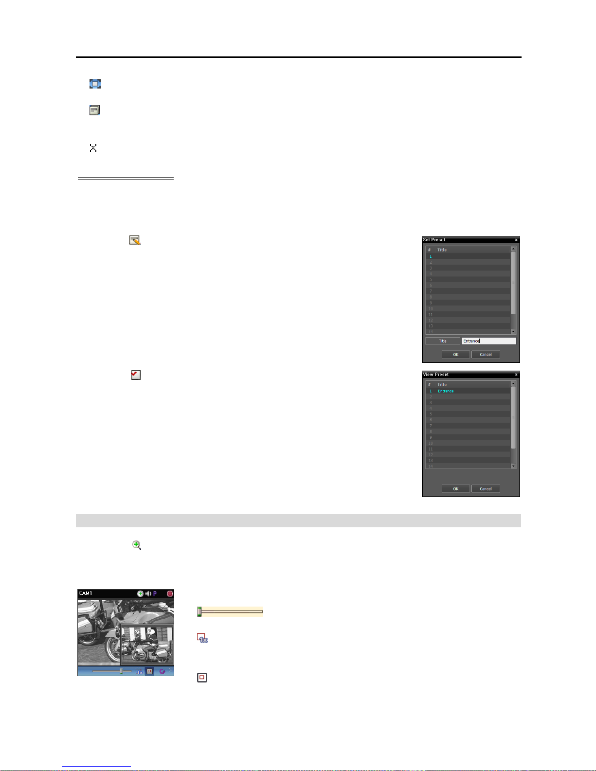
User’s Manual
52
(Auto Focus): Automatically adjusts focus when the image is out of focus after the image is zoomed
in or out (only works for some models of Network Camera connections).
(Advanced Menu): Displays the Advanced Menu window and allows you to use more features that
the PTZ camera supports. Refer to the PTZ camera manufacturer’s manual for details about additional
features.
(Close): Exits the PTZ mode and returns to the control toolbar.
PTZ Preset Control
You can save camera directions as a Presets so that you can move the camera directly to a saved direction.
1. Move the PTZ camera to the desired position.
2. Click the (Set Preset) button on the PTZ control toolbar, and the Set Preset
window appears. Enter a name for the Preset and click the OK button. The
current position is saved as the Preset name.
3. Click the (View Preset) button on the PTZ control toolbar, and the View
Preset window appears. Select the desired Preset, and the PTZ camera moves
to the position of the selected Preset.
Zoom Control
Clicking the
(Image Zoom) button on the control toolbar allows you to zoom in on the current video.
NOTE: “PIP” is an abbreviation of Picture in Picture and describes a smaller screen within a screen.
Dragging the mouse on the camera screen moves the zoomed-in area.
(Slide Bar): Adjusts the enlargement ratio. You can adjust the
enlargement ratio also by using the mouse scroll wheel.
(Actual Size Zoom): Enters the actual size zoom mode. In the actual size
zoom mode, the image is displayed in its original size regardless of the camera
screen size or image’s aspect ratio.
(Zoom Finder): Displays or hides the PIP screen. The rectangle in the PIP
screen indicates the zoomed-in area.
Page 61
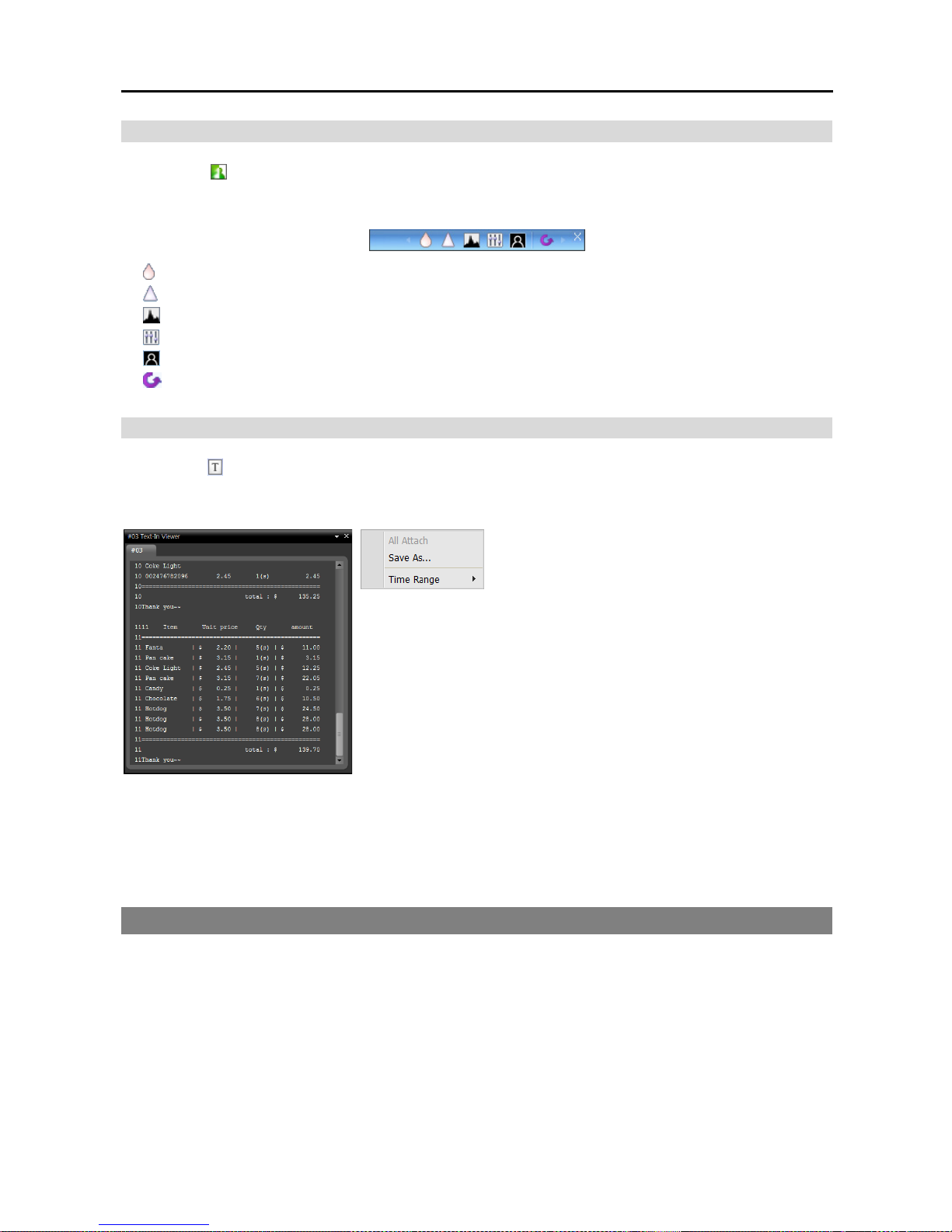
Network Video Recorder
53
Image Effect
Clicking the (Image Effect) button on the control toolbar displays the image effect control toolbar and
allows you to control image effect. This change will be applied to only the video of the SiRiS program and
not to the device.
(
Blur): Blurs the image to reduce noise.
(
Sharpen): Sharpens an image.
(
High-Boost): Increases the brightness and contrast of images.
(
Histogram Equalization): Equalizes the image brightness to make it more natural.
(
Edge Detection): Extracts the image edge.
(
Revert): Cancels the adjustment and reloads the original image.
Text-In Viewer
Clicking the
(Text-In Viewer) button on the control toolbar displays the text-in viewer window and allows
you to check the text-in data in real-time (supported only when a text-in event is detected). The camera
title bar is highlighted in blue when a text-in event is detected.
Clicking the title bar in the Text-In Viewer window
displays a text-in popup menu.
All Attach: Docks all text-in viewer windows in one panel.
Save As: Saves the text-in data as a text file (.txt).
Time Range: Set up the length of time for text-in data to be displayed when a text-in event occurs. You
can check the text-in data in the text-in viewer window within the established time range for the event.
4.4 Controlling Maps
A control toolbar and a screen menu are provided for controlling a map.
Page 62
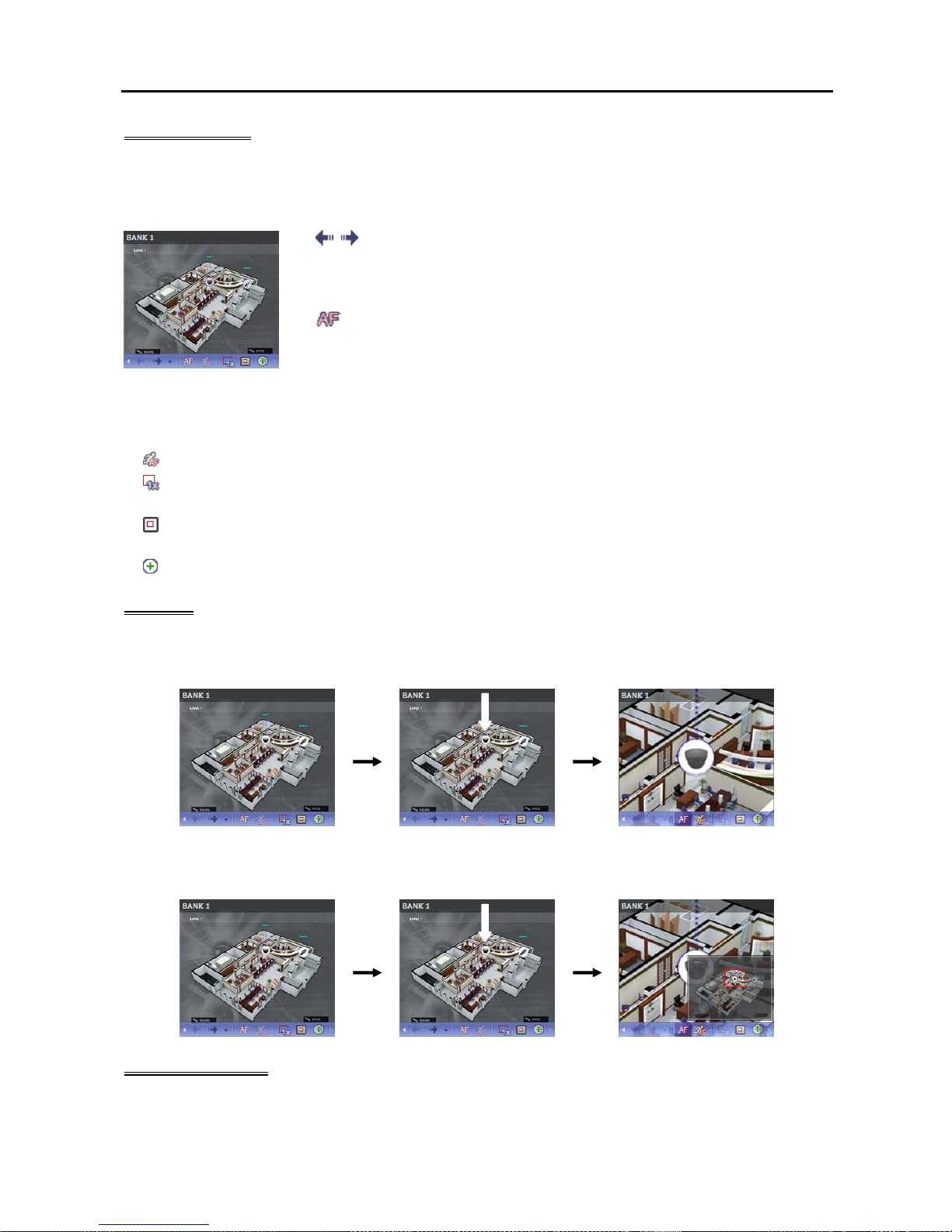
User’s Manual
54
Control Toolbar
When selecting a map and hovering the mouse cursor over the map, the control toolbar is displayed over
that map. The control toolbar allows you to control the selected map. Hovering the mouse cursor over a
button displays a tooltip for the button.
, (Previous Map, Next Map): Moves to the previous or next connected
map of the maps that have been connected to the current map screen. Maps
can be connected by using map link or by selecting a map from the map list
and dragging and dropping it on the current map screen.
(Auto Focusing): Enlarges the area where the event-detected device is placed
when any event is detected. When events are detected in more than one device
at the same time, the canvas is enlarged as much as possible while still displaying
all event-detected devices. When events are detected in more than one device
consecutively, the focusing moves to the later detected event after the preset
time expires. Refer to 3.3 Client, Menu – Preference Settings, Map (p. 39)
for details about the auto focusing setting.
(Focusing Event): Allows you to select a desired event for auto focusing.
(Actual Size (x1)): Displays a map in its original size regardless of the map screen size or canvas’s
aspect ratio.
(Zoom Finder): Displays or hides the PIP screen. The rectangle in the PIP screen indicates the enlarged
area. When set to Auto, the PIP screen is displayed only while a canvas is enlarged.
(Zoom In): Allows you to adjust the enlargement ratio of the canvas.
Example
When Zoom Finder is set to Off;
Map Monitoring
Event Detection
Auto Focusing
When Zoom Finder is set to Auto or On;
Map Monitoring
Event Detection
Auto Focusing
Map Screen Menu
The screen menu is displayed when selecting a map screen and clicking the right mouse button. The screen
menu allows you to control the selected map.
Page 63
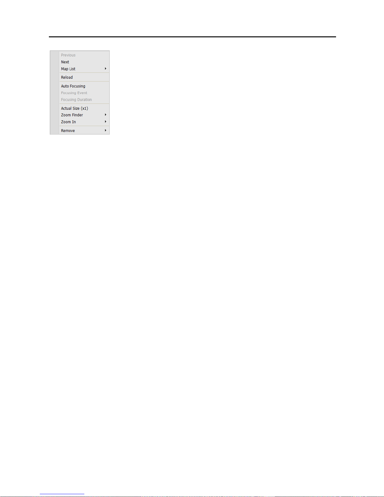
Network Video Recorder
55
Previous, Next, Auto Focusing, Actual Size (x1), Zoom Finder, Zoom In:
These function the same as clicking the individual buttons on the control toolbar.
Refer to Control Toolbar (p. 54) for details.
List: Displays the list of the previous or next connected maps. Selecting a map
from the list moves to the selected map.
Reload: Reloads the connection of the current map.
Focusing Event, Focusing Duration: Allows you to set up auto focusing events
and duration. Refer to 3.3 Client, Menu – Preference Settings (p. 34) for
details.
Remove: Disconnects the current connection.
Page 64

User’s Manual
56
Page 65

Network Video Recorder
57
Chapter 5 — Recording
You can record video from cameras connected to devices registered in the NVR system and SiRiS program
provides three types of recording: Time-Lapse Recording, Event-Based Recording (Event and Pre-Event)
and Instant Recording. During Time-Lapse recording or Event-Based recording, the system performs
recording based on the settings of schedule Presets during the scheduled time. Instant recording can be
manually started or stopped while monitoring video.
When more than one recording mode is set up for the same period, the SiRiS program records video with
the recording settings of the highest priority recording mode. The priority order of recording modes is as
follows: Pre-Event recording (lowest) → Time-Lapse recording or Event recording → Instant recording
(highest). In the same recording mode or between the Time-Lapse recording and Event recording mode,
the schedule higher up the list in the Schedule Setup window has priority over the other schedules. You
can change a schedule’s priority by changing its position in the schedule list.
First, check the following and run the SiRiS Setup program.
Devices should be added to a device group. Refer to Chapter 11 — Device Management (p. 93) for
details.
NOTE: Recording is not supported for DVRs.
5.1 Setting up Recording Schedule
Run the SiRiS Setup program → Select the Recording Schedule menu, and set up the recording
schedule following the procedures below.
NOTES:
The recording function is supported only for the device registered as the admin user.
If the same device is registered on another NVR system or a recording service of SiRiS system, only the
first NVR system or recording server that is connected to the device records video. Once a NVR system
or a recording service connects to the device, other NVR systems or recording servers will not record video
from the device unless the connection of the first NVR system or recording service is released.
The SiRiS program performs recording with the settings of codec, resolution, frame rage and quality set
in the device if the device uses protocols other than SiRiS or ONVIF
TM
Conformance.
If the device uses the ONVIF
TM
Conformance protocol, the SiRiS program performs recording with the
settings of the profile designated in the SiRiS program among preset profiles. You can designate which
profile to use for recording when editing the device settings. Refer to
11.2 Managing Devices, Editing
Device Information
(p. 99) and 11.3 Remote Setup of ONVIF
TM
Conformance Protocol Devices,
Profiles (p. 108) for details.
When the recording speed and resolution set in the SiRiS program are higher than the Frame Rate and
Max. Resolution set on the device, the recording service will record video at the Frame Rate and Max.
Resolution set on the device (four-channel network video transmitters only which use the SiRiS protocol).
If network connection is temporarily lost between the device and the NVR system because of network
problems or NVR system reboot, the device saves video temporarily while the network is down (supported
only for devices which use the SiRiS protocol). When network connection is re-established, the device
transmits the saved video to the NVR system at a time. In this case, video recording during the period
might be made with different settings from those in the recording schedule.
Recording speed might be decreased depending on the network conditions.
Page 66
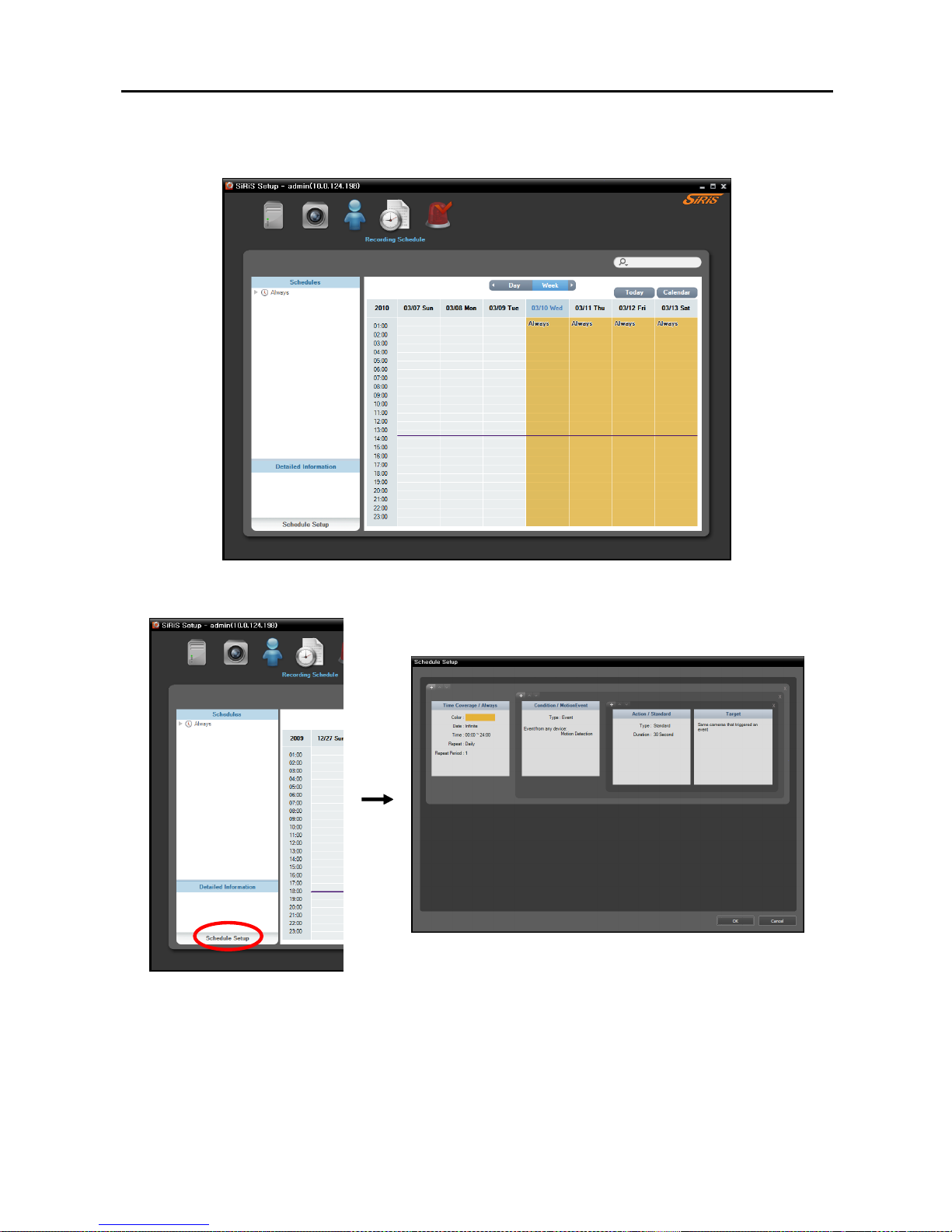
User’s Manual
58
NOTE: Recording might be delayed because of system congestion, and the recording OSD might be displayed
later or for longer than the scheduled time.
Click the Schedule Setup button at the bottom. The Schedule Setup window appears, and schedule
windows are displayed with the current settings for each Preset.
Time Coverage: Sets up the schedule time. You can set up more than one time range. The higher the
schedule position is in the Schedule Setup window, the higher its priority is.
Condition: Sets up the recording type. You can set up more than one recording type for the same recording
period. The higher the schedule position is in the Schedule Setup window, the higher its priority is.
Event related recording types may not be supported depending on the protocol that the device uses and
device model (supported protocols: SiRiS protocol, some versions of the Axis/Panasonic WV (DG)/ONVIF
TM
Conformance protocols). Ask your dealer or distributor for details.
Page 67
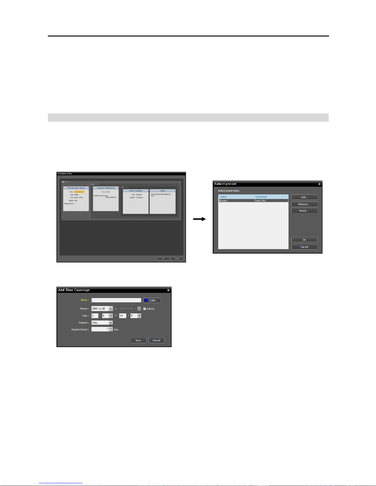
Network Video Recorder
59
Action: Sets up the stream to use for recording (network cameras only) or the recording settings (network
video transmitters only). You can set up more than one recording setting for the same recording type.
This function is supported only for devices which use the SiRiS protocol.
Target: Sets up the cameras to be recorded.
NOTE: In the schedule setup, “Preset” indicates a single setting in which the setting values of Time Coverage,
Condition or Action are saved.
Setting up Time-Lapse Recording
During Time-Lapse recording, the recording service performs recording continuously based on the schedule
settings for the scheduled time (supported only for devices registered on one of recording services).
1. Set up the schedule time by double clicking the Time Coverage schedule window, and then selecting
a desired Preset.
You can add a new Preset or edit a saved Preset by clicking the Add or Modify button. Refer to the
following explanation for setting up a schedule.
Name: Enter the Preset name.
Color: Click the button and select a desired color. The
scheduled time section will be highlighted with the
selected color in the schedule table.
Period: Set up the schedule time. Selecting the Infinite
option causes continuous recording based on the
Condition, Action and Target preset settings without
limiting the period.
Time: Set up the schedule time.
Repeat, Repeat Period: Set up the recording interval and interval period. The recording service
will perform recording at the designated interval during the interval period.
2. Set the recording mode to the Time-Lapse Recording mode by double clicking the Condition schedule
window and selecting a desired Preset of time condition.
Page 68
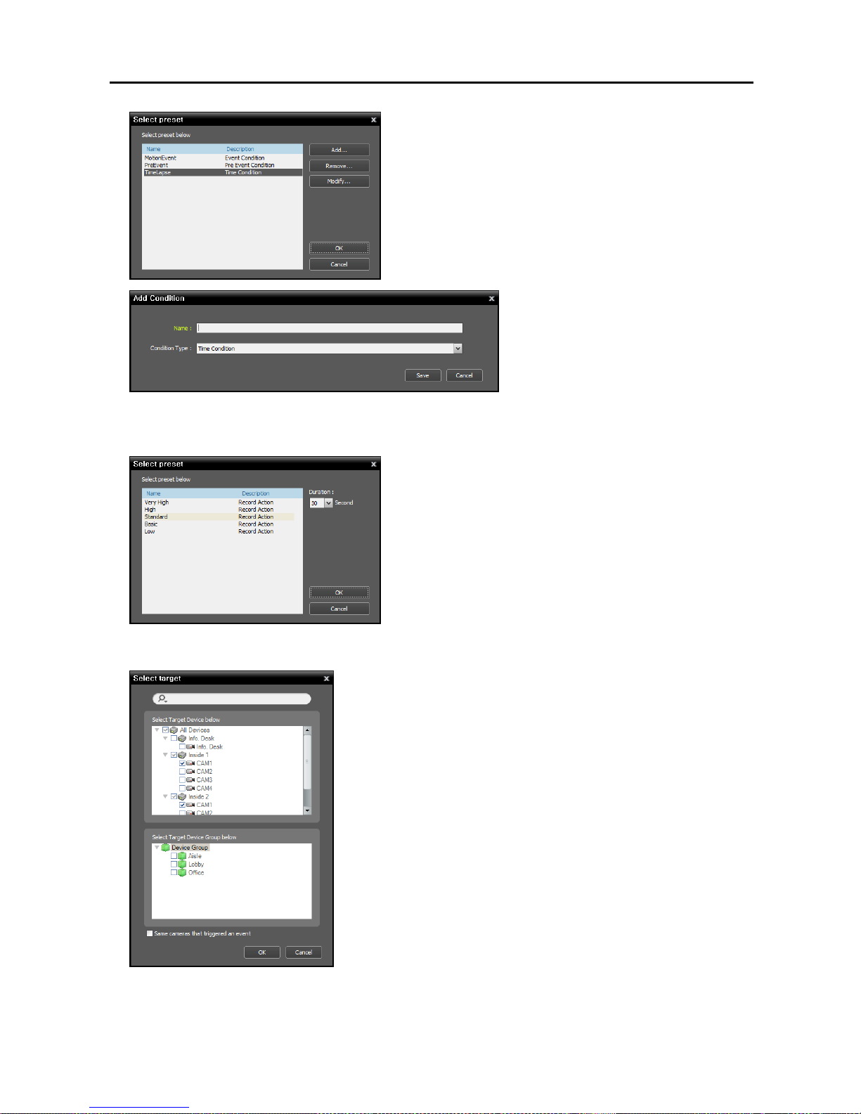
User’s Manual
60
You can add a new Preset or edit a saved Preset by clicking
the Add or Modify button. Clicking the Add or Modify
button displays the following setup screen.
Enter the Preset name and select Time
Condition from the Condition Type list.
3. Double click the Action schedule window and select the desired Preset (supported only for devices which
use the SiRiS protocol).
A stream to use for recording (network cameras only) or a
codec, resolution, frame rate and quality setting values
(network video transmitters only) are allocated to each
Preset. The stream or setting values allocated to each Preset
is different depending on the device. Refer to 11.2
Managing Devices, Editing Device Information (p. 99)
for details.
Duration: This is not supported for time-lapse recording.
4. Select the cameras to be recorded after double clicking the Target schedule window.
Select cameras from the device list to record video or select device
groups from the device group list. The Same cameras that
triggered an event option is not supported during Time-Lapse
recording.
Page 69
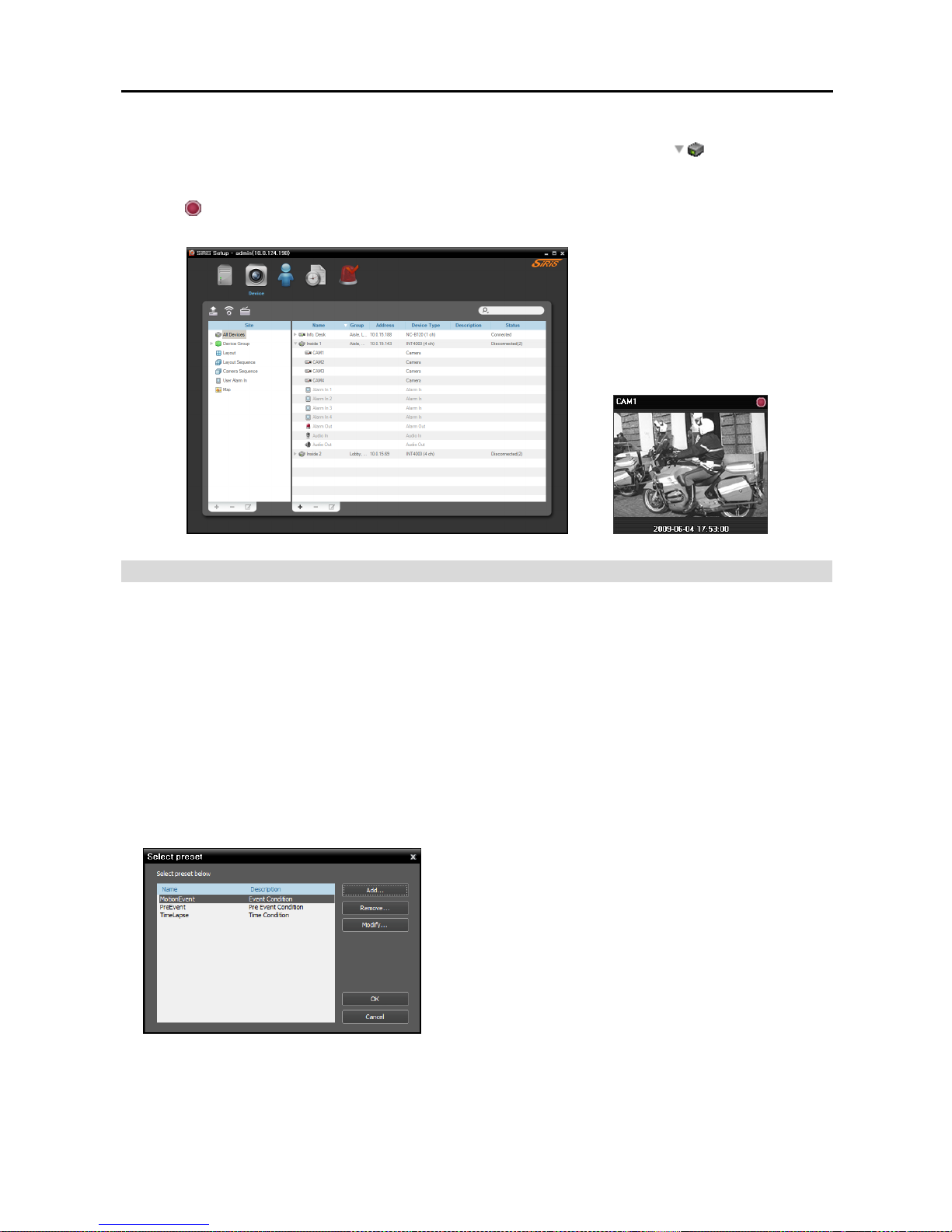
Network Video Recorder
61
5. You can check the recording status in the Device menu. Click All Devices in the Site panel and all
registered devices are displayed in the Site List panel. Click the arrow button (
) beside the device
name, and check the status (Record: During Time-Lapse recording or Event-Based recording, Panic:
During Instant recording, Idle: Ready to record). The Time-Lapse Recording or Event-Based Recording
OSD (
) is displayed in the upper right corner of the camera screen of the Live screen in the SiRiS Client
program.
Setting up Event-Based Recording
During Event or Pre-Event recording, the recording service records video based on the event detection for
the scheduled time (supported only for devices registered on one of recording services). Event related
functions may not be supported depending on the protocol that the device uses and device model (supported
protocols: SiRiS protocol, some versions of the Axis/Panasonic WV (DG)/ONVIF
TM
Conformance protocols).
Ask your dealer or distributor for details.
1. Set the schedule time by double clicking the Time Coverage schedule window, and then selecting a
desired Preset. The way to set up the schedule time for Event or Pre-Event recording is identical to the
way to set up for Time-Lapse recording. Refer to Setting up Time-Lapse Recording (p. 59) for details.
2. Set up the recording mode to Event Recording or Pre-Event Recording by double clicking the Condition
schedule window. Then select a desired Preset of event or pre-event condition.
You can add a new Preset or edit a saved Preset by clicking
the Add or Modify button. Clicking the Add or Modify
button displays the following setup screen.
Page 70
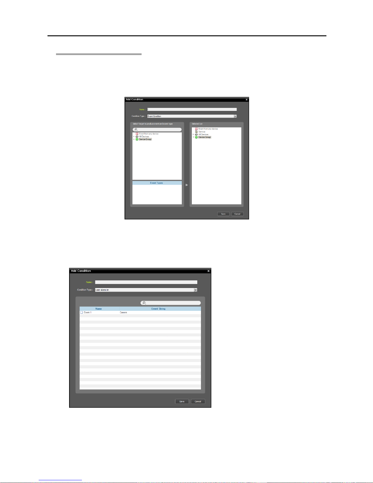
User’s Manual
62
Event Recording Condition
The recording server records video when predefined events are detected. This function may not be
supported depending on the protocol that the device uses and device model (supported protocols: SiRiS
protocol, some versions of the Axis/Panasonic WV (DG)/ONVIF
TM
Conformance protocols). Ask your
dealer or distributor for details.
Name: Enter the Preset name.
Condition Type: Select an event type.
− User Alarm In: Records video of a device when a user alarm in event is detected for the device in
the SiRiS program. Refer to Chapter 11 — Device Management, User Alarm In Event Setup
(p. 94) for details about registering the user alarm in event.
Name: Displays a list of user alarm in
events registered on the administration
service.
Event String: Displays the event string
that triggers a user alarm in event.
Select a user alarm in event to record.
− Event Condition: Records video when specific events are detected in devices.
Page 71
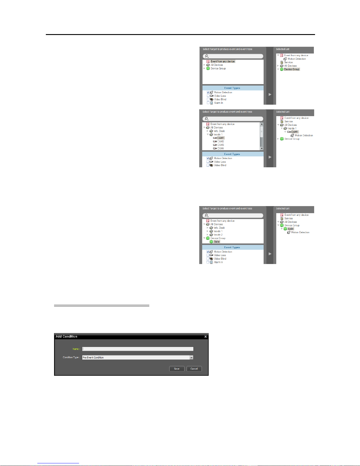
Network Video Recorder
63
Event from any device: Select to record video
when user-defined types of events are detected.
Click Event from any device, and the list of
event types is displayed in Event Types below
→ Select the desired event types, and the selected
event types are added to the list under Event from
any device on the right.
All Devices: Select to record video when user-
defined types of events are detected from the
selected device or camera.
Click All Devices, and the list of registered
devices and cameras is displayed → Under All
Devices, click a device or camera to trigger
Event recording, and the list of event types
supported by the device or camera is displayed
in Event Types below → Select the desired
event types, and the selected event types are added
along with the selected device or camera to the
list under All Devices on the right.
Device Group: Select to record video when
the user-defined types of events are detected in
the selected device group.
Click Device Group, and the list of registered
device groups is displayed → Under Device
Group, click a device group to trigger Event
recording, and the list of event types is displayed
in Event Types below → Select the desired
event types, and the selected event types are added
along with the selected device group to the list
under Device Group on the right.
Pre-Event Recording Condition
The recording service records video prior to event detection when predefined events are detected (supported
only for devices which use the SiRiS protocol).
Enter the Preset name and select Pre
Event Condition from the Condition
Type list.
3. Double click the Action schedule window, and then selecting a desired Preset (supported only for devices
which use the SiRiS protocol).
Page 72
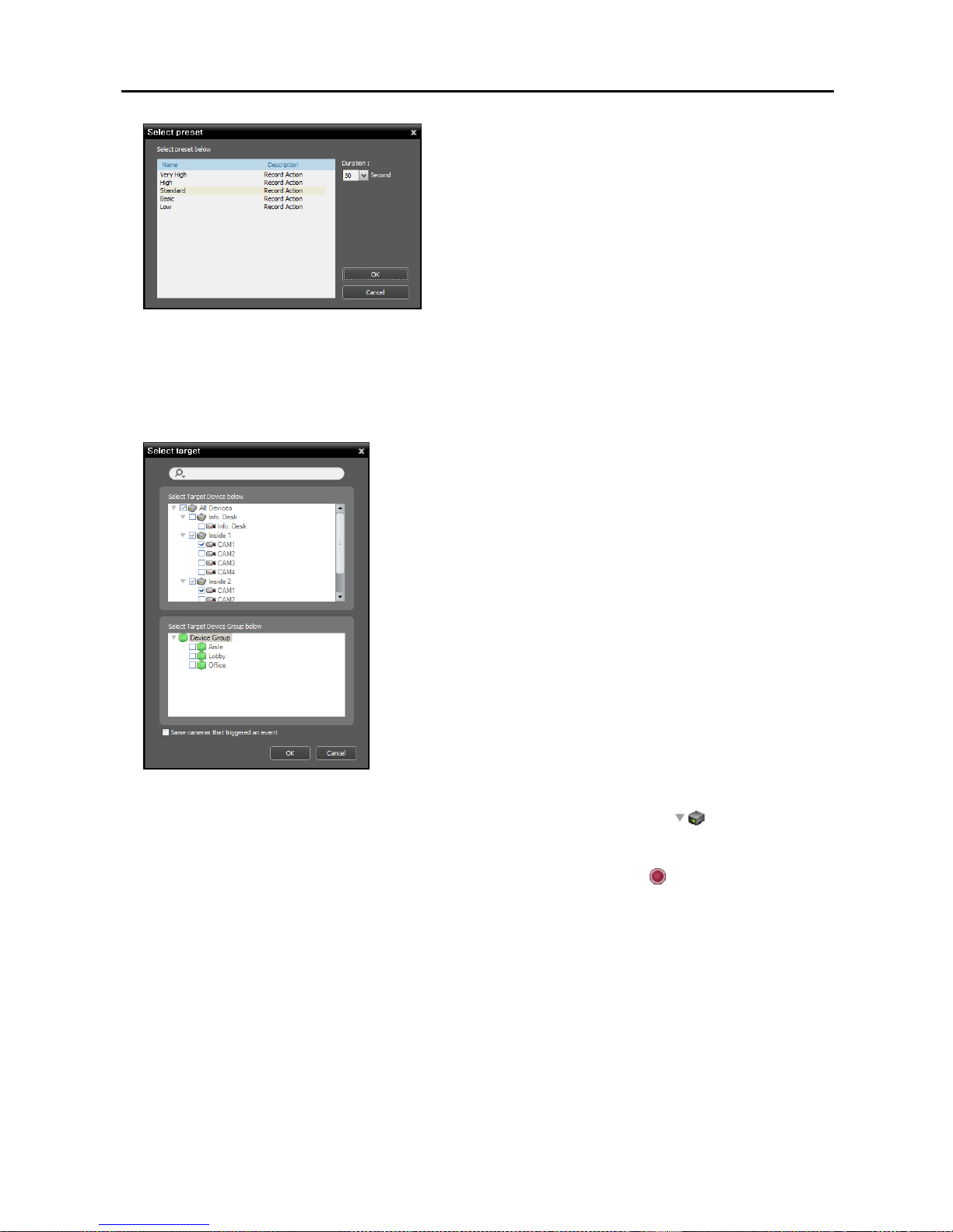
User’s Manual
64
A stream to use for recording (network cameras only) or a
codec, resolution, frame rate and quality setting values
(network video transmitters only) are allocated to each
Preset. The stream or setting values allocated to each Preset
is different depending on the device. Refer to 11.2
Managing Devices, Editing Device Information (p. 99)
for details.
Duration: Set up the duration (maximum of 60 seconds)
of recording when a predefined event is detected. For
Event recording, the system records video for the duration
from the time an event is detected. For Pre-Event
recording, the system records video for the duration prior
to event detection.
4. Select the cameras to record after double clicking the Target schedule window.
Select cameras from the device list or device groups from the device
group list from which to record video whenever any predefined event
is detected. Selecting the Same cameras that triggered an event
option records video only from the camera where the predefined event
is detected (not supported for alarm-in events and audio detection
events). The Same cameras that triggered an event option is
not supported for Pre-Event recording.
5. You can check the recording status in the Device menu. Click All Devices in the Site panel and all
registered devices are displayed in the Site List panel. Click the arrow button (
) beside the device
name, and check the status (Record: During Time-Lapse recording or Event-Based recording, Instant
Recording: During Instant recording, Idle: Ready to record, Not Use: Camera disabled, Video Loss:
On video loss). The Time-Lapse Recording or Event-Based Recording OSD (
) is displayed in the upper
right corner of the camera screen of the Live screen in the Client program.
Page 73
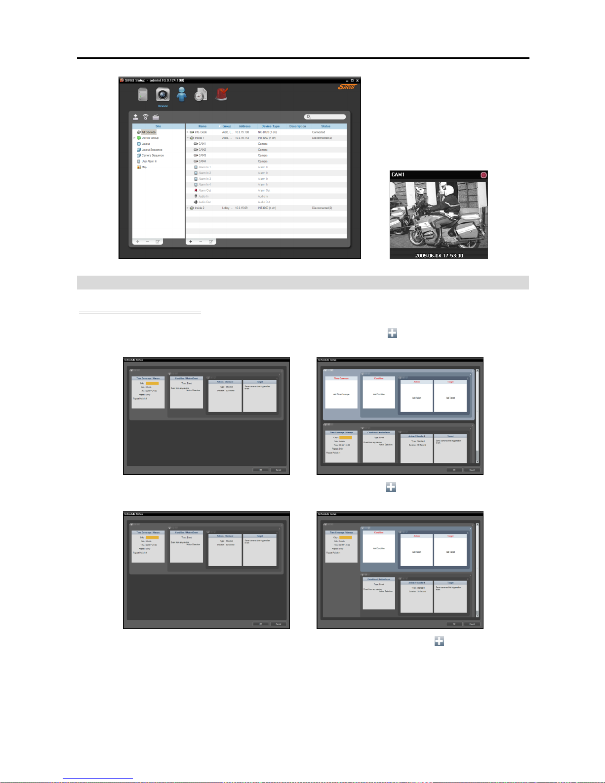
Network Video Recorder
65
Managing Schedule
Adding a New Schedule
Adding a new schedule with a different time range: Clicking the
button in the upper left corner
of the Time Coverage schedule window allows you to add a new schedule with a different time range.
Adding a new schedule with the same time range: Clicking the button in the upper left corner
of the Condition schedule window allows you to add a new schedule with the same time range.
Adding a new schedule with the same time range and target: Clicking the button in the upper
left corner of the Action schedule window allows you to add a new schedule with the same time range
and target.
Page 74
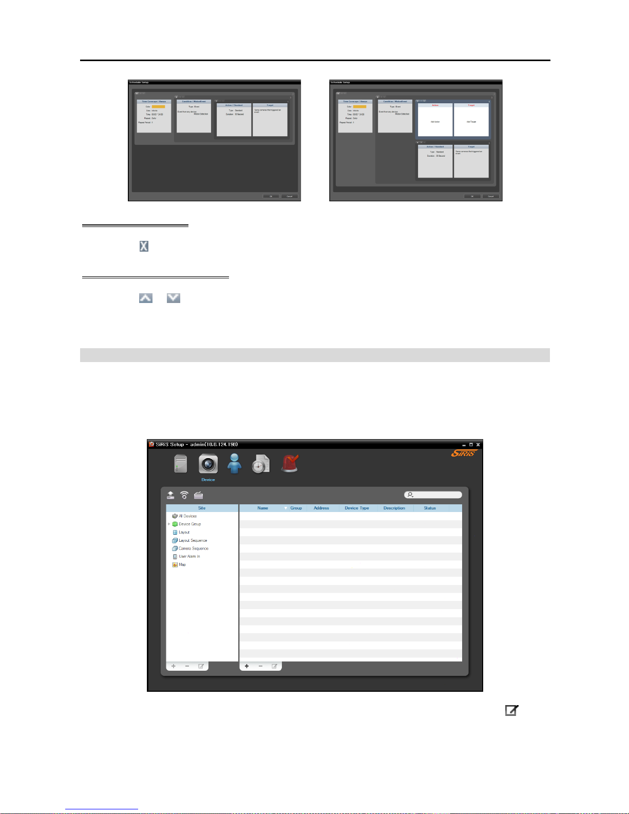
User’s Manual
66
Deleting a Schedule
Clicking the
button in the upper right corner of any schedule window deletes the schedule.
Changing Schedule Priority
Clicking the
or button in the upper left corner of each schedule window changes the priority of the
schedules. The higher the schedule position is in the Schedule Setup window, the higher its priority is.
The Pre-Event Recording has no priority over the Time-Lapse Recording or Event Recording.
Setting up Instant Recording
Instant recording can be manually started or stopped while monitoring video (supported only for devices
registered on one of recording services).
1. Select the Device menu.
2. Click a device group in the Site panel and then click a device in the Site List panel. Clicking the
button
at the bottom of the Site List panel, or clicking the right mouse button displays the device menu.
Page 75
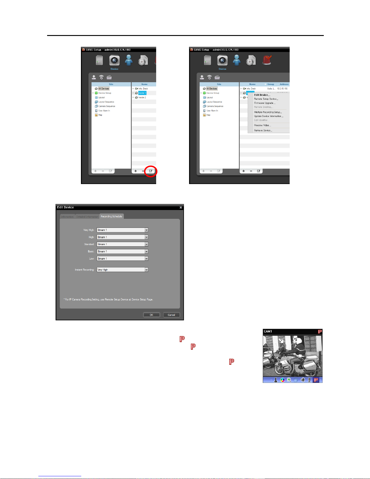
Network Video Recorder
67
OR
3. Select Edit Device from the device menu. Select the Recording Schedule tab.
Instant Recording: Select a Preset to use for
instant recording. Refer to 11.2 Managing
Devices, Editing Device Information (p. 99)
for details about setting up the Preset.
4. Run the SiRiS Client program. Select a camera screen (on the Live screen) on
which video to record is displayed and click the
(Instant Recording) button
on the control toolbar. The Instant Recording OSD (
) is displayed at the top
right corner of the camera screen, and the system starts recording with the
Preset selected in the Recording Schedule tab above. Clicking the
(Instant
Recording) button again stops recording. Recording might be delayed because
of system congestion, and the recording OSD might be displayed later or for
longer than the scheduled time.
Page 76

User’s Manual
68
Page 77
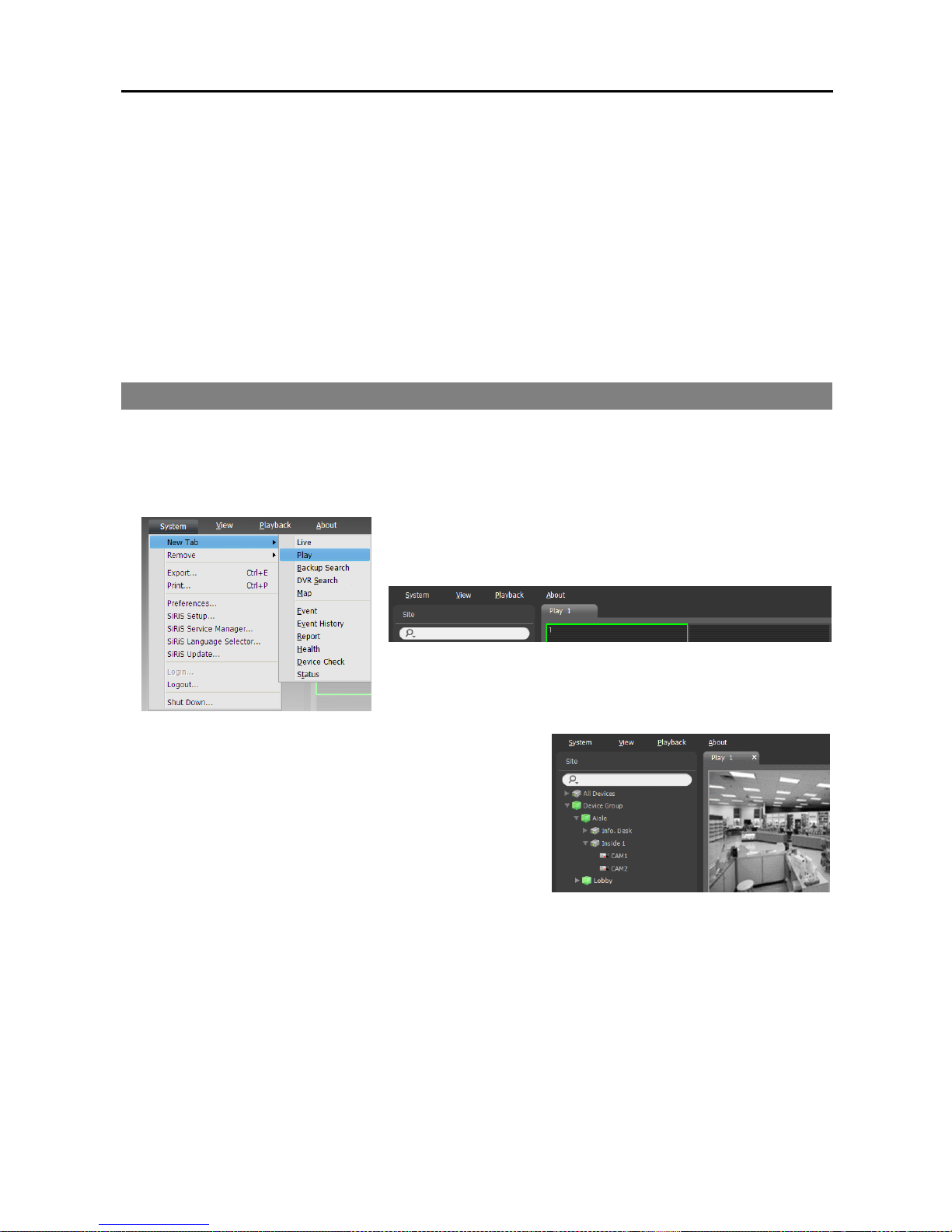
Network Video Recorder
69
Chapter 6 — Recorded Video Playback & Exportation
You can play back recorded video or export recorded video as a video clip.
First, check the following.
Devices should be added to a device group. Refer to Chapter 11 — Device Management (p. 93) for
details.
There should be recorded data in the allocated storage. Refer to Chapter 13 — Storage Management
(p. 113) for details.
6.1 Playing back Recorded Video
1. Search and playback of video recorded in the NVR system are supported in the Play panel (maximum 4)
and search and playback of video recorded in DVRs or SD (SDHC) memory cards inserted to network
cameras using the SiRiS protocol are in the DVR Search panel (maximum 4). If the Play or DVR Search
tab is not on the tab panel, go to the System menu, click New Tab and then Play or DVR Search.
2. Click the Play or DVR Search tab on the tab panel → Select
a site to connect to from the Site list and drag and drop it
on the Play or DVR Search screen. Recorded video from
the selected site is displayed on the screen. You can move
a camera screen to the desired location on the Play or DVR
Search screen without stopping the current playback while
playing back video. Select a camera screen and drag and
drop it on the desired location.
If a layout is registered on the NVR system, you can play video in the layout format by selecting a
desired layout from the Layout list and dragging and dropping it on the Play or DVR Search screen.
Refer to 4.1 Monitoring Video, Layout Monitoring, Registering Layouts (p. 43) for details about
the registration of a layout.
NOTES:
The system performance might seriously deteriorate when simultaneously monitoring or playing back video
with 1280x720 or higher resolution on more than one camera screen.
A “layout” in this document refers to a screen organization created by arranging specific cameras in a
specific screen format.
Page 78
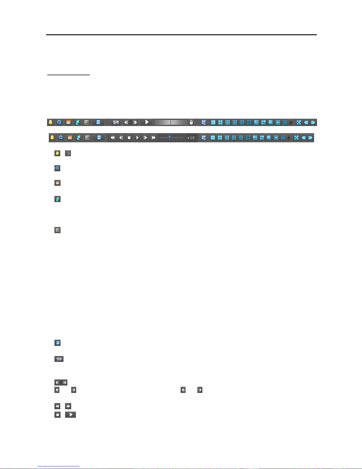
User’s Manual
70
3. A panel toolbar, a timetable, a control toolbar and a screen menu are provided for playing back recorded
video.
Panel Toolbar
The toolbar at the bottom of the panel allows you to search and play back recorded video.
NOTE: The toolbar may be different and some functions below may not be supported, depending on the
specifications and version of the device.
/ (Event Search/Time-Lapse Search): Switches search mode between event search and time-lapse
search. Refer to Timetable/Event List (p. 71) for details.
(Search Filter): Sets search conditions for event search. Refer to the device user manual for details
about the search condition.
(Calendar): Searches video for a specific date. Selecting a date displays the recorded data for that date
in the timetable. The dates containing recorded images are enabled in the calendar.
(Move to): Searches video for a specific time.
− Go To: Displays a time setup window. Entering a specific time moves to the image for that time.
− Move First: Moves to the first recorded image in the data displayed in the timetable.
− Move Last: Move to the last recorded image in the data displayed in the timetable.
(Additional Menu): Displays a menu.
− Save Still Image: Saves the current image on the screen as an image file at its original size.
− Export Image File, Print Image: Exports or prints the images currently displayed on the screen.
− Export Panorama Screen: Exports the images currently displayed on the screens.
− Removed Devices: Allows you to search for a removed device and play back video from that device
if video was recorded in the NVR system before the device was removed (supported only for the Play
panel).
− Select Segment: Allows you to select a video segment when the DVR’s time and date have been reset
to a time that is earlier than previously recorded video and there is more than one video segment in the
same time range due to time overlap (supported only for DVRs which provide the hour segments timetable)
− Data Source: Selects the data source to be searched (supported only for the DVR Search panel).
Search on Local: Searches recorded data on primary storage installed in the DVR.
Search on Archive: Searches archived data on backup storage installed in the DVR.
Search on Other: Searches recorded or archived data on Storage used for another DVR then installed
in the DVR. This may not be supported, depending on the specifications and version of the DVR.
(Export Video File): Exports recorded video as a self-player file (.exe) or an AVI file (.avi). Refer
to 6.2 Exporting Recorded Video (p. 75) for details.
(Snapshot on Motion Event – Play panel): Displays snapshot of images recorded during the event-
based recording (event and pre-event) in the Play panel. Refer to Snapshot on Motion Event (p. 73)
for details.
(Step Playback): Moves the video forward or backward based on the setting displayed between the
and buttons. Clicking the arrow between the and buttons allows you to change the interval the
video moves.
/ (Fast Backward/Fast Forward): Plays back recorded video fast backward or fast forward.
/ (Stop/Play): Stops or plays recorded video on the screen.
Page 79
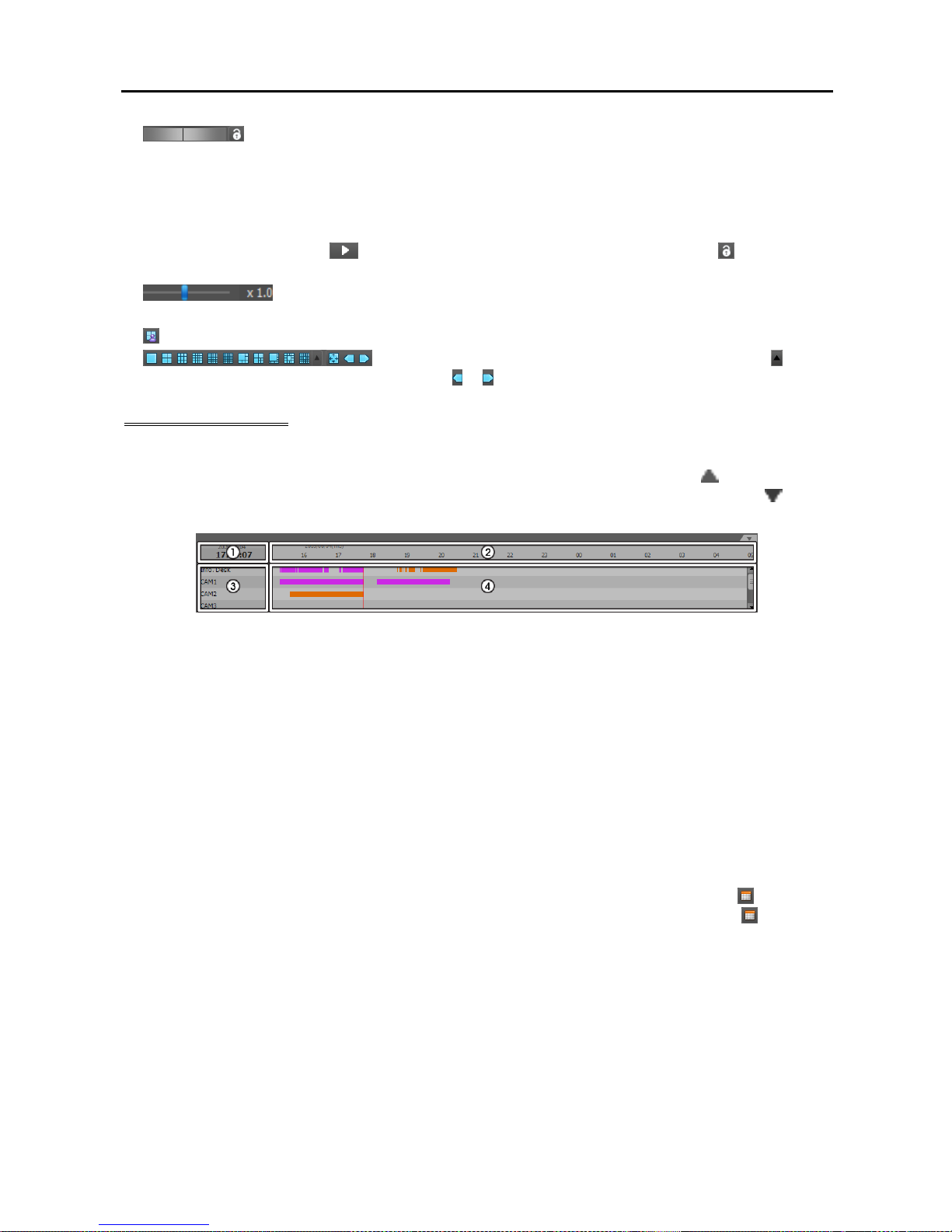
Network Video Recorder
71
(Jog Shuttle – Play panel): You can adjust the playback direction and speed by using the
jog shuttle. The vertical line in the jog shuttle indicates the current playback direction and speed. Video
is played backward when the vertical line is to the left of center and video is played back forward when
the vertical line is to the right of center. The farther the position is from the center, the faster video is
played back. Clicking the vertical line and dragging it to the desired position on the jog shuttle and holding
it plays video at a constant speed. Releasing the mouse button causes the vertical line to return to the
center position. Clicking the
(Play) button plays video at normal speed. Clicking the (Shuttle Lock)
button and dragging and dropping the vertical line to a desired position fixes the vertical line in that position.
(Jog Shuttle – DVR Search panel): You can adjust the playback speed by using the
jog shuttle. The vertical line in the jog shuttle indicates the current playback speed.
(Save to User Layout): Saves the current screen format.
(Screen Format): Changes the screen format. Clicking the button
displays additional screen formats. Clicking the or button moves to the previous or next camera groups.
Timetable/Event List
Time-Lapse Search Mode: When in the time-lapse search mode, the timetable is displayed at the bottom
of the screen and it displays the recording information for each camera. Clicking the
button in the top
right corner of the timetable displays the recording information for all cameras. Clicking the
button
displays the recording information for the selected camera on the screen.
NOTE: The timetable will differ depending on the model of the device.
① Current Playback Date/Time: Indicates the video time for the current playback location on the
timetable.
② Recorded Period: Displays the date and time period of the recorded data. Clicking anywhere in the
empty space and dragging it to the left or right moves to the earlier or later date or time. Scrolling
the mouse wheel while holding the Ctrl key on the keyboard zooms in and out the time section.
③ Camera Title: Displays the camera title.
④ Recorded Data: Displays the recorded data by time in one minute or one hour segments.
Minute Segments Timetable (all devices except some DVR models)
− Red vertical line: Indicates the current playback location of video on the timetable. Clicking the
mouse on the desired time displays the first image recorded within the time.
− Yellow separation line: Separates segments when time overlap occurs. In this case, the recorded
data in the time range located after the separation line is the latest. Clicking the
(Calendar)
button in the Play panel allows you to move to a specific segment directly (Click the (Calendar)
button → Select a date → Select a segment → The first image recorded within the selected segment
is displayed on the screen).
− The color of the bar: Indicates different recording modes (Navy blue for Time-lapse, Pink for Event,
Purple for Pre-event, Sky blue for Instant Recording and Orange for Irregular recording caused
by temporary disconnection from the device).
Hour Segments Timetable (some DVR models only)
− Yellow color bar: Indicates the current playback location of video on the timetable.
Page 80
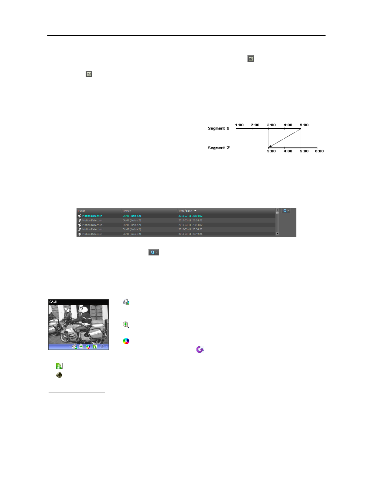
User’s Manual
72
− Pink color bar/Gray color bar: Indicates the segment of video that is currently displayed/not
displayed on the screen when time overlap occurs. Clicking the
(Additional Menu) button
in the DVR Search panel allows you to change the segment to be displayed on the screen (Click
the (Additional Menu) button → Select the Select Segment menu → Select a desired segment
→ The first image recorded within the selected segment is displayed on the screen).
NOTE: The NVR system or DVR’s time and date have been reset to a time that is earlier than previously
recorded video, it is possible that there is more than one video segment in the same time range due to time
overlap. In this case, you can individually play video recorded during the overlapping time by selecting a
segment.
For example, when the NVR system or DVR has recorded
video from one to five o’clock and the user changes the time
backward from five to three o’clock and then continues
recording until six o’clock, there will be two segments from
three to five o’clock.
Event Search Mode: When in the event search mode, the event list is displayed at the bottom of the screen
as follows:
− Play panel: Events only that were recorded during Event recording.
− DVR Search panel: All events when searching for video recorded in a DVR, and events only that occurred
while recording on an SD (SDHC) memory card is enabled when searching for video recorded on an
SD (SDHC) memory card.
Clicking an event from the list displays the event-recorded video on the screen if the events were recorded
during Event recording. Clicking the
button in the top right corner of the event list displays next results.
Control Toolbar
The control toolbar is displayed over a selected camera screen when hovering the mouse cursor over the camera
screen. Hovering the mouse cursor over each button displays a tooltip for the button.
(Object/Motion Search): Allows you to search for changes or motion in
recorded images in the NVR system. Refer to Object/Motion Search (p. 73)
for details.
(Image Zoom): Zooms in on the image. Refer to Zoom Control (p. 74) for
details.
(Color
Control
): Adjusts the brightness, contrast, saturation and hue of the
current video. Clicking the
button cancels the adjustment and reloads the
original image. This change will not be applied to the recorded video.
(Image Effect): Adjusts the image effect. Refer to Image Effect (p. 75) for details.
(Audio Play): Plays audio when playing back video that has recorded audio (single-screen format only).
Play Screen Menu
The screen menu is displayed when selecting a camera screen and clicking the right mouse button.
Page 81
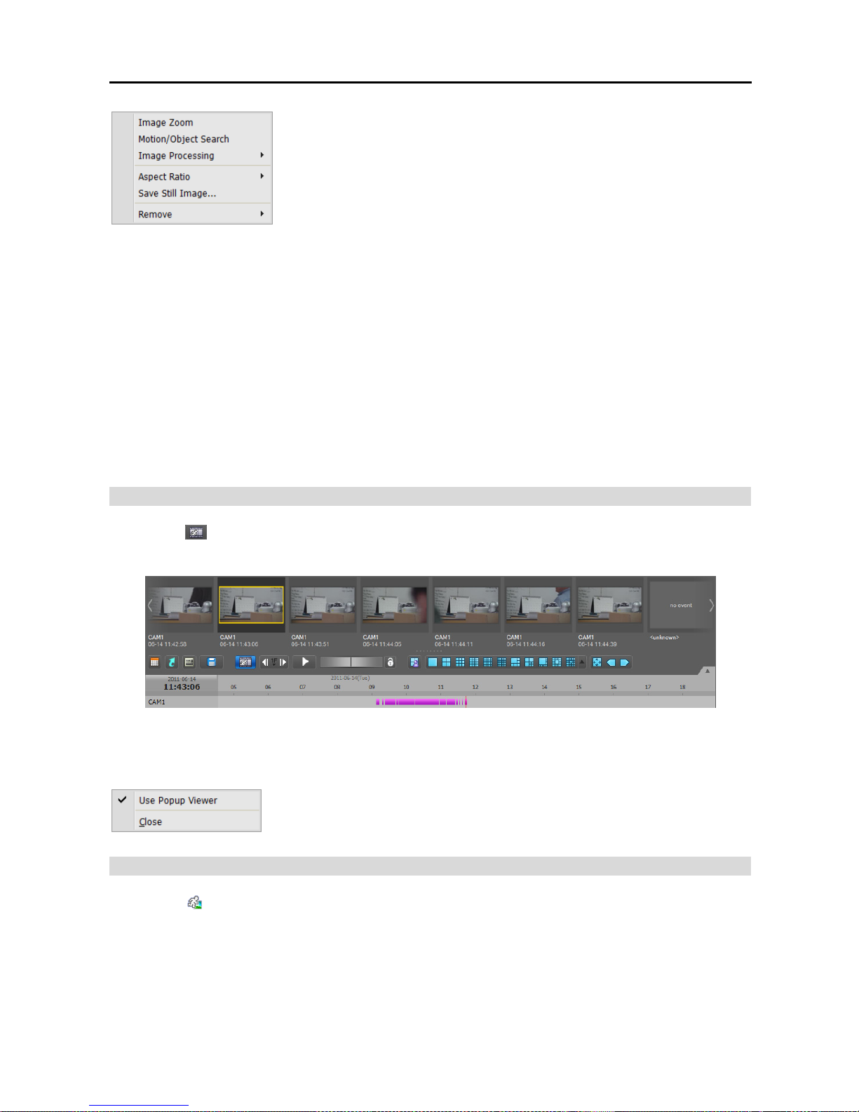
Network Video Recorder
73
Image Zoom: Functions as the same as clicking the button in the control
toolbar. See Control Toolbar (p. 72) for details.
Object/Motion Search: Allows you to search for changes or motion in
the recorded images in the NVR system. Refer to Object/Motion Search
(p. 73) for details.
Image Processing: Enhances playback images. Refer to Control Toolbar
(p. 72) for details.
Aspect Ratio: Select the proper image aspect ratio.
− Fit to Screen: Displays images by fitting them to the screen size regardless of the aspect ratio.
− Fit to Screen (Aspect Ratio): Displays images by fitting them to the screen size keeping the aspect
ratio. This might cause top and bottom or left and right side of images to be cropped depending on the
screen size. This aspect ratio is not supported and Original Ratio is applied for camera screens that
the following function is activated: Image Zoom.
− Original Ratio: Displays images by fitting them within the screen size while maintaining their original
ratio.
− Half Size (x0.5) to Quadruple Size (x4): Selecting the desired image size displays images in the
selected size. Options are enabled when the selected camera screen can display images in that size.
Save Still Image: Saves the current image on the screen as an image file at its original size.
Remove: Disconnects the current connection.
Snapshot on Motion Event
Clicking the
(Snapshot on Motion Event) button on the panel toolbar displays snapshots of images recorded
during the event-based recording (event and pre-event) in the Play panel.
The timetable displays the recording information of the selected snapshot. Clicking anywhere on the recorded
data in the timetable displays a snapshot of the selected time. Hovering the mouse cursor over each snapshot
displays a popup viewer screen above the snapshot.
Use Popup Viewer: Enables display of the popup viewer screen.
Object/Motion Search
Clicking the
(Object/Motion Search) button on the control toolbar displays the object/motion search panel
at the bottom and allows you to search for changes or motion in recorded images in the NVR system.
Page 82
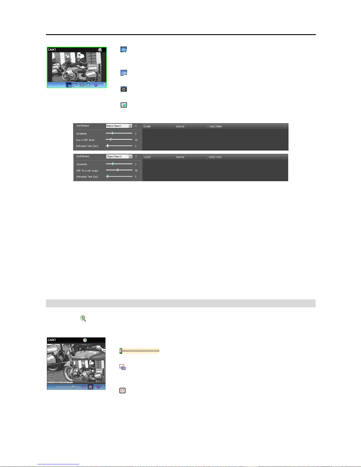
User’s Manual
74
(Draw Search Zone): Allows you to define the area to search for changes
or motion on the camera screen by dragging the mouse. The search zone is
displayed with red blocks.
(Erase Search Zone): Allows you to erase the search zone set on the camera
screen by dragging the mouse.
(Set Ref. Image): Sets the image currently displayed on the camera screen
as a reference image for change detection (Object Search only).
(View Ref. Image): Displays or hides a PIP screen with the reference image
(Object Search only).
Find Method: Selects a search method.
− Motion Search: Searches for images with changes in the Search Zone between two consecutive images
(for example, when there was movement).
− Object Search: Searches for images with changes which last for the Activation Time in the Search
Zone when compared to the reference image (for example, when an object disappeared).
Sensitivity: Sets the sensitivity of the change detection. The higher the number is, the more sensitive
it is.
Num of diff. block: Sets the minimum number of blocks that must be activated to be considered as a
change (Motion Search only).
Diff. % to ref. image: Sets the minimum proportion (%) of blocks that must be activated to be considered
as a change (Object Search only).
Activation Time: Sets the duration that the change must last to be considered as a change. If a change
is detected but does not last as long as the Activation Time, the change is not considered as a change.
Zoom Control
Clicking the
(Zoom) button on the control toolbar allows you to zoom on the current video.
NOTE: “PIP” is an abbreviation of Picture in Picture and indicates the smaller screen within a screen.
Dragging the mouse on the camera screen moves the zoomed-in area
(Slide Bar): Adjusts the enlargement ratio. You can adjust the
enlargement ratio also by using the mouse scroll wheel.
(Actual Size Zoom): Enters the actual size zoom mode. In the actual size
zoom mode, the image is displayed in its original size regardless of the camera
screen size or image’s aspect ratio.
(Zoom Finder): Displays or hides the PIP screen. The rectangle in the PIP
screen indicates the zoomed-in area.
Page 83
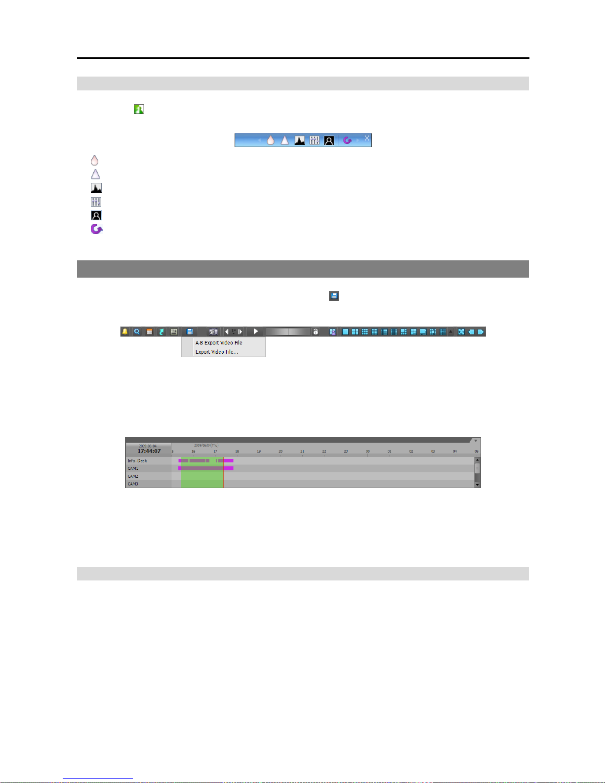
Network Video Recorder
75
Image Effect
Clicking the (Image Effect) button on the control toolbar displays the image effect control toolbar and
allows you to control image effect. This change will not be applied to the recorded video.
(
Blur): Blurs the image to reduce noise.
(
Sharpen): Sharpens an image.
(
High-Boost): Increases the brightness and contrast of images.
(
Histogram Equalization): Equalizes the image brightness to make it more natural.
(Ed
ge Detection): Extracts the image edge.
(
Revert): Cancels the adjustment and reloads the original image.
6.2 Exporting Recorded Video
You can export recorded video to USB devices. Click the
(Export Video File) button on the toolbar at
the bottom of the panel, and the export menu is displayed.
A-B Export Video File: Sets up the section of video to be exported by using the timetable. Select A-B
Export Video File from the export menu. Click the starting point in the timetable and drag to the ending
point. The Export Video File window appears and allows you to export video of the selected period
as a self-player file (.exe) or an AVI file (.avi). Refer to Exporting as a Self-Player File (p. 75) and
Exporting as an AVI File (p. 78) for details.
Export Video File: Sets up the section of video to be exported by entering the date and time manually.
Select Export Video File from the export menu. The Export Video File window appears and allows
you to export video for the period as a self-player file (.exe) or an AVI file (.avi). Refer to Exporting
as a Self-Player File (p. 75) and Exporting as an AVI File (p. 78) for details.
Exporting as a Self-Player File
The recorded video is exported as a self-player file (.exe).
Page 84
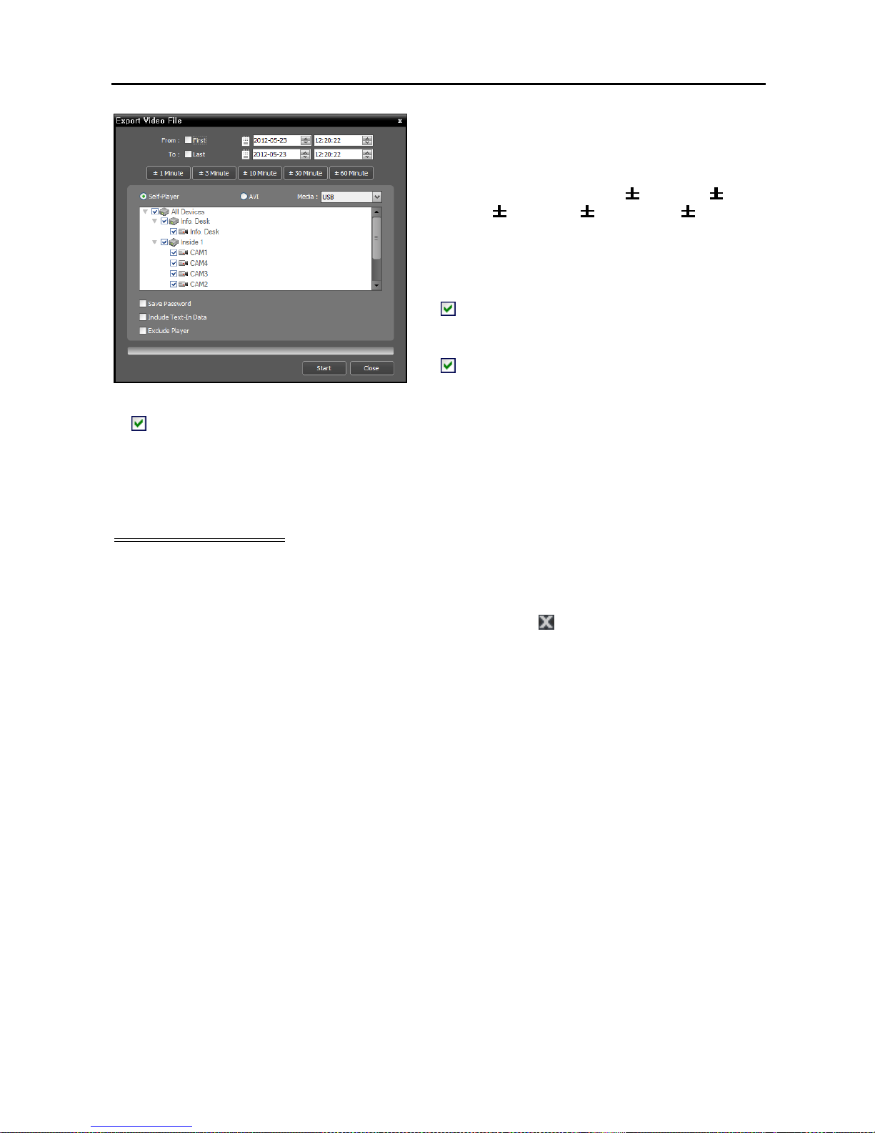
User’s Manual
76
From, To: Enter the date and time of video to export.
Selecting First sets the date and time to the date and
time of the first recorded video. Selecting Last sets
the date and time to the date and time of the last
recorded video. Clicking the
1 Minute,
3
Minute,
10 Minute, 30 Minute or 60 Minute
button increases or decreases the time by the selected
amount from the time selected on the timetable.
Self-Player, AVI: Select Self-Player.
Media: Select a storage device.
Save Password: Set up a password for playing
back the exported video. You will be asked to enter
the password to initiate the Player program.
Include Text-In Data: Includes text-in data when
saving video if the video was recorded with text-in
data (supported only for the DVR Search panel).
Exclude Player: Saves the recorded data without including the Self-Player program (supported only
for the DVR Search panel). The file size will be smaller, and it will take less time to save, but you will
need to run the Self-Player program (ClipPlayer.exe) which is provided in the SiRiS Client program
installation folder (\Client\selfplayer) to play the saved file. This may not be supported, depending on
the specifications and version of the device.
Playing Self-Player File
You do not need to install any special software to play video exported as a self-player file because the selfplayer file contains a player program (Clip Player). Double clicking the target file starts the Player program,
and video is displayed on the screen. Clicking the slide bar at the bottom of the Player program displays
the playback image of the selected time on the screen. Clicking the
button exits the Player program.
NOTES:
It is suggested that the computer used for the Player program has at least an 800MHz Pentium III (Intel
Pentium Dual Core 2.2GHz recommended). If your CPU is slower than this, video clips recorded at maximum
speed with very high image quality will be played back slowly. Also DirectX 9.0 or higher is required to
install, and the VGA card with 16MB or higher video RAM is recommended for proper operation.
Proper image display depends on the display settings of your PC. If you are experiencing display problems,
click the right mouse button on the background screen and select Properties → Settings then set the Color
quality to “32 bit”. Then select Advanced → Troubleshoot, and then set the Hardware Acceleration to
“Full”. Please make sure that DirectX version 9.0 or higher has been installed if the display problem continues.
To check the version of DirectX, click Start → RUN and type “dxdiag” then hit the enter key which will display
DirectX Diagnostic Tool dialog box. Then move to the Display tab and make sure DirectDraw Acceleration
is set to “Enabled”. Test DirectDraw by selecting the DirectDraw Test button when using the Microsoft
®
Windows
®
XP operating system. Please check the driver version of the video card and update it to the
latest version available. If you still have display problems after changing all display settings as described
above, try replacing the video card. Video cards with an ATI chipset are recommended.
If you selected the Exclude Player option when saving recorded video, you must run the Self-Player
program (ClipPlayer.exe) which is provided in the SiRiS Client program installation folder (\Client\selfplayer)
to play the saved file.
Page 85
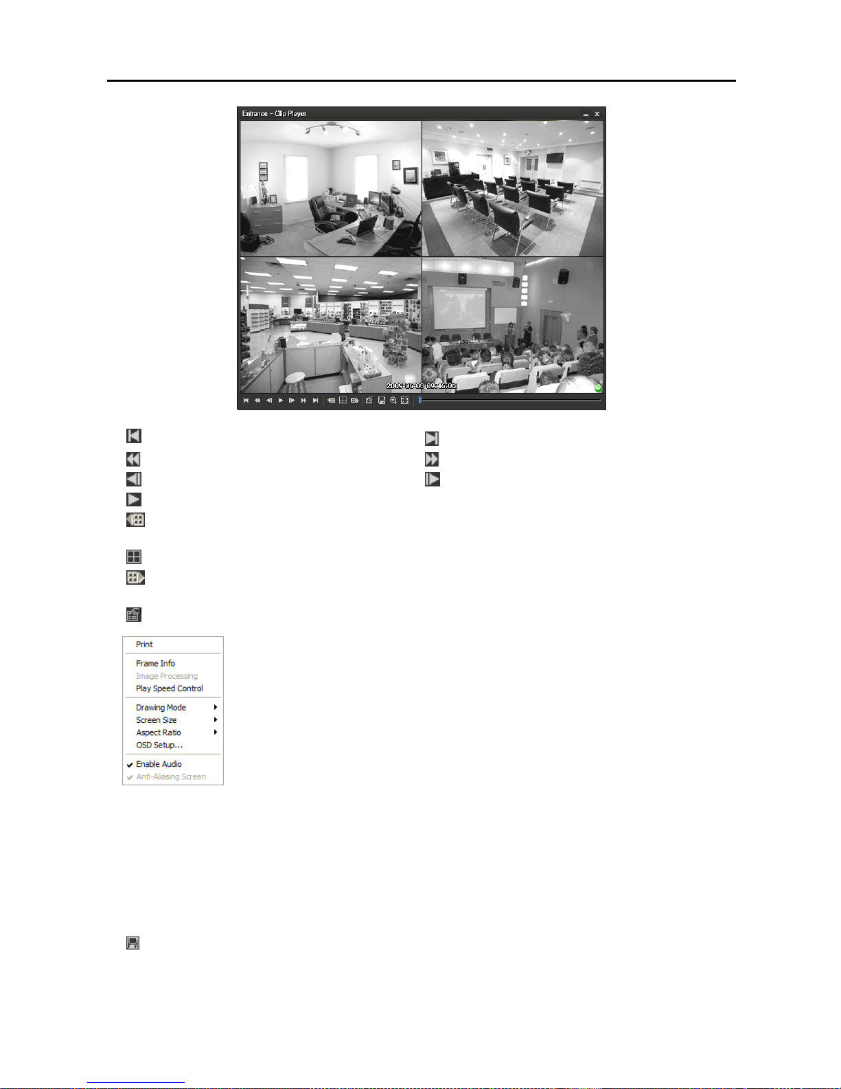
Network Video Recorder
77
: Goes to the beginning of the video.
: Goes to the end of the video.
: Plays the video in fast reverse. : Plays the video in fast forward.
: Goes backward one frame of the video. : Goes forward one frame of the video.
: Plays the video at regular speed.
: Shows the previous camera group if there is recorded video in the previous camera group based on
the current screen format.
: Cycles through the screen formats. It cycles through 2x2, 1+7, 3x3, 4x4, 4x5, 5x5 and 1+32.
: Shows the next camera group if there is recorded video in the next camera group based on the current
screen format.
: Sets up the properties of the player program.
− Print: Prints the current image.
− Frame Info.: Displays Channel, Title, Time, Type, Size and Resolution information
about the image.
− Image Processing: Controls brightness, blur and sharpness of playback images.
(single-screen format only)
− Play Speed Control: Changes the playback speed (Play) or fast forward/backward
playback speed (FF/RW).
− Drawing Mode: Selects the draw mode level. If you are not sure about the best
draw mode level for your system, try each level until the image displays properly.
− Screen Size: Changes the screen size of the player program.
− Aspect Ratio: Changes the image aspect ratio displayed on each camera screen.
− OSD Setup…: Selects options to be displayed on the screen.
− Enable Audio: Plays audio while playing back recorded video that has recorded audio. (single-screen
format only)
− Anti-Aliasing Screen: Enhances image display quality on the screen by smoothing stair-stepping (aliasing)
effects in the enlarged image. If video plays slow because of your CPU’s slow speed, releasing the
Anti-Aliasing Screen option might improve playback speed.
: Saves the current images.
Page 86
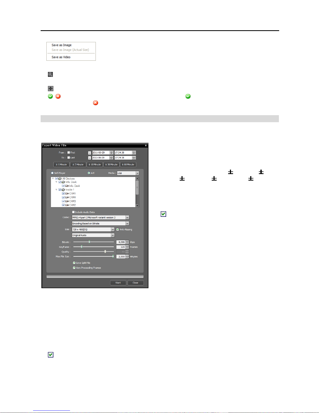
User’s Manual
78
− Save as Image: Saves the current image as a bitmap or JPEG file.
− Save as Image (Actual Size): Saves the current image as a bitmap or JPEG
file in its actual size. (single-screen format only)
− Save as Video: Saves video of desired time range as an AVI file.
: Selects the image size option to enlarge the image or display the image in its actual size (single-screen
format only). You can move the enlarged image by clicking the left mouse button and dragging.
: Displays the image in the full screen.
, : Is displayed at the bottom-right corner of the screen. indicates that the clip file has not been
tampered with, and indicates that the system has detected tampering and playback stops.
Exporting as an AVI File
The recorded video is exported as an AVI file (.avi).
From, To: Enter the date and time of video to export.
Selecting First sets the date and time to the date and
time of the first recorded video. Selecting Last sets
the date and time to the date and time of the last
recorded video. Clicking the
1 Minute,
3
Minute,
10 Minute, 30 Minute or 60 Minute
button increases or decreases the time by the selected
amount from the time selected on the timetable.
Self-Player, AVI: Select AVI.
Media: Select a storage device.
Include Audio Data: Includes audio data when
saving video with recorded audio. This option is not
available when more than one camera is selected.
Audio might not be saved properly when the recording
speed is set to less than 1 ips.
Codec, Bitrate, Quality: Set up the desired values for
compressing the file.
− Encoding Based on Bitrate: Encodes video based
on the bitrate. Selecting this option enables the
Bitrate setting below.
− Encoding Based on Video Quality: Encodes video
based on the quality. Selecting this option enables
the Quality setting below.
Size: Set up the file size for compressing the file.
− Original Ratio: Saves images with fitting within the screen size while maintaining their original ratio.
− Fit to Screen: Saves images with fitting to the screen size regardless of the aspect ratio regardless of
the aspect ratio.
− Fit to Screen (Aspect Ratio): Saves images with fitting to the screen size keeping the aspect ratio.
This might cause top and bottom or left and right side of images to be cropped depending on the screen
size. This aspect ratio is not supported and Original Ratio is applied for camera screens that the following
function is activated: Image Zoom.
Anti-Aliasing: Enhances image display quality for all cameras on the screen by eliminating stair-stepping
(aliasing) effects in the enlarged image.
Keyframe: Sets up the keyframe for compressing the file.
Page 87

Network Video Recorder
79
Max. File Size: Sets up the maximum file size.
Save Split File: Exports video by creating multiple files of the Max. File Size units set above when
the data file reaches the maximum file size. If this option is not selected, it exports only as much as the
maximum file size.
View Proceeding Frames: Displays a popup window showing the video currently being exported.
Playing AVI File
Run the video player program and open the exported AVI file. If the codec selected during exporting video
as an AVI file is not installed, you will need to install the codec manually.
Page 88

User’s Manual
80
Page 89
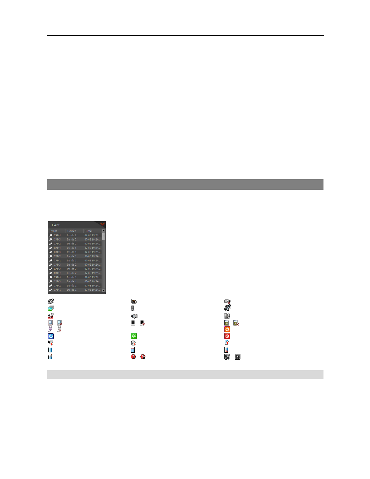
Network Video Recorder
81
Chapter 7 — Event Handling
You can monitor video from a camera where an event is detected and play back event-recorded video. Event
related functions may not be supported depending on the protocol that the device uses and device model
(supported protocols: SiRiS protocol, some versions of the Axis/Panasonic WV (DG)/ONVIF
TM
Conformance
protocols). Ask your dealer or distributor for details.
First, check the following.
Devices should be added to a device group. Refer to Chapter 11 — Device Management (p. 93) for
details.
There should be recorded data in the allocated storage. Refer to Chapter 13 — Storage Management
(p. 113) for details.
The event detection functions of the device should be enabled.
7.1 Handling a Monitoring Event
You can monitor live video from a camera where an event is detected or play back event-recorded video
if video of the selected event has been recorded.
The event list displays live and callback events from the registered devices. The
callback events are listed only when the remote callback function is set up in the
device.
You can change the options of the event list display during Menu – Preference
Settings. Refer to 3.3 Client, Menu – Preference Settings (p. 34) for details.
The description of event icons which are displayed in the event list is as follows
(some event icons may not be supported, depending on the specifications and version
of the device):
Motion Detection
Video Blind Video Loss
Object Detection
Audio Detection
Video Analytics Detection
Trip-Zone
Tampering
Text-In
/
Alarm-In On/Off
/
Alarm-In Bad/Good
/ External Storage In/Out
/
Device Connected/Disconnected
System Boot Up
System Alive
System Restart System Shut Down
Recorder Bad
Disk S.M.A.R.T. Disk Bad
Disk Full
Disk Almost Full Disk Config Change
Disk Temperature / Panic Recording On/Off / Fan Error On/Off
Monitoring Video
Monitoring video from a camera where an event is detected is supported in the Live panel (maximum 4).
If a Live tab is not on the tab panel, go to the System menu, click New Tab and Live.
Page 90
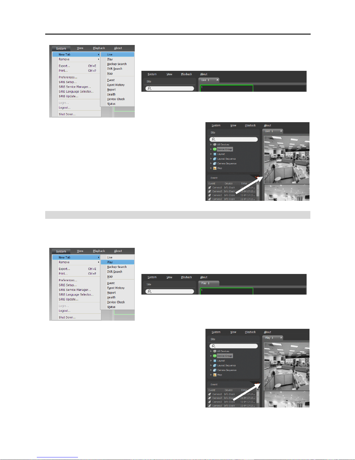
User’s Manual
82
Click the Live tab in the tab panel → Select a desired event from
the event list and drag and drop it on the Live screen. Live video
from the camera where the selected event occurred is displayed
on the screen.
Playing Video
Playing event-recorded video is supported in the Play panel. If the Play tab is not on the tab panel, go to
the System menu, click New Tab and Play.
Click the Play tab on the tab panel → Select a desired event
from the event list and drag and drop it on the Play screen. The
event-recorded video is displayed on the screen.
Page 91
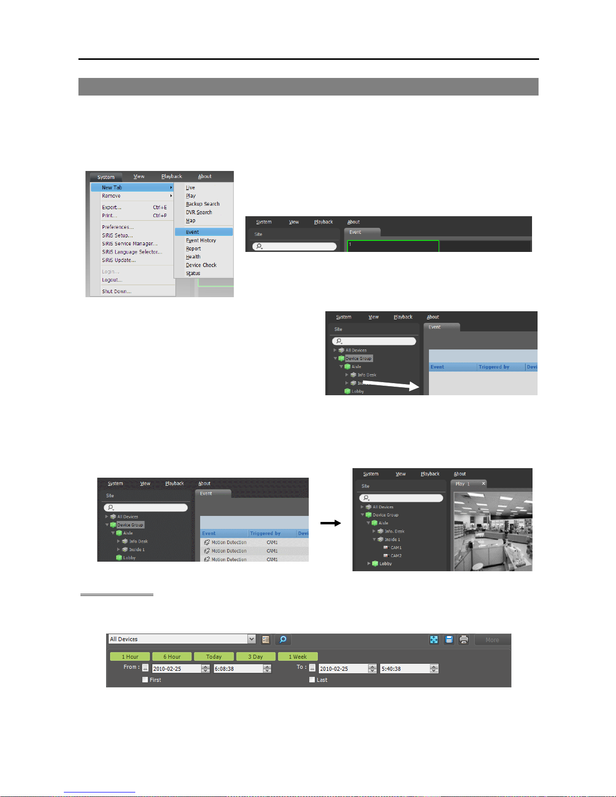
Network Video Recorder
83
7.2 Handling Event Recorded Video
You can play back video which is recorded during Event recording.
Playback of event-recorded video is supported in the Event panel. If the Event tab is not on the tab panel,
go to the System menu, click New Tab and Event.
1. Click the Event tab on the tab panel → Select a device
or camera to connect to from the Site list, and drag
and drop it on the Event panel. The list of events
recorded during Event recording is displayed in the
Event panel. Clicking the right mouse button on a
column header displays a menu and allows you to
sort data as you want.
2. Double click the desired event in the Event panel. the Play panel is displayed and the event video is
displayed on the Play screen. Clicking the right mouse button allows you to select a desired Play panel.
If other cameras were associated with the Event Recording, recorded video from the associated cameras
is displayed together on the screen.
Event Toolbar
The toolbar at the bottom of the panel allows you to search events recorded during Event recording.
From, To: Set up the date and time of the event to search. Enter a specific date and time or select First or
Last. Clicking the 1 Hour, 6 Hour, Today, 3 Day or 1 Week button adjusts the time interval between
From and To. Selecting First or Last searches events from the first recorded or to the last recorded.
Page 92

User’s Manual
84
(Condition): Selects an event type to search.
(Search): Starts searching events based on search conditions.
(Full Screen): Displays the Event panel in full-screen format.
(Export): Exports the resulting event search list as a text file (.txt) or CSV file (.csv).
(Print): Prints the resulting event search list.
More: Displays more results.
Page 93
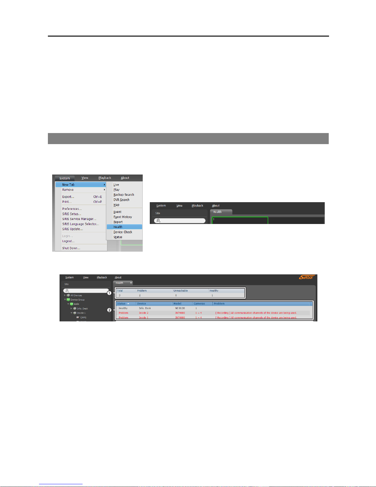
Network Video Recorder
85
Chapter 8 — Device Status Monitoring
You can simultaneously check the status of registered devices.
First, check the following.
Devices should be added to a device group. Refer to Chapter 11 — Device Management (p. 93) for
details.
8.1 Health Monitoring
System health monitoring is supported in the Health panel (supported only for devices registered on recording
services). If the Health tab is not on the tab panel, go to the System menu, click New Tab and Health.
The Client program automatically displays the health monitoring results when the Health tab is added.
① Summary List: Displays the health monitoring status of all devices registered on recording services in
summary.
− Total: Displays the number of devices registered on recording services.
− Problem: Displays the number of devices where a problem is detected.
− Unreachable: Displays the number of devices that are not connected.
− Healthy: Displays the number of devices where no problem is detected.
② Detailed List: Displays the status of each device in detail.
− Status: Displays the status (Healthy: No Problem detected; Problem: Video loss event is detected
or login failed because of the lack of available screens or because the software version is invalid;
Unreachable: The device is not connected).
− Device: Displays the device name.
− Model: Displays the device’s model name.
− Cameras: Displays the number of cameras supported by the device.
− Problem: Displays details regarding the problem.
Page 94
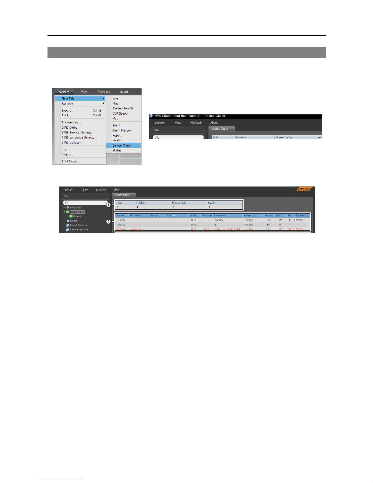
User’s Manual
86
8.2 Device Check
Device check is supported in the Device Check panel (supported only for devices which use the SiRiS protocol).
If the Device Check tab is not on the tab panel, go to the System menu, click New Tab and Device Check.
The Client program automatically displays the device check results when the Device Check tab is added.
① Summary List: Displays the device check status of all devices registered on the administration service
in summary.
− Total: Displays the number of devices registered on the administration service.
− Problem: Displays the number of devices where a problem is detected.
− Unreachable: Displays the number of devices that are not connected.
− Healthy: Displays the number of devices where no problem is detected.
② Detailed List: Displays the status of each device in detail.
− Status: Displays the status (Healthy: No Problem detected; Problem: Video loss event is detected,
alarm in device error or recording error; Unreachable: The device is not connected).
− Problem: Displays details regarding the problem.
− Group: Displays the list of device groups that the device is registered on.
− Site: Displays the device name.
− Address: Displays the IP address of the device.
− Version: Displays the system version information.
− Cameras: Displays the status of cameras that are enabled in the device.
− Alarm In: Displays the status of alarm-in devices that are enabled in the device.
− Recording: Displays the recording status.
− Recording Check: Displays the recording check status.
− Rec. From/To: Displays the recording period.
Page 95
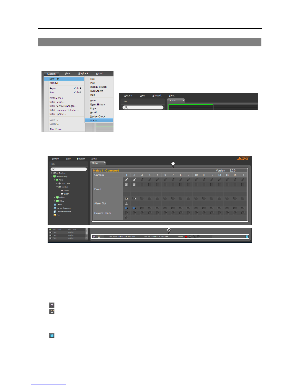
Network Video Recorder
87
8.3 Status Monitoring
Device status monitoring is supported in the Status panel (supported only for devices which use the SiRiS
protocol). If the Status tab is not on the tab panel, go to the System menu, click New Tab and Status.
Select a device to connect to from the Site list, and drag and drop it on the Status panel. The status of the
selected device is displayed.
① Status Display Window: Displays the status as icons.
− Camera: Displays the camera numbers.
− Version: Displays the system version information.
− Event: Displays the status of event detection. When an event is detected, the icon is displayed in
corresponding color. Hovering the mouse cursor over an icon displays the event type in a tooltip.
− Alarm Out: Displays status of the alarm-out signals.
− System Check: Displays the function status of the device and recording.
②
Function Buttons
− (Disconnect): Disconnects the current connection on the Status panel.
− (Panic Recording): Starts or stops panic recording remotely (supported only for DVRs with the panic
recording function).
− Rec. From/To: Displays the recording period.
− Status: Displays the status of recording, playback, archiving, exporting of recorded video.
− (Full Screen): Displays the Status panel in full-screen format.
Page 96

User’s Manual
88
Page 97
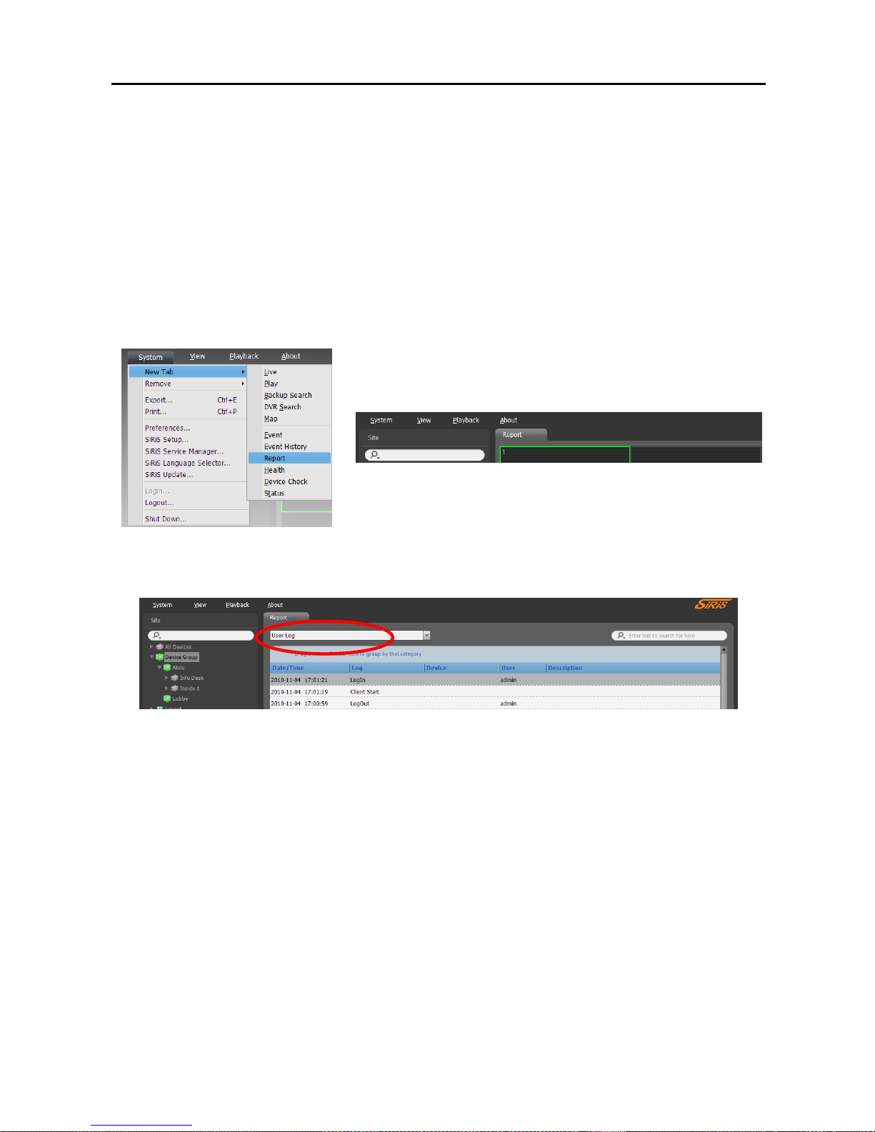
Network Video Recorder
89
Chapter 9 — Log Search
You can search log entries for the SiRiS program and the devices.
First, check the following.
Devices should be added to a device group. Refer to Chapter 11 — Device Management (p. 93) for
details.
Log search is supported in the Report panel. If the Report tab is not on the tab panel, go to the System menu,
click New Tab and Report.
The various types of log entries are displayed. Clicking the right mouse button on a column header displays
a menu and allows you to sort data as you want.
Select a log type to search from the drop-down list.
User Log: Displays log entries from the SiRiS Client program.
Health Log: Displays log entries of the system health monitoring for the registered devices.
Admin Service Log: Displays log entries from the administration service.
Recording Service Log: Displays log entries for each recording service for all registered recording
services.
Streaming Service Log: Displays log entries for each streaming service for all registered streaming
services.
Monitoring Service Log: Displays log entries for monitoring service.
Device System Log: Displays system log entries from the devices.
Device Event Log: Displays event log entries from the devices. If the device is a network camera or
network video transmitter, not all event logs are displayed but only the events that occurred while recording
on an SD (SDHC) memory card is enabled.
Page 98
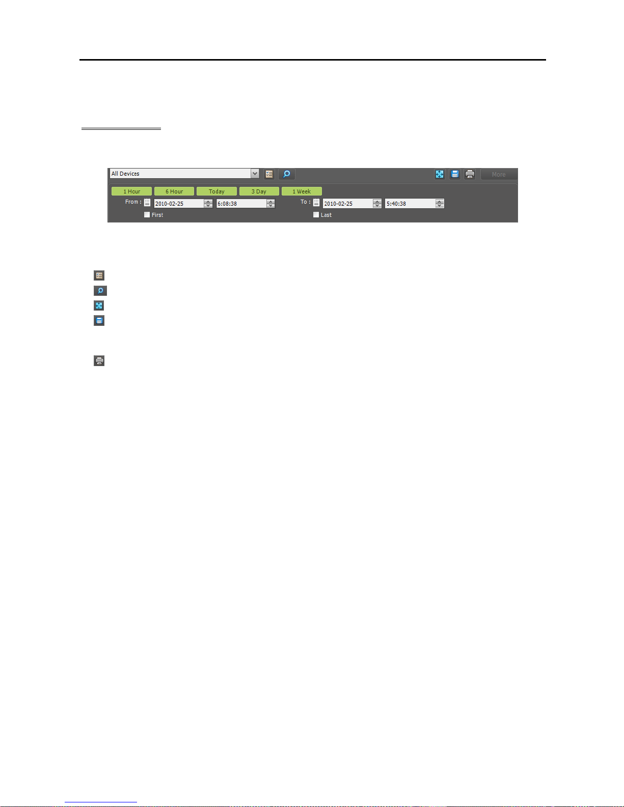
User’s Manual
90
If the connection was not made properly, the network disconnection log is displayed (only for devices
registered on the recording service). Refer to Appendix – Network Disconnection Log (p. 143) for details.
Report Toolbar
The toolbar at the bottom of the panel allows you to search for the desired log entries.
From, To: Set up the date and time of the log entry to search. Enter a specific date and time or select
First or Last. Clicking the 1 Hour, 6 Hour, Today, 3 Day or 1 Week button adjusts the time interval
between From and To. Selecting First or Last searches log entries from the first or to the last.
(Condition): Selects a log type to search.
(Search): Starts searching log entries based on search conditions.
(Full Screen): Displays the Report panel in full-screen format.
(Export): Exports the searched log entries as a text file (.txt) or a CSV file (.csv). System and service
log entries can also be exported as an encrypted HTML file (.html) which will ask you to enter a password
to view the file.
(Print): Prints the searched log entries.
More: Displays more results.
Page 99
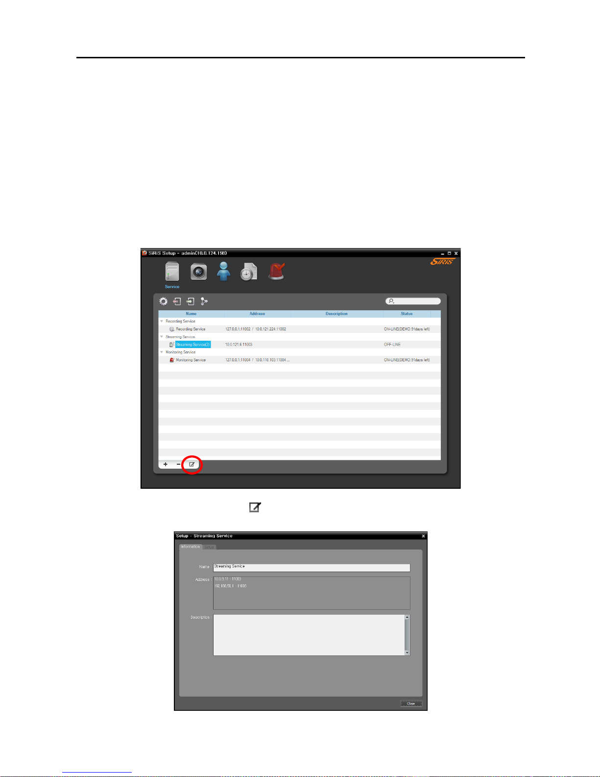
Network Video Recorder
91
Chapter 10 — Streaming
Multiple users can monitor video from devices through the streaming service. When the streaming service
is not running, monitoring is still available, but it is restricted to fewer users based on the maximum number
of simultaneous connections supported by the device.
NOTE: Streaming is not supported for DVRs.
There is no difference in the way to monitor video whether or not the streaming service is running. Refer
to Chapter 4 — Live Video Monitoring (p. 41) for details about monitoring.
Select the Service menu.
1. Select a streaming service and click the
button at the bottom. The Setup – Streaming Service window
appears. Select the Information tab.
Page 100
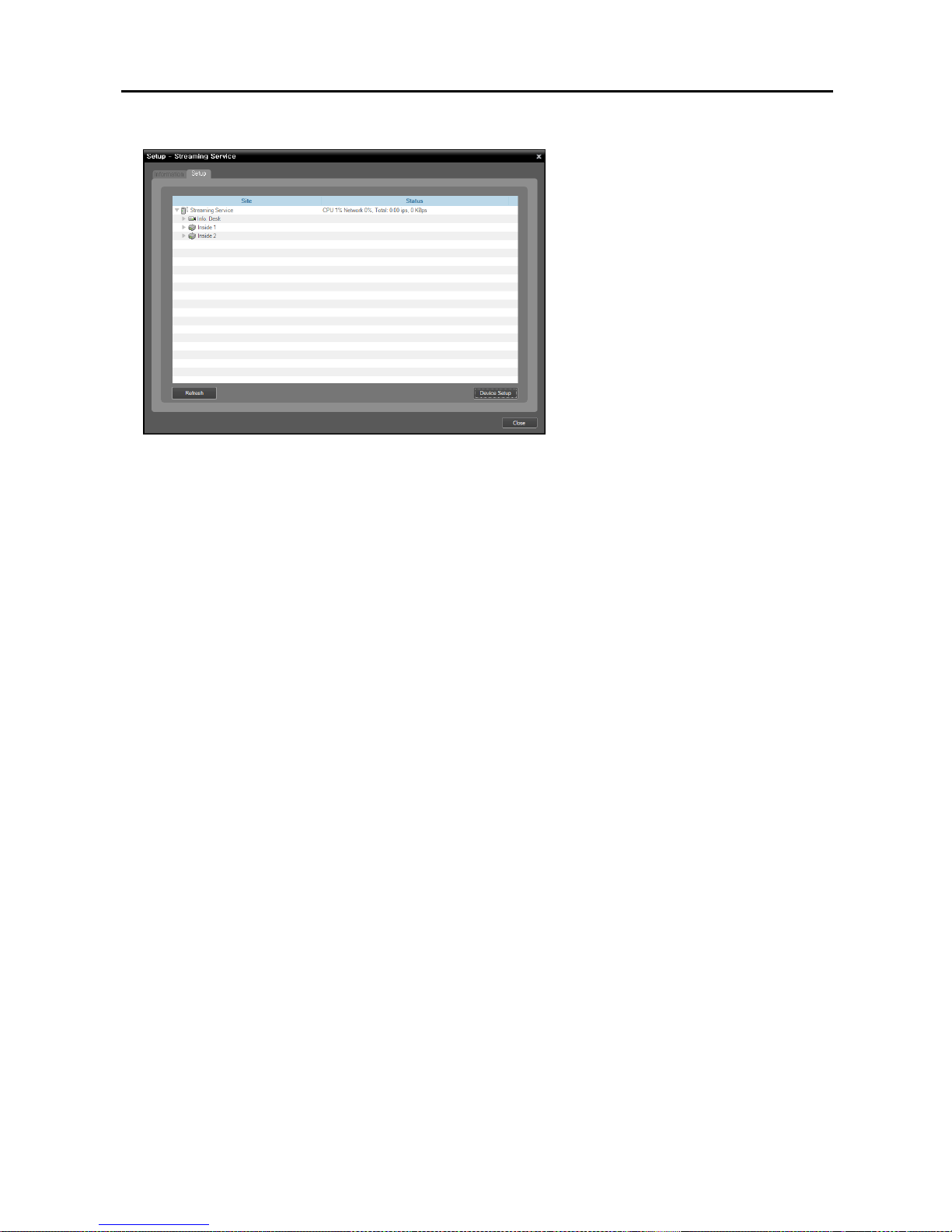
User’s Manual
92
2. Enter the streaming service’s name and select the Setup tab.
The list of cameras registered on the
current streaming service is displayed.
Clicking the Device Setup button at the
bottom allows you to register additional
cameras on the current streaming service
or removes a camera from the current
streaming service.
3. Video from the registered cameras on the current streaming service is streamed to the Client system.
 Loading...