

PACOM PDR-4L User Manual


User’s Manual
ii

Four-Channel Digital Video Recorder
iii
User’s Manual
CAUTION
RISK OF ELECTRIC SHOCK
DO NOT OPEN
CAUTION: TO REDUCE THE RISK OF ELECTRIC SHOCK,
DO NOT REMOVE COVER (OR BACK).
NO USER-SERVICEABLE PARTS INSIDE.
REFER SERVICING TO QUALIFIED
SERVICE PERSONNEL.
The lightning flash with arrowhead symbol, within an equilateral triangle, is intended to alert the user to
the presence of uninsulated "dangerous voltage" within the product's enclosure that may be of sufficient
magnitude to constitute a risk of electric shock.
The exclamation point within an equilateral triangle is intended to alert the user to the presence of
important operating and maintenance (servicing) instructions in the literature accompanying the
appliance
COMPLIANCE NOTICE OF FCC:
THIS EQUIPMENT HAS BEEN TESTED AND FOUND TO COMPLY WITH THE LIMITS FOR A CLASS A DIGITAL DEVICE,
PURSUANT TO PART 15 OF THE FCC RULES. THESE LIMITS ARE DESIGNED TO PROVIDE REASONABLE PROTECTION
AGAINST HARMFUL INTERFERENCE WHEN THE EQUIPMENT IS OPERATED IN A COMMERCIAL ENVIRONMENT. THIS
EQUIPMENT GENERATES, USES, AND CAN RADIATE RADIO FREQUENCY ENERGY AND IF NOT INSTALLED AND USED
IN ACCORDANCE WITH THE INSTRUCTION MANUAL, MAY CAUSE HARMFUL INTERFERENCE TO RADIO
COMMUNICATIONS. OPERATION OF THIS EQUIPMENT IN A RESIDENTIAL AREA IS LIKELY TO CAUSE HARMFUL
INTERFERENCE, IN WHICH CASE USERS WILL BE REQUIRED TO CORRECT THE INTERFERENCE AT THEIR OWN
EXPENSE.
CAUTION: CHANGES OR MODIFICATIONS NOT EXPRESSLY APPROVED BY THE PARTY RESPONSIBLE FOR
COMPLIANCE COULD VOID THE USER? AUTHORITY TO OPERATE THE EQUIPMENT.
THIS CLASS OF DIGITAL APPARATUS MEETS ALL REQUIREMENTS OF THE CANADIAN INTERFERENCE-CAUSING
EQUIPMENT REGULATIONS
THE INTERNAL MODEM OF THIS EQUIPMENT COMPLIES WITH PART 68 OF THE FCC RULES. ON THE BOTTOM OF THIS
EQUIPMENT IS A LABEL THAT CONTAINS, AMONG OTHER INFORMATION, THE FCC REGISTRATION NUMBER, RINGER
EQUIVALENCE NUMBER(REN), AND USOC JACK TYPE FOR THIS EQUIPMENT. YOU MUST, UPON REQUEST, PROVIDE
THIS INFORMATION TO YOUR TELEPHONE COMPANY. THIS EQUIPMENT IS DESIGNED TO BE CONNECTED TO THE
TELEPHONE NETWORK OR PREMISES WIRING USING A COMPATIBLE MODULAR JACK WHICH IS PART 68 COMPLIANT.
THE REN IS USEFUL TO DETERMINE THE QUANTITY OF DEVICES YOU MY CONNECT TO YOUR TELEPHONE LINE AND
STILL HAVE ALL OF THOSE DEVICES RING WHEN YOUR TELEPHONE NUMBER IS CALLED. IN MOST, BUT NOT ALL
AREAS, THE SUM OF THE REN’S OF ALL DEVICE CONNECTED TO ONE LINE SHOULD NOT EXCEED FIVE(5.0). TO BE
CERTAIN OF THE NUMBER OF DEVICES YOU MAY CONNECT TO YOU LINE, AS DETERMINED BY THE REN, YOU
SHOULD CONTACT YOUR LOCAL TELEHONE COMPANY TO DETERMINE THE MAXIMUM REN FOR YOUR CALLING AREA.
IF YOUR TELEPHONE EQUIPMENT CAUSES HARM TO THE TELEPHONE NETWORK, THE TELEPHONE COMPANY MAY
DISCONTINUE YOUR SERVICE TEMPORARILY. IF POSSIBLE, THEY WILL NOTIFY YOU IN ADVANCE, BUT IF ADVANCE
NOTICE IS NOT PRACTICAL, YOU WILL BE NOTIFIED AS SOON AS POSSIBLE. YOU WILL BE INFORMED OF YOUR RIGHT
TO FILE A COMPLIANT WITH THE FCC. YOUR TELEPHONE COMPANY MAY MAKE CHANGES IN ITS FACILITIES,
EQUIPMENT, OPERATIONS OR PROCEDURES THAT COULD AFFECT THE PROPER FUNCTIONING OF YOUR
EQUIPMENT. IF THEY DO, YOU WILL BE NOTIFIED IN ADVANCE TO GIVE YOU AN OPPORTUNITY TO MAINTAIN
UNINTERRUPTED TELEPHONE SERVICE. IF YOU EXPERIENCE TROUBLE WITH THIS TELEPHONE EQUIPMENT, PLEASE
CONTACT YOUR DEALER / INSTALLER FOR INFORMATION ON OBTAIN SERVICE OR REPAIRS. THE TELEPHONE
COMPANY MAY ASK THAT YOU DISCONNECT THIS EQUIPMENT FROM THE NETWORK UNTIL THE PROBLEM HAS BEEN
CORRECTED OR UNTIL YOU ARE SURE THAT THE EQUIPMENT IS NOT MALFUNCTIONING. THIS EQUIPMENT MAY NOT
BE USED ON COIN SERVICE PROVIDED BY THE TELEPHONE COMPANY. CONNECTION TO PARTY LINES IS SUBJECT TO
STATE TARIFFS.
NOTE: THE INTERNAL MODEM IS OPTIONALLY AVAILABLE FOR THE NETWORK-SUPPORTED PREMIUM MODEL.
THE INFORMATION IN THIS MANUAL IS BELIEVED TO BE ACCURATE AS OF THE DATE OF PUBLICATION. IDIS, CO., IS NOT
RESPONSIBLE FOR ANY PROBLEMS RESULTING FROM THE USE THEREOF. THE INFORMATION CONTAINED HEREIN IS SUBJECT TO
CHANGE WITHOUT NOTICE. REVISIONS OR NEW EDITIONS TO THIS PUBLICATION MAY BE ISSUED TO INCORPORATE SUCH CHANGES.
iv
Important Safeguards
Four-Channel Digital Video Recorder
1. Read Instructions
All the safety and operating instructions should be read before the
appliance is operated.
2. Retain Instructions
The safety and operating instructions should be retained for future
reference.
3. Cleaning
Unplug this equipment from the wall outlet before cleaning it. Do not
use liquid aerosol cleaners. Use a damp soft cloth for cleaning.
4. Attachments
Never add any attachments and/or equipment without the approval of
the manufacturer as such additions may result in the risk of fire,
electric shock or other personal injury.
5. Water and/or Moisture
Do not use this equipment near water or in contact with water.
6. Accessories
Do not place this equipment on an unstable cart, stand or table. The
equipment may fall, causing serious injury to a child or adult, and
serious damage to the equipment. Wall or shelf mounting should
follow the manufacturer's instructions, and should use a mounting kit
approved by the manufacturer.
This equipment and cart combination should be moved with care.
Quick stops, excessive force, and uneven surfaces may cause the
equipment and cart combination to overturn.
7. Ventilation
Slots and openings in the cabinet and the back or bottom are provided
for ventilation, and to ensure reliable operation of the equipment and
to protect it from overheating. These openings must not be blocked or
covered. Do not block these openings or allow them to be blocked by
placing the equipment on a bed, sofa, rug, or bookcase. Ensure that
there is adequate ventilation and that the manufacturer's instructions
have been adhered to.
8. Power Sources
This equipment should be operated only from the type of power
source indicated on the marking label. If you are not sure of the type
of power, please consult your equipment dealer or local power
company.
9. Power Cords
Do not allow anything to rest on the power cord. Do not locate this
equipment where the cord will be abused by persons walking on it.
10. Lightning
For added protection for this equipment during a lightning, storm, or
when it is left unattended and unused for long periods of time, unplug
it from the wall outlet and disconnect the antenna or cable system.
This will prevent damage to the equipment due to lightning and
power-line surges.
11. Overloading
Do not overload wall outlets and extension cords as this can result in
the risk of fire or electric shock.
12. Objects and Liquids
Never push objects of any kind through openings of this equipment as
they may touch dangerous voltage points or short-out parts that could
result in a fire or electric shock. Never spill liquid of any kind on the
equipment.
13. Servicing
Do not attempt to service this equipment yourself. Refer all servicing
to qualified service personnel.
14. Damage requiring Service.
Unplug this equipment from the wall outlet and refer servicing to
qualified service personnel under the following conditions:
A. When the power-supply cord or the plug has been damaged.
B. If liquid is spilled, or objects have fallen into the equipment.
C. If the equipment has been exposed to rain or water.
D. If the equipment does not operate normally by following the
operating instructions, adjust only those controls that are covered
by the operating instructions as an improper adjustment of other
controls may result in damage and will often require extensive
work by a qualified technician to restore the equipment to its
normal operation.
E. If the equipment has been dropped, or the cabinet damaged.
F. When the equipment exhibits a distinct change in performance -
this indicates a need for service.
15. Replacement Parts
When replacement parts are required, be sure the service technician
has used replacement parts specified by the manufacturer or that have
the same characteristics as the original part. Unauthorized
substitutions may result in fire, electric shock or other hazards.
16. Safety Check
Upon completion of any service or repairs to this equipment, ask the
service technician to perform safety checks to determine that the
equipment is in proper operating condition.
17. Field Installation
This installation should be made by a qualified service person and
should conform to all local codes.
18. Telnet Communication Cable
Minimum No.26 AWG wire must be used for TNV interconnection
Cable.
19. Danger of explosion if battery is incorrectly replaced.
Replace only with same or equivalent type recommended by
manufacturer. Discard used batteries according to the manufacturer's
instruction.
v

User’s Manual
Table of Contents
Chapter 1. Overview ........................................................................................ 1
1.1 In This Manual ..................................................................................... 1
1.2 Features of the Product........................................................................ 1
Chapter 2. Installation ...................................................................................... 3
2.1 Sample Diagram .................................................................................. 3
2.2 Connecting Components...................................................................... 3
2.3 Front Panel .......................................................................................... 6
2.4 Turning on the Power........................................................................... 8
2.5 Turning off the Power........................................................................... 8
2.6 Factory Reset....................................................................................... 8
Chapter 3. Configuration.................................................................................11
3.1 Overview .............................................................................................11
3.2 System Setup......................................................................................11
3.3 Configuring System Information......................................................... 13
3.4 Configuring for live Monitoring ........................................................... 17
3.5 Configuring for Recording .................................................................. 22
3.6 Configuring for Alarm-In/Out .............................................................. 34
3.7 Configuring for Networking................................................................. 42
3.8 Configuring Other Parameters ........................................................... 49
Chapter 4. Operation ..................................................................................... 57
4.1 Live Monitoring................................................................................... 57
4.2 Recording........................................................................................... 57
4.3 Image Playback ................................................................................. 59
Appendix A. Reviewing Backup Images......................................................... 63
Appendix B. Quick Reference........................................................................ 65
Appendix C. Technical Specifications............................................................. 67
vi

Four-Channel Digital Video Recorder
List of Illustrations
Figure 1 Sample Diagram........................................................................................................3
Figure 2 Rear Panel.................................................................................................................3
Figure 3 Front Panel................................................................................................................ 6
Figure 4 Quick Setup Dialog.................................................................................................. 12
Figure 5 Normal Setup Dialog ...............................................................................................13
Figure 6 Date/Time Setup Dialog .......................................................................................... 14
Figure 7 Holiday Setup Dialog ............................................................................................... 15
Figure 8 System Information Dialog.......................................................................................16
Figure 9 System Information Change Dialog......................................................................... 17
Figure 10 Camera Setup Dialog ............................................................................................ 18
Figure 11 PTZ Setup Dialog .................................................................................................. 19
Figure 12 PTZ Preset Setup Dialog....................................................................................... 20
Figure 13 PTZ Preset View Dialog.........................................................................................20
Figure 14 Live Monitoring ......................................................................................................21
Figure 15 Time-Lapse Record Setup Dialog..........................................................................22
Figure 16 Recording Schedule Setup Dialog......................................................................... 24
Figure 17 Alarm-In Setup Dialog ...........................................................................................25
Figure 18 Motion Detector Setup Dialog................................................................................ 26
Figure 19 Text-In/PTZ Dialog ................................................................................................26
Figure 20 Alarm-In Action ─ Record Setup Dialog .............................................................. 27
Figure 21 Alarm-In Action Schedule Setup Dialog................................................................. 28
Figure 22 Motion Action ─ Record Setup Dialog................................................................. 29
Figure 23 Text-In Action ─ Record Setup Dialog ................................................................30
Figure 24 Video Loss Action ─ Record Setup Dialog.......................................................... 31
Figure 25 Pre-Event Record Setup Dialog............................................................................. 32
Figure 26 Audio Setup Dialog ................................................................................................ 34
Figure 27 Motion Detection Zone Setup Dialog ..................................................................... 36
Figure 28 Text-In Setup Dialog ..............................................................................................37
Figure 29 Alarm-Out Setup Dialog ......................................................................................... 38
Figure 30 Alarm-Out Schedule Setup Dialog ......................................................................... 39
Figure 31 Alarm-In Action ─ Alarm-Out Setup Dialog ......................................................... 40
Figure 32 Motion Action ─ Alarm-Out Setup Dialog ............................................................ 40
Figure 33 Text-In Action ─ Alarm-Out Setup Dialog............................................................ 41
Figure 34 Video Loss Action ─ Alarm-Out Setup Dialog ..................................................... 41
Figure 35 Network Setup Dialog ............................................................................................42
Figure 36 LAN Setup Dialog .................................................................................................. 43
Figure 37 Modem Setup Dialog ............................................................................................. 44
Figure 38 Callback Center (LAN) Setup Dialog .....................................................................45
Figure 39 Callback Center (Modem) Setup Dialog ................................................................46
Figure 40 Alarm-In Action ─ Notify Setup Dialog ................................................................47
Figure 41 Motion Action ─ Notify Setup Dialog ...................................................................47
Figure 42 Text-In Action ─ Notify Setup Dialog................................................................... 48
Figure 43 Video Loss Action ─ Notify Setup Dialog ............................................................ 48
Figure 44 Main Menu Dialog.................................................................................................. 49
Figure 45 Backup Setup Dialog ............................................................................................. 50
Figure 46 Password Setup Dialog ......................................................................................... 51
Figure 47 System Log Dialog ................................................................................................ 53
Figure 48 System Check Setup Dialog ..................................................................................54
Figure 49 RS232 ─ Remote Controller Setup Dialog .......................................................... 56
Figure 50 Calendar Search Dialog......................................................................................... 60
vii

User’s Manual
Figure 51 Date/Time Search Setup Dialog ............................................................................60
Figure 52 Event Log Dialog ................................................................................................... 61
Figure 53 Event Search Dialog (1)......................................................................................... 61
Figure 54 Event Search Dialog (2)......................................................................................... 62
Figure 55 Player Screen ........................................................................................................63
viii

Four-Channel Digital Video Recorder
ix


Four-Channel Digital Video Recorder
Chapter 1. Overview
1.1 In This Manual
This manual describes the procedures for programming and operating the four-channel digital
video recorder (DVR). This manual describes each function using text instructions and
Graphic User Interface (GUI) buttons and dialog boxes. Appendix A contains quick
reference guide for front panel controls and a dialog box map.
1.2 Features of the Product
Your four-channel color DVR provides viewing and recording capabilities for four cameras or
other video sources. It provides exceptional picture quality in both live and playback modes,
and offers the following features:
• NTSC/PAL Compatible (Selector Switch)
• Compact Size
• Dual Recording Modes (Time and Event)
• Remote Monitoring and Playback (Premium Model Only)
• Two Display Formats (Full Screen and 2x2 Screen)
• Live Video Freeze
• On-Screen Display (OSD)
• Programmable Setup of Individual Camera Activity and Intrusion Detection
• User-friendly Graphical User Interface (GUI) Menu System
• 1-Channel Audio Recording and Playback
• ATM/POS Interface Options
• 4-Channel Alarm Input, Alarm Reset Input, 2-Channel Alarm Output, and an Internal
Buzzer
1

User’s Manual
2
Chapter 2. Installation
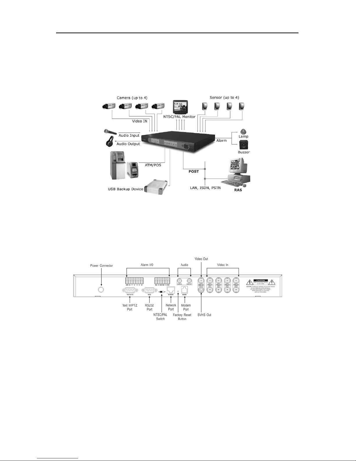
2.1 Sample Diagram
Figure 1 Sample Diagram
2.2 Connecting Components
Rear Panel Connectors
Four-Channel Digital Video Recorder
WARNING: Do not operate the DVR on a carpet or other soft surface that might block
ventilation holes. If you are installing the DVR in a cabinet or rack, make certain there
is adequate ventilation.
Your DVR is designed to work a variety of other equipment. In this section each type of
equipment will be discussed. The basic DVR will consist of a video camera and system
monitor.
Figure 2 Rear Panel
3

User’s Manual
Video In (1-4)
Four video inputs and four video loop outputs are provided for video source connections using
standard BNC connectors. The video inputs accept monochrome or color composite video
signals. The looping video outputs (Loop 1-4), provided for each camera are used to loop
the video signal to other equipment.
NOTE: The BNCs on the DVR are self-terminating. Do not connect a cable to the
Loop connector unless it is connected to a video device because this will defeat the
termination.
Video Out
A composite video output is provided on the Video Out BNC for connection to a B/W or color
video monitor. The SVHS output (mini-DIN connector) is provided for SVHS monitor
connection. Both Video Outs can be used at the same time.
Audio In
One audio input is provided on the Audio In RCA connector. The input only accepts the
line-level signal, so an external pre-amplifier is required to connect a microphone.
Audio Out
One mono audio output(line-level) is provided on the Audio Out RCA connector. This
output allows monitoring of live audio signals or audio signal during playback. An external
audio amplifier is required.
Network Port
The Network Port is a RJ-45 port that supports 10/100 Mbps Ethernet connections.
Modem Port
The Modem Port is a RJ-11 port that supports a telephone line connection.
Text In/PTZ Port
The Text In/PTZ Port is used for either text input or PTZ control. When using for the Text In
port, it supports standard RS-232C ASCII text input on a DB-9P connector. This text source
may be from POS devices, cash registers, ATMs, access control systems, or other sources that
output asynchronous ASCII information. When controlling the PTZ camera via RS485 input,
the additional RS232 to RS485 converter is required.
4

Four-Channel Digital Video Recorder
RS232 Port
A second 9-Pin male plug is provided for RS232C serial communication for either an external
modem connection or a remote controller connection.
Power In
The power connector is provided for connecting DC 24 volt power supply. Connect the DC
power cord of the adaptor to the DVR, and connect the AC power cord to the adaptor and then
to the wall outlet. AC input specifications of the provided adaptor are 100~250 VAC, 50~60
Hz and 1.0 A. The output specifications of the adaptor are 24 VDC and 2.9 A.
Terminal Strip Connections
Alarm In
Four alarm inputs (1-4, 2-ground) are provided for manual alarm activation. The inputs
accept switch closures (door contact, panic buttons) or TTL (transistor-to-transistor) opencollector input signals.
Alarm Out
Two external alarm outputs (both either NC or NO contacts) and one internal buzzer (ARI, G)
for alarm indication are provided. The alarm status is monitored using the alarm output
connected to a visual or audible indicator (flashing light, bell) and the internal buzzer.
Pressing
alarm output during alarm activation. Permitted current is up to 0.6 A for 125 VAC or 110
VDC, 2 A for 30 VDC.
NOTE: The NTSC/PAL switch is located between RS232 plug and Network Port, and
Factory Reset push button is between Network Port and Modem Port.
ALARM resets the alarm (both alarm outputs, and internal buzzer) status by releasing
5
User’s Manual
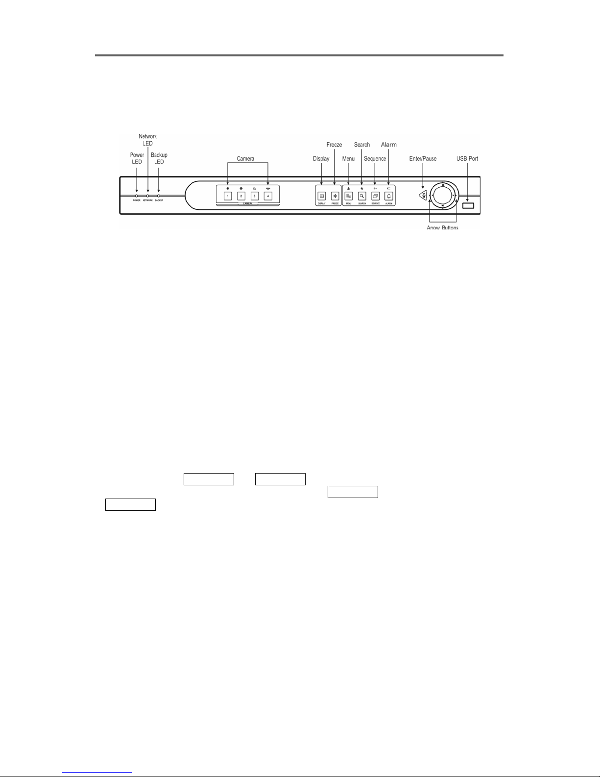
2.3 Front Panel
Front Panel Controls
Figure 3 Front Panel
POWER LED
The POWER LED is lit when the DVR is On.
NETWORK LED
The NETWORK LED is lit when the unit is networked either via Ethernet or modem.
BACKUP LED
The BACKUP LED is lit when data is being backed up using the USB port.
CAMERA Number Button (1-4)
• Selects the camera (1-4) image in the live monitoring mode and the playback mode.
• Enters number when entering the password.
• In the PTZ mode,
opening and closing the IRIS of the PTZ camera. CAMERA 3 sets up the PTZ preset, and
CAMERA 4 loads the PTZ preset.
DISPLAY Button
• Switches between full screen mode and 2x2 screen mode.
FREEZE Button
• Freezes video during live monitoring mode, and releases video freeze by pressing the button
again.
CAMERA 1 and CAMERA 2 control the brightness of the image by
6

Four-Channel Digital Video Recorder
MENU Button
• Displays the dialog box for entering password when the password has been preset. Begins
the menu mode when the entered password matches, and begins the menu mode direct when
the password has not been preset.
• Displays the search menu in the playback mode.
• Closes the current menu or setup dialog box.
• Zooms in on the image of the PTZ camera in the PTZ mode.
SEARCH Button
• Displays the dialog box for entering password when the password has been preset. Begins
the playback mode when the entered password matches, and begins the playback mode
direct when the password has not been preset.
• Goes to the playback mode in the live monitoring mode.
• Zooms out on the image of the PTZ camera in the PTZ mode.
SEQUENCE Button
• Starts/Ends sequential camera switching.
• Makes the focus of the PTZ camera near in the PTZ mode.
ALARM Button
• Resets an alarm during alarm activation.
• Displays the event log in the live monitoring mode, except during alarm activation.
• Makes the focus of the PTZ camera far in the PTZ mode.
Enter/Pause Button
• Selects the item or finishes GUI control input in the menu setup.
• Stops playback in the playback mode.
Up-Arrow Button
• Selects the next image in the playback mode.
• Navigates through menus and GUI during system setup.
• Tilts the PTZ camera up in the PTZ mode.
Down-Arrow Button
• Selects the previous image in the playback mode.
• Navigates through menus and GUI during system setup.
• Tilts the PTZ camera down in the PTZ mode.
7

User’s Manual
Left-Arrow Button
• Plays the images backward. Subsequent selection toggles the 1x/2x/8x backward play
speed.
• Navigates through menus and GUI during system setup.
• Pans the PTZ camera to the left in the PTZ mode.
Right-Arrow Button
• Plays the images forward. Subsequent selection toggles the 1x/2x/8x forward play speed.
• Navigates through menus and GUI during system setup.
• Pans the PTZ camera to the right in the PTZ mode.
USB Port
• A USB port is provided to connect external hard disk drives for archiving video. Position
the external hard disk drive close enough to the DVR so that you can make the cable
connections usually less than 6 feet. Use the USB cable provided with the hard disk drive
to connect it to the DVR.
2.4 Turning on the Power
The DVR is operational in approximately 30 seconds after the power cable is connected to the
DVR. The Power LED on the front panel will turn ON, and this action signifies the DVR
has been turned on properly.
2.5 Turning off the Power
The DVR may be powered down by unplugging the power cord at the rear of the DVR. No
on/off switch is provided.
2.6 Factory Reset
CAUTION: When factory reset is launched, all previously recorded data will be deleted
and all programming configurations will be reset as the factory default setting.
1. Remove power from the DVR and reapply. When the power is reapplied, all front panel
LEDs will illuminate.
8

Four-Channel Digital Video Recorder
2. After approximately 20 seconds the front panel LEDs will extinguish. At this time, press
the recessed Factory Reset push button located on the back panel with a sharp pin and
maintain the button depression for 10 seconds. If the factory reset is performed
successfully, all of the button LEDs will blink three times. Otherwise repeat from step 1.
9

User’s Manual
10

Four-Channel Digital Video Recorder
Chapter 3. Configuration
3.1 Overview
Your DVR provides a Graphic User Interface (GUI) for easy system programming and
operation. The front panel push-button controls are used to enter system commands and for
programming. A system video monitor must be connected to the video-out connector (BNC
or SVHS) to view the video and programming screens.
3.2 System Setup
Press
MENU
password. Refer to 3.8 Configuring Other Parameters ─ Enable/Disable Password
section for details of setting up the password. Disabling the Quick Setup and closing the
Quick Setup screen goes to the Normal Setup screen displaying the GUI with eight
programming icons (buttons) at the bottom. In the system setup mode, press
from the setup mode, and go to the live monitoring mode.
3.2.1 Quick Setup
As well as the Normal Setup, the DVR also supports the Quick Setup for system programming.
The factory default is the Quick Setup. In the Quick Setup mode, the user can program the
following options for each camera input:
• Quick Setup On/Off
• Recording Speed/Image Quality
• Audio Recording
• Sequence Dwell Time
• System Information
• Camera Selection & Titling
• Network Configuration (Network-supported Premium Model Only)
• Security (Password)
• Date/Time Initialization
on the front panel to initialize the Quick Setup screen after confirming the setup
MENU
to exit
11
User’s Manual
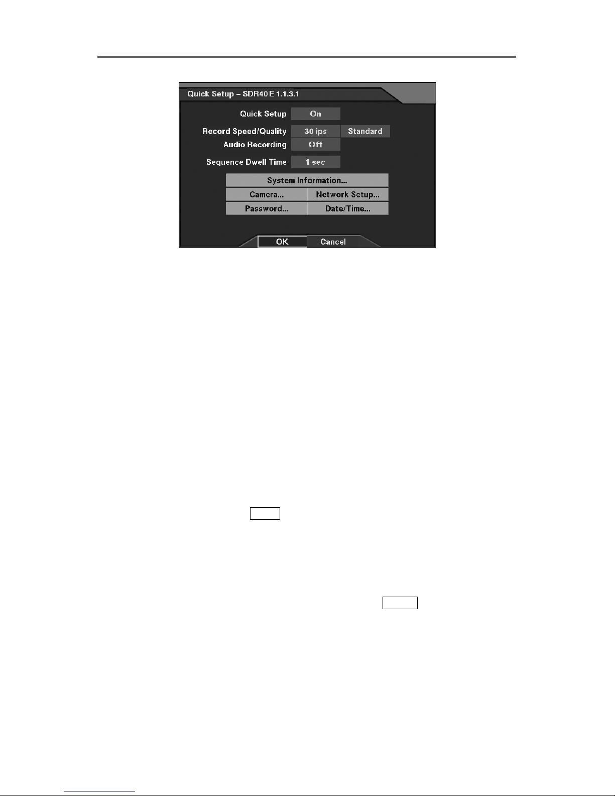
Figure 4 Quick Setup Dialog
Quick Setup
• Quick Setup: Enable or disable Quick Setup.
• Record Speed: Set the recording speed (1/30ips~30ips).
• Record Quality: Set the recording image quality (Very High, High, Standard and Low).
• Audio Recording: Enable or disable audio recording (On/Off).
• Sequence Dwell Time: Set the camera sequencing dwell time (1 sec~6 sec).
• System Information: Set up the system information (Refer to Figure 8 System Information
Dialog.).
• Camera: Set up camera information (Refer to Figure 10 Camera Setup Dialog.).
• Network Setup: Set up network information (Refer to Figure 35 Network Setup Dialog.
Network-supported premium model only).
• Password: Set up the password (Refer to Figure 46 Password Setup Dialog.).
• Date/Time: Set up the date/time (Refer to Figure 6 Date/Time Setup Dialog.)
3.2.2 Normal Setup
To select the Normal Setup, press
screen first. Select Off in the Quick Setup field, and exit from the menu by pressing OK.
The DVR will reload default settings if Yes is selected. The Normal Setup screen is then
displayed. To go back to the Quick Setup, select Quick Setup in the Configuration menu.
In the Normal Setup mode, the user can program each of eight menu options in detail. Refer
to the Appendix A. Quick Reference ─ Reference Dialog Map for the setup menu
configuration. The menu icons (buttons) at the bottom of the Normal Setup screen can be
scrolled through by arrow buttons on the front panel. Pressing
setup menu displays the setup dialog box. Section 3.3~3.8 describes the detailed instructions
to configure programming functions. The programming operation is described in each
section using the PATH description, screen dialog and explanation text.
MENU
on the front panel to display the Quick Setup
ENTER
after selecting the
12
Four-Channel Digital Video Recorder
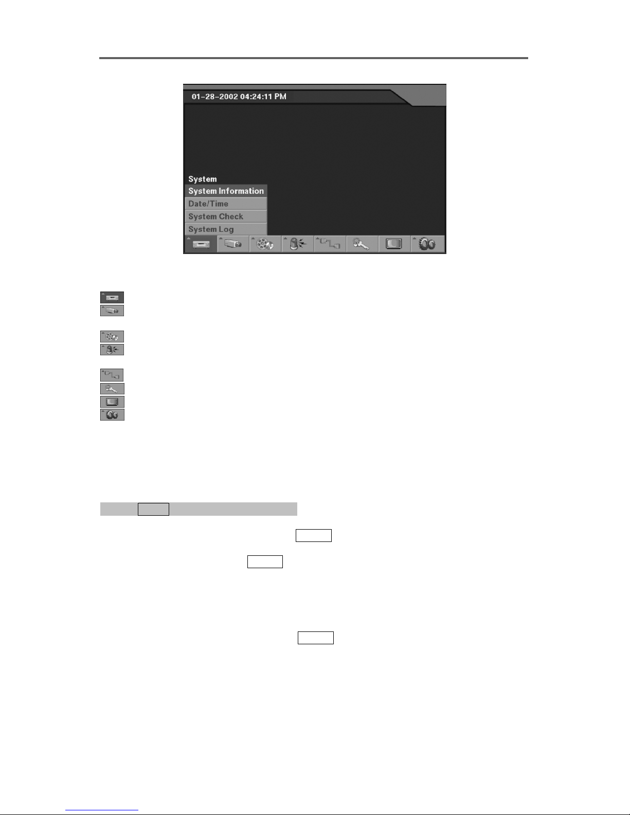
Figure 5 Normal Setup Dialog
System: System Information, Date/Time, System Check, and System Log Setup
Devices: Camera, Alarm-In, Motion Detector, Text-In/PTZ, Alarm-Out, Audio, and
RS232 Setup
Record: Time-Lapse Record and Pre-Event Record Setup
Event Action: Alarm-In Action, Motion Action, Text-In Action, and Video Loss Action
Setup
Network: Network and Callback Center Setup
Password: Password Setup
Live Monitoring: Sequence Dwell Time Setup, and OSD Setup
Configuration: Quick Setup, Load Default Setup, and Clear All Data Setup
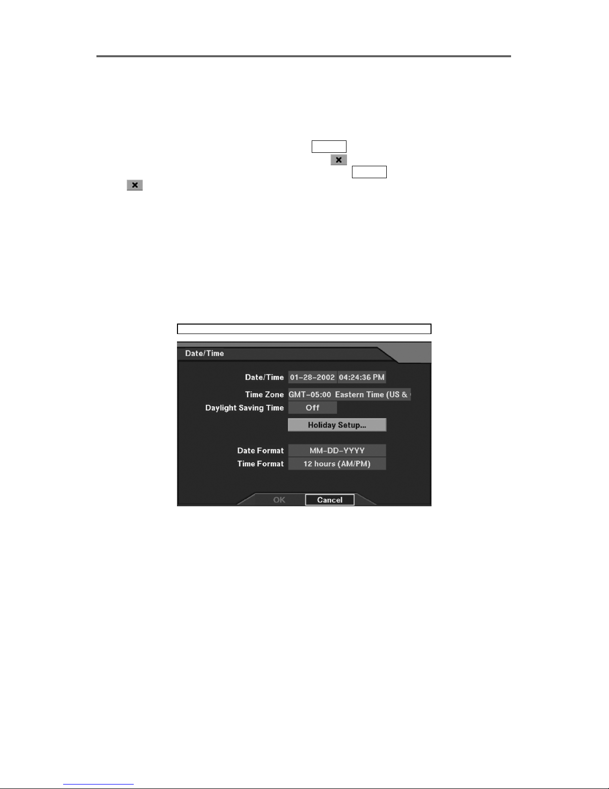
3.3 Configuring System Information
Set up System Date/Time
0PATH: MENU ▶ System ▶ Date/Time0
1. Move to the Date/Time field, and press
arrow buttons and change the field using left/right-arrow buttons on the front panel.
Finish the setting by pressing
ENTER.
NOTE: If you change the system time, the DVR will restart.
NOTE: The newly set time starts upon selecting OK and entering the Admin password.
2. Move to the Time Zone field, and press
shown.
3. Move to the Daylight Savings Time field, and select either On or Off.
ENTER. Change the values using the up/down-
ENTER to select the proper time zone from the list
13
User’s Manual
NOTE: The system time and daylight saving time settings cannot be changed at the
same time. Set the use of daylight saving time first, and then change the system time.
The DVR will restart twice in order to change both the system time and the daylight
saving time settings.
4. Move to the Holiday Setup button, and press
box. Set up the holiday schedule using Add and
the Add button, and set the date then add it by pressing
the
button next to the target date.
ENTER to display the Holiday Setup dialog
buttons. To add holidays, press
ENTER. To delete holidays, press
NOTE: Update the holiday(s) every year when the holiday information has been
changed for the current year.
5. Move to the Date Format field to select the date format (MM-DD-YYYY, DD-MM-YYYY,
YYYY-MM-DD, MM/DD/YYYY, DD/MM/YYYY, or YYYY/MM/DD).
6. Move to the Time Format field to select the time format (24 Hours/12 Hours (AM/PM)).
CAUTION: If you change the time to the past, recorded images dated later than the
new date/time are deleted immediately.
System ► Date/Time
14
Figure 6 Date/Time Setup Dialog
 Loading...